5高频功放
高频电子线路(第五章 高频功率放大器)

高频功率放大器和低频功率放大器的共同 特点都是输出功率大和效率高。
7
(3)高频功率放大器的种类
谐振功率放大器(学习重点)
特点是负载是一个谐振回路,功率放大增益可
以很大,一般用于末级; 不易于自动调谐。
宽带功率放大器(了解即可)
特点是负载是传输线变压器,可在很宽的频带
工作状态 甲类 乙类 甲乙类 丙类 丁类 半导通角 c=180° c=90° 90° <c<180° c<90° 开关状态 理想效率 50% 78.5% 50%<h<78.5% h>78.5% 负 载 电阻 推挽,回路 推挽 选频回路 选频回路 应 用 低频 低频,高频 低频 高频 高频
90%~100%
由于这种周期性的能量补充,所以振荡回路能维持振 荡。当补充的能量与消耗的能量相等时,电路中就建立起 动态平衡,因而维持了等幅的正弦波振荡。
34
问题二:半流通角θc通常多大合适?
如果θc取值过大,趋向甲类放大器,则效率 太低; 如果θc取值过小,效率虽然提高了,但输出 功率的绝对值太小(因为iC脉冲太低); 这是一对矛盾,根据实验折中,人们通常 取
gC (vB VBZ )(当vB VBZ )
外部电路关系:
vB VBB Vbm cos t
v C V CC V cm cos t
31
(4)对2个问题的解释
问题一(可能会引起同学们困惑的问题)
为什么iC的波形时有时无,而输出的波形vo却能
是连续的?
问题二(有的题目已知条件不给θc,而解题 中又需要θc )
通过LC回路,滤去无用分量,只留下 Icm1cosωt分量
高频功率放大器的工作原理
高频功率放大器的工作原理高频功率放大器是一种电子器件,主要用于放大高频信号,并将其输出到负载上。
其工作原理基于电子管或晶体管的放大作用,在输入的高频信号上增加电压,从而实现信号放大的目的。
高频功率放大器广泛应用于无线电通信、雷达、卫星通信等领域。
最常用的高频功率放大器是基于晶体管的,其内部结构由多个不同功能的电路组成。
其中,收发信道通过变压器进行隔离,从而实现信号的单向传输。
在信号放大方面,晶体管的三个引脚分别为基极、集电极和发射极。
输入信号通过基极进入晶体管,集电极则是放大后的信号输出。
发射极则是提供功率的地方,通常在晶体管的大功率管中被找到。
高频功率放大器通常需要很高的驱动电压,它可以由直流电源提供。
晶体管的放大过程是通过电荷扩散和电场漂移来完成的。
在多数晶体管中,材料内部的电子浓度是不均匀的,因此电子在晶体中移动时会发生扩散。
此外,由于电场的存在,电子也会沿着电场方向移动,从而形成漂移的过程。
这两种运动将使得电子的浓度差异减小,最终导致电流被放大。
需要注意的是,在高频电路中,信号通常在不同的电阻、电容和电感之间进行传输,因此高频功率放大器要求不仅具有高放大倍数、低噪声等特点,还需要适应各种不同的阻抗,防止信号反射和损耗。
为了保证高频信号的传输质量,高频功率放大器通常采用多级级联的方式,以达到更高的放大倍数和更佳的工作效率。
总之,高频功率放大器是电子工程领域中极为重要的技术,其工作原理基于电子器件的放大作用。
通过不同级联和高数据速率的设计,高频功率放大器可以实现高精度的信号传输和处理,对无线电通讯、雷达、卫星通讯等领域具有举足轻重的作用。
高频功率放大器的基本原理(一)

高频功率放大器的基本原理(一)高频功率放大器的基本原理1. 什么是高频功率放大器高频功率放大器是一种用于增强高频信号幅度的电子设备。
它通常用于无线通信、雷达、高频电视和天线系统等领域。
高频功率放大器可以将低功率的高频信号放大到足够大的功率,以便传输和处理。
2. 高频功率放大器的工作原理高频功率放大器的工作原理可以简单分为三个步骤:放大输入信号、增加信号的功率和输出放大后的信号。
2.1 放大输入信号高频功率放大器的第一个任务是放大输入信号。
它通常使用晶体三极管(BJT)或场效应晶体管(FET)作为放大器的关键元件。
这些元件根据输入信号的幅度和频率变化进行放大操作。
2.2 增加信号的功率放大后的信号仍然可能是低功率的,因此高频功率放大器的下一个任务是增加信号的功率。
这一步骤通常通过使用功率放大器级联来实现。
级联多个放大器可以将信号功率从较低级别逐步增加到所需的功率级别。
2.3 输出信号在增加信号的功率之后,高频功率放大器将输出放大后的信号。
这个信号可以被用于进一步的处理或传输。
输出信号的幅度将取决于放大器的设计和配置。
3. 高频功率放大器的关键考虑因素在设计高频功率放大器时,需要考虑一些关键因素来确保性能和稳定性。
3.1 频率响应高频功率放大器应该能够在指定的频率范围内提供稳定的放大。
对于不同的应用,频率范围和响应要求会有所不同。
3.2 功率输出高频功率放大器应该能够提供足够的功率输出,以满足特定应用的需求。
功率输出的大小通常由设备和系统的要求来确定。
3.3 效率高频功率放大器的效率是指输入功率与输出功率之间的比率。
高效率的放大器能够最大限度地利用输入能量,减少能量浪费。
3.4 线性度高频功率放大器的线性度是指输出信号与输入信号之间的线性关系。
较好的线性度可以保持输入信号的准确度和完整性。
3.5 稳定性高频功率放大器的稳定性是指在各种工作条件下保持良好的性能。
它应该能够在不出现振荡或失真的情况下工作。
高频功率放大器简介

高频功率放大器简介
高频功率放大器,又称射频功率放大器,是一种能量转换器件,它将电源供给的直流能量转换成为高频交流输出。
高频功率放大器用于发射机的末级,作用是将高频已调波信号进行功率放大,以满足发送功率的要求,然后经过天线将其辐射到空间,保证在一定区域内的接收机可以接收到满意的信号电平,并且不干扰相邻信道的通信。
高频功率放大器是通信系统中发送装置的重要组件。
按其工作频带的宽窄划分为窄带高频功率放大器和宽带高频功率放大器两种,窄带高频功率放大器通常以具有选频滤波作用的选频电路作为输出回路,故又称为调谐功率放大器或谐振功率放大器;宽带高频功率放大器的输出电路则是传输线变压器或其他宽带匹配电路,因此又称为非调谐功率放大器。
高频功率放大器大多工作于丙类。
但丙类放大器的电流波形失真太大,因而只能用于采用调谐回路作为负载的谐振功率放大。
由于调谐回路具有滤波能力,回路电流与电压仍然极近于正弦波形,失真很小。
一、高频放大器的特点
1. 采用谐振网络作负载。
2. 一般工作在丙类或乙类状态。
3. 工作频率和相对通频带相差很大。
4. 技术指标要求输出功率大、效率高。
二、高频功率放大器的技术指标
主要技术指标有:输出功率、效率、功率增益、带宽和谐波抑制度(或信号失真度)等。
这几项指标要求是互相矛盾的,在设计放大器时应根据具体要求,突出一些指标,兼顾其他一些指标。
5w功放芯片

5w功放芯片5W功放芯片是一种功率放大器,用于电子设备中,为音频和视频提供强有力的放大功能。
这种芯片能够将低电压的信号进行放大,以达到更大的音量和更清晰的画面效果。
它在各种电子产品中得到广泛应用,如手机、电视、音响等。
下面将详细介绍5W功放芯片的特点和应用领域。
首先,5W功放芯片具有小体积、低功耗的特点。
由于采用了先进的半导体技术和优化的电路设计,5W功放芯片可以实现更高的功率放大,在体积上比传统的功放芯片要更小,同时功耗相对较低。
这使得5W功放芯片适用于那些空间有限和对电池续航能力要求较高的设备,如智能手机、便携式音箱等。
其次,5W功放芯片具有高性能的特点。
采用了多种先进的电路设计和信号处理技术,5W功放芯片能够提供更高的音频和视频质量。
它能够将信号放大到足够的功率,以使音乐更有动态感和层次感,视频更清晰锐利。
同时,5W功放芯片还具有良好的抗干扰能力,能够有效降低噪音和杂音的干扰,提升音质和图像的还原度。
此外,5W功放芯片还具有灵活的应用。
它可以根据不同的需求进行定制和配置,适应不同的音频和视频输出要求。
例如,在手机中,5W功放芯片可以用于驱动内置扬声器,提供更好的声音效果;在音响中,它可以用于驱动大功率的喇叭,提供更高的音量;在电视中,它可以用于驱动显示屏,提供更清晰的画面。
5W功放芯片的灵活性使得它可以广泛应用于各种电子设备中,提供更好的用户体验。
最后,5W功放芯片具有高可靠性和稳定性。
它经过严格的品质控制和稳定性测试,能够在不同的工作环境和温度条件下正常运行。
此外,5W功放芯片还具备过压、过流和短路保护功能,可以有效保护设备和芯片自身的安全。
这使得5W功放芯片可以长时间稳定地工作,无需频繁维修和更换。
总而言之,5W功放芯片是一种具有小体积、低功耗、高性能、灵活应用、高可靠性和稳定性的功率放大器。
它广泛应用于各种电子设备中,为音频和视频的放大提供强有力的支持。
随着科技的不断进步和应用需求的不断增加,5W功放芯片将进一步改进和提升,为用户带来更好的音视频体验。
高频功率放大器
3.1 谐振功率放大器
(2)晶体管输出电流、电压波形
当基极输入一余弦高频信号ui=ubm cos( ωt)时,基极与发 射极之间的电压为
(3. 1)
上一页 下一页 返回
3.1 谐振功率放大器
其波形如图3一3(a)所示,当ube的瞬时值大于晶体管的导通电 压UBZ时,晶体管导通,产生基极脉冲电流,由转移特性可 得集电极流过的电流或也为脉冲波形,如图3一3 (b)所示。将
下一页 返回
3.1 谐振功率放大器
2.工作原理 谐振高频功率放大器的发射结在UBB的作用下处于负偏压
状态,当无输入信号电压时,晶体管处于截止状态,集电极 电流ic = 0。当输入信号为ui=ubm cos( ωt)时,基极与发射极 之间的电压为ube =UBB +ubm cos(ω t )。为分析电路的工作波 形,先对晶体管的特性曲线进行折线化处理,处理后分析与 计算大大简化,但误差也大,所以实际电路工作时需要调整。
流电阻很小,也可近似认为短路。这样,脉冲形状的集电极
电流ic经谐振回路时,只有基波电流才产生电压降,因而LC 谐振回路两端输出不失真的高频信号电压uc。
(3. 3)
上一页 下一页 返回
3.1 谐振功率放大器
式中Ucm=ReIc1m,为基波电压幅度,所以晶体管的输出电 压为
其波形如图3一3(c)所示。
上一页 下一页 返回
3.1 谐振功率放大器
(1)特性曲线的折线化 对高频谐振功率放大器进行精确计算是十分困难的,为了
研究谐振功率放大器的输出功率、管耗、效率,并指出一个 大概的变化规律,可采用近似估算的方法,即对特性曲线进 行折线化处理:忽略高频效应,晶体管按照低频特性分析;忽 略基区宽变效应,输出特性水平、平行且等间隔,如图3-2 (a) 所示;忽略管子结电容和载流子基区渡跃时间;忽略穿透电流, 截止区ICEO = 0。
高频功率放大器

第2章高频功率放大器第2章高频功率放大器2.1 谐振功率放大器基本工作原理2.2 丙类谐振功率放大器的工作状态分析2.3 谐振功率放大器的高频特性2.4 谐振功率放大器电路2.5 高效率高频功率放大器及功率合成技术第2章高频功率放大器一、工作状态分类A 类(甲类)、B 类(乙类)、C 类(丙类)等。
i i BEC tCu QA 类(甲类):工作点Q 较高(I CQ 大),信号360°内,管子均导通。
通角:θ=180 °U CCR LR L′N 1∶N 2RBVCBu i第2章高频功率放大器甲类功放电路及交、直流负载线i Ct 0I C Q I C QI C Qu CE i Cu CEt00U CE QU CU CCQ直流负载线交流负载线i B1R L′-I CR B 为偏置电阻,决定Q 点的I CQ 及I BQ 。
变压器是理想的,则直流工作点电压U CEQ =U CC ,直流负载线为一垂直线,而交流负载线通过Q 点,其斜率为(-1/R ′L )第2章高频功率放大器CQCC C CQ CC TE I U dt t I I U TP ⋅=+=∫)sin (10ω1.电源功率P E2. 交流输出功率P LLC C C C C TL R U I U tdt I t U TP ′=⋅=⋅=∫22121sin sin 1ωωCC Cm U U =CQCm I I =CQCC CC E L I U I U P P 21==ηA 类放大器无信号时,效率为零,信号最强时最大效率只有50%。
这是A 类放大器的致命弱点,也是晶体管功率放大器极少采用A 类放大器的原因。
%50max =η一般: 20%~30%第2章高频功率放大器i C t 0i Cu BEQπ2π0u iV 1V 2V 0VD1VD 2I COi C1i C2U CCu o-U EER Li C1i C2B 类(乙类):工作点Q 选在截止点,管子只有半周导通,另外半周截止。
RB-985 MKII 五通道电源放大器说明书
RB-985MKII FIVE CHANNEL POWER AMPLIFIERAMPLIFICATEUR DE PUISSANCE À CINQ CANAUXFÜNFKANAL-ENDSTUFEAMPLIFICATORE DI POTENZA A CINQUE CANALIETAPA DE POTENCIA DE CINCO CANALESMULTI CHANNELPOWER AMPLIFIERRB-985 MKIIPROTECTIONF/L CTR F/RR/L R/RPOWEROwner’s ManualGuide d’utilisationBedienungsanleitungManuale di IstruzioniManual de InstruccionesWARNING:There are no user serviceable parts inside. Refer all servicing to qualified service personnel.WARNING:To reduce the risk of fire or electrical shock, do not expose the unit to moisture or water. Do not allow foreign objects to get into the enclosure. If the unit is exposed to moisture, or a foreign object gets into the enclosure, immediately disconnect the power cord from the wall. Take the unit to a qualified service person for in-spection and necessary repairs.Read all the instructions before connecting or operating the unit. Keep this manual so you can refer to these safety instructions.Heed all warnings and safety information in these instructions and on the product itself. Follow all operating instructions.Clean the unit only with a dry cloth or a vacuum cleaner.You must allow 10cm, or 4 inches, of unobstructed clearance around the unit.Do not place the unit on a bed, sofa, rug, or similar surface that could block theventilation slots. If the unit is placed in a bookcase or cabinet, there must besufficient clearance around the unit and ventilation of the cabinet to allowproper cooling.Keep the unit away from radiators, heat registers, stoves, or any otherappliance that produces heat.The unit must be connected to a power supply only of the type and voltagespecified on the rear panel of the unit.Connect the unit to the power outlet only with the supplied 2-pin polarizedpower supply cable or an exact equivalent. Do not modify the supplied cable inany way. Do not attempt to defeat grounding and/or polarization provisions. Thecable should be connected to a 2-pin polarized wall outlet, matching the wideblade of the plug to the wide slot of the receptacle. Do not use extension cords.Do not route the power cord where it will be crushed, pinched, bent at severeangles, exposed to heat, or damaged in any way. Pay particular attention to thepower cord at the plug and where it exits the back of the unit.The power cord should be unplugged from the wall outlet if the unit is to be leftunused for a long period of time.Immediately stop using the unit and have it inspected and/or serviced by aqualified service agency if:•The power supply cord or plug has been damaged.•Objects have fallen, or liquid has been spilled, into the unit.•The unit has been exposed to rain.•The unit shows signs of improper operation •Place the unit on a fixed, level surface strongenough to support its weight. Do not place theunit on a moveable cart that could tip over.FIVE CHANNEL POWER AMPLIFIER RB-985 MKII Figure 1:Controls and ConnectionsCommandes et prisesBedienelemente und AnschlüsseControlli e collegamentiControles y ConexionesFigure 2:Preamp Input and Speaker Output ConnectionsPrises d’entrée du préamplificateur et prises de sortie des enceintesAnschlußdiagramm (Cinch-Eingänge und Lautsprecher)Collegamenti di ingresso dal preamplificatore e delle uscite dei diffusori.Conexiones de la Señal de Entrada y Salidas a las Cajas AcústicasPREAMPLIFIER OR SIGNAL PROCESSOR○○○○○○○○○○○○○○○○○○○○○○○○○○○○○○○○○About Rotel A family whose passionate interest in music led them to manufac-ture high fidelity components of uncompromising quality founded Rotel over 30 years ago. Through the years that passion has re-mained undiminished and the family goal of providing exceptional value for audiophiles and music lovers, regardless of their budget,is shared by all Rotel employees.The engineers work as a close team, listening to, and fine tuning each new product until it reaches their exacting musical stan-dards. They are free to choose components from around theworld in order to make that product the best they can. You arelikely to find capacitors from the United Kingdom and Germany,semi conductors from Japan or the United States, while toroidalpower transformers are manufactured in Rotel’s own factory.Rotel’s reputation for excellence has been earned through hun-dreds of good reviews and awards from the most respected re-viewers in the industry, who listen to music every day. Theircomments keep the company true to its goal – the pursuit ofequipment that is musical, reliable and affordable.All of us at Rotel thank you for buying this product and hope it willbring you many hours of enjoyment.○○○○○○○○○○○○○○○○○○○○○○○○○○○○○○○○○About the THX Ultra ™ System THX is an exclusive set of standards and technologies establishedby the world-renowned film production company, Lucasfilms Ltd.THX grew from George Lucas' personal desire to make your expe-rience of the film soundtrack, in both movie theaters and in yourhome theater, as faithful as possible to what the director intended.Movie sound tracks are mixed in special movie theaters calleddubbing stages and are designed to be played back in movie the-aters with similar equipment and conditions. The soundtrack cre-ated for movie theaters is then transferred directly onto Laserdisc,VHS tape, DVD, etc., and is not changed for playback in a smallhome theater environment. THX engineers developed patentedtechnologies to accurately translate the sound from the movietheater environment into the home, correcting the tonal and spa-tial errors that occur.Before any home theater component can be THX Ultra certified, itmust incorporate the THX technologies and also pass a rigorousseries of quality and performance tests. Only then can a productfeature the THX Ultra logo, which is your guarantee that the HomeTheater products you purchase will give you superb performancefor many years to come.○○○○○○○○○○○○○○○○○○○○○○○○○○○○○○○○○Contents (circled numbers refer to illustration)About Rotel __________________________________________1About the THX Ultra™ System ________________________1Getting Started ______________________________________2A Few Precautions2Placement2Power and Control ___________________________________2Power Input 42Power Switch 1 and Power Indicator 22Protection Circuitry 32Input Signal Connection ______________________________3Input Signal Connection 53DB25 Connector Input 6Speaker Connection __________________________________3Speaker Selection 3Speaker Wire Selection 3Polarity and Phasing 3Speaker Connection 73Troubleshooting ______________________________________4Front Panel Power Indicator Is Not Lit 4Fuse Replacement 4No Sound 4Protection Indicator Is Lit 4Specifications _______________________________________25Lucasfilm and THX are trademarks of Lucasfilm Ltd.All rights reservedEnglish○○○○○○○○○○○○○○○○○○○○○○○○○○○○○○○○○Getting StartedThank you for purchasing the Rotel RB-985 MKII Power Amplifier.When used in a high-quality music or home theater system, it will provide years of musical enjoyment.The RB-985 MKII is a high-power, five-channel power amplifier,providing the highest level of audio performance. Discrete output devices, a massive power supply, premium components, andRotel’s Balanced Design ensure superb sound quality. High cur-rent capability allows the RB-985 MKII to drive the most demand-ing loudspeakers.Be aware that the RB-985 MKII is capable of high power levels, in excess of 100 watts per channel. Make sure that your speakerscan handle the power of the RB-985 MKII. If in doubt about yourspeakers, ask your authorized Rotel dealer for advice.The RB-985 MKII is straightforward in its installation and opera-tion. If you have experience with other stereo power amplifiers,you shouldn’t find anything perplexing. Connect some high-quality RCA cables to your preamp or signal processor and the RB-985MKII inputs, wire up your speakers, and enjoy.A Few PrecautionsPlease read this manual carefully. In addition to basic installation and operating instructions, it provides valuable information onsystem configuration, as well as general information that will help you get optimum performance from your system. Please contactyour authorized Rotel audio retailer for answers to any questionsyou might have. In addition, all of us at Rotel welcome your ques-tions and comments.Save the RB-985 MKII shipping carton and all enclosed packingmaterial for future use. Shipping or moving the RB-985 MKII inanything other than the original packing material may result in se-vere damage to your amplifier.Fill out and send in the owner’s registration card packed with theRB-985 MKII. Also be sure to keep the original sales receipt. It isyour best record of the date of purchase, which you will need inthe event warranty service is ever required.PlacementThe RB-985 MKII generates heat as part of its normal operation.The heat sinks and ventilation openings in the amplifier are de-signed to dissipate this heat. The ventilation slots in the top cover must be open. There should be 10 cm (4 inches) of clearancearound the chassis, and reasonable airflow through the installa-tion location, to prevent the amplifier from overheating.Likewise, remember the weight of the amplifier when you selectan installation location. Make sure that the shelf or cabinet cansupport its considerable bulk. Again, use common sense.○○○○○○○○○○○○○○○○○○○○○○○○○○○○○○○○○Power and ControlPower Input 4Because of its high power rating, the RB-985 MKII can draw con-siderable current. Therefore, it should be plugged directly into a 2-pin polarized wall outlet. Do not use an extension cord. A heavyduty multi-tap power outlet strip may be used if it (and the walloutlet) is rated to handle the current demanded by the RB-985MKII and all the other components connected to it.Be sure the power switch on the front panel of the RB-985 MKII is turned off (in the out position). Connect the supplied power cordto the power input receptacle on the back of the RB-985 MKII.Then, plug the other end of the power cord to the power outlet.Your RB-985 MKII is configured at the factory for the proper ACline voltage in the country where you purchased it (either 115volts AC or 230 volts AC with a line frequency of either 50 Hz or 60 Hz). The AC line configuration is noted on a decal on the backpanel.Note: Should you move your RB-985 MKII amplifier to anothercountry, it is possible to reconfigure your amplifier for use on adifferent line voltage. Do not attempt to perform this conversionyourself. Opening the enclosure of the RB-985 MKII exposes youto dangerous voltages. Consult a qualified service person or theRotel factory service department for information.If you are going to be away from home for an extended period oftime such as a month-long vacation, it is a sensible precaution tounplug your amplifier (as well as other audio and video compo-nents) while you are away.Power Switch 1 and Power Indicator 2The power switch is located on the front panel of your amplifier.To turn the amplifier on, push the switch in. The LED indicatorabove the switch will light, indicating that the amplifier is turnedon. To turn the amplifier off, push the button again and return it to the out position.Protection Circuitry 3The RB-985 MKII features a thermal protection circuit that pro-tects the amplifier against potential damage in the event of ex-treme or faulty operating conditions. Unlike many designs, theRB-985 MKII’s protection circuit is independent of the audio signal and has no impact on sonic performance. Instead, the protectioncircuit monitors the temperature of the output devices and shutsdown the amplifier if temperatures exceed safe limits.FIVE CHANNEL POWER AMPLIFIER RB-985 MKII○○○○○○○○○○○○○○○○○○○○○○○○○○○○○○○○○Speaker Connection Speaker Selection We recommend using loudspeakers with a nominal impedance of 4 ohms or higher with the RB-985 MKII. You should exercise some caution in driving multiple pairs of speakers in parallel configura-tion, because the effective impedance the amplifier sees is cut in half. For example, when driving two pair of 8 ohm speakers, the amplifier sees a 4 ohm load. When driving multiple speakers in parallel, it is recommended that you select speakers with a nomi-nal impedance of 8 ohms or higher. Speaker impedance ratings are less than precise. In practice, very few loudspeakers will present any problems for the RB-985 MKII. See your authorized Rotel dealer if you have any questions.Speaker Wire Selection Use insulated two-conductor stranded wire to connect the RB-985MKII to the speakers. The size and quality of the wire can have anaudible effect on the performance of the system. Standardspeaker wire will work, but can result in lower output or dimin-ished bass response, particularly over longer distances. In gen-eral, heavier wire will improve the sound. For best performance,you may want to consider special high-quality speaker cables.Your authorized Rotel dealer can help in the selection of appropri-ate cables for your system.Polarity and Phasing The polarity — the positive/negative orientation of the connec-tions — for every speaker and amplifier connection must be con-sistent so all the speakers will be in phase. If the polarity of one connection is mistakenly reversed, bass output will be very weak and stereo imaging degraded. All wire is marked so you can iden-tify the two conductors. There may be ribs or a stripe on the insu-lation of one conductor. The wire may have clear insulation with different color conductors (copper and silver). There may be po-larity indications printed on the insulation. Identify the positive and negative conductors and be consistent with every speaker and amplifier connection.Speaker Connection 7The RB-985 MKII has five pairs of color coded binding posts on the back panel. These connectors accept bare wire, connectorlugs, or dual banana type connectors (except in the European Community countries where their use is not permitted).The negative connectors for all the channels are black. The posi-tive connectors for the right front and surround speakers are red.The positive connectors for the left front and surround speakers are blue. The positive connector for the center speaker is green.Most likely, you will never see this protection circuitry in action.However, should a faulty condition arise, the amplifier will stop playing and an LED indicator on the front panel will light up.If this happens, turn the amplifier off, let it cool down for several minutes, and attempt to identify and correct the problem that caused the protection circuitry to engage. When you turn the am-plifier back on, the protection circuit will automatically reset and the indicator LED should go out.In most cases, the protection circuitry activates because of a fault condition such as shorted speaker wires, or inadequate ventila-tion leading to an overheating condition. In very rare cases, highly reactive or extremely low impedance speaker loads could cause the protection circuit to engage.If the protection circuitry triggers repeatedly and you are unable to isolate and correct the faulty condition, contact your Rotel au-dio retailer for assistance in troubleshooting.○○○○○○○○○○○○○○○○○○○○○○○○○○○○○○○○○Input Signal Connection 5[See Figure 2 for wiring illustration.]The RB-985 MKII has conventional RCA type input connectors, the type found on nearly all audio equipment.Note: Do not connect inputs to both the RCA and DB25 inputs.(See the following section.) Use one or the other.Note: To prevent loud noises that neither you nor your speakers will appreciate, make sure the amplifier is turned off when you make any signal connections.Use high quality audio interconnect cables. Connect the various outputs of your preamplifier or signal processor to the corre-sponding inputs of the RB-985 MKII . Check these connections carefully to be sure there are no incorrect connections.DB25 Connector Input 6The RB-985 MKII is also equiped with a DB25 type input. This input is typically only used in professionally-installed custom systems.The DB25 input duplicates the function of the five RCA inputs. For information regarding how to use this input, contact your nearest authorized Rotel service center.EnglishRoute the wire from the RB-985 MKII to the speakers. Give your-self enough slack so you can move the components enough to al-low access to the speaker connectors.If you are using dual banana plugs, connect them to the wires and then plug into the backs of the binding posts. The hexagonal thumbscrews of the binding posts should be screwed in all the way (clockwise).If you are using terminal lugs, connect them to the wires. If you are attaching bare wires directly to the binding posts, separate the wire conductors and strip back the insulation from the end of each conductor. Be careful not to cut into the wire strands. Un-screw (turn counterclockwise) the binding post hexagonal thumb-screws. Place the connector lug or wire around the binding post shaft. Turn the hexagonal thumbscrews clockwise to clamp the connector lug or wire firmly in place.Note: Be sure there are no loose wire strands that could touch adjacent wires or connectors.○○○○○○○○○○○○○○○○○○○○○○○○○○○○○○○○○TroubleshootingMost difficulties in audio systems are the result of poor or wrongconnections, or improper control settings. If you encounter prob-lems, isolate the area of the difficulty, check the control settings,determine the cause of the fault and make the necessarychanges. If you are unable to get sound from the RB-985 MKII, re-fer to the suggestions for the following conditions:Front Panel Power Indicator Is Not LitNo main power to the RB-985 MKII. Check the front panel powerswitch. Make sure that it is set to the on position. Check powerconnections at the amplifier and the outlet.Fuse ReplacementIf everything checks out correctly and you still cannot get the am-plifier to turn on, the internal power fuse may have blown. If youbelieve this has happened, contact your authorized Rotel dealerfor information on where to take your amplifier to get the fuse re-placed.No SoundIf the amp is getting power, but is producing no sound, check theProtection indicator on the front panel. If it is lit, see below. If not, check all of your connections and control settings on associatedcomponents.Protection Indicator Is LitThe front panel indicator lights when the RB-985 MKII protectioncircuits have shut off the amplifier. Typically, this occurs onlywhen the ventilation openings are blocked, when there is faultyspeaker wiring, or after a period of extreme use. Turn off the sys-tem and wait for the amp to cool. Then push the front panel power switch in and out to reset the protection devices. If the problem is not corrected or reoccurs, there is a problem with the system orthe amplifier itself.FIVE CHANNEL POWER AMPLIFIER RB-985 MKIIRB-985 MKIIFIVE CHANNEL POWER AMPLIFIERAMPLIFICATEUR DE PUISSANCE À CINQ CANAUXFÜNFKANAL-ENDSTUFEFINALE DI POTENZA MULTICANALEETAPA DE POTENCIA DE CINCO CANALESThe Rotel Co. Ltd.10-10 Shinsen-ChoShibuya-KuTokyo 150-0045JapanPhone: +81-3-5458-5325Fax: +81-3-5458-5310Rotel of America54 Concord StreetNorth Reading, MA 01864-2699USAPhone: +1 978-664-3820Fax: +1 978-664-4109Rotel EuropeMeadow RoadWorthing, West Sussex BN11 2RXEnglandPhone: +44 1903-524-813Fax: +44 1903-524-831Rotel DeutschlandKleine Heide 12D-33790 Halle/Westf.GermanyPhone: +49 5201-87170Fax: +49 5201-73370082 OMRB-985 MKII 033199。
课件高频功率放大器ppt

放大器由输入级、输出级和中间级 组成,其中输入级和输出级是关键 部分,直接影响放大器的性能。
高频放大器的特殊问题
01
02
03
频率响应
高频信号的频率较高,因 此高频放大器的频率响应 需要足够宽,以适应不同 频率的信号放大。
相位失真
由于高频信号的频率较高, 相位失真成为高频放大器 的一个重要问题,需要采 取措施进行补偿。
噪声系数是指放大器输出端的信噪比与输 入端的信噪比之比,是衡量放大器噪声性 能的重要指标。
动态范围是指放大器在保证一定信噪比的 前提下,能够放大的信号的最大幅度范围 ,是衡量放大器适应能力的重要指标。
03 电路分析
晶体管放大电路
01
晶体管放大电路的基本原理
晶体管放大电路利用晶体管的放大效应,将微弱的电信号放大成较强的
利用人工智能和机器学习技术 对高频功率放大器进行智能控 制和优化,提高其自适应能力 和稳定性。
多模多频段技术
研究多模多频段的高频功率放 大器,以满足不同通信标准和
频段的需求。
THANKS FOR WATCHING
感谢您的观看
高频功率放大器用于放大雷达发射的信号,提高雷达对目标的
探测能力。
距离测量
02
通过测量发射信号与接收回波的时间差,高频功率放大器有助
于提高雷达的距离测量精度。
速度测量
03
利用多普勒效应原理,高频功率放大器有助于提高雷达的速度
测量精度。ຫໍສະໝຸດ 音频处理系统中的应用1 2
音频放大
高频功率放大器用于放大音频信号,提供足够的 功率以驱动扬声器或其他音频输出设备。
应用场景
通信领域
高频功率放大器广泛应用于通信领域,如移动通信、卫星通信、光纤 通信等,用于信号的传输和放大。
高频功率放大器

高频功率放大器
高频功率放大器是指能够放大高频信号的功率的放大器。
在无线通信、雷达、医学诊断等领域,需要对高频信号进行放大,因此高频功率放大器具有重要的应用价值。
高频功率放大器通常采用半导体器件如晶体管、场效应管等作为放大元件。
不同的放大器结构和电路设计可以用于不同的频率范围和功率要求。
在设计高频功率放大器时,需要考虑以下几个关键因素:
1. 频率响应:要保证放大器在所需的频率范围内具有良好的增益和相位特性,以确保信号的准确放大。
2. 功率输出:放大器应能够提供所需的输出功率,以满足系统的功率要求。
3. 效率:高频功率放大器的效率越高,其在转换输入功率为输出功率时损耗的能量越少。
4. 线性度:在大功率输出时,要保持放大器的线性度,以避免失真和干扰。
5. 稳定性:放大器应具有良好的稳定性,以避免产生震荡或变换输出。
6. 抗干扰性:高频功率放大器应能够抵抗外部干扰,保持信号的纯净性。
高频功率放大器在无线通信系统中扮演着重要的角色,能够增强信号传输的距离和可靠性,提高信号的质量和覆盖范围。
5v功放芯片

5v功放芯片5V功放芯片是一种用于音频放大的集成电路,通常被用于电子产品中的音频放大器电路。
它可以将输入的低电平音频信号放大到更高的能量水平,以便驱动扬声器或耳机等外部设备。
以下是关于5V功放芯片的一些基本特性和应用。
首先,5V功放芯片的工作电压为5V,这意味着它能够直接从5V电源供电,而不需要额外的电压转换电路。
这使得5V功放芯片非常适合于便携式电子设备或需要低功耗的应用。
此外,5V的工作电压还意味着它可以与其他5V逻辑电路直接集成,从而简化整个系统设计和布局。
其次,5V功放芯片通常具有较高的功率输出能力。
它可以提供足够的功率来驱动一对扬声器或耳机,以产生令人满意的音质和音量。
因此,5V功放芯片常用于音频放大器,包括便携式音箱、耳机放大器、汽车音响和电视音响等。
此外,5V功放芯片还具有低失真和高音质的特性。
它能够提供清晰、准确的音频放大,使得听音乐或观看电影时能够获得更好的音效体验。
同时,一些5V功放芯片还具有内置的音频处理功能,如均衡器、音量控制和音效模式等,以进一步改善音频质量。
在应用方面,5V功放芯片可广泛用于各种音频设备和系统中。
它可以用于便携式音箱或蓝牙音箱,以增强音频输出的音量和质量。
它还可以用于手机或平板电脑等移动设备中,以提供更好的音频输出和播放体验。
此外,5V功放芯片还常用于汽车音响系统或家庭影院系统中,以为车载或家庭中的音频输出提供更好的放大和控制。
总之,5V功放芯片是一种重要的集成电路,用于音频放大和处理。
它具有适合于5V供电和低功耗的特性,以及高功率输出、低失真和高音质的优点。
在各种音频应用中都有广泛应用,以提供更好的音频效果和用户体验。
433MHz-5W功率放大器设计及应用

433MHz-5W功率放大器设计及应用王志霞【摘要】High frequency power amplifier is an important part of the transmitter,and it is also an essential part of the communicationmunication distance is limited in actual use,so a high frequency power amplifier with a power amplifier of 5W is designed.This paper mainly introduces the Scheme selection of the hardware circuit schematic of the power amplifier、unit circuit design and component parameter selection.At the same time, it debuggs and tests the physi-cal object.So that the power amplifier has been further improved, able to run stably.%高频功率放大器是发射机的重要组成部分,也是通信系统必不可少的环节。
针对通信距离受限这一实际情况设计了一款放大功率为5W的高频功率放大器。
主要介绍该功放硬件电路原理图方案选择、单元电路设计、元器件参数选择,同时对实物进行调试测试,使功放得到进一步完善,能夠稳定运行。
【期刊名称】《办公自动化(办公设备与耗材)》【年(卷),期】2016(000)017【总页数】4页(P55-58)【关键词】高频功率放大器应用;功率放大器原理【作者】王志霞【作者单位】山西大学商务学院太原 030000【正文语种】中文【中图分类】TN722.1+4随着互联网的高速发展,人们的生活越来越智能化。
5W立体声D类音频功率放大器.pdf

HM8418 6.5W 立体声 D 类音频功率放大器
特性
输出功率: -6.5W (VDD=6.0V, RL =2Ω,THD+N=10%) -5.3W (VDD=5.0V, RL =2Ω,THD+N=10%)
Dyn
动态范围
η
效率
VDD=5.0V,THD+N=1% RL=2Ω, Po=4.5W RL=4Ω, Po=2.5W
f=1KHz f=1KHz
IQ
静态电流
VDD=5.0V VDD=3.0V
No Load
ISD
关断电流
VDD=2.5V to 4.2V
VSD=3.3V
Vos Fosc
失调电压 工作频率
VIN=0V, VDD=5V
10 350 100 200 30
MAX
6.0
1
UNIT
V W
W
W
W
%
% dB dB dB μV dB %
mA μA mV khz mS °C
HM8418 6.5W 立体声 D 类音频功率放大器
INL+ 8
HM8418
16 OUTR+ 15 PGND 14 OUTR13 PVDD 12 SHDN 11 AGND 10 INR9 INR+
管脚描述
管脚
1 2,15
3 4,13
5 6 7 8 9 10 11 12 14 16
符号
OUTL+ PGND OUTLPVDD NCN Bypass INLINL+ INR+ INRAGND SHDN OUTROUTR+
高频功率放大器原理

高频功率放大器原理
高频功率放大器是一种电子设备,用于将射频信号的功率放大到更高的水平。
其原理是通过增加输入信号的幅度,使其达到更高的功率输出。
高频功率放大器通常由多个级联的放大器组成,每个级别都能增加信号的幅度。
高频功率放大器的核心组件是晶体管或管子,它们具有高增益和较高的功率处理能力。
晶体管工作在饱和区,充分利用其线性增益特性。
信号经过输入阻抗匹配网络后进入晶体管的基极或栅极,然后通过晶体管的放大作用,输出到负载上。
高频放大器在输入和输出之间应用匹配网络,以确保最大功率传递。
这些匹配网络通常由L型或π型网络组成,通过调整电感和电容的参数来实现阻抗匹配。
匹配网络的设计要求与输入和输出负载的特性相匹配,以确保最大功率传输和信号衰减的最小化。
此外,高频功率放大器还需要提供稳定的偏置电路,以确保晶体管在稳定的工作条件下工作。
偏置电路通常由电阻和电容组成,它们用来提供适当的偏置电压和电流,以保持晶体管的工作在稳定的线性增益区。
总的来说,高频功率放大器通过级联的放大器和匹配网络,将输入信号的功率放大到更高的水平。
它在无线通信、雷达、卫星通信等高频应用中起着至关重要的作用。
高频功率放大器

第一章高频功率放大器的基本概念1.1 .概念高频功率放大器是一种用谐振系统作为匹配网络的功率放大器,一般丙类工作,主要应用在无线电发射机中,用来队在波信号或高频已调波信号进行功率放大。
顾名思义,高频功率放大器用于放大器高频信号并获得足够大的输出功率,常又称为射频功率放大器(Radio Frequency Power Amplifier)。
它广泛用于发射机、高频加热装置和微波功率源等电子设备中。
1.2.分类根据相对工作频带的宽窄不同,高频功率放大器可分为窄带型和宽带型两大类。
1. 窄带型高频功率放大器通常采用谐振网络作负载,又称为谐振功率放大器。
为了提高效率,谐振功率放大器一般工作于丙类状态或乙类状态。
2.采用传输线变压器作负载。
传输线变压器的工作频带很宽,可以实现功率合成。
1.3 特点1.采用谐振网络作负载。
2.一般工作在丙类或乙类状态。
3.工作频率和相对通频带相差很大。
4.技术指标要求输出功率大、效率高。
1.4. 技术指标1.输出功率:PO2.效率:η3.功率增益:Ap第二章高频功率放大器的原理分析利用选频网络作为负载回路的功率放大器称为谐振功率放大器。
根据放大器电流导通角θ的范围可以分为甲类、乙类、丙类及丁类等不同类型的功率放大器。
电流导通角θ愈小,放大器的效率η愈高。
如甲类功放的θ=180o,效率最高也只能达到50%,而丙类功放的θ<90%,效率η可达到80%。
由技术指标要求总效率η大于75%,显然不能只用一级宽带功放,利用丙类谐振功放和宽带高频功放组成两级功率放大器。
2.1.丙类谐振功放2.1.1.丙类谐振功放的特点1.与低频功放相比a.工作频率和相对频带不同b.负载性质不同c.工作状态不同2.与小信号谐振放大器比较a.对放大信号的要求不同b.谐振网络的作用不同c.工作状态不同图2.1 三种工作状态波形比较2.1.2.丙类谐振功放的原理1.电路原理图2.2 丙类谐振功放电路丙类功放的基极偏置电压-V BE 是利用发射极电流的直流分量I E0在射极电阻R E2上产生的压降来提供的,故称为自给偏压电路。
高频、中频、低频的规定
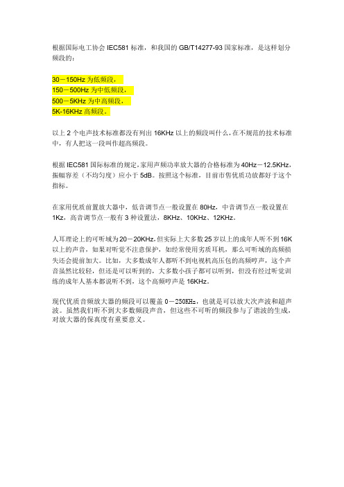
根据国际电工协会IEC581标准,和我国的GB/T14277-93国家标准,是这样划分频段的:
30-150Hz为低频段,
150-500Hz为中低频段,
500-5KHz为中高频段,
5K-16KHz高频段。
以上2个电声技术标准都没有列出16KHz以上的频段叫什么,在不规范的技术标准中,有人把这一段叫作超高频段。
根据IEC581国际标准的规定,家用声频功率放大器的合格标准为40Hz-12.5KHz,振幅容差(不均匀度)应小于5dB。
按照这个标准,目前市售优质功放都好于这个指标。
在家用优质前置放大器中,低音调节点一般设置在80Hz,中音调节点一般设置在
1Kz,高音调节点一般有3种设置法,8KHz、10KHz、12KHz。
人耳理论上的可听域为20-20KHz,但实际上大多数25岁以上的成年人听不到16K 以上的声音,如果对听觉不注意保护,如经常使用劣质耳机,那么可听域的高频损失还会提前加大。
比如,大多数成年人都听不到电视机高压包的高频哼声,这个声音虽然比较轻,但还是可以听到的,大多数小孩子都可以听到,但没有经过听觉训练的成年人基本都说听不到,这个高频哼声是16KHz。
现代优质音频放大器的频段可以覆盖0-250KHz,也就是可以放大次声波和超声波。
虽然我们听不到大多数频段声音,但这些不可听的频段参与了谐波的生成,对放大器的保真度有重要意义。
- 1、下载文档前请自行甄别文档内容的完整性,平台不提供额外的编辑、内容补充、找答案等附加服务。
- 2、"仅部分预览"的文档,不可在线预览部分如存在完整性等问题,可反馈申请退款(可完整预览的文档不适用该条件!)。
- 3、如文档侵犯您的权益,请联系客服反馈,我们会尽快为您处理(人工客服工作时间:9:00-18:30)。
(d)丙类 class-C amplifier
3.要解决的问题 提高输出功率
提高转换效率
管子的保护
减小失真(线性度)
C
输出功率 直流电源提供的直流功
率
=
Po P
=
Po Po PC
P (直流电源功率 ) = Po (交流功率 ) PC (直流功耗 )
5
4. 效率与失真矛盾的解决
丙类(C类) 放大器的效率很高,但是波形失真也很严重。
Icmn cosnt
谐振回路
13
vCE VCC Vcm cos t
iC Ic0 Icm1 cost Icm2 cos2t
Icmn cosnt
直流功率: P==VCC Ic0
输出交流功率:Po
1 2 Vcm
Icm1
集电极效率:
Vc2m 2Rp
1 2
I c2m1 Rp
c
Po P
1 2
(qc
)
其中: 尖顶余弦脉冲的分解系数
0
(qc
)
sinqc qc cosqc (1 cosqc )
1
(qc
)
qc cosqc sinq (1 cosqc )
c
n
(qc
)
2
sin
nqc cosqc n cos nqc sin n(n2 1)(1 cosqc )
qc
21
图5.3.3 尖顶余弦脉冲
化的情况,从而选择合适的工作状态。
c
Po P
1 VcmIcm1 2 VCC Ic0
1 2
1(qc ) n (qc )
1 2
g1
(q
c
)
n
1 0
1
g1 (q c
)
1(qc ) 0 (qc )
qc cosqc sinqc sinqc qc cosqc
0.5 0.4 2.0
0
由曲线可知:极端情况qc=0时, 0.3
1 T
T
0 iC vCEdt
1. iC 与vBE同相,与vCE反相;
2. iC 脉冲最大时,vCE最小; 3. 导通角和vCEmin越小,Pc越小;
电路正常工作(丙类、谐振)时,
外部电路关系式:
v BE VBB Vbm cost
vCE VCC Vcm cost
iC Ic0 Icm1 cost Icm2 cos2t
临界:Po最大,ηc较高; 发射机末级
最佳工作状态
28
1. Vcc对工作状态的 影响——集电极调制特性
改变VCC,但Rp、Vb、VBB不变当集电极供电电压VCC由大至小变化时, 放大器的工作状态由欠压经临界转入过压。
在欠压区内,输出电流的振幅 基本上不随VCC变化而变化, 故输出功率基本不变;而在过 压区,输出电流的振幅将随 VCC的减小而下降,故输出功 率也随之下降。
1
(q
c
)
q
c
cosqc sinqc π(1 cosqc )
0.5
n
(qc
)
2
sin
nqc cosqc n cos nqc sin n(n2 1)(1 cosqc )
qc
0.4 2.0
当qc≈120时,Icm1/iCmax最大。
在 iCmax 与 负 载 阻 抗 Rp 为 某 定 值 的
0.3 0.2 1.0
高频区:0.2 fT f fT
故直接进行高频区或中频区的分析和计算
是相当困难的。本节将从低频区的静态特 0.5fβ 性来解析晶体管的高频功放的工作原理。
fβ 0.2fT
fT
16
为了对高频功率放大器进行定量分析与计算,关键
在于求出电流的直流分量Ic0与基频分量Icm1。
最好能有一个明确的数学表达式来显示二者与通角
Vcm
I
cm1
VCC Ic0
1 2
g1
(q
c
)
集电极电压利用系数 Vcm
波形系数
g1(qc )
Icm1 Ic0
VCC
14
5.3.1 晶体管特性曲线的理想化及其解析式 5.3.2 集电极余弦电流脉冲的分解 5.3.3 高频功率放大器的动态特性与负载特性 5.3.4 各极电压对工作状态的影响 5.3.5 工作状态的计算(估算)举例
gd vCE V0
Vcm Icm1Rp
gd
gc
Vbm Vcm
;
V0 VCC Vcm cosqc
qc
25
2. 高频功放的负载特性
I cm1 Ic0
Vcm
0
欠压
临 界
过压
Hale Waihona Puke RpPo1 2
VcmI
cm1
c
Po P
P VCC Ic0
Pc P Po
0
欠压
临 界
过压
Rp
临界区 欠压区
iC
过 压 区
Rp和VCC 、VBB、Vbm 所表示的输出动态负载曲线。
ic
vCE VCC Vcm cost
A
•
gd
Vo vcmin
Vcm1
v BE VBB Vbm cost
v BE
VBB
Vbm
VCC vCE Vcm
VCC
•Q
vce
iC gc VBE VBZ
iC
gc
Vbm Vcm
vCE
V0
因此,高频功放采用负电源作基极偏置。
iC 转移
特性
失
iC
真
图 5.2.1 高频功率放大器的 基本电路
VBB
理想化
t
- qc
o V BZ
vbe - qc 0 +qc
+ q0c
vbe
V bm
t
v BE VBB Vbm cost
10
iC
iC
DiC Q
0
0
0 u BE
t
UBEQ
ui=Uimcoswt
(a)静态工作点处于放大区
Icm1 iC max1(qc )
cosqc
VBB VBZ Vbm
Vcm Icm1Rp
因此,下面分析四个参数Rp和电压VCC 、VBB、Vbm的变化对工作
状态的影响,即谐振功放的动态特性,从而阐明各种工作状态
的特点,为工作状态的调整提供参考。
24
1. 高频功放的动态特性:为一直线
下面通过折线近似分析法定性分析其动态特性,首先,建立由
7
高频谐振功率放大器 功能:将直流功率转换为交流信号功率。 主要指标:输出功率与转换效率 工作状态:丙类大信号的非线性状态(非线性失真) 分析方法:折线近似分析法。(大信号)
8
5.2.1 获得高效率所需要的条件 5.2.2 功率关系
9
小信号谐振放大器与丙类谐振功率放大器的区别之处在于:
工作状态分别为小信号甲类与大信号丙类。
15
由于高频功放工作在大信号的非线性状态,显然晶体管的小信
号等效电路的分析方法已不适用,所以分析方法一般利用晶体
管的静态特性曲线,但由于晶体管的静态特性曲线与频率有关,
如右图所示了 与 f 之间的关系。而通常所说的静态特性曲线
是指低频区: f 0.5 fβ
β0
中频区: 0.5 fβ f 0.2 fT
0.1
情况下,输出功率将达到最大值。
0
1 0
1 0 2
3
140
100
但此时放大器处于甲乙类状态,
20 40 60 80 120 160180 qc
效率太低。 ICm1 iCmax1(qc )
P0
1 2
I c2m1 Rp
尖顶脉冲的分解系数
22
下面分析基波分量Icm1、集电极效率ηc和输出功率Po随通角qc变
iC Ic0 Icm1 sin t Icm2 sin 2t Icmn sin nt
0 ω 2ω 3ω
6
nω
4. 效率与失真矛盾的解决
通过谐振负载,从丙类余弦周期脉冲里恢复基波完整周期信号。 窄带谐振放大器
有源器件 丙类
谐振回路
输出回路 输入回路 晶体管
35
Tr1 T
L2
C1 4
yL
Tr2
g1(qc )
1(qc ) 0 (qc )
2
Icm1 iCm ax 1(0) 0 0.2 1.0
0.1
1 0 2
3
140
如果此时=1,c可达100%。
0
100
20 40 60 80 120 160180 qc
为了兼顾功率与效率,最佳通角取
图5-9 尖顶脉冲的分解系数
70左右。
23
集电极效率ηc和输出功率Po是否能最佳实现最终取决于功放 中外部电路参数Rp和电压 VBB、Vbm 、 VCC 。
11
t
非线性工作状态的晶体管 集电极电流与静态工作点、 输入信号大小的关系
或电压 电流
vCE VCC Vcm cost
V cm vCE
iC i vCE min
c max
VCC
iC
V BZ
0 qc
-V BB
V bm vBE
v BE VBB Vbm cost
(b)
12
v bEmax
t
c
Po P
Pc
BW 20k 2 f0 10k
高频(射频): 高频窄带信号 (以调幅为例 )
已调信号 vo (t) Vom 1 mf cos t cost ω
AM广播信号: 535kHz~1605kHz,BW=9kHz