基于单片机的智能型浴室混水阀控制器的设计
基于STC89C58单片机淋浴节水控制器设计

基于单片机的智能浴室设计
摘要本课题设计主要以单片机为控制核心的智能浴室温控系统,该课题融合了单片机技术、传感器技术、液晶显示技术等。
整个系统的主要控制核心是单片机,由单片机负责控制DS18B20温度传感器的初始化,再运用DS18B20温度传感器采集浴池水的温度,最后再交给单片机来处理。
在给予准确的设定温度后,由单片机控制进行加热。
在洗浴过程中,当水温低于所设定温度的范围则继续加热,如果水温过高并达到威胁人身安全的时候,该系统会自动停止,并发出报警。
在如今高速运转的智能化时代,人们对卫浴产品的追求也随之提高,而该系统设计也主要运用在家庭及个人的小型浴室中,该系统不仅进行了基于单片机智能浴室控制系统设计的硬件设计,而且针对硬件平台进行了软件开发,为了达到预期的目标,该课题进行了一定的仿真,其中包括硬件电路、软件程序等。
关键词单片机温度显示控制智能浴室AbstractThis topic is designed primarily for the control of a microcontroller core smart bathroom temperature control system, which combines topics microcontroller technology, sensor technology, LCD technology. The main control system is the core of the microcontroller, the microcontroller controls the initialization DS18B20 temperature sensor , then use DS18B20 temperature sensor acquisition bath water temperature , and finally to the microcontroller to handle . After giving an accurate set temperature, heated by the SCM . In the bathing process, when the water temperature is below the set temperature range will continue to heat , if the water temperature is too high and threaten the personal safety when reached , the system will automatically stop and alarm . In today's era of high-speed operation of the intelligent people on the pursuit of bathroom products also will increase , and the system design is mainly used in household and personal small bathroom , the system will not only be based on single-chip intelligent control system design bathroom hardware design, and hardware platform for software development , in order to achieve the desired objectives , the subject for a certain simulation, including hardware circuits, software programs, etc.Key words Temperature display control electric box目录第1章绪论 (3)1.1 课题背景及研究意义 (3)1.2本论文的研究内容和组织结构 (3)第2章设计方案的论证与选择 (4)2.1 设计方案论证 (4)2.2 元器件及其开发软件简介 (4)2.2.1 单片机的选型与简介 (4)2.2.2 显示器件的选型与简介 (6)2.2.3 温度传感器DS18B20的简介 (8)2.2.4 Keil及其开发流程简介 (9)2.2.5 PROTEL简介 (9)2.3 整体设计方案 (10)2.4 本章小结 (11)第3章系统硬件设计 (12)3.1 统总体设计 (12)3.1.1 系统设计方框图 (12)3.2 硬件电路分模块设计 (13)3.2.1 单片机最小系统电路 (13)3.2.2 LCD显示模块 (14)3.2.3 串口电路 (15)3.2.4 温度传感器电路 (16)3.2.5 温度报警电路 (17)3.2.6 电源供电电路 (18)3.2.7 功能按键电路 (19)3.2.8 LED闪烁报警电路 (20)3.2.9 继电器控制电路 (20)3.3 本章小结 (21)第4章系统软件设计 (21)4.1 主程序设计流程 (22)4.1.1 读取温度子程序 (23)4.1.2 计算温度子程序 (24)4.1.3 显示数据刷新子程序 (25)4.1.4 温度控制子程序 (26)4.2 本章小结 (27)第5章系统的仿真 (288)5.1 Proteus简介 (28)5.2 系统的仿真 (28)5.3本章小结 (31)第6章总结 (32)参考文献 (33)附录1:DS18B20显示温度程序 (34)附录2:系统硬件电路 (38)附录3:系统仿真图 (39)第1章绪论1.1 课题背景及研究意义利用单片机的智能浴室有利于处在现代快速发展社会的人群,在下班后去除一身的疲惫和桑拿带来的享受,但是怎样运用单片机技术来实现智能浴室的操控?随着计算机智能技术的发展,特别是微型计算机技术的发展,利用单片机开发智能型浴混水阀控制器实现对出水口水温、水流速度以及淋浴头水流方式的控制具有实际的使用价值,同时具有桑拿时室温、时间、电话以及休闲MP3等功能,对推进人们的健康生活与家居智能化以及节水都具有现实意义。
智能型浴室混水阀控制器的设计毕业设计
智能型浴室混水阀控制器的设计毕业设计智能型浴室混水阀控制器的设计中文摘要随着科技的发展和社会的进步,高新技术正在逐渐改变着人们的生活习惯,其中重要的一个方面就是,使家居呈现智能化。
目前的家居生活中,大部分人仍使用着传统的机械式淋浴系统,这种系统不仅易于损坏,而且由于手动调温的不准确性,还易使皮肤烫伤。
因此设计出能够自动调节水温的家居用品来满足人们的需求、推进人们的健康生活以实现家居智能化具有重要意义,基于此点,课题设计了智能型浴室混水阀控制器来满足这一要求。
在此次设计中,系统以80C51单片机为核心控制器件,由温度采集模块、键盘模块、数码显示模块、步进电机模块和主控制芯片5个部分组成。
使用C语言进行程序的编写,通过使用Proteus进行仿真,经过多次的实验达到了毕业设计的基本要求。
当系统运行时,由单片机对温度采集模块的输出量进行收集,按下启动键,单片机通过读取变量和设定量进行比较,然后把输出量转换成控制信号,控制步进电机并通过数码管显示设定水温和出口水温。
关键字:DS18B20;矩阵键盘;80C51;步进电机;Proteus;C语言The Design of Intelligent Bathroom Mixing Water Valve Controller ABSTRACTNew technology has entered the house gradually and make household intelligent in new era. In people's home life, most people still use traditional mechanical shower systems that easily be damaged andtemperature can not be regulated accurately and also easily burn the user’s skin.In a bid to enable the bathroom intelligent, we design theintelligent bathroom mixing water valve to meet people’s need. This design has much practical significance in pushing f orward people’s healthy life and household intelligence.The system of which the single-chip 80C51 is used as centre control part, consists of temperature collection module, keyboard module,digital display module, stepping motor module and main control chip five parts. C language used in the preparation process, through the use of simulation Proteus, after a number of experiments designed to meet the basic requirements for graduation.When the system is running, the temperature acquisition by the SCM module output for the collection, press the start button, read through the SCM set of variables and comparisons, and then converted to output control signals, control stepper motor and through the display ofdigital temperature settings and export the water temperature.KEYWORD:DS18B20;Matrix keyboard;80C51;Step motor;Proteus;C language 目录第一章前言 ..................................................................... ...................................................................1 1.1论文的来源及研究背景.................................................................................................................1 1.2传统式机械混水阀...................................................................... .. (1)1.2.1传统式机械混水阀的工作原理...................................................................... .. (1)1.2.2传统式机械混水阀存在的问题...................................................................... .......................2 1.3.智能型浴室混水阀 ..................................................................... .. (2)1.3.1智能型浴室混水阀控制器基本组成及其工作原理 (2)1.3.2 研究内容 ..................................................................... ......................................................3 第二章系统方案的选择及论证...................................................................... . (4)2.1 系统的功能要求 ..................................................................... .....................................................4 2.2 各模块方案选择及论证 ..................................................................... . (4)2.3.1单片机...................................................................... . (4)2.3.2键盘输入模块 ..................................................................... (4)2.3.3温度显示模块 ..................................................................... (5)2.3.4温度采集模块 ..................................................................... (5)2.3.5执行机构 ..................................................................... . (5)2.3.6 系统的硬件框图 ..................................................................... ............................................6 第三章硬件电路的设计与实现 ..................................................................... (7)3.1单片机 ..................................................................... .. (7)3.3.1 80C51简介...................................................................... (7)3.1.2 80C51内部结构...................................................................... ............................................9 3.2键盘输入模块...................................................................... . (11)3.2.1键盘接线和按键功能分配...................................................................... . (11)3.2.2键盘的扫描原理...................................................................... (11)3.2.3 键盘的工作方式 ..................................................................... .......................................... 12 3.3温度显示模块...................................................................... . (13)3.3.1 LED显示原理 ..................................................................... . (13)3.3.2 串行显示电路和74LS164简介 ..................................................................... ..................... 14 3.4温度采集模块...................................................................... ....................................................... 15 3.5执行机构模块...................................................................... . (16)3.5.1步进电机简介 ..................................................................... . (16)3.5.2步进电机动态指标及术语...................................................................... . (17)3.5.3 步进电机在控制上的特点 ..................................................................... . (17)3.5.4步进电机细分驱动器原理...................................................................... . (18)3.5.4 L297和L298简介 ..................................................................... (18)3.5.5 L297和L298构成的驱动电路...................................................................... ..................... 20 第四章系统软件设计与仿真 ..................................................................... (21)4.1 软件开发与仿真调试环境和开发语言介绍 ..................................................................... ............. 21 4.2系统软件设计思想...................................................................... ................................................ 21 4.3 子程序描述及其流程图 ..................................................................... .. (22)4.3.1 温度读取子程序 ..................................................................... (23)4.3.2 键盘扫描子程序 ..................................................................... (23)4.3.3 步进电机升降温控制子程序 ..................................................................... (24)4.4.4 系统总体仿真图 ..................................................................... (25)总结 ..................................................................... ........................................................................ ..... 26 致谢 ..................................................................... .................................................错误~未定义书签。
基于单片机淋浴水温调节器设计 毕业论文
基于单片机淋浴水温调节器设计毕业论文淋浴水温调节器设计摘要目前淋浴热水器在家庭中运用越来越广泛,然而市面上存在的淋浴调节方式主要是通过手动调节开关量的大小来控制水温的高低。
这种调节方式不能够很好的控制水温的高低,有时由于调节开关距淋浴地点较远,给人们调节水温带来不便,因此,这种调节方式不能够满足人们追求生活舒适的要求。
本论文介绍了一种以单片机为主要控制器件,以DS18B20为温度传感器的新型淋浴水温调节器。
主要包括硬件电路的设计和软件设计。
硬件电路主要包括主控制器,测温控制电路和显示电路等,主控制器采用单片机STC89C54RD+,温度传感器采用DS18B20,显示电路采用8位共阴极LED数码管动态扫描显示。
测温控制电路由温度传感器和预温度电路组成,当实际测量温度值大于或小于预置温度值时,发出信号,从而发出指令控制冷水口和热水口的阀门,使热水和冷水进入到一定大小的容器,保证容器的水温在一定范围内变化。
软件设计主要包括主程序,测温子程序和显示子程序等。
该设计能够实现精确控制水的温度,其中由于单片机的集成化,使产品小型化、智能化,既提高了产品的功能和质量,又降低了成本,简化了设计。
关键词:STC89C54RD+,DS18B20,显示电路,测温控制电路 Shower water temperature regulator design ABSTRACT Shower water heater is currently more widely used at family, however, there is a mainly way to regulate shower which through manual adjustment switch to controlthe temperature in the market . This adjustment is not a good way to control the temperature , and sometimes regulating switch is far away from the shower location, which is not convenience to control the temperature. therefore, this adjustment method is not able to satisfy the people to pursue life comfortable request.This paper introduces a kind of new shower water temperature regulator, which use the Single chip as the main control device and DS18B20 as the temperature sensor. It mainly includes hardware circuit design and software design. Hardware circuit mainly includes the main controller, temperature control circuit and display circuit , the main controller uses the Single chip STC89C54RD +, temperature sensor adopts DS18B20,display circuit uses eight total cathode tube dynamic scanning LED digital display. Temperature control circuit is consist of temperature sensor and the preset temperature comparison circuit, and when the actual measured temperature greater than or less than the preset temperature value, a signal to send commands to control the mouth of cold water and hot water valve port, so that hot and cold water into the container to a certain size, to ensure that the temperature of the container changes a certain range. Software design mainly include main program, temperature program and display program. This design can achieve precise control the temperature of the water in which the integrated single chip make the product miniaturization and intelligent, not only improves the functionand quality of products but also reduces the cost and simplify the design. KEY WORDS: STC89C54RD +,DS18B20,Display circuit, Temperature control circuit 目录前言 1第1章设计任务及方案设计 2§1.1 设计任务及要求2§1.2 设计总体方案及论证 2§1.3 设计总体框图及结构图 2第2章硬件设计 4§2.1 单片机核心模块4§2.1.1 单片机类型及接口的选择 4§2.1.2时钟电路的设计 5§2.1.3复位电路的设计 6§2.2 电源电路模块 6§2.3 按键模块7§2.4 温度采集模块8§2.4.1 温度传感器的选择8§2.4.2 DS18B20芯片的特点8§2.4.3 DS18B20芯片的内部结构及引脚9§2.4.4 DS18B20与单片机接口电路10§2.5 继电器模块 10§2.6 显示模块11§2.6.1 LED指示灯显示电路11§2.6.2 八位共阴极数码管显示电路12§2.7 PCB设计13第3章系统软件设计15§3.1 各部分软件介绍15§3.1.1 DS18B20温度采集程序15§3.1.2 显示程序 17§3.1.3 按键程序 17§3.2 软件总程序 17第四章系统调试19结论20参考文献21致谢22附录23附录1:整体电路原理图23附录2:PCB印制版电路图 24 前言随着科技的进步,人们的生活水平日益提高,人们对家庭生活中的舒适要求也越来越高。
基于单片机的智能型混水阀控制系统的研制
g r e a t e r r o r. Th i s d e s i g n US E S t h e k e y b o a r d s e t t e mp e r a t u r e, t h r o u g h DS1 8 B2 0 t e mp e r a t u r e s e n s o r t o me a s u r e t h e c ur r e n t wa t e r t e mp e r a t u r e , t h e t wo t e mp e r a t ur e t h a n i n t h e p r o g r a m o f s i n gl e -c hi p mi c r o c o mp u t e r t o c o n t r o l s t e p p i n g mo t o r d r i v e s t h e mi x wa t e r v a l v e o f s h i f t a n d r o t a t i o n, u nt i l t he s e n s o r t o me a s u r e t he wa t e r t e mp e r a t u r e i s e q u a l t o t h e p r e s e t t e mp e r a t u r e, t h e mo t o r s t o p r u nn i n g t o g e t t h e r e q u i r e d wa t e r t e mp e r a t u r e v i e w o f r e s e a r c h a nd p r a c t i c e, p u t f o r wa r d t h e c o r r e s p o n d i n g r e f o r m e x p e r i e n c e o f
基于传感器和单片机的权控智能节水器设计

随着社会和经济的不断发展,环境和资源问题日益突出,预计到2020年,全国年总需水量将达到900亿立方米,而缺水量也将达到150亿立方米,水资源短缺已成为制约我国经济和社会发展的重要因素,为此国家大力提倡节能减排,鼓励节水、节能设备的研发。
卫生间节水技术始于20世纪80年代末和90年代初期,在节水技术初级阶段,普遍采用数字逻辑电路和模拟电子技术实现节水控。
随着社会和经济的不断发展,环境和资源问题日益突出,预计到2020年,全国年总需水量将达到900亿立方米,而缺水量也将达到150亿立方米,水资源短缺已成为制约我国经济和社会发展的重要因素,为此国家大力提倡节能减排,鼓励节水、节能设备的研发。
卫生间节水技术始于20世纪80年代末和90年代初期,在节水技术初级阶段,普遍采用数字逻辑电路和模拟电子技术实现节水控制功能;自21世纪以来,卫生间节水技术开始采用先进的红外检测技术以及单片机控制技术,节水率有了较大的提高。
目前卫生间节水设备存在诸多技术上的缺陷,即冲厕不及时,误冲厕、漏冲厕现象频繁,导致节水率低,环境卫生差。
为实现节约型、环保型社会,未来的卫生间节水设备必将朝着高节水率、环保、集成化、智能化方向发展。
基于此,设计了一种基于统计学和模糊控制理论的权控智能节水系统。
它利用改进的红外检测单元准确地采集数据;以AT89C2051单片机为硬件平台构建信号处理、控制的主控制器,对检测数据进行处理,并实时判断出真实的人流量;注水分主注水和权控注水,保证主控制单元发出冲厕指令后能迅速冲厕。
试验结果表明,系统各项性能指标均达到设计要求,节水率提高到88%。
1、权控技术为了确保主控制单元发出冲水指令后,水箱内的水能迅速泻放,本节水系统采用了权控技术,权控冲厕功能由主注水、防渗漏控制单元、主控制单元等实现。
主注水单元依据水箱低水位检测器状态判断出水箱全空时启动电磁阀,执行主注水至水箱总容量的95%时停止,为水箱的低水位。
智能型浴室混水阀控制器的设计
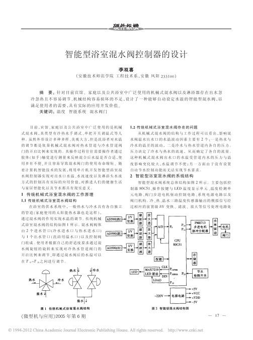
! 传统机械式浴室混水阀的工作原理
!"! 传 统 机 械 式 浴 室 混 水 阀 结 构
在浴室 的 供 水 系 统 中 !一 般 热 水 与 冷 水 具 有 各 自 独 立 的 管 道 % 家 庭 使 用 的 太 阳 能 热 水 器 也 是 这 样 &! 通过混水阀的作用实现水温的调节$ 传统机械 式浴室混水阀的结构如图 ! 所示$ 混水阀阀体 由 " 个进水管口#冷水进水口与热 水 进 水 口$ 与 ! 个出水 管 口 %洗 浴 用 温 水 口 &以 及 控 制 阀 门组成$ 使用者根据自己的舒适度要求通过混 水阀旋钮的旋转来实现对冷热水管道阀门的 开 启 比 例 来 调 节 !即 通 过 混 水 阀 后 的 水 温 可 以 在 ! 冷 !!
智能型浴室混水阀控制器的设计
! 安徽技术师范学院 工程技术系 " 安徽 凤阳 !""#$$ #
摘
要 ! 针对目前宾馆 $ 家庭以及公共浴室中广泛使用的机械式混水阀以及淋浴 器 存 在 出 水 忽
冷忽热且不容易调节 $ 机 械 结 构 容 易 损 坏 的 不 足 " 设 计 了 一 种 能 够 自 动 设 定 水 温 的 智 能 型 混 水 阀 " 以 满足使用者的需要 " 具有实际的应用开发价值 % 关键词 ! 温度 智能系统 混水阀门
需 要 ! 选 用 串 型 % 位 *+# 驱 动 器 3!C91). 7 18 作 为 *+# 显 示 驱 动 器 件 $ 3!C91). 器 件 内 置 D’# 码 译 码 器 % 多 路 扫 描电路%段及数字驱动器和用于存储每一位显示数据的 静 态 5!3 ! 使 用 十 分 方 便 $ 3!C91). 具 有 ) # % 位 数 据 显 示 选择功 能 ! 因 此 很 容 易 适 应 系 统 显 示 ; 位 数 的 需 要 $ 温 度 数 据 从 %&’() 的 6,-& ) 5C# ( 串 行 口 输 出 到 *+# 驱 动 器
基于STC89C58单片机淋浴节水控制器设计

如图 4 所示。
SST29SF040 是一个 512K×8 的 CMOS 多功能并
行 SSF 器件,可进行快速擦除(扇区、块、芯片擦除)
和字编程,具有软、硬件写保护功能,掉电数据保持
时间大于 100 年。 在本控制器中,用于离线存储用户
刷卡消费的记录,包括刷卡时间、卡号、消费金额、累
计消费金额等,也可将记录上传至上位机进行管理。
MCU 触发一次外部中断 INT0。 在中断服务程序中, 通过读取数据线上的内容获取卡号。
13.56M
200μF 200μF
47μF
IRQ
OSCIN IRQ
OSCOUT TX2
TX_OUT2 接
VCC
A0Biblioteka A1TX127μF TX_OUT1 天 线
ALE CS WR RD RST
A2 ALE
RC500
FM24CL64 是一个具有 8K 字 节 存 储 空 间 的 串
行 CMOS E2PROM,通过 I2C 总线接口进行操作,有
一个专门的写保护功能。 该芯片占据的 MCU 的 IO
资源较少,编程简单,数据存储可达 100 年[3]。 在本
仪器中,用于实现配置参数、通信参数、过程参数、中
间变量等的保存。
该模块 由 Philips 公 司 生 产 的 高 集 成 读 卡 芯 片 MF RC500 构成,如图 3 所示,完成对 IC 卡内 金 额 的读写操作。
MF RC500 是应用于 13.56MHz 非 接 触 式 通 信 中高集成读卡 IC 系列中的一员,其内部的发送器部 分不需要增加有源电路,就能够直接驱动近操作距 离的天线。 同时,方便的并行接口可直接连接到任 何 8 位微处理器,这样给读卡器终端的设计提供了 极大的灵活性[2]。 当用户刷卡时,通过 IRQ 引 脚 向
基于单片机游泳池温度控制系统的设计
洛陽理工學院游泳池水温控制系统设计课程答辩王明超2014/12/29班级:B110411学号:B********姓名:***摘要随着人民生活的进步,恒温游泳池走进了我们的生活,而游泳池的保温控制器,它能自动控制游泳池的水温。
从而大大的方便了人们对游泳池水温恒温的需求。
本文对该测控仪系统进行了分析设计。
本游泳池恒温控制系统选用AT89C51单片机作为控制器,利用PID和PWM技术实现对游泳池的水温控制。
该控制系统主要由CPU主控制模块、主电源模块、键盘处理模块、温度采集模块、继电器控制模块及LED显示模块构成。
本游泳池恒温控制系统选用AT89C51单片机作为控制器,利用PID和PWM技术实现对游泳池的水温控制。
该控制系统主要由CPU主控制模块、主电源模块、键盘处理模块、温度采集模块、继电器控制模块及LED显示模块构成。
DS18B20用来采集温度信号,其体积小,精度高,适用电压宽,抗干扰能力强。
继电器控制两台电机的转动,分别对应控制热水阀和冷水阀,从而,实现水温的实时控制。
最后,采用共阳极数码管LG5641A动态显示水温。
关键词: AT89C51单片机,游泳池,温度控制,模糊控制。
Ⅰ目录第1章绪论 3 1.1选题的背景与意义 3 1.1.1自动控控系统可温度控制系统 3 1.2 温度控制系统的设计 3 第2章系统总体设计 4 2.1方案的选择 4 2.2系统总体设计 4 第3章硬件设计 5 3.1硬件选型 5 3.2硬件电路设计 5 3.2.1主电源电路 5 3.2.2温度采集模块 6 3.2.3按键输入电路 6 3.2.4继电器模块 7 3.2.5 显示模块 7 第4章软件设计 8 4.1系统程序设计 8 4.2各部分程序流程图 8 4.2.1. 计算温度子程序 9 4.2.2.按键处理子程序 9 4.2.3.计算温度子程序 10第5章仿真结果 12 5.2仿真结果 12 5.1本系统仿真 13 5.2仿真结果 13 结论 14 参考文献 15 附录 16第1章绪论1.1选题的背景与意义1.1.1自动控控系统可温度控制系统电子技术的发展,特别是随着大规模集成电路的产生,给人们的生活带来了根本性的变化,如果说微型计算机的出现使现代的科学研究得到了质的飞跃,那么单片机技术的出现则是给现代工业控制测控领域带来了一次新的革命。
基于单片机的浴室水温控制系统的设计+电路图+源程序

目录摘要 (1)Abstract (2)1 引言 (3)1.1 论文的选题背景及意义 (3)1.1.1 国内外发展情况 (4)2 浴室水温控制系统基本原理 (6)2.1 浴室水温控制系统总体架构 (6)2.2 浴室水温控制系统各部分功能 (6)2.2.1 主控微处理器部分 (6)2.2.2 电源部分 (8)2.2.3 调试及接口外扩部分 (8)2.2.4 串口通信部分 (8)2.3 DS18B20水温传感器部分 (9)2.4 浴室水温系统总体设计流程 (12)3 浴室水温控制系统硬件设计 (15)3.1 最小系统硬件功能介绍 (15)3.1.1 供电电路 (15)3.1.2 微处理器电路 (16)3.1.3 USB转TTL-UART电路 (17)3.1.4 按键电路 (18)3.1.5 LED指示灯电路 (18)3.2 水温传感器电路 (19)4 浴室水温控制系统软件设计 (20)4.1 STM32CubeMX硬件驱动配置软件介绍 (20)4.2 STM32CubeMX硬件底层配置 (21)4.3 生成底层硬件的驱动代码 (25)5 恒温系统应用逻辑代码实现 (27)5.1 Keil-MDK5软件介绍 (27)5.2 用户逻辑代码实现 (28)6 结论 (29)参考文献 (30)附录A 电路图 (31)附录B 源程序 (32)摘要在科学技术不断发展,人民生活水平的不断提高的现代,洗浴也成了人们日常生活必不缺少的一部分,人们对于洗浴产品的追求也随之提高。
目前,市面上的太阳能热水器,使用时调节温度就显得极为不方便,对于浴室的水温的要求,只可以通过浴室水阀来调节水温,用来满足相应的对水温舒适度的需求,但是这种温度调节是人为的不断调节的结果,人们在洗浴的过程还要考虑到水温的变化,这就给洗浴造成了不舒适感。
基于此种情况,本课题使用温度传感器DS18B20实时测量水温,微处理器STM32F103C8T6采样水温值,并根据水温值的实时变化合理调节冷热水的进水量,当水温低于所设定温度的范围则继续加热水,如果水温高出所设定温度的范围则加凉水,使得出水始终保持在舒适的温度,即自动控制浴室水温,避免了频繁人为改变水温的麻烦,同时也在一定程度上减少了能源的消耗。
智能型淋浴器自动混水控制器设计

智能型淋浴器自动混水控制器设计摘要由于国民经济的飞速发展,大量的热水器已经普及。
但是,许多消费者发现热水器有冷热缺陷,并且保持恒温的时间很短。
市场上的热水器只能执行一些基本功能,例如远程控制,并且不能在固定的时间内进行分析。
认识到人类的行为来控制热水器的温度。
本文分析了现代恒温器控制方法存在的问题。
为解决电热水器恒温控制方法的问题,采用了基于布尔代数的逻辑控制算法,并提出了七种控制策略。
基于该算法,控制步进电机,通过步进电机调节恒温混合阀的冷热水供应,使最终温度稳定地达到用户设定的温度。
实验结果表明,布尔代数恒温算法在相似方法中可以将指定范围内的恒温保持更长的时间。
关键词:温度控制;沐浴器;智能控制目录1 绪论 (1)1.1 课题研究背景 (1)1.2 论文主要研究内容 (1)2 智能型淋浴器关键技术分析 (2)2.1 数据分析技术 (2)2.2 热水器恒温原理 (3)3 智能型淋浴器的分析与研究 (4)3.1 智能型淋浴器用户需求分析 (4)3.2 智能型淋浴器的恒温控制研究 (4)3.3 智能型淋浴器的整体结构 (6)4 智能型淋浴器硬件设计 (7)4.1 智能型淋浴器硬件整体设计 (7)4.2 智能型淋浴器分系统模块 (7)4.2.1 智能型淋浴器的主控系统 (7)4.2.2 智能型淋浴器的无线系统 (9)4.2.3 智能型淋浴器的显示系统 (9)5 智能型淋浴器应用设计 (11)5.1 智能型淋浴器的嵌入式终端应用设计 (11)5.1.1 软件开发环境 (11)5.1.2 嵌入式终端应用设计 (11)5.1.3 恒温控制应用设计 (12)5.2 智能型淋浴器的移动客户端应用设计 (14)5.3 本章小结 (16)6 总结 (17)参考文献 (18)1 绪论1.1 课题研究背景最近几年由于房地产行业的突飞猛进,热水器行业出现了产能过剩问题,如果希望未来热水器行业能够健康稳定的发展,就必须对热水器在环保、安全和智能方面进行改造[3]。
基于单片机的智能型浴室混水阀控制器的设计--初稿

学校代码:11059学号:0605074001Hefei University毕业论文(设计)BACH ELOR DISSERTATI ON论文题目:基于单片机的智能型浴室混水阀控制器的设计学位类别:______________________工学学士___________________________ 学科专业:______________________自动化___________________________作者姓名:______________________刘涛___________________________ 导师姓名:______________________孙强_____________________________ 完成时间:_________________2010年5月18日_____________________基于单片机的智能型浴室混水阀控制器中文摘要随着信息技术的飞速发展以及人们生活水平的大幅度提高,人们对生活的需求已从追求简单向着追求质量,功能,服务等多重需求过渡。
在冬天,热水器是人们使用很频繁的家用电器,但传统的机械式混水阀的对水温的调节操控性并不是很好。
因而本设计针对热水器的混水阀控制器进行改进,使其具有自动调节水温的功能以及良好的操控性。
本文采用AT89C52单片机来检测整个系统,温度传感采集水管现场数据,经过信号处理模块对信号进行处理,通过模数转换器,将信号送入单片机,显示处理结果。
硬件部分介绍温度传感器、A/D转换器、单片机、显示模块及步进电机。
软件部分主要介绍设计思想及主程序流程图,系统调试部分包括调试软件、调试过程及调试过程中出现的问题和解决方法。
关键词:混水阀;单片机;温度;传感器Based on Microprocessor Intelligent Controller of Mixing ValveAbstractWith the rapid development of information technology ,people's living standards greatly improved,demanding people seeking a simple life toward the pursuit of quality, functionality and service multiple needs of the transition. In winter, water heater is very frequent the use of household appliances, but the traditional mechanical mixing valve for regulating water temperature is not very good handling. Therefore the design of the mixing valve controller for the water heater to improve, it has the automatic adjustment function of temperature and good handling.In this paper, AT89C52 microcontroller to detect the entire system, water temperature sensing field data collection, through the signal processing module processing the signal through the ADC, the signal into the microcontroller, display processing results. Temperature sensor section describes the hardware, A / D converter, microcontroller, display module and stepper motor. Software design and introduce some of the main program flow chart, system debugging section includes debugging software, the debugging process and the debugging process problems and solutions.Keywords:mixing valve;microcontroller;Temperature;sensor目录第一章绪论 (1)1.1课题研究的背景及依据来源 (1)1.1.1课题研究的背景 (1)1.1.2 课题的依据来源 (1)1.2传统机械式混水阀 (2)1.2.1传统机械式浴室混水阀的工作原理 (2)1.2.2传统机械式混水阀存在的问题 (2)1.3智能型浴室混水阀 (2)1.3.1智能型浴室混水阀控制器的基本组成 (2)1.3.2智能型浴室混水阀控制器工作原理 (3)第二章系统方案的设计与论证 (3)2.1系统功能 (3)2.2系统总体方案规划 (4)2.3各模块方案选择及论证 (4)2.3.1中央处理单元 (4)2.3.2键盘输入模块 (4)2.3.3温度显示模块 (5)2.3.4温度采集模块 (5)2.3.5执行机构 (5)第三章主要元器件的设计 (7)3.1AT89C52单片机 (7)3.1.1 功能特性描述 (7)3.1.2 管脚描述 (8)3.1.3 引脚功能 (8)3.2AD590温度传感器 (10)3.2.1 概述 (10)3.2.2 AD590工作原理 (11)3.3ADC0809模数转换器 (11)3.3.1 主要特性 (11)3.3.2 ADC0809工作原理: (12)3.41602字符液晶 (13)3.4.1引脚说明 (13)3.4.2字符集 (15)3.4.3指令集 (16)3.54*4矩阵键盘 (16)3.6步进电机 (17)3.6.1 概述 (17)3.6.2分类 (18)3.6.3基本原理 (18)3.7步进电机驱动芯片L297 (19)3.7.1 概述 (19)3.7.2 L297各引脚功能说明 (20)3.7.3 L297驱动相序的产生 (22)第四章系统硬件设计 (24)4.1扩展外围接口 (24)4.2温度检测电路设计 (24)4.3.1 设计目标 (24)4.3.2 设计的出发点 (25)4.3.4 转换电路 (25)4.3显示电路设计 (26)4.4执行机构的设计 (27)第五章系统的软件设计 (27)5.1系统软件设计思想 (27)5.1.1 系统流程图 (27)5.1.2 冷热水的配比 (28)5.2子程序描述及流程图 (29)5.2.1 系统初始化子程序 (29)5.2.2 A/D转换子程序 (29)5.2.3 键盘扫描子程序 (29)5.2.4 温度显示子程序 (30)5.2.5打开电机子程序 (30)5.3.6 温度控制子程序 (30)5.2.7 水位控制 (31)5.2.8中断子程序 (31)第六章系统调试与仿真 (33)6.1温度采集的调试.................................................... 错误!未定义书签。
课程设计(论文)_基于单片机的淋浴水温控制系统的设计

基于单片机的淋浴水温控制系统的设计摘要:本论文对实际情况进行数学建模,并根据分析和实验的结果设计了控制系统。
利用工业控制的8031单片机搭建控制系统,系统的前向通道未用了成本低、休积小、线性电流传感器,为提高精度,传感器设计了T型滤波器以增加杭干扰能力,单片机应用未用PID葬法的撞制方式担制双向可控硅的导通、关断,调整功率,使之切断或接通加热器,从而控制水温稳定在预设定值上。
系统后向通道采用干扰小、器件运行可靠的过零触发方式,省去了传统的D/A接口电路,简化了硬件设备。
在软件设计中,为提高精度我们采用了数字滤波方案以减少干扰信号的比重。
根据温控的单回路PID数字调节器的硬件设计,完成实时浏重(传感采样)、实时决策((PID控制运算)和实时控制(调功)三部分功能,为防止超调量过大,对PID算法进行了适当改进,用单片机产生PWM波对电机进行控制,调节冷热水管的流量,最终达到控制输出水温的目的。
目录引言 (2)1.设计任务 (2)基本要求 (3)发挥部分 (3)2方案论证 (3)方案一 (4)方案二 (4)方案三 (5)3方案设计 (6)系统工作原理 (6)主要电路设计 (7)软件设计 (9)4性能指标测试: (12)5结论 (13)系统误差分析 (13)参考文献 (14)引言随着自动化技术的进一步发展,现在很多家庭都希望能享受智能化服务的家居环境;人们生活无非衣食住行,对于居住,如果有智能化淋浴设施,更能为生活增色不少,智能化淋浴设施中关键的两项技术为:温度控制与流量控制,其中人们对于温度控制是希望在自己设定数值以后变化不大,仅仅在设定数值周围波动;而流量则直接按需要进行调节。
1.设计任务设计制作一个淋浴水温控制系统,控制对象为1升净水,容器为搪瓷器皿。
水温可以在一定范围内由人工设定,并能在环境温度降低时实现自动调整,以保持设定的温度基本不变。
淋浴水温调节系统由温度传感装置、控制系统、显示装置、冷水流控制装置、热水流控制装置、总流量控制装置构成,如图2-1所示。
基于MCS-51单片机的远程浴室控制系统设计

M C 一 1sn l h p a h y t m o to n t h y t m a d r i u t e i n a d s fwa ed sg n lme t t n S 5 i gec i t es se c n r l i ,t es se h r wa ecr i d sg n o t r e in a d i e n a i s u c mp o o lcr ma n t av n / o v re o to ,t u e l i g t e tmp r t r n a h wa e v le a d A D c n e trc n r l h sr ai n h e e a u e a d b t trd s h r e t c z mec n r 1
TA NG u i H a
【 b rc T ipprn oue a i e a ro n oep n o a y n h n—s ne ot l t t— A s at h ei r c k d fh t omc t lr l r eog iac cn o,h b h t 】 s a t d s n o t b h o rl a t c r o t l d t r ea
[ 中图分类号]T 2 2 P 7 [ 文献标识码]A [ 文章编 号]17 6 4—32 (0 2 0 2 9 2 1 )4—04 0 0—0 3
1 引 言
随着我 国经 济 的快 速发 展 , 民生 活 水平 不 断 人
提高 ,信息 化 ” 概 念 被 引 入 到 了住 宅 的建 设 当 “ 的 中 。本 文设 计 了一 种 可 进 行 远 程 控 制 的 家 用 智 能
基 于 MC 一 片 机 的 远 程 浴 室 控 制 系统 设 计 S5 1单
基于单片机的浴缸水位水温控制系统设计

** 师范学院————————————————信息工程学院毕业设计〔论文〕附属过程管理材料〔2013届〕专业电子信息工程学号0908**学生****师范学院教务处印制目录1. 湖州师范学院本科毕业设计〔论文〕选题审批表2. 湖州师范学院本科毕业设计〔论文〕任务书3. 外文原稿(复印件)与译文4. 文献综述〔前言、主题、总结、参考文献〕5. 湖州师范学院本科毕业设计〔论文〕开题报告6. 湖州师范学院本科毕业设计〔论文〕中期检查报告7. 湖州师范学院本科毕业设计〔论文〕指导教师审阅表8. 湖州师范学院本科毕业设计〔论文〕评阅人评阅表9. 湖州师范学院本科毕业设计〔论文〕硬件验收评分表10. 湖州师范学院本科毕业设计〔论文〕答辩记录表11. 湖州师范学院本科毕业设计〔论文〕答辩评分表12. 湖州师范学院本科毕业设计〔论文〕评分表13. 湖州师范学院本科生毕业设计〔论文〕诚信承诺书14. 校级优秀毕业设计〔论文〕推荐表湖州师范学院本科毕业设计〔论文〕选题审批表湖州师范学院毕业设计〔论文〕任务书指导教师〔签名〕**学生〔签名〕**开始执行任务日期2012年6月30毕业设计〔论文〕——外文翻译〔原文〕AN EMBEDDED SINGLE CHIPTEMPERATURECONTROLLER DESIGNJ. Jayapandian and Usha Rani RaviDesign Development & Services Section, Materials Science DivisionIndira Gandhi Centre for Atomic Research, Kalpa Kama – 603 102. Tamil Nadu. IndiaABSTRACTThis paper describes a single chip embedded temperature controller design programmed in a single Programmable System on Chip (PSoC);a mixed array logic consists of analog,digital and digital virtual instrument control program written in Labview ver.7.1,a graphical language,provides user friendly menu driven window based control panel,interacts with the single PSoC chip design for sensing and controlling the temperature.This simple cost effective embedded design finds potential application in laboratory as well as in industries.This deign can also be made as a standalone system without PC by programming LED/ LCD display and key pad attachment modules in same PSoC chip.1. INTRODUCTIONThe advent of intelligent programmable embedded silicon designs provides the ability to implement any required hardware programmatically for the design automation in industries and laboratories.Recent trend in laboratory as well as in industrial automation designs uses programmable embedded components and application software available in the market enables the designer for user friendly cost effective design solution for any system automation.Temperature controllers are playing vital role in industries and laboratories.To accurately control process temperature without extensive operator involvement,a temperature control system relies upon a controller,which accepts a temperature sensor such as a thermocouple or RTD as input.It compares the actual temperature to the desired control temperature,or set point,and provides an output to a control element.The controller is one of the major parts of the entire control system,and the whole system should be analyzed in selecting the proper controller.This paper describes a novel single chip temperature controller design with Cypress Micro systems Programmable System on Chip (PSoC).Virtual instrument control program written in Lab VIEW ver.7.1 interacts with the embedded PSoC design and senses and controls the temperature of furnace / load.2. PROGRAMMABLE SYSTEM ON CHIP (P Soc)While Sand inexpensive interface to sensors,andmore.Cypress’System-Chip(PSoC)architecture offers a flexible,economical solution for a wide variety of applications.This paper how n in fig.1,it features four main areas:PSoC core,digital system,analog system,and resources including in/out ports. This architecture allows the user to create customize Alpheratz configurations that match the requirements of each individual application.The UAR Tinter face, coupled with configurable analog and digital peripherals makes the CY8C27143 truly universal in its connections to the external world.The PSoC core includes:an M8C micro controller;32K Bytes of program flash memory;2Kbyte of data RAM;internal 24 oscillator;sleep and watchdog timer;general-purpose input/output pins (GPIO) allowing any pin to be used as digital input or output,and most pins to be used as analog inputs or outputs.Every pin can be used as a digital or analog interrupt.The digital system is made up of 8digital PSoC blocks.Each block is an 8-bit resource that can be used alone or combined with other blocks to form peripherals.Possible peripherals include:PWMs (8- to 32-bit);PWMs with dead band (8- to 24-bit);counters (8- to 32-bit);UART 8-bit with selectable parity;SPI master and slave;cyclical redundancy checker/generator (8- to 32-bit);pseudo random sequence generators (8- to 32-bit).These digital blocks can be connected to any of the GPIO through a series of globalbuses.These buses also allow for signal multiplexing and performing logic operations.The analog system is made up of12configurable blocks,each comp rising an op amp circuit allowing the creation of complex analog signal flows.Analog peripheral sar of the more common PS0C analog functions are:filters (2 and 4 pole band-pass,low-pass,andnotch); amplifiers (up to 2,with selectable gain to 48x);instrumentation amplifiers (1with selectable gain to 93x); comparators (up to 2, with 16 selectable thresholds);DAC (up to 2, with 6 to 10-bit resolution); and SAR ADC (up to two,with 6-bit resolution).In combination with the digital blocks,additional functions can be created, including: incremental ADCs (up to 2, with 6- to 14-bit resolution); delta sigma ADC (1,with 8-bit resolution at62.5ksps).The additional system resources provide additional capability useful for the complete system design..Fig. 1 : Block diagram of Programmable System on Chip (PSoC) internal blocks3. VIRTUAL INSTRUMENT PROGRAMVirtual instrument (VI) is an application of general purpose digital PCs for the measurement and control of various physical variables.The VI program mimics the control processes,which are in a remote area,on the PC screen.On-going process control automation can be visualized by the experimentalist through PC screen.VI program provides inexpensive and yet a powerful platform for the control and data acquisition of process variables.These programs are easy to implement with graphic languages (G-language).The “G” language implements the data flow technique.The usage of “G” language provides easy interfacing with PCs under the Windows environment [2]. The “G” language provides built-in function libraries for a variety of application requirements as graphic palettes, which in turn supports the required DLL s for the functions to run under windows ually the “G” language VI programs consist of two frames viz.,panel diagram and functional diagram.In the panel diagram,programmers can assign various controls and indicators (i.e., input and output variables).their requirements and in the functional diagram, the designers can implement the required.Fig. 2 : PSoC designer screen for single chip temperature controller Functions available as a function library in Lab.National Instruments version7.1 incorporates all the necessary func tions as ‘icons’ in its package.4. PSoC SINGLE CHIP TEMPERATURE CONTROLLER DESIGNshows the PSoC designer screen for the embedded single chip temperature controller design project [1].Left side of the screen shows the settings portion of the screen shows the analog and digital blocks user module placement.Top portion of the screen shows the selected user modules for this project.Right side of the screen describes the pin connectivity configured in the design.In this novel single chip design,thermocouple (TC) signal has been amplified by a programmable gain amplifier (PGA) placed in the PSoC’s analog block.The amplified TC signal has been fed in to a 12 bit Analog-to digital(ADC) user module programmed in the PSoC chip, which includes both analog and digital blocks for its functionality by PSoC designer programming.The converted digital data of the TC signal has been fed to the UART user module for serial communication with Personal Computer.The UART user module placed in the chip,automatically gets placed in two digital blocks of PSoC chip,transmitter (TxD) and receiver (RxD) for PCs serial communication.A pulse width modulator (PWM),placed in the PSoC digital block,sets a serial pulse width modulated TTL pulses in response to the PID control function for the deviation in set and measured temperature.This will in turn controls the optically coupled solid state relay (SSR) driving the AC line power connected to the load/furnace[3,4].The menu driven window based virtual instrument control program senses the temperature,via,thermocouple,TC amplifier,12-bit ADC and UART communication block of PSoC chip and evaluate the control functions like PID, linear heating, on-sweep and sets the pulse width of PWM in a PSoC chip via UART block in a serial communication.Fig. 3 : Single PSoC chip Temperature controller designFig.3.shows the connectivity of a single PSoC chip design with solid state relay (SSR)and USB port via,serial-to-USB converter cable for communication with PC.The SSR,acts as AC power controller for controlling the furnace power,has been activated by the PWM pulses from PSoC chip.The menu driven virtual instrument control program works in window environment interacts with the embedded design for sensing,controlling and acquiring the temperature data. On-line plotting of acquired temperature data also carried out by the VI program.5. CONCLUSIONA simple and cost effective embedded temperature controller has been designed,fabricated and tested successfully for its functionality.This compact designs permits the user to select any type of control function through its virtual instrument program,written in LabVIEW ,and works under window environment.This design can be directly connected to PCs‘com’ port or USB port via USB-to-serial converter cable,the SSR power controller module can be connected on the furnace stand.The optically isolated power controller provides safe operation without damaging the interfacing intelligent controller. 6. REFERENCES1 J. Jayapandian.Current Science, Vol 90. No.6. 25th March 2006. p.765-770.2.National Instrument’s LabVIEW user manual.Briefs. Electronic Design Magazine. A Penton Publication.New Jersey,USA. ED Online ID #5687.September 15,2003..33 (2) 75 – 80 (2003).出处:J.instrum.soc.india 38(1) 50-54.毕业设计〔论文〕——外文翻译〔译文〕嵌入式单片机温度控制器设计J. Jayapandian 和Usha Rani Ravi设计开发服务部材料科学部门英迪拉.甘地原子能研究中心卡尔帕卡姆-603102泰米尔纳德邦〔印度〕摘要本文介绍了一种在可编程系统芯片〔PSOC〕上的嵌入式单片机温度控制器,它由数字,模拟和通信功能模块组成,是一个混合的逻辑阵列。
正文 基于单片机的智能型混水阀控制系统设计
目录1 引言 (1)2 总体方案设计 (2)2.1 智能型混水阀控制系统基本组成 (2)2.2 系统功能 (2)2.3 模块方案论证及选择 (2)2.3.1电源模块 (2)2.3.2中央处理单元设计 (3)2.3.3键盘输入模块设计 (3)2.3.4温度采集模块设计 (4)2.3.5人机交互界面设计 (4)2.3.6执行机构 (5)3 系统硬件电路设计分析 (6)3.1 电源设计和分析 (6)3.2 单片机的选型 (7)3.3 DS18B20温度传感器 (7)3.4 SMG12864ZK 液晶显示模块 (9)3.4.1 SMG12864ZK概述 (9)3.4.2 SMG12864ZK 液晶显示模块的主要技术参数 (9)3.4.3 SMG12864ZK 液晶显示模块的接口信号说明 (10)3.4.4 液晶模块与单片机硬件连接 (10)3.5 4*4矩阵键盘 (10)3.5.1 矩阵式键盘的结构与工作原理 (10)3.5.2矩阵式键盘的按键识别方法 (11)3.6 步进电机 (12)3.6.1 简介 (12)3.6.2基本原理 (12)3.7 两相混合式步进电机驱动器 (13)3.7.1驱动器概述 (13)3.7.2性能指标 (13)3.7.3功能及使用 (14)3.7.4控制接口 (16)3.8 完整硬件设计原理和实物图 (17)4 系统软件设计 (19)4.1总体设计思想 (19)4.2开发工具及语言 (20)4.3主要子程序构成介绍 (20)4.4系统初始化子程序 (20)4.5 DS18B20驱动子程序 (20)4.5.1操作流程 (20)4.5.2 复位及应答关系示意图 (21)4.5.3 DS18B20写时间隙 (22)4.5.4 DS18B20读时间隙 (22)4.5.5 DS18B20驱动程序源代码 (23)4.6 矩阵键盘驱动子程序 (25)4.7 中文液晶模块12864驱动子程序 (26)4.7.1 液晶显示模块指令集 (26)4.7.2 MPU 写资料到模块 (27)4.7.3 MPU 从模块读出资料 (28)4.7.4 液晶显示模块驱动程序源代码 (28)4.8 步进电机驱动子程序 (31)4.9 E2PROM断电数据保护 (32)5 系统调试及实测 (33)6 结束语 (34)参考文献 (35)致谢 (36)附录 (37)1 引言传统方式下家庭、宾馆及许多工业现场等对恒温出水的调节主要依靠机械式混水阀对热水管道与冷水管道阀门的开启比例来实现。
智能型混水阀控制系统的设计
智能型混水阀控制系统的设计周 俊 李玉鹏 余 华(武汉东湖学院 电子信息工程学院,湖北省 武汉 430212)随着科学技术的飞速发展以及人们生活水平的不断提高,人们对生活的需求已从追求简单向着追求质量,功能,服务等多重需求过渡。
如今太阳能热水器、空气能热水器、电能热水器在当下得到了广泛的使用,但目前市场上流行的上述热水器出水口广泛采用全机械混水阀调节水温和水压,这就使得用户使用时对出水温度、压力都很难控制,如家庭厨房用水,淋浴喷头流出水的水温和水压将发生变化,尤其是当流出的水温突然变得很高时会导致使用者产生身体上的不适,甚至会被烫伤,由于传统混水阀的弊端,使用者在调整水温水压期间无法正常使用流出的水,造成了浪费。
使用者在淋浴过程中有可能需要反复调节混水阀,以期将水温水压调到较佳状态。
但另一个问题是混水阀调节很小的角度时水温就会产生很大的变化。
基于以上问题,本系统利用单片机技术对混水阀实现了智能的控温控压,解决了传统的全机械式混水阀的种种弊端,因此智能节水控温控压系统的研究与开发对建设节约型社会具有重要的现实意义。
一、系统总体设计1、系统组成本系统由主控制器AT89S52及其附属电路、ULN2003A步进电机驱动模块、温度传感器模块、压力传感器模块、水量采集模块、按键电路、显示电路、电源电路等部分组成。
系统硬件框图如图1所示。
图1 系统组成框图作者简介:周俊,武汉东湖学院电子信息工程学院教师。
2、系统功能系统主要实现了3种功能:实时温度与压力的自动控制、实时温度与压力的显示功能,、实现对水量采集与控制。
(1)实时温度与压力的自动控制:当混水阀冷水流入量下降时,此时的水温水压数据被温度和压力传感器模块传回单片机,单片机根据实现设定的程序控制步进电机动作,从而调节混水阀转动进而控制水温和水压。
(2)实时温度与压力的显示:温度和压力传感器模块将数据传送到单片机,单片机将数据进行处理后实时的显示在液晶显示器中便于使用者观测系统的工作状态。
基于MCS-51单片机的远程浴室控制系统设计

基于MCS-51单片机的远程浴室控制系统设计汤怀【期刊名称】《廊坊师范学院学报(自然科学版)》【年(卷),期】2012(012)004【摘要】给出了一种可进行远程控制的浴室控制器方案,浴室控制器主要由单片机、A/D转换器和电磁阀组成,设计了单片机与PC机之间的串行通信电路等。
设计以MCS-51单片机作为系统控制单元,结合系统硬件电路设计和软件设计实现对电磁阀和A/D转换器的控制,从而实现对水温及浴池放水时间的控制。
%This paper introduces a kind of the bathroom controller plan to carry on the long-distance control, the bathroom controller mainly by the monolithic integrated circuit, the A/D switch and the solenoid valve is composed, designed monolithic integrated circuit and the PC machine between serial communication electric circuit. This design is based on the M CS-51 single chip as the system control unit, the system hardware circuit design and software design and implementation of electromagnetic valve and A/D converter control, thus realizing the temperature and bath water discharge time control.【总页数】4页(P40-42,45)【作者】汤怀【作者单位】肇庆工商职业技术学院,广东肇庆526040【正文语种】中文【中图分类】TP272【相关文献】1.基于Internet的MCS-51单片机远程监控系统设计 [J], 奚旗文2.基于MCS-51单片机的洗衣机控制系统设计 [J], 王琰3.基于MCS-51单片机的远程浴室控制系统设计 [J], 汤怀4.基于增强型MCS-51单片机的可避障竞步机器人控制系统设计 [J], 陆宽; 蒋善超5.基于MCS-51单片机的矿区住宅智能应急照明控制系统设计 [J], 李高伟;李响初因版权原因,仅展示原文概要,查看原文内容请购买。
- 1、下载文档前请自行甄别文档内容的完整性,平台不提供额外的编辑、内容补充、找答案等附加服务。
- 2、"仅部分预览"的文档,不可在线预览部分如存在完整性等问题,可反馈申请退款(可完整预览的文档不适用该条件!)。
- 3、如文档侵犯您的权益,请联系客服反馈,我们会尽快为您处理(人工客服工作时间:9:00-18:30)。
基于单片机的智能型浴室混水阀控制器的设计优秀设计学校代码: 11059 学号: 0605074001Hefei University毕业论文(设计)BACHELOR DISSERTATION论文题目:基于单片机的智能型浴室混水阀控制器的设计学位类别:______________________工学学士___________________________学科专业:______________________自动化___________________________作者姓名:______________________刘涛___________________________导师姓名:______________________孙强_____________________________完成时间:_________________2010年5月18日_____________________基于单片机的智能型浴室混水阀控制器中文摘要随着信息技术的飞速发展以及人们生活水平的大幅度提高,人们对生活的需求已从追求简单向着追求质量,功能,服务等多重需求过渡。
在冬天,热水器是人们使用很频繁的家用电器,但传统的机械式混水阀的对水温的调节操控性并不是很好。
因而本设计针对热水器的混水阀控制器进行改进,使其具有自动调节水温的功能以及良好的操控性。
本文采用AT89C52单片机来检测整个系统,温度传感采集水管现场数据,经过信号处理模块对信号进行处理,通过模数转换器,将信号送入单片机,显示处理结果。
硬件部分介绍温度传感器、A/D转换器、单片机、显示模块及步进电机。
软件部分主要介绍设计思想及主程序流程图,系统调试部分包括调试软件、调试过程及调试过程中出现的问题和解决方法。
关键词:混水阀;单片机;温度;传感器Based on Microprocessor Intelligent Controller of Mixing ValveAbstractWith the rapid development of information technology ,people's living standards greatly improved, demanding people seeking a simple life toward the pursuit of quality, functionality and service multiple needs of the transition. In winter, water heater is very frequent the use ofhousehold appliances, but the traditional mechanical mixing valve for regulating water temperature is not very good handling. Therefore the design of the mixing valve controller for the water heater to improve, it has the automatic adjustment function of temperature and good handling.In this paper, AT89C52 microcontroller to detect the entire system, water temperature sensing field data collection, through the signal processing module processing the signal through the ADC, the signal into the microcontroller, display processing results. Temperature sensor section describes the hardware, A / D converter, microcontroller, display module and stepper motor. Software design and introduce some of the main program flow chart, system debugging section includes debugging software, the debugging process and the debugging process problems and solutions.Keywords: mixing valve; microcontroller;Temperature;sensor 目录第一章绪论 11.1课题研究的背景及依据来源 11.1.1课题研究的背景 11.1.2 课题的依据来源11.2传统机械式混水阀 21.2.1传统机械式浴室混水阀的工作原理 21.2.2传统机械式混水阀存在的问题 21.3智能型浴室混水阀 21.3.1智能型浴室混水阀控制器的基本组成2 1.3.2智能型浴室混水阀控制器工作原理 3 第二章系统方案的设计与论证 32.1系统功能 32.2系统总体方案规划 42.3各模块方案选择及论证42.3.1中央处理单元 42.3.2键盘输入模块 42.3.3温度显示模块 52.3.4温度采集模块 52.3.5执行机构 5第三章主要元器件的设计 73.1 AT89C52单片机73.1.1 功能特性描述73.1.2 管脚描述83.1.3 引脚功能83.2 AD590温度传感器 103.2.1 概述103.2.2 AD590工作原理 113.3 ADC0809模数转换器113.3.1 主要特性113.3.2 ADC0809工作原理: 123.4 1602字符液晶133.4.1引脚说明133.4.2字符集153.4.3指令集163.5 4*4矩阵键盘163. 6 步进电机173.6.1 概述173.6.2分类183.6.3基本原理183.7 步进电机驱动芯片L297 19 3.7.1 概述193.7.2 L297各引脚功能说明20 3.7.3 L297驱动相序的产生22 第四章系统硬件设计224.1 扩展外围接口 224.2 温度检测电路设计234.3.1 设计目标234.3.2 设计的出发点234.3.4 转换电路234.3 显示电路设计 244.4 执行机构的设计24第五章系统的软件设计255.1 系统软件设计思想255.1.1 系统流程图 255.1.2 冷热水的配比265.2子程序描述及流程图26 5.2.1 系统初始化子程序26 5.2.2 A/D转换子程序 265.2.3 键盘扫描子程序265.2.4 温度显示子程序275.2.5打开电机子程序 275.3.6 温度控制子程序275.2.7 水位控制285.2.8中断子程序28第六章系统调试与仿真29 6.1 温度采集的调试296.2 4×4键盘的调试306.3 供水部分的调试306.4 步进电机的调试306.5 Proteus 系统仿真305.5总结30结束语30参考文献31致谢31附录32第一章绪论1.1课题研究的背景及依据来源1.1.1课题研究的背景随着电子技术以及应用需求的发展,单片机技术得到了迅速的发展,在高集成度,高速度,低功耗以及高性能方面取得了很大的进展。
由于单片机具有功能强、体积小、可靠性好、和价格低廉等独特优点,因此,在智能仪器仪表、工业自动控制、计算机智能终端、家用电器、儿童玩具等许多方面,都已得到了很好的应用,因而受到人们高度重视,取得了一系列科研成果,成为传统工业技术改造和新产品更新换代的理想机种,具有广阔的发展前景。
温度是工业控制中主要的被控参数之一,特别是在冶金、化工、建材、食品、机械等工业中,具有举足重轻的作用,因此,温度控制系统是典型的控制系统。
伴随着科学技术的发展,电子技术有了更高的飞跃,我们现在完全可以运用单片机和电子温度传感器对某处进行温度检测,而且我们可以很容易地做到多点的温度检测,我们还可以进行不同地点的实时温度检测和控制。
1.1.2 课题的依据来源目前,在宾馆、家庭以及公共浴室中使用的混水阀,大多数是机械式混水阀,其类型有冷热水手调式、单把开关调温式等几种。
虽然外形设计多种多样、美观大方,但是洗浴者对水温的调节都是依靠机械式混水阀对热水管道与冷水管道阀门的开启比例来实现的。
其操作过程往往需要操作者通过肢体(比如:手)触觉进行测量来反映混合后水温是否合适,使用多有不便,并且容易导致混水阀门的使用寿命缩短。
随着计算机智能技术的发展,特别是微型计算机技术的发展,利用单片机开发智能型浴室混水阀控制器实现对出水口水温、水流速度以及淋浴头水流方式的控制具有实际的使用价值,对推进人们的健康生活与家居智能化以及节水都具有现实意义。
21世纪是信息社会,更是现代化社会。
而现代化不仅要工业现代化,人们的日常生活也要跟上现代化的步伐,而这些是离不开一些智能控制的装置。
在人们的家居生活中,大部分人还是使用着传统的机械式淋浴系统,这种系统易损坏且调温不准,容易烫伤皮肤。
为使浴室也智能化,因此设计智能型浴室混水阀控制器来改善人们的生活品质。
1.2传统机械式混水阀1.2.1传统机械式浴室混水阀的工作原理在传统的浴室供水系统中,一般冷、热水有各自的独立管道(个人家庭中使用的太阳能热水器也是如此),通过一个混水阀或两个混水阀来调节水温。
一般情况下混水阀由一个冷水进水口、一个热水进水口和一个温水出水口。
使用者通过调节混水阀旋钮来选择适合自己淋浴的水温。
一般情况下,传统机械式混水阀如图1所示:图1 传统机械式混水阀示意图1.2.2传统机械式混水阀存在的问题从日常生活经验中可以看出,通过机械式混水阀出来的水温很不稳定,并且不容易用手控制合适的水温。
主要原因有两个:一是热水和冷水的温差波动大;二是冷水与热水管道内各自的压力不同,从而压力影响了冷水与热水的流速,进而冷水与热水的进水量也就不均衡。
1.3智能型浴室混水阀1.3.1智能型浴室混水阀控制器的基本组成智能型浴室混水阀控制器采用Intel公司的8051单片机作为主控制芯片。
总控制电路主要由温度采集模块、键盘输入模块、温度显示模块、步进电机驱动模块、水位控制、主控制芯片和电源模块组成。
本设计的结构框图如图2所示:图2 智能型浴室混水阀控制器的方框图1.3.2智能型浴室混水阀控制器工作原理针对机械式混水阀存在的问题,智能型混水阀控制器能够较好改进这些问题。
