手套机人机界面说明书
埃夫特EC1-S 工业机器人控制柜 电气使用维护手册说明书
I
埃夫特智能装备股份有限公司
2.3 现场安装 ............................................................................................................. 16 2.3.1 搬运注意事项 ..............................................................................................16 2.3.2 控制柜搬运 ..................................................................................................16
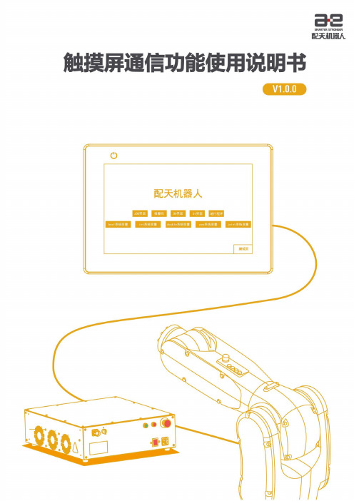
机器人触摸屏通信功能使用说明书
该设备类型与 4x 的设备类型属性是一样的。即发出读写的功能码完全一样。不同之处在于,当 为双字时,若 32_bit unsigned 格式的数据,使用 5x 和 4x 两种设备类型分别读取数据时,高字和 低字的位置是颠倒的。若使用 4x 设备类型读到的数据是 0x1234,那么使用 5x 设备类型读取的 数据即为 0x3412。
I
触摸屏通信功能使用说明书
前言
前言
关于本手册
本手册介绍了机器人触摸屏通信功能,并详细叙述了触摸屏通信功能的配置过 程。阅读本文档有助于读者掌握触摸屏通信功能的原理和各种配置信息。
操作前提
在操作机器人前,请务必仔细阅读产品的相关安全说明和操作说明,用户需在了 解安全知识和基础操作知识之后,才可使用机器人触摸屏通信功能。
修订记录累积了每次文档更新的说明。最新版本的文档包含以前所有文档版本的 更新内容。
表 2 本文中使用的标识
版本
发布时间
修改说明
V1.0.0
2022/01/28
第一次正式发布
文档编号及版本 文档相关信息见表 3。 表 3 文档相关信息 文档名称 文档编号 文档版本 软件版本
《触摸屏通信功能使用说明书使用说明书》 UM-S01500000033-002 V1.0.0 2.6.5
注意事项
◼ ARCS 软件版本需使用 2.6.5.220117_rc 及以上版本。 ◼ 若使用威纶通触摸屏,配套软件版本需使用 EBproV60602259_weinview 以上版本
连接方式
完成机器人和控制柜的连接后,使用网线将机器人控制柜的 Ethernet 网口和触摸屏网口连接即可。
Hi5 VR 手套 使用说明书
Noitom Hi5 VR手套用户使用说明书Ver. 1.5历史版本版本号版本日期版本说明1.0 2017.4 初版1.1 2017.09.12 1. 射频功能优化;2. 安装光学定位器优化;3. 穿脱方式优化;4. 校准动作及步骤优化。
1.2 2017.11.22 1. 多人同场射频功能优化;2. 震动交互说明变动;3. 续航时间优化。
1.3 2018.2.1 添加FCC声明1.4 2018.4.13 短按按键的功能变更1.5 2020.5.21 1.添加使用SteamVR软件说明2.添加校准的检查点目录1. 介绍 (1)2. 硬件部分 (2)2.1 组成 (2)2.2 交互 (3)2.3 功能特性 (4)2.4 射频(RF) (4)2.5 用法 (5)2.5.1 基本操作步骤 (5)2.5.2 手套配对 (6)2.5.3 消磁 (7)3. 结构部分 (9)3.1 安装光学追踪设备 (9)3.2 穿戴手套 (12)4. SDK (14)5. 校准说明 (15)5.1 注意 (15)5.2 校准步骤 (15)1. 介绍此文档为开发者提供了指导方案。
主要介绍了如何使用Noitom Hi5手套来对用户的手部动作进行动作捕捉和追踪。
注意事项:1. Noitom Hi5产品为成双售卖,但支持双手、单手使用两种使用模式。
2. Noitom Hi5手套需与光学追踪设备一起使用,以在追踪范围内获得用户小臂及手的绝对位置,并正确完成校准操作。
3. Noitom Hi5手套可兼容win7/8/10.4. 当前支持安装VIVE 追踪器及VIVE 手柄至Noitom Hi5手套上,作为光学追踪设备。
5. 当穿戴Noitom Hi5手套时,建议请勿手握VIVE 手柄或其他任何铁磁性物体,以免影响动作捕捉效果。
基本使用流程(供参考):安装VIVE 追踪器/手柄到Hi5手套上搭建好VIVE 环境VIVE 追踪器开机,匹配到Steam打开Hi5示例程序(Unity/Unreal) Hi5手套开机,会自动连接到收发器将Hi5 收发器插入头显或电脑穿戴Hi5手套戴上头显消磁校准(可跟随Hi5示例程序引导操作)2. 硬件部分2.1 组成Noitom Hi5产品包括1双Hi5手套(“手套”)及1个USB 2.0收发器(“Dongle”):( 图例 2.1-1 )( 图例2.1-2 )传感器安装平面 按键 指示灯USB 插头指示灯2.2 交互在每只手套和每个Dongle上,都有一个按钮和一个指示灯。
机械手说明书 (1)

2)本机械手的保养、维护、检修等工作,必须由受过专业培训的技术人员来承担;
3)无关人员进入机械手工作范围,应告知安全人员并了解应注意的安全要求;
4)没有征得制造商的同意,任何试图改变机械手原始设计的应用范围以及其它改装行为都是被禁止的;
二.安装与搬运
1.安装尺寸
2.包装尺寸
3.拆箱后搬运
注意!
搬运过程中禁止人员在机械手下方作业
注意!
假如机械手需要重新安装或者移动,请告知代理商或者制造商.
注意!
机械手在出厂前已确认完好状态,请在运输及拆箱过程中务必小心谨慎,
如果发现有因运输过失造成损伤,请立即告知运输公司,封存受损件以备检查,
并申请赔偿.
21
A00A090
耐磨垫
2
9
A00PSI12E
关节轴承
1
20
A00P81240
圆螺母
1
8
A00A080
定位柱
1
19
A00P85840
止退平垫
1
7
A00A070
旋出角度调整轴
1
18
A00P6008
滚珠轴承
2
6
A00A060
气缸旋转轴
1
17
A00PT81212
圆螺母
1
5
A00A050
拱旋转轴
1
16
A00PT85812
1
9
A00P15SL
手臂滑轨
1
18
A00PAS06
速度控制阀
2
8
A00C090
护管固定架
伟立机械手说明书(1)

进至 700
i、点击“吸夹动作”,选取 SV1 吸盘输出、SG1 夹具 1 输出,单击“插入”;
j、插入 Z1 上升至 0;
k、点击“轴动作”设置 X 横入至 0,继续单击“同动轴”,选取 Y1 后退至 0;
l、返回 是否退出教导界面 是
5.1.2 运行新建模组
退出教导后,按 STOP 键切换到主画面,过程如下:
003 前进,Y1:0.0 700.0 004 吸夹,吸 1 通,夹 1 通 005 后退,Y1:700.0 0.0
006 上升,Z1:400.0 0.0 007 横出,X:0.0 900.0 008 下降,Z1:0.0 400.0
009 前进,Y1:0.0 700.0 010 吸夹,吸 1 断,夹 1 断
5
a、当手臂要下降时,要特别注意手臂是在安全区域内。 b、操作前,请先确认人员是否在手臂行程范围外。 c、如不遵守此忠告,可能发生设备损坏或人员伤害
手动界面下包括轴、吸夹、备用。 X:主手臂、副手臂的横行坐标 Y1:主手臂的引拔坐标 Y2:副手臂的引拔坐标 Z1:主手臂下移坐标 Z2:副手臂下移坐标 C:侧姿的位置(水平/垂直)
4.2.5 修改 修改 在此可修改轴行程(每次最大调整距离为 1mm),轴运行等待的延 时,及运行速度。
进入主画面后点击 修改 ,进入修改界面,显示如下:
4.2.6 复位 复位 机械轴回归原点。
7
进入主画面后点击 复位 ,进行复位。
复位
是
4.2.7 试运行
试运行 测试当前模组是否符合模具要求(注:试运行模式不能替代全自 动运行)
全伺服系列
1
2
1、按键与开关的功能说明 1)紧急停止按钮
当有异常状况发生时,按下此钮,设备会立即停止运转并发出警报音,提醒 使用者设备异常。 2)使用/不使用开关 如若不使用机械手,请先确认机械手位置安全,可将此开关切换至关闭的位 置,此时手控器不可使用;需要使用时,可将此开关切换至开启的位置,手 控器可正常使用。 3)语言切换快捷键 一键切换提示语言。提示语言种类的选择也可在开机时进行。 4)自动运行 运行程序的开启键。在试运行/全自动中,当系统出现“请按左上角绿色 RUN
手套机人机界面说明书

一.织手套机人机界面简易示意框图设置界面进入键 开始键和停止键 复位键 速度界面进入键Enter 键和返回键设置数据用设置数据用二.各界面显示内容设定1.欢迎界面(编号1)显示内容如下: 欢迎界面手套各部位参数设置Run and Stop 复位界面 速度设置界面 长宽 密度 速度 游标左右移动键 游标上下增加键手套机设置显示系统1键 各部位设置 2键 速度设置 3键 运行 4键 停止(1)按1键各部位设置界面进入(2)按2键速度设置界面进入(3)按3键运行界面进入(4)按4键停止界面进入2.手套各部分参数主界面(编号2):1.大拇指2.食指3.中指4.无名指5.小拇指6.手掌7.手腕8.手肘(1)按enter键进入子界面(2)按return键返回上一层子界面(编号8):长宽密度速度00 00 00 00说明:子界面采用上下光标键进行数值设定,左右光标键进行切换(方向自左向右,自上向下)参数设置好按确认键进行数据发送。
3.复位界面设置(编号4)正在复位中...3.速度界面设置(编号5)设置速度:0 2 ↑↓说明:子界面采用上下光标键进行数值设定,左右光标键进行切换(方向自左向右,自上向下)参数设置好按确认键进行数据发送。
4.Run and Stop(编号6 编号7)正在运行中...当前速度:02 当前部位:手掌暂停中当前速度:02 当前部位:中指三.手套机按键说明1键各部位参数设置界面进入2键速度设置界面进入3键运行(进入run界面)4键停止(进入stop界面)5键enter键(进入下一层)6键return键(返回上一层)7键左光标键8键右光标键9键上光标键10键下光标键11键确认键(表示参数设置完成)。
Mechanix Wear 手套产品手册说明书

RECON TSRE-55
PURSUIT D5 TSCR-55
ELEMENT TSEL-55
0.5 mm M-PACT® MPSD-55
FASTFIT® F F TA B - 8 8
O R I G I N A L® MG-88
M-PACT® MP T- 8 8
M-PACT® 3 MP3-88
MULTICAM®
COVERT
Covert black hand protection is designed for law enforcement and special forces operating in mountainous or urban environments. Covert black is not a natural occurring color in nature, but it is an effective color that the brain perceives to provide depth. Mechanix Wear’s Covert black line of gloves provide depth as the eye interprets shadows and breaks up the user’s outline in the field.
S-L
MEN’S SIZES
S - XXL
COVERT
SPECIALTY VENT
Beat the heat wherever your mission takes you. Extremely hot or humid conditions can cause sweaty hands leading to the loss of valuable control in the field. Specialty Vent Covert shooting gloves provide evaporate cooling when the heat is on with a fully ventilated design. Breathable mesh combines with a perforated 0.6mm high-dexterity palm to allow cool air in and circulate throughout the glove. Specialty Vent shooting gloves feature perforated trigger fingers and dedicated flex joints to improve mobility.
开关机器人操纵手说明书

IL01222027EEffective Date 11/07Instruction Leaflet for Series G L - Frame Motor OperatorDO NOT ATTEMPT TO INSTALL OR PERFORM MAINTENANCE ON EQUIPMENT WHILE IT IS ENERGIZED. DEATH OR SEVERE PERSONAL INJURY CAN RESULT FROM CONTACT WITH ENERGIZED EQUIPMENT.ALWAYS VERIFY THAT NO VOLTAGE IS PRESENT BEFORE PROCEEDING.WARNINGRemove existing two screws from primary cover of breaker.Assemble support onto the breaker with four mounting screws supplied. Torque to 0.44 to 0.6 N.m or 4 to 5 in. lb.4•Turn breaker to the “OFF” position first.•Line up breaker handle and molded trigger of motor operator, and position motor operator on the breaker.Mount motor operator to breaker using mounting screws. Torque to 0.44 to 0.6 N.m or 4 to 5 in. lb.SupportMolded Trigger Mounting Screws (14 mm length)Breaker HandleMounting Screws(35 mm length) Mounting Screws(100 mm length)Manual OperationsMove the slide knob to the MANUAL position to expose the manual operating shaft located under the slide knob. The control power supply is cut off automatically.Insert the operating key into shaft slot. Turn the key clockwise to verify the breaker can be closed Leave breaker in the ON position. Press the manual PUSH-TO-TRIP button on the breaker to trip the breaker. Check that the display indicates the TRIP position.Turn the operating key clockwise (approximately 180°) again. This should reset the breaker. Turn the key (Clockwise only)Status IndicationPUSH-TO TRIP ButtonOpetating keyEffective Date 11/07Motor Operator Electrical DataVoltage Frequency Inrush Current 24VDC Application110-127VAC/110-125VDC Application48VDC Application9Lock-Off LeverLOCK-OFFMove slide knob to AUTO position. Pull outthe Lock-Off lever when breaker is in OFFposition, insert one to three padlock shacklesup to 6mm (.25 inch) in diameter.CAUTIONThe motor operator cannot be locked offwhile it is in the ON position.Printed in TQC。
InoTouch系列 触摸屏人机界面 说明书
■ IT5000安装尺寸图
单位:毫米
◆
◆ ◆
32bit RISC 400~800MHz 128MB 64MB DDRⅡ 256KB / / √ / / √ √ / √ √ √ √ √ √ √ / √ √ √ √
■ 安装注意事项
危险
☞ HMI需固定安装于平面,以下是安装时需注意的状况:
◆ ◆ ◆ ◆ ◆
正视图
侧视图
!
注意
HMI若安装于温度高于或低于手册建议储存温度范围可能会造成LCD液晶显示故障。
音频输出 视频输入 RTC
◆
危险
◆ ◆ ◆ ◆ ◆
!
电气规格
输入电压 额定电流 200mA 250mA 24VDC±20% 250mA 350mA 350mA
安装、配线等作业,请务必在切断全部电源后进行; 直流电源的配线,请按本说明书所述接于专用端子上; 在进行螺丝孔加工和接线时,不要使金属屑或电线头掉入HMI内部,以免发生火灾、故障、电子元件损坏; 避免带电状态进行接线、插拔电缆插头,否则容易导致电击,或导致电路损坏。 应仔细检查HMI的接线,确保工作电压和接线端子的位置均正确无误。如果电压或接线端子位置错误,可 能会引起火灾或事故。
☞ 按照NEMA 4标准安装步骤:
1) 2) 3) 4) 把产品放入面板上开好的安装孔中。 从面板背面将安装螺钉分别卡入产品外壳周围的4个安装螺钉固定孔。 逐个锁紧安装螺钉,直到产品牢靠地固定在面板上。不要过分用力锁紧安装螺钉。 为保证符合NEMA4的密封规范,所有的随产品提供的安装固定螺钉必须使用,并且安装面板的弯曲 度不能超过0.010”。
◆ ◆
一般规格
工作温度 工作湿度 存储温度 冷却方式 电磁兼容性 面板防护等级 安装方式 -5℃~55℃ 10%~90%RH(无冷凝) -20℃~70℃ 自然风冷 CE标准 IP65 按照NEMA 4标准或者VESA标准安装
KEBA机械手操作说明书(新版本)

操作说明机械手操作说明KEBA机械手0界面简介KeTop是KEBA公司专门为工业机械手手持终端提供的硬件解决方案,该手持终端运行KEBA公司自主研发的人机界面软件TeachView。
该人机界面具有易操作、人性化,符合人机工程学。
TeachView登录界面图左侧的灯与按钮分别为状态与配置管理部分,而右侧按钮为机械手动作操作按钮,底部的按钮则是调节部分。
除了上述三部分,还有急停按钮、USB接口、手动/自动开关。
左侧4个灯表示了系统运行状态。
系统正常启动为RUN灯亮,绿色。
发生错误Error灯会亮,红色。
机械手上电时Motion灯亮,绿色。
左侧7个图标,分别为自定义界面、配置管理、变量管理、项目管理、程序管理、坐标显示、信息报告管理。
右侧机械手动作操作部分,通过按“+”与“-”按键可以在编程或者点动时调节机械手的坐标位置,点击“2nd”按键可以翻到下一页(附加轴页)。
Start和Stop按钮与程序运行和停止有关。
底部F1、F2、Rob、F/B、Jog为闲置未定义按钮,Mot按钮用于机械手上电或下电,Step用于切换程序进入单步模式还是连续模式。
V+和V-用于调节机械手运动速度。
在主界面顶部,有一个状态栏,它包含了机械手的操作模式、状态、坐标、运动调节速度、程序名称、程序状态及执行模式、急停开关的状态、用户等级等有关机械手系统状态方面的信息。
1用户设置数据设置1.1数据设置在该界面用户可以设置机械手零点位置、零点允许误差以及最大位置。
零点允许误差主要用于零点的工作区域设置。
当用户设置的最大位置小于系统默认的最大位置时,该最大位置有效,否则系统使用默认最大位置。
操作数据1.2操作数据在该界面用户可以设置点动速度,回零点操作以及回参操作。
2配置管理维护2.1维护以下简要介绍一下维护界面底部的配置按钮:设置界面设置界面主要完成用户的登入、登出和系统设置。
登录界面可以选择要登录的用户,以及是否具有写权限和控制权。
机械手中文操作说明书

台灣三菱電機機器手臂中文操作說明書目錄1.操作面板功能…………………………………………………………..2.教導盒各鍵功能表………………………………………………………3.教導盒功能………………………………………………………………4.自動運轉操作4.1.動作速度設定………………………………………………………..4.2.程式號碼選擇………………………………………………………..4.3.程式運轉開始………………………………………………………..4.4.程式運轉停止………………………………………………………..4.5.程式運轉停止後再開始……………………………………………4.6.程式重新開始……………………………………………………….5.教導何功能解說5.1.程式編輯…………………………………………………………….5.2.運轉5.2.1.伺服驅動器………………………………………………….5.2.2.檢查………………………………………………………….5.3.程式管理5.3.1.程式一覽顯示……………………………………………….5.3.2.程式複製…………………………………………………….5.3.3.程式名稱更改……………………………………………….5.3.4.程式刪除…………………………………………………….5.4.監控5.4.1. 入力訊號……………………………………………………..5.4.2. 出力訊號……………………………………………………..5.4.3. 變數…………………………………………………………..5.4.4. 錯誤紀錄……………………………………………………..5.4.5. CC-LINK入出力資料5.5.維護5.5.1. 參數…………………………………………………………..5.5.2. 初始化………………………………………………………..5.5.3. 煞車釋放……………………………………………………..5.5.4. 原點設定……………………………………………………..5.5.5. 電源…………………………………………………………..5.6.設定5.6.1. 時間………………………………………………………….. 附錄(錯誤一覽表)…………………………………………………………..操作面板功能控制器操作面板的各部名稱1)開始鍵…………….執行程式使ROBOT動作。
浙江明德自动化设备 手套机电脑控制系统 说明书

手套机电脑控制系统说明书浙江明德自动化设备有限公司电话:0571-87995388操作说明一、功能简介本系统为手套机而设的电脑控制系统。
可带8个行程开关,16路电磁铁,全部由电脑控制。
本系统比较其它厂家控制系统有以下特点:1、液晶尺寸为192*64,具有背光,显示为中文和图标,直观明了。
2、编织过程中有工作进程指示灯指示当前工作位置,便于了解工作进度。
3、功能比较齐全:A、所有参数可密码保护,防止非法修改。
B、本机断电后可续织手套。
C、色纱分配可在本系统上设置修改。
D、电磁铁的工作速度可选择,使其能适合手套机的高速运行。
E、本机采用美国原装进口接插件,确保系统在恶劣环境下正常工作。
F、本系统采用变频器无级调速。
二、配置介绍本机有主机箱、按键板二部分组成。
虽然把主板和电源板装在一个箱体内,但是强电高压和弱电低压还是隔离,并且整体性能更好。
主机箱有以下接口。
(如上图)1、风扇接口2、按键板接线通道3、开关接口4、其它信号线通道按键板有以下接口(如下图)1、按键板接线通道2、手套进程指示灯3、液晶4、按键5、运行开关6、停止开关三、简要操作说明本机在开机后开始自检,如自检发现错误,则显示错误原因,可修改对应参数。
自检通过后,屏幕上显示本厂名,同时织手套进程指示灯循环闪动。
此时出现如下菜单:按任意键后进入主菜单。
1、开始手套编织2、设置工作参数3、测试工具箱4、设置系统参数5、显示版本信息6、中英文切换显示首次工作前,必须测试电磁铁,输入输出信号是否正常。
在正确设置系统参数和工作参数后,开始正常工作。
1、测试工具箱选择测试工具箱程序,确认后进入测试程序a.测试变频器b.测试输出信号c.测试行程开关d.测试信号板测试变频器按“上”、“下”键使设定转速加1、减1,按“右”、“左”键使设定转速加10、减10,设定转速最高为240转,最低为20转,设定转速的数值变化相应的变频器频率参数也变化,变频器频率参数最高为55.00,最低为5 左右。
tk6070ih使用说明

TK6070iH 系列触摸屏人机界面TK6070iH 安 装 说 明1.0 安装概述安装环境应用场所 TK6070iH 系列触摸屏人机界面是依据工厂应用环境而设计的工业产品。
它设计的规范可以保证它能够在0到50 °C (32到122 °F)的大多数工业环境中稳定工作。
它可能不能应用于某些特定的室外环境,如果您需要在室外的特定场合使用时,请务必向您的提供商咨询!防护规定 TK6070iH 系列触摸屏人机界面的前面板符合IP65的防护规定。
当产品正确地安装在符合IP65防护规定的盘柜上时,盘柜仍然保证符合IP65的规定,即当对盘柜表面喷淋液体时,液体不会渗入盘柜内部。
电气环境TK6070iH 系列触摸屏人机界面已经通过测试证明符合欧洲CE 电气认证的标准。
即产品的电路设计可以抵抗电气噪声的干扰,但这并不保证可以免除所有情况的电气噪声的干扰。
正确的布线和接地方式才能确保正确的使用。
机械环境为保证您正确的使用,请避免在存在强烈的机械振动的环境中安装TK6070iH 系列触摸屏人机界面产品。
2.0 安装说明2.1 安装指南2.1.1 安装位置请注意在产品背后安装设备时,请确保交流电源线、PLC 输出模块、接触器、启动器、继电器和其它类型的电气接口设备与TK6070iH 系列产品的背面距离较远。
特别需要注意与变频调速器和开关电源供应器保持较远的距离,这类设备的输入和输出电缆都必须采用屏蔽电缆,并将屏蔽网接到系统的星形接地点。
2.1.2 安装标准 盘柜 细节 TK6070iH 系列产品可以安装在深度超过105毫米的盘柜中,推荐您安装在盘柜的前面板上,为了保证不影响您正常地打开盘柜的前面板,请在安装产品的四周保持至少25毫米的空间距离。
为了保证您可以顺畅地连接电源和通讯电缆,我们建议您至少采用深度超过105毫米的盘柜。
安装把产品放入面板上开好的安装孔中,从面板背面将安装螺钉(包装盒内附)分别卡入产品外壳周围的4个安装螺钉固定孔,然后逐个锁紧安装螺钉,直到产品牢靠地固定在面板上。
新睿机械手说明书

前言非常感谢您购买xx机器人的机械手。
本机械手通过与注塑机的配合,以取出注塑机所加工的塑料产品,实现自动化生产作业。
此手册涉及机器的安全、安装、操作和维修保养等信息。
在操作之前请仔细阅读此说明书,相信如果能在熟读此操作说明书后进行正确操作,一定能够满足您的要求。
当您购买此机器后,请检查其型号、所有装箱单上所列零件,并检查运输过程中是否有任何部件受损。
如有任何部件遗漏或发现受损,请立即联系当地经销商或本公司。
我们再次感谢您的购买。
今后,本公司将继续努力进行技术开发、提高服务质量,制造出使您更满足的机械手。
免责事项●本手册的内容,将来可能更改,恕不预先通知。
●本手册内容的编写纰漏之处,在所难免,尚请不吝指正。
●本手册所载各种数据,系作本机的参考数据,并不负法律上的责任。
●由于顾客方面的改造、拆卸、误用、以及设备环境欠妥等本公司不能掌握的状况而造成损害时,本公司恕不负责。
目录五、控制器操作说明 (1)5.1手控器面板按键位置图 (1)5.2按键功能说明 (1)5.3操作说明 (2)5.3.1密码功能 (2)5.3.2中英文切换 (2)5.3.3手动操作说明 (3)5.3.4自动操作说明 (3)5.3.5错误报警 (4)5.3.6功能设置 (4)5.3.7教导说明 (7)5.3.8时间设置 (8)5.3.9 I/O监视说明 (8)5.4 标准动作程序 (9)5.5双臂动作程式 (11)六、故障说明 (13)6.1故障的编号及解释 (13)6.2故障说明及排除方法 (13)七、电气部分 (20)7.1电控系统安全规则 (20)7.2端口定义及接线说明 (21)7.2.1 36P线接线端口定义说明 (21)7.2.2中继板端口示意图 (22)7.2.3注塑机与机械手连接图 (23)7.2.4安装尺寸图 (24)7.2.5开关电源与中继板连接图 (25)五、控制器操作说明5.1手控器面板按键位置图5.2按键功能说明1数字键1/手臂上升/下降动作, 再按一次,则反相动作。
DOP-107H系列人机界面说明书
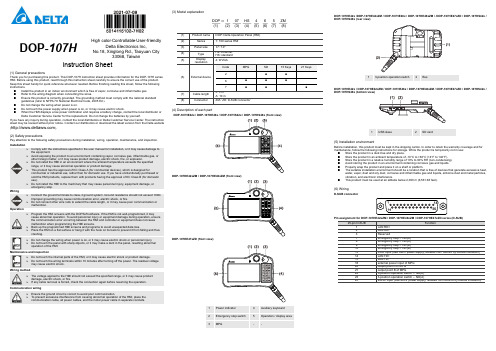
DOP-107HHigh color ‧Controllable ‧User-friendlyDelta Electronics Inc,No.18, Xinglong Rd., Taoyuan City33068, TaiwanInstruction Sheet(1) General precautionsThank you for purchasing this product. This DOP-107H instruction sheet provides information for the DOP-107H series HMI. Before using this product, read through this instruction sheet carefully to ensure the correct use of the product. Keep this sheet handy for quick reference whenever needed. Before finishing reading this sheet, follow the following instructions. ⏹ Install the product in an indoor environment which is free of vapor, corrosive and inflammable gas. ⏹ Refer to the wiring diagram when connecting the wires. ⏹ Ensure this product is correctly grounded. The grounding method must comply with the national standardguidelines (refer to NFPA 70: National Electrical Code, 2005 Ed.). ⏹ Do not change the wiring when power is on. ⏹ Do not touch the power supply when power is on, or it may cause electric shock. ⏹ When the HMI displays a low power notification and requires a battery change, contact the local distributor orDelta Customer Service Center for the replacement. Do not change the batteries by yourself.If you have any inquiry during operation, contact the local distributors or Delta Customer Service Center. The instruction sheet may be revised without prior notice. Contact our distributors or download the latest version from the Delta website ( ).(2) Safety precautionsPay attention to the following safety precautions during installation, wiring, operation, maintenance, and inspection.Do not change the wiring when power is on, or it may cause electric shock or personnel injury. Do not touch the panel with sharp objects, or it may make a dent in the panel, resulting abnormaloperation of the HMI.Maintenance and inspectionDo not touch the internal parts of the HMI, or it may cause electric shock or product damage.Do not touch the wiring terminals within 10 minutes after turning off the power. The residual voltagemay cause electric shock.(3) Model explanation(1) DOP(2) 1(3) 07(4) HS(5) 4(6) 6(7) 5(8)ZM(4) Description of each partDOP-107HE42x / DOP-107HE46x / DOP-107HS42x / DOP-107HS46x (front view)DOP-107HE42xZM / DOP-107HE46xZM (front view)DOP-107HE47xZD (front view)DOP-107HE42x /DOP-107HE42xZM / DOP-107HE46x / DOP-107HE46xZM / /DOP-107HE47xZD / DOP-107HS42x / DOP-107HS46x (rear view)DOP-107HE42x / DOP-107HE42xZM / DOP-107HE46x / DOP-107HE46xZM / DOP-107HE47xZD / DOP-107HS42x / DOP-107HS46x (bottom view)(5) Installation environmentBefore installation, this product must be kept in the shipping carton. In order to retain the warranty coverage and for maintenance, follow the following instructions for storage. While the product is temporarily not in use: ⏹ Store the product in a dust-free and dry place. ⏹ Store the product in an ambient temperature of -10°C to +60°C (14°F to 140°F). ⏹ Store the product in a relative humidity range of 10% to 90% RH (non-condensing). ⏹ Avoid storing the product in an environment containing corrosive gas and liquids. ⏹ Properly wrap the product and place it on a shelf or platform. ⏹ The suitable installation environment should be a location that is free of devices that generate excessive heat,water, vapor, dust and oily dust, corrosive and inflammable gas and liquids, airborne dust and metal particles, vibration, and electronic interference. ⏹ This product must be used at an altitude below 2,000 m (6,561.68 feet).(6) WiringD-SUB connectorPin assignment for DOP-107HE42xZM / DOP-107HE46xZM / DOP-107HE47xZD series (D-SUB)Wiring of DOP-107HS42x / DOP-107HS46xCable definition for DOP-107HS42x / DOP-107HS46x seriesWiring of DOP-107HE46xCable definition for DOP-107HE46x series(8) Output description of MPGElectrical specificationsConfigurationNote:1. If connecting more than one devices for MPG control is required, connect them according to the electricalspecifications for MPG output to avoid malfunction.2. DC 5V and DC 24V devices that receiving pulses are supported. Ensure the device complies with the requiredvoltage, or it may cause damage to the equipment.Note:1. The half-life of the backlight is defined as the maximum luminance being reduced by 50% when the maximum drivecurrent is supplied to the HMI. The life of LED backlight shown here is estimated at the room temperature of 25°C (77°F) with ambient humidity.2. The withstand voltage of the isolated power circuit is 1500V peak for 1 minute.3. The certification for some models is under application. Contact the local distributor for the certificated models.4. The HMI power consumption is the power consumed when the HMI is not connecting with other peripheral devices.To ensure normal operation of the HMI, the recommended capacity of the power supply is 1.5 to 2 times of the specified power consumption.5. Isolated power supply unit is suggested.6. You can download the DOP-107H series programming software DOPSoft, user manual, and HMI installation sheetfrom Delta’s website. The instruction sheet may be revised without prior notice. Download the latest version from the Delta website ().7. The DOP-107H series products can be used with industrial automation equipment. Read though this instructionsheet carefully and install the product according to the instructions to avoid danger.8. Cleaning method: use a dry cloth to clean the product.9. For repair and maintenance, contact Delta Electronics, Inc. Address: No. 18, Xinglong Rd., Taoyuan City, Taiwan.TEL: +886-3-3626301.DOP-107H Yüksek Renk ‧ Geniş Ekran ‧ KullanıcıDostuDelta Electronics Inc,No.18, Xinglong Rd., Taoyuan City33068, TaiwanBilgi Dokümanı(1) ÖnsözBu ürünü satın aldığınız için teşekkür ederiz. Bu bilgi dokümanı DOP-107H serileri için bilgiler sağlar. Ürünü kullanmadan önce, doğru şekilde kullanım sağlamak için lütfen dokümanı tamamen okuyunuz. Ayrıca daha sonra ihtiyaçduyulduğunda kullanabilmek için bu dokümanı iyi muhafaza ediniz. Bu dokümanı okumayı bitirdikten sonra lütfenaşağıda yazılı olan talimatları uygulayınız.⏹Ürünün kurulumunu aşındırıcı, yanıcı gaz veya sıvılardan uzak, temiz ve kuru yerlere yapınız. Sadece içmekânda kullanınız.⏹Tüm bağlantıların dokümanda belirtildiği gibi olduğuna emin olunuz.⏹HMI toprak bağlantısının doğru olduğuna emin olunuz. Topraklama metodu uluslararası elektrik standardınauyumlu olmalıdır (NFPA 70: National Electrical Code, 2005 Ed).⏹Ürün enerjili iken operatör panelini sökmeyiniz ve bağlantılara müdahale etmeyiniz.⏹Çalışma sırasında güç kaynağına dokunmayınız. Aksi halde elektrik çarpması meydana gelebilir.⏹HMI düşük pil uyarısı gösterirse ve pil değişimi gerekirse lütfen firmamız ile temasa geçiniz, kendinizdeğiştirmeyiniz.Ürünün kullanımı ile ilgili sorularınız için teknik servisimizle iletişim kurabil irsiniz. Bu bilgi dokümanının içeriği herhangi bir bildirime gerek duyulmadan değiştirilebilir. Dokümanın son versiyonunu internetten indirebilirsiniz.()(2) Güvenlik ÖnlemleriKurulum, kablolama, çalıştırma, bakım ve inceleme esnasında aşağıdaki güvenlik önlemlerine dikkat ediniz.KurulumKurulumu yaparken kullanım kılavuzunda belirtilen talimatlara uyun, aksi halde ekipmana ve kendinize zarar verebilirsiniz.Ürünü buhar, aşındırıcı gaz, yanıcı gaz veya diğer yabancı maddeler içer en bir ortama maruz bırakmaktan kaçının aksi halde ürünün zarar görmesine, elektrik çarpmasına, yangına veyapatlamaya neden olabilir.Operatör panelini belirtilen çalışma sıcaklığı aralığında olmayan bir ortama monte etmeyin, aksi halde anormal çalışmasına veya zarar görmesine neden olabilir.Bu ürün evde kullanım yerine ticari veya endüstriyel kullanım için tasarlanmış olan KC Class A onayına sahiptir. Bu ürünü ev kullanımı için bilmeden satın aldıysanız veya sattıysanız KC Class Bsertifikası olan ürün ile değiştirin.Personel yaralanmasına, ekipman arızasına veya acil durdurmaya neden olabilecek makinalara bu ürünü kurmayın.KablolamaToprak terminalini Class 3 toprak sistemine bağlayın. Toprak direnci100Ωgeçmemelidir. Yanlış topraklama iletişim hatasına, elektrik çarpmasına veya yangına neden olabilir.Kablo boyunu uzatmak için ek kablo bağlamayın. Zayıf haberleşmeye veya arızaya neden olabilir.ÇalıştırmaOperatör panelini DOPSoft yazılımıyla programlayın. Eğer operatör paneli iyi programlanmamış ise anormal çalışmasına neden olabilir. Çalışırken personelin yaralanmasını veya ekipmanların zarargörmesini önlemek için, operatör paneli ile kontrolör arasında meydana gelebilecek iletişim hatasınınolmadığından operatör paneli programlar iken emin olun.Program veya veri kaybını önlemek için operatör panelinin programının yedeğinin alındığından emin olunuz.Operatör panelini düz bir yüzeye yerleştirin veya düşerek çarpmasını önlemek için kancaya sırtının üzerine asın.Cihaz enerjili iken kablol arı değiştirmeyiniz. Bu elektrik çarpmasına veya personel yaralanmasına neden olabilir.Operatör paneli ekranına keskin objeler ile dokunmayınız aksi takdirde operatör panelinin anormal şekilde çalışmasına neden olabilir.Bakım ve İncelemeOperatör pane linin iç donanım veya parçalarına kesinlikle dokunmayın, aksi takdirde elektrik çarpmasına veya ürünün hasar görmesine sebep olabilir.Cihazın enerjisi kesildikten sonra 10 dk. b oyunca cihaza dokunmayın. Artık voltaj elektrik çarpmasına neden olabilir.Kablolama MetoduOperatör paneline bu dokümanda belirtilen voltaj aralığı dışında voltaj uygulanmamalıdır, aksi takdirde üründe hasara, elektrik çarpmasına veya yangına neden olabilir.Herhangi bir kablonun çıkarılmasında zorlanılırsa, işleme devam etmeden önce bağlantıyı tekrar kontrol edin.Haberleşme KablolamaHaberleşmede sorun olmaması için toprak devresinin doğru olduğundan emin olun.Operatör panelinin anormal çalışmasına neden olabilecek elektronik parazit oluşmasını engellemek için tüm güç kablo larının ve motor kablolarının ayrı kanala yerleştiğinden emin olun.(3) Ürün Açıklaması(1)DOP(2)1(3)07(4)HS(5)4(6)6(7)5(8)ZM(1) Ürün AdıDOP: Delta Operatör Paneli (HMI)(2) Serisi 1: 100 serisi Operatör Paneli(3)PanelBoyutu07: 7.0"(4) TipiHE: EthernetHS: Standart(5)EkranÇözünürlüğü4: WVGA(6) Harici GirişKod MPG (El Çarkı)SD 15 Tuş21 Tuş2 ●●6 ●●●7 ●●●(7)KabloUzunluğu5: 5 mA: 10 m(8) Konnektör ZM: D-SUB konnektör(4) Parça AçıklamalarıDOP-107HE42x / DOP-107HE46x / DOP-107HS42x / DOP-107HS46x (Ön Görünüm)DOP-107HE42xZM / DOP-107HE46xZM (Ön Görünüm)DOP-107HE47xZD (Ön Görünüm)1 Enerji Göstergesi 4 Yardımcı Klavye2 Acil Stop Butonu 5 Dokunmatik Ekran / Display3 MPG (El Çarkı)- -DOP-107HE42x / DOP-107HE46x / DOP-107HS42x / DOP-107HS46x / DOP-107HE42xZM / DOP-107HE46xZM //DOP-107HE47xZD (Arka Görünüm)1 3-pozisyonlu operasyon butonu2 BusDOP-107HE46x / DOP-107HS46x / DOP-107HE42x / DOP-107HS42x / DOP-107HE46xZM / DOP-107HE42xZM /DOP-107HE47xZD (Alt Görünüm)1 USB slave2 SD Kart(5) Kurulum OrtamıKuruluma kadar bu ürün nakliye kutusunda saklanmalıdır. Garanti kapsamını korumak ve bakım için ürün geçicikullanımda değil iken aşağıdaki saklama talimatlarını takip ediniz:⏹Ürünü tozsuz ve kuru bir yerde saklayın.⏹Ürünü -10°C ~ +60°C (14°F ~ 140°F) arasındaki bir ortam sıcaklığında saklayınız.⏹Ürünü 10% ila 90% RH (yoğuşmasız) arasındaki bir ortam sıcaklığında saklayınız.⏹Ürünü aşındırıcı gaz ve sıvı içeren bir ortamda saklamaktan kaçının.⏹Ürünü uygun bir şekilde sarın ve rafa veya platforma yerleştirin.⏹Uygun kurulum ortamı, aşırı ısı, su buharı, toz ve yağlıaşındırıcı toz, yanıcı gaz, havada taşınabilecek metalparçası, titreşim ve elektronik parazit olmayan, arındırılmış bir yer olmalıdır.⏹Bu ürün 2,000 m (6,561.68 feet) altındaki bir rakımda kullanılmalıdır.(6) KablolamaD-SUB KonnektörDOP-107HE42xZM / DOP-107HE46xZM / DOP-107HE47xZD Serisi (D-SUB) Pin Açıklaması25-pin D-SUB Açıklama1 LAN RD+2 LAN RD-3 Rezerve7 Acil Stop –NO(A)8 Acil Stop –NO(A)9 Acil Stop –NC(B)10 Acil Stop –NC(B)13 0V (SELV devresi tarafından beslenir. (MAINS’den çift yalıtımlı izole))14 LAN TD+15 LAN TD-18 MPG (El Çarkı) besleme 5V/24V DC20 A fazı, MPG21 B fazı, MPG22 3-pozisyonlu operasyon butonu–NO(A)23 3-pozisyonlu operasyon butonu–NO(A)25 24V DC (SELV devresi tarafından beslenir. (MAINS’den çift yalıtımlı izole))DOP-107HS42x / DOP-107HS46x için KablolamaDOP-107HS42x / DOP-107HS46x Serisi için Kablo RenkleriDOP-107HE46x KablolamaDOP-107HE46x Serisi için Kablo Renkleri(8) MPG (El Çarkı) Açıklamaları Elektriksel ÖzelliklerKonfigürasyonNot:a. MPG kontrolü için birden fazla cihaz bağlanması gerekirse, arızaları önl emek için bunları MPG çıkışı için verilenelektrik özelliklerine göre bağlayın.b. Darbe alan 5V ve 24V DC cihazları desteklenir. Cihazın istenen gerilime uyduğundan emin olun, aksi haldeekipmana zarar verebilir.Notlar:1. Arka ışık yarı-ömrü maksimum besleme akımı operatör paneline uyg ulandığında orijinal parlaklığın %50 oranındaazaltılmış olması olarak tanımlanır. Burada gösterilen LED aydınlatma ömrü 25⁰C (77°F) normal sıcaklık ve nemkoşullarında tahmini bir değerdir.2. İzoleli güç devresi dayanma voltajı 1 dakika için 1500 V pik.3. Bazı modeller için sertifika başvuru aşamasındadır. Sertifikalı modeller için Delta Türkiye ile iletişime geçin.4. Operatör paneli güç tüketimi herhangi bir cihaza bağlı değil iken tükettiği güçtür. Normal çalışma için tavsiye edilengüç kaynağı tüketilen gücün1.5 ~ 2 katıdır.5. İzoleli güç kaynağı kullanılması tavsiye edilir.6. DOP-107H serisi ürünlerin program editörü olan DOPSo ft programı ve kullanıcı manueli web sayfamızdanindirilebilirsiniz. .7. DOP-107H serisi endüstriyel otomasyon don anımı olarak kullanılabilir. Tehlikeleri önlemek için bu bilgi dokümanınıdikkatlice okuyun ve belirtilen direktiflere göre kurulumu gerçekleştirin.8. Temizleme yöntemi: Ürünü temizlemek için kuru bir bez kullanın.DOP-107H 高彩‧可控制‧友善人機介面Delta Electronics Inc,No.18, Xinglong Rd., Taoyuan City33068, Taiwan安裝說明(1) 一般注意事項感謝您使用本產品,本人機介面安裝說明書提供DOP-107H系列人機介面的相關資訊。
(4.5)人机界面操作使用说明
人机界面操作使用说明山东鲁能积成电子股份有限公司2002年8月目录1.运行人机界面 (1)1.1.人机界面启动 (1)1.2.人员登记 (1)1.3.退出人机界面模块 (2)2.控制台窗口 (3)2.1.控制台窗口总览 (3)2.1.1.基础样式 (3)2.1.2.命令行样式 (3)2.2.命令行操作 (5)2.3.控制台工具栏 (6)2.3.1.系统设置与维护菜单总揽 (7)2.3.2.系统功能设置 (8)2.3.3.人员设置菜单 (14)2.3.4.口令设置菜单 (15)2.3.5.报警设置菜单 (15)3.索引图介绍 (17)3.1.索引图总揽 (17)3.2.定制索引图 (17)4.系统图形的调出 (19)4.1.调出总索引图 (19)4.2.其它任意图形的调出 (19)4.3.循环调图操作 (20)5.系统菜单命令 (21)5.1.图形漫游、浏览、打印等基本操作 (21)5.2.查询统计态操作 (23)5.3.设备信息浏览 (26)5.4.设备定位 (27)5.5.事故追忆 (28)5.6.故障模拟操作 (28)6.命令操作 (31)6.1. 遥测操作 (31)6.2. 对位操作 (33)6.3. 设备操作 (34)6.3.1.开关、刀闸操作 (34)6.3.2.变压器操作 (43)6.3.3.馈线操作 (44)7.曲线图操作 (44)8.事项窗浏览 (46)9.地理信息图操作说明 (47)9.1.进入地理信息图 (47)9.2.地理信息图的地图操作 (47)9.2.1.地理图操作主菜单 (47)9.2.2.主菜单操作项介绍 (48)9.3.地理信息图的实时信息及操作 (56)9.4.地理图文件的复制及实时数据初始化 (58)1.运行人机界面1.1.人机界面启动在人机界面没有启动的情况下,点击桌面iESDMS文件夹中的DMSMMI快捷方式或者在C:\IESDMS\BIN\目录下的DMSMMI.EXE文件名上双击就可以进入配网人机界面操作环境。
- 1、下载文档前请自行甄别文档内容的完整性,平台不提供额外的编辑、内容补充、找答案等附加服务。
- 2、"仅部分预览"的文档,不可在线预览部分如存在完整性等问题,可反馈申请退款(可完整预览的文档不适用该条件!)。
- 3、如文档侵犯您的权益,请联系客服反馈,我们会尽快为您处理(人工客服工作时间:9:00-18:30)。
一.织手套机人机界面简易示意框图
二.各界面显示内容设定
1.欢迎界面(编号1)
显示内容如下:
(1)按1键各部位设置界面进入
(2)按2键速度设置界面进入
(3)按3键运行界面进入
(4)按4键停止界面进入
2.手套各部分参数
主界面(编号2):
(1)按enter键进入子界面
(2)按return键返回上一层
子界面(编号8):
说明:子界面采用上下光标键进行数值设定,左右光标键进行切换(方向自左向右,自上向下)参数设置好按确认键进行数据发送。
3.复位界面设置(编号4)
3.速度界面设置(编号5)
说明:子界面采用上下光标键进行数值设定,左右光标键进行切换(方向自左向右,自上向下)参数设置好按确认键进行数据发送。
4.Run and Stop(编号6 编号7)
三.手套机按键说明。