说明书-霍尼韦尔-HRMS 2112D 无线开关
Honeywell HD1系列微型开关产品说明说明书
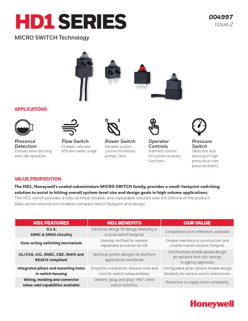
HD1 SERIESMICRO SWITCH Technology004997Issue 2VALUE PROPOSITIONThe HD1, Honeywell’s sealed subminiature MICRO SWITCH family, provides a small-footprint switching solution to assist in hitting overall system-level size and design goals in high volume applications.The HD1 switch provides a fully certified, reliable, and repeatable solution over the lifetime of the product.Slow-action mechanism enables compact switch footprint and design.APPLICATIONSPresenceDetectionEnsures door latchingand safe operationFlow SwitchEnables safe andefficient water usagePower SwitchReliable systemcontrol for motors,pumps, fansOperatorControlsInterface controlfor system auxiliaryfunctionsPressureSwitchDetection andwarning of highpressure or overpressure eventsUnless otherwise stated, all characteristic measurements tested according to UL, EN and IEC standards and conditions. Parameters and acceptance criteria validated and confirmed in a certified lab environment. Technical details available upon request.2 Sensing and Internet of Things 3FIGURE 1. PRODUCT NOMENCLATUREHD1Switch TypeElectrical Rating10HD1 SeriesSealedSwitchTerminationCircuit Code1Mounting1Wire SizeA01Actuator TypeA**** Standard wire length is 150 mm [5.91 in] long. Other lengths available upon requestMax. Operating Force @ PlungerSWire Type****M—Special DesignatorMA special designator code is used to indicate some non-standard feature such as a special actuator,wire color, connector, etc.Review product specification to determine the nature of the non-standard feature. This code will consist of up to three alphanumeric characters. A blank designates no difference from the standard listing.4 Datum reference is pillarsACTUATORDatum reference is base of switch for pcb terminalsDatum referenceis top of switch if no pillar or no pcb terminalsNote: “Honeywell” name will be tool marked and rating symbols will be laser marked.FIGURE 2. HD1 SERIES DIMENSIONSPACKAGE DIMENSIONS PILLAR DIMENSIONSZD HDApplications that requireflexibility in design with special configurations available Cost-sensitive applications requiring configurability in actuation and termination Applications that require slow-action mechanism and small overall design footprintLogic level and power-duty (3 A, 125 Vac) amp ratings Industry standard switch footprint and global certifications ideal for “low-cost-of-failure” applications Smallest sealed switch footprint in the Honeywell MICRO SWITCH WARRANTY/REMEDYHoneywell warrants goods of its manufacture as being free of defective materials and faulty workmanship during the applicablewarranty period. Honeywell’s standard product warranty applies unless agreed to otherwise by Honeywell in writing; please refer to your order acknowledgment or consult your local sales office for specific warranty details. If warranted goods are returned to Honeywell during the period of coverage, Honeywell will repair or replace, at its option, without charge those items that Honeywell, in its sole discretion, finds defective. The foregoing is buyer’s sole remedy and is in lieu of all other warranties, expressed or implied, including those of merchantability and fitness for a particular purpose. In no event shall Honeywell be liable for consequential, special, or indirect damages.While Honeywell may provide application assistance personally, through our literature and the Honeywell web site, it is buyer’s sole responsibility to determine the suitability of the product in the application.Specifications may change without notice. The information we supply is believed to be accurate and reliable as of this writing.However, Honeywell assumes no responsibility for its use.004997-2-EN | 2 | 02/21© 2021 Honeywell International Inc. All rights reserved.m WARNINGIMPROPER INSTALLATION• Consult with local safety agenciesand their requirements whendesigning a machine-control link, interface and all control elements that affect safety.• Strictly adhere to all installationinstructions. Failure to comply with theseinstructions could result in death or serious injury.m WARNINGMISUSE OFDOCUMENTATION•The information presented in this product sheet is for reference only. Do not use this document as a product installation guide.•Complete installation, operation, and maintenance information is provided in the instructions supplied with each product.Failure to comply with theseinstructions could result in death or serious injury.HoneywellSensing and Internet of Things 830 East Arapaho Road Richardson, TX FOR MORE INFORMATIONHoneywell Sensing and Internet of Things services its customers through a worldwide network of sales offices and distributors. For application assistance, current specifications, pricing, or the nearest Authorized Distributor, visit or call:USA/Canada +302 613 4491Latin America +1 305 805 8188Europe +44 1344 238258Japan +81 (0) 3-6730-7152Singapore +65 6355 2828Greater China+86 4006396841RELATED DOCUMENTATION• Submin Comparison Chart • Applying Precision Switches • ZD datasheet • ZW datasheet。
Honeywell IH21 UHF RFID Reader 配件指南说明书

IH21 HANDHELD UHF RFID READER Accessories GuideACCESSORIESIH21-EPL-CT40IH21-EPL-CT50ePop-Loq Snap-On Adaptor for CT40Snaps easily on or off the mobile computer. Compatiblewith the homebase for terminal charging.ePop-Loq Snap-On Adaptor for CT60Snaps easily on or off the mobile computer. Compatiblewith the homebase for terminal charging.IH21 RFID READERSIH21A0002IH21A0014IH21 Bluetooth®RFID ReaderWith ePop-Loq®, UHFAntenna, Trigger Handle,Battery, Battery Cover, noimager, red and black. ETSIIH21 BluetoothRFID ReaderWith ePop-Loq, UHFAntenna, Trigger Handle,Battery, Battery Cover, noimager, red and black. FCCIH21-EPL-EDA50IH21-EPL-D75EePop-Loq Snap-On Adaptor for ScanPal™ EDA50Snaps easily on or off the mobile computer. Compatiblewith the homebase for terminal charging.ePop-Loq Snap-On Adaptor for D75eSnaps easily on or off the mobile computer. Compatiblewith the homebase for terminal charging.IH21 Handheld UHF RFID Reader Accessories Guide | 2ScanPal is a trademark or registered trademark of Honeywell International Inc. Bluetooth is a trademark or registered trademark of Bluetooth SG, Inc.ePop-Loq is a trademark or registered trademark of Technology Solutions (UK) Ltd.All other trademarks are the property of their respective owners.IH21 Handheld UHF RFID Reader Accessories Guide | Rev B | 06/19© 2019 Honeywell International Inc.For more informationHoneywell Safety and Productivity Solutions 9680 Old Bailes RoadFort Mill, SC 29707800-582-4263 IH21-CB-1IH21-QBC-1318-060-001IH21 Docking Homebase Kit includes power supply unit and mini USB lead. 4-Slot Battery Charger Must order 12V 4A power supply and power cord separately. Individual charge status LED for each battery slot in addition to a main power supply status LED.Spare Battery For IH21 RFID reader, 3.7V 2300 mAh.。
Honeywell 一线 wireless 传感器产品介绍说明书

Remote Analytical MeasurementsHoneywell OneWireless wireless transmitters enable automated monitoring of variables in areas where traditional hard-wired transmitters are too costly, difficult or time-consuming to implement. Whether applications are remote, without access to power, difficult to reach, or in hazardous areas, Honeywell’s wireless solutions deliver needed information easily, flexibly, and affordably.Regulatory fines or citations may result from unmonitoreddischarge of storage locations such as lagoons, ponds,holding tanks, pits stream discharge or leaks aroundchemical plants or refineries. Remote analyticalmeasurements are often necessary but not implemented dueto the high cost. Wiring a transmitter to a monitoring stationcan cost $20-$80 per foot.Until now, remote measurement of pH, ORP, dissolvedoxygen and conductivity has not been available for theseapplications.Honeywell’s XYR™ 5000 wireless transmitter combined withHoneywell’s DirectLine transmitter and a commerciallyavailable solar power system are the obvious and economical solution to this problem.This self-contained and self-powered solution utilizes proven Honeywell technology and a commercially available solar power system to monitor up to two measurements remotely and economically.The Honeywell wireless transmitter is powered by long life, self contained battery and requires no licensing or special set up. The DirectLine module is powered by the solar system and has a battery back-up for extended periods of low sun or dark. The wireless transmitter and the DirectLine transmitter are simple to set-up, requiring only hours to complete an installation. Whereas a wired solution requires a significant investment in time and money to run the signal and power back to the monitoring station.The Honeywell XYR 5000/DirectLine wireless solution eliminates physical and economical barriers to remote monitoring of analytical measurements. This solution excels in limited or no power remote locations, where manual or no readings are made today, allowing plants to:•Reduce opportunity for regulatory fines•Reduce installation, maintenance and operating costs •Improve plant safety by monitoring remote sitesRemote Analytical Measurements2More InformationFor more information on Honeywell’s OneWireless solutions, visit our website /ps/wireless , or contact your Honeywell account manager.Automation & Control Solutions Process Solutions Honeywell2500 W. Union Hills Dr. Phoenix, AZ 85027Tel: +1-602-313-6665 or 877-466-3993 /psHoneywell Remote Analytical Measurements (a) Honeywell Wireless Analog Signal Transmitter (b) Honeywell Wireless Transmitter Base Radio Honeywell Smart Sensors(c) Honeywell DirectLine Modules and SensorsSO-08-03-ENG February 2008© 2008 Honeywell International Inc.Notes: 1) Solar power supply to be purchased from SEPCO (); 772.220.6615. 2)All DirectLine models can be use with these solutions.。
霍尼韦尔说明书

霍尼韦尔说明书霍尼韦尔说明书简介霍尼韦尔(Honeywell)是一家全球领先的多元化科技和制造公司,总部位于美国,成立于1906年。
公司的业务涵盖航空航天、楼宇技术、性能材料、可持续性解决方案和安全解决方案等领域。
霍尼韦尔以其创新的技术、高品质的产品和可靠的性能享誉全球。
本文档旨在向用户提供关于霍尼韦尔产品的说明,并介绍如何正确使用和维护这些产品。
产品列表1. 霍尼韦尔智能温控器* 产品名称:霍尼韦尔智能温控器* 产品型号:TH9320WF5003* 产品特点:- 可与智能手机和智能家居系统连接,实现远程控制- 可编程设置温度和计划,提高能源效率- 大屏幕显示温度和湿度等信息* 使用说明:1. 将温控器与电源连接,并按照说明书设置温度和计划。
2. 下载并安装霍尼韦尔智能手机应用。
3. 打开应用,按照提示添加温控器设备。
4. 连接温控器和手机,即可实现远程控制。
2. 霍尼韦尔空气净化器* 产品名称:霍尼韦尔空气净化器* 产品型号:HFD-120-Q* 产品特点:- 高效过滤空气中的颗粒物和有害物质- 自动检测空气质量,并自动调整清洁模式- 低噪音设计,不影响正常生活* 使用说明:1. 将空气净化器放置在需要净化的房间内,并连接电源。
2. 按下电源开关,启动空气净化器。
3. 空气净化器将自动检测空气质量,并根据需要调整清洁模式。
4. 定期更换空气净化器中的滤网,以确保最佳的净化效果。
常见问题与解答Q1:为什么温控器无法连接智能手机?A:请确保智能手机和温控器处于相同的Wi-Fi网络下,并且已经下载并安装了霍尼韦尔智能手机应用。
如果问题仍然存在,请尝试重新连接温控器。
Q2:空气净化器何时需要更换滤网?A:根据使用环境和空气质量,滤网的寿命可能会有所不同。
一般建议每3至6个月更换一次滤网,或者根据空气净化器上的指示灯提示更换。
维护与保养为了保证霍尼韦尔产品的正常运行和延长使用寿命,以下是一些维护与保养的建议:1. 定期检查产品的电源和连接线,确保其无损坏和松动。
霍尼韦尔自控面板操作说明举例
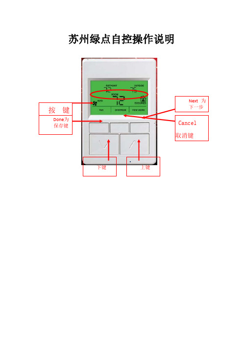
苏州绿点自控操作说明•面板对照表第一种类型UI1 MAU-201出风温度UI2 MAU-202出风温度UI5 MAU-201风车压差AO1 MAU-201冰水阀开度AO2 MAU-202冰水阀开度DI3 MAU-202风车压差Wsp_t1 MAU-201出风温度设定Wsp_t2 MAU-202出风温度设定Qh 冬夏切换第二种类型UI2 AHU-201回风温度UI3 2F末端水管压力AO1 AHU-201冰水阀开度AO2 AHU-201新风风门DI3 AHU-201风车压差DI4 AHU-201滤网压差Wsp_t1 AHU-201回风温度设定Qh 冬夏切换TR71面板操作说明面板显示点与接线表相对应例如:UI1:出风温度DI3:风车压差AO1:冰水阀开度AO1_DIS:冰水阀开度显示AO1_AM:与上述对应的手自动切换,“0”为自动,“1”为手动AO1_IN:与上述对应手动强制输入点Wsp_t1:出风温度设定值,可任意修改所需值以下为面板操作步骤:上述为主界面,按右边第一位,就可以进入显示屏上分3段,刚好底下有3个按键与此对应,从左到右依次为DONE,CANCEL,NEXT(确定,取消,下一步)按住NEXT,就可以看到这台控制器里面所有的点上述为UI1,继续点击NEXT,就能看到所有UI点对应的数据。
上述为DI1,显示风车的状态,故障和压差等,显示数值为“0”和“1”,“0”代表运行和正常,“1”代表停止与故障。
上述为阀体的开度显示点,AO1_DIS为蒸汽阀的开度显示上述为AO1冰水阀的手自动切换点,“0”代表蒸汽阀受程序自动控制,按照设计好的程序进行;“1”代表蒸汽阀不受程序控制,根据手动输入的值进行。
即“1”代表手动,“0”代表自动。
按面板上的上下键,就能修改数值。
上述为当AO1为手动强制输入之后的,AO1的强制输出值,通过上下键修改数值,之后按左上角的DONE键确认。
(0~100对应0~10V)上述为水泵和阀体的启停点,“0”代表停止,“1”代表启动。
蜂鸟电子有限公司 Honeywell 无线磁感应门闸联系人产品说明书
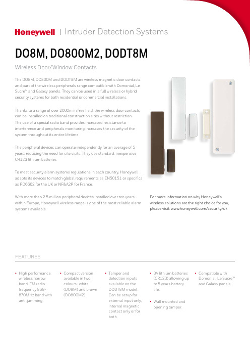
The DO8M, DO800M and DODT8M are wireless magnetic door contacts and part of the wireless peripherals range compatible with Domonial, Le Sucre™ and Galaxy panels. They can be used in a full wireless or hybrid security systems for both residential or commercial installations.Thanks to a range of over 2000m in free field, the wireless door contacts can be installed on traditional construction sites without restriction. The use of a special radio band provides increased resistance to interference and peripherals monitoring increases the security of the system throughout its entire lifetime.The peripheral devices can operate independently for an average of 5 years, reducing the need for site visits. They use standard, inexpensive CR123 lithium batteriesTo meet security alarm systems regulations in each country, Honeywell adapts its devices to match global requirements as EN50151 or specifics as PD6662 for the UK or NF&A2P for France.With more than 2.5 million peripheral devices installed over ten years within Europe, Honeywell wireless range is one of the most reliable alarm systems available.DO8M, DO800M2, DODT8MWireless Door/Window Contacts• High performance wireless narrow band, FM radio frequency 868-870MHz band with anti-jamming.• Compact version available in two colours : white(DO8M) and brown (DO800M2).• Tamper anddetection inputs available on the DODT8M model. Can be setup for external input only, internal magnetic contact only or for both.• 3V lithium batteries (CR123) allowing up to 5 years battery life. • Wall mounted and opening tamper.• Compatible withDomonial, Le Sucre™ and Galaxy panels.FEATURESFor more information on why Honeywell’s wireless solutions are the right choice for you, please visit: /security/ukIntruder Detection SystemsHSFI-DO-01-EN(0516)DS-Z May 2016© 2016 Honeywell International Inc.For more information/security/uk Fax: +44 (0) 1698 738300email:***************************Honeywell Security and FireNewhouse Industrial Estate Motherwell, Lanarkshire ML1 5SB, Scotland Tel:+44 (0) 1698 738200DO8M, DO800M2, DODT8MWireless Door/Window ContactsDODT8MAlarm input mode: • External • Internal• Both。
Honeywell HRMS-2112D 智能无线控制器 说明书
Honeywell
© 2010 Honeywell International Inc.
进入编程模式后指示灯状态恢复:“关闭”“打开”或“打开”“关闭”
-9-
Honeywell
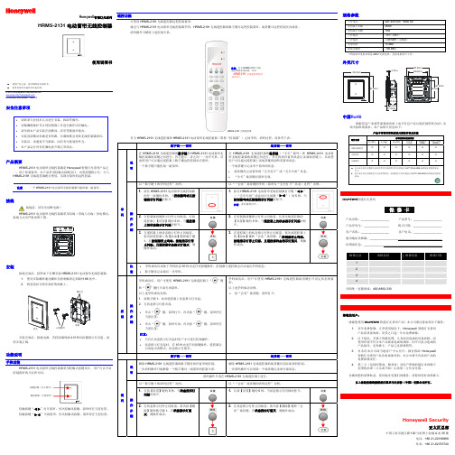
3. 当控制器处于编程模式时,长 按无线遥控器的【设置】键约 5 秒,当遥控器上的状态指示灯 闪烁时松开。 此时遥控器进入编程模式。 4. 在面板按键指示灯和状态指示 灯停止闪烁前,依次按遥控器 上的【添加】键和【会客】 键,若
1. 使用 HRMS-2112D 智能无线控制器或 HRMS-2191 无线遥控器对 应数字键打开(或关闭)要添加到“会客”场景键的那路灯光。 2. 长按控制器上对应按键约 5 秒,当控制器鸣响且按键指示 灯闪烁时松开。 此时控制器进入编程模式。
注意:
按下按键时指示灯状态改变: “打开”“关闭”或“关闭”“打开”
ห้องสมุดไป่ตู้
控制器停止鸣叫、按键指 示灯停止闪烁,且 遥控器状态指示灯熄灭。
则操作成功。 此路灯光被成功添加至“会客”场景键,且为打开(或关闭)状态。
- 10 -
Honeywell
删除场景灯光 删除场景,即解除遥控器上场景键对实际场景的控制。 以下步骤以删除上述“会客”场景为例对删除场景灯光操作进 行说明。
尊敬的用户: 感谢您使用Honeywell智能灯光系列产品!本公司谨向您承 诺以下服务: 1. 壹年免费保修:正常使用情况下,Honeywell 智 能灯光系列产品因质量故障,第一年(以霍尼 韦尔发票之日起 12 个月)免费维修。 2. 以下情况,不属于保修范围:人为原因造成的 设备故障、因使用环境不符合本产品要求造成 的故障、因不可抗力造成的产品损坏、无保修 卡、产品已过保修期等。 3. 对未经本公司或当地客户中心允许、擅自拆卸 Honeywell 智能灯光系列产品各组成部件的, 本公司将不再承担产品的免费保修责任。 4. 第三方(包括经销商、服务商)对用户所做的 超出本保修卡范围的承诺(口头或书面)由该 第三方负责兑现。 为确保您的消费权益,更好地享受我们的服务,请您保管好此 保修卡。
霍尼韦尔_电动阀门使用说明书

100
0
0
100
141 233
322 (
接线图
尺寸 Fig. 2. ML7420A (mm)
ML7420A (0/2...10 V)
位置反馈
Y
2…10V 0(2)…10V
M
24V 24V~ 1
24V
超越开关
24V~
!
2
附件
12 3456
S1
S2
辅助开关 250 Vac / 5(3) A
4
执行器不会再自动进行自适应模式。
ECC-CDA-VA05-MAR-2011-V01-CN
2
模1信 当)。拟对号输应当入L输对E信应D入灯号LE暗YD可时灯通,亮过输时位入,于型输P号入C为型B2右号..侧.为10按0.V.钮.d1cW0。V2进dc行(出选厂择设(见置图); 注节意。: 按钮W3和W2以及电位计W1可在移开上盖后进行调
技术参数
产品概述
出M暖L2通7..4空.120调0AV系系d统c列的。电位动置阀反门馈执信行号器. 它可们为可阀广门泛提应供用调于节加型热控,制通并风且及输
温度
工作环境温度 贮工存作环介境质温温度度
信号
输入信号 位置反馈信号
安全
电气保护等级 防防护火等等级级
材料
上盖 基座 支架
℃( -10~+50 5~95% RH)
使用说明
器内达M概L与置到7述4阀的特2门弹定0系阀簧的列杆组阀执件杆,行使推实器执力现由行时阀同器门,步的的内电输上部机出下开驱力运关动限动关,制闭。通在。过出一厂个设卡置子范连围接内执。行当 非按针手手 以弹下旋动手动簧旋转旋动复钮钮开,操位并自关执作执顺动执行行时解行器器针锁器连旋接(。。M转件只L7向,有42上执在0运行关A)动器闭带连电。有接源如手件后果动向才执旋下可行钮运以器,动进返在行回;失手自反电动动之情操控,况作制逆下则时。可 所时超 制有,。越的执执行选行器项器会都运带行有到超全越开功或能全关(见的接位线置图,)。不当再超受越输功入能信作号用的控
Honeywell 限位和封闭式开关 说明书

电路电气额定值单刀双掷A UL/CSA额定值:15A,125,250或480 VAC;2A,600 VAC;1/8HP,125 VAC;1/4 HP,250 VAC;1/2A,125 VDC;1/4 A,250 VDC。
双刀双掷B UL/CSA额定值;10A,125或250 VAC;0.3A,125 VDC;0.15 A,250 VDC。
小型封闭式开关E6/V6系列E6(侧装)和V6(法兰安装)开关可带或不带致动器密封罩。
两者均有胶粘于底壳内的复合绝缘体/密封件。
用铅制垫圈密封侧装开关上的安装孔。
所有侧装开关均用6号螺钉安装,BZE6-2RN7除外(它用8号螺钉)。
卸去底壳就会露出端子,这样方便于接线。
特点侧装或法兰安装瞬时或保持接触接地螺钉可提供(22 A)高容量温度范围在-25°F到+160°F(-32°C至+71°C)铸锌外壳NEMAIUL认可,文件号为E12252CSA认证,文件号为LR41372E6 NEMA1V6 NEMA 1.3环氧树脂填充,符合NEMA1,3,4,12,13保持等级有预置引线或连接器端接的选项直柱塞致动开关侧装,有密封罩侧装,无密封罩滚轮柱塞致动开关侧装,有密封罩电气额定值订货指南说明电气额定值安装目录号O.P.mmin.O.F.Noz.最大P.T.mmin.最小O.T.mmin.最大D.T.mmin.侧装BZE6-2RN 43,66±0,761.719±.030带有密封罩单刀双掷A法兰安装BZV6-2RN 69,09±1,522.720±.0602,50-6,679-241,98.0785,56.2190,05.002除8号安装螺钉外,与BZE6-2RN同A 侧装BZE6-2RN7 43,66±0,761.719±.0302,50-6,679-241,98.0785,56.2190,05.002侧装DTE6-2RN 46±0,761.812±.080带有密封罩双刀大掷B法兰安装STV6-2RN 71,4±0,762.812±.0307,23-16,426-592,80.1103,17.1251,53.060侧装BZE6-2RQ 38,1±0,761.500±.030不带有密封罩单刀双掷A法兰安装BZV6-2RQ 63,5±1,142.500±.0452,50-3,629-130,38.0155,56.2190,05.002订货指南说明电气额定值安装目录号O.P.mmin.O.F.Noz.最大P.T.mmin.最小O.T.mmin.最大D.T.mmin.侧装BZE6-2RN80带有密封罩,滚轮平行于开关长轴,单刀双掷A法兰安装BZV6-2RN8056,7±1,142.232±.04582,1±1,143.232±.0452,50-6,689-241,98.0785,55.2190,05.002带有密封罩,滚轮平行于开关长轴,双刀双掷B 侧装DTE6-2RN80 59,6±1,02.345±.0405,56-13,820-482,80.1103,17.1251,53.060侧装BZE6-2RQ8 49,6±1,141.953±.045不带密封罩,滚轮平行于开关长轴,单刀双掷A法兰安装BZV6-2RQ8 75±1,522.953±.0602,50-3,629-130,38.0155,55.1400,05.002N=牛顿特性:O.F.-动作力; P.T.-预行程; O.T.-超行程;D.T.-差动行程; O.P.-操作位置小型封闭式开关E6/V6系列交 叉滚轮柱塞执行开关法兰安装 无密封罩滚轮杠杆执行开关法兰安装 有密封罩侧装无密封罩订货指南说 明电气 额定值安 装目录号O.P.mm in. O.F. N oz.P.T. mm in.O.T. mm in.最大 D.T.mm in.侧装 BZE6-2RQ81 49,6±1,14 1.953±.045 A 法兰安装BZV6-2RQ81 75±1,52 2.953±.060 2,50- 3,62 0,38 .015 3,55 .140 0,05 .002侧装BZE6-2RN8156,7±1,14 2.232±.045 同上,有封罩 A 法兰安装 BZV6-2RN8182,1±1,14 3.232±0.452,5- 6,67 1,98 .078 5,56 .219 0,05.002无密封罩,滚轮 垂直于开关的 长轴单刀双掷9-139-24订货指南说 明电气 额定值安 装 目录号 O.F. N oz. 最大 P.T. mm in. 最小 O.T. mm in. 最大 D.T. mm in. 侧装BZE6-2RN2 单刀双掷 A 法兰安装BZV6-2RN2侧装DTE6-2RN2双刀双掷 B 法兰安装DTV6-2RN2 2,78- 8,35 10-30 6,76 .266 5,56 .219 4,19 .165 侧装 BZE6-2RQ2 单刀双掷 A 法兰安装BZV6-2RQ2 2,78- 5,01 10-184,78 .1885,56 .2190,15 .006无密封罩,同 上调节,除水 平可以45°增 量调节外双刀双掷 B 侧装DTE6-2RQ22,78- 5,57 10-206,76 .2665,56 .2194,19 .165有密封罩,现 场可作水平方 向360°调节, 垂直方向180° 调节2,78- 4,78 5 ,56 0,055,57 .188 .219 .006 10-20单向滚轮杠杆执行开关侧装 有密封罩力较小的控制杆杠杆使用时控制杆或与开关成一行或者切断。
Honeywell MICRO SWITCH HS Series 蜂巢封闭大型基本开关数据表说明书
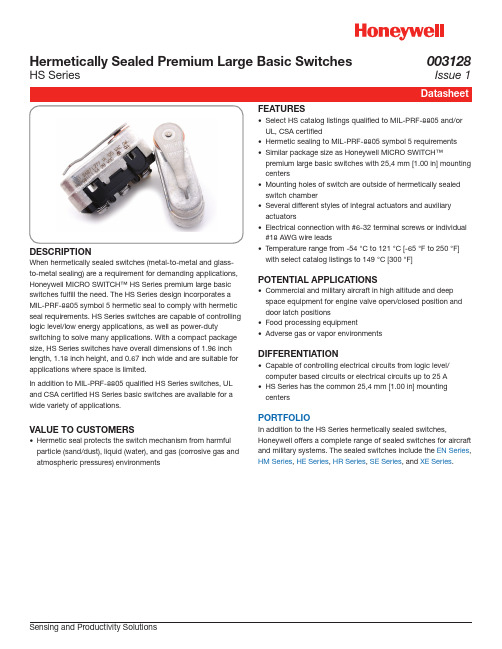
Hermetically Sealed Premium Large Basic SwitchesHS SeriesDESCRIPTIONWhen hermetically sealed switches (metal-to-metal and glass-to-metal sealing) are a requirement for demanding applications, Honeywell MICRO SWITCH™ HS Series premium large basic switches fulfill the need. The HS Series design incorporates a MIL-PRF-8805 symbol 5 hermetic seal to comply with hermetic seal requirements. HS Series switches are capable of controlling logic level/low energy applications, as well as power-dutyswitching to solve many applications. With a compact package size, HS Series switches have overall dimensions of 1.96 inch length, 1.18 inch height, and 0.67 inch wide and are suitable for applications where space is limited.In addition to MIL-PRF-8805 qualified HS Series switches, UL and CSA certified HS Series basic switches are available for a wide variety of applications.VALUE TO CUSTOMERS• Hermetic seal protects the switch mechanism from harmful particle (sand/dust), liquid (water), and gas (corrosive gas and atmospheric pressures) environmentsFEATURES• Select HS catalog listings qualified to MIL-PRF-8805 and/or UL, CSA certified• Hermetic sealing to MIL-PRF-8805 symbol 5 requirements • Similar package size as Honeywell MICRO SWITCH™premium large basic switches with 25,4 mm [1.00 in] mounting centers• Mounting holes of switch are outside of hermetically sealed switch chamber• Several different styles of integral actuators and auxiliary actuators• Electrical connection with #6-32 terminal screws or individual #18 AWG wire leads• Temperature range from -54 °C to 121 °C [-65 °F to 250 °F] with select catalog listings to 149 °C [300 °F]POTENTIAL APPLICATIONS• Commercial and military aircraft in high altitude and deep space equipment for engine valve open/closed position and door latch positions• Food processing equipment• Adverse gas or vapor environmentsDIFFERENTIATION• Capable of controlling electrical circuits from logic level/computer based circuits or electrical circuits up to 25 A • HS Series has the common 25,4 mm [1.00 in] mounting centersPORTFOLIOIn addition to the HS Series hermetically sealed switches,Honeywell offers a complete range of sealed switches for aircraft and military systems. The sealed switches include the EN Series , HM Series , HE Series , HR Series , SE Series , and XE Series .Sensing and Productivity Solutions003128Issue 12 HS SERIES SWITCHESThe HS Series hermetically sealed basic switches are designed for side mounting on 25,4 mm [1.00 in] centers. The mounting of the switch is outside the hermetically sealed switch chamber. The external material for the HS Series is stainless steel and thermoset plastic.Electrical terminations for the HS Series switches are individual wire leads or integral #6-32 terminal screws. CIRCUITRY1PDTELECTROMECHANICAL SWITCHES Array Definitions below explain the meaning ofoperating characteristics. Characteristicsshown in tables were chosen as mostsignificant. They are taken at normal roomtemperature and humidity. These may varyas temperature and humidity conditionsdiffer. Sketches show how characteristicsare measured for in-line plunger actuation.Linear dimensions for in-line actuation arefrom top of plunger to a reference line.Differential Travel (D.T.) – Plunger oractuator travel from point where contacts‘‘snap-over’’ to point where they ‘‘snapback.’’Free Position (F.P.) – Position of switchplunger or actuator when no external forceis applied (other than gravity).Full Overtravel Force – Force required toattain full overtravel of actuator.Operating Position (O.P.) – Position ofswitch plunger or actuator at which pointcontacts snap from normal to operatedposition. Note that in the case of flexible oradjustable actuators, the operating positionis measured from the end of the lever orits maximum length. Location of operatingposition measurement shown on mountingdimension drawings.Operating Force (O.F.) – Amount of forceapplied to switch plunger or actuator tocause contact ‘‘snap-over.’’ Note in thecase of adjustable actuators, the forceis measured from the maximum lengthposition of the lever.Overtravel (O.T.) – Plunger or actuatortravel available beyond operating position.Pretravel (P.T.) – Distance or angletraveled in moving plunger or actuator fromfree position to operating position.Release Force (R.F.) – Amount of forcestill applied to switch plunger or actuatorat moment contacts snap from operatedposition to unoperated position.Total Travel (T.T.) – Distance from actuatorfree position to overtravel limit position.Sensing and Productivity Solutions 34 PRODUCT DIMENSIONS Figure 1. 1HS1 mm [in]Figure 2. 1HS3 mm [in]1 Mounting holes will accept pins or screws of Ø 3,53 [0.139] max. diaNOTEØ 9,8 [0.19] x 4,8 [0.19] Wide1 Mounting holes will accept pins or screws of Ø 3,53 [0.139] max. diaNOTESensing and Productivity Solutions 5Figure 3. 1HS41 mm [in]Figure 4. 4HS4-118 mm [in]1 Mounting holes will accept pins or screws of Ø 3,53 [0.139] max diaNOTE1 Mounting holes will accept pins or screws of Ø 3,53 [0.139] max diaNOTEFigure 5. ADH3721R2 Lever mm [in]NOTES1 Screws, nuts, and lockwashers furnished unassembledWarranty/RemedyHoneywell warrants goods of its manufacture as being free of defective materials and faulty workmanship. Honeywell’sstandard product warranty applies unless agreed to otherwise by Honeywell in writing; please refer to your order acknowledgement or consult your local sales office for specific warranty details. If warranted goods are returned to Honeywell during the period of coverage, Honeywell will repair or replace, at its option, without charge those items it finds defective. The foregoing is buyer’s sole remedy and is in lieu of all other warranties, expressed or implied, including those of merchantability and fitness for a particular purpose. In no event shall Honeywell be liable for consequential, special, or indirect damages.While Honeywell may provide application assistance personally, through our literature and the Honeywell web site, it is up to the customer to determine the suitability of the product in the application.Specifications may change without notice. The information we supply is believed to be accurate and reliable as of this printing. However, we assume no responsibility for its use.003128-1-EN IL50 GLO July 2016© 2016 Honeywell International Inc. All rights reserved.m WARNINGPERSONAL INJURYDO NOT USE these products as safety or emergency stop devices or in any other application where failure of the product could result in personal injury.Failure to comply with these instructions could result in death or serious injury.m WARNINGMISUSE OF DOCUMENTATION•The information presented in this product sheet is for reference only. Do not use this document as a product installation guide.•Complete installation, operation, and maintenanceinformation is provided in the instructions supplied with each product.Failure to comply with these instructions could result in death or serious injury.Find out moreHoneywell serves its customers through a worldwide network of sales offices, representatives and distributors. For application assistance, current specifica-tions, pricing or name of the nearest Authorized Distributor, contact your local sales office. To learn more about Honeywell’s sensing and control products, call +1-815-235-6847 or 1-800-537-6945,visit , or e-mail inquiries to *********************ADDITIONAL MATERIALSThe following associated literature is available on the Honeywell web site at :• Product installation instructions • Aerospace range guideHoneywell Sensing and Productivity Solutions 9680 Old Bailes Road Fort Mill, SC 29707 。
Honeywell 传感器和开关应用说明书

Sensors and Switches for Valves and Flow Meters An Application NoteBackgroundFlow meters can measure and regulate volumetric flow, velocity from which the volumetric flow is determined, and mass flow. Valves control or regulate the flow of gases or fluids by partially obstructing, opening or closing the pipeline that carries the media. In many applications, they are operated manually by a lever, pedal, or wheel. Valves are often used in oil and gas, chemical manufacturing, water reticulation and mining applications. Automatic valves with diaphragms or pistons are often actuated by changes in pressure, temperature or flow.SolutionsHoneywell manufactures a wide range of sensors and switches, from simple on/off switches to electronic sensors designed to deliver system control, fluid level indication, temperature regulation, along with protection from overheating and starting/stopping the compressor. Honeywell components provide enhanced reliability, minimize down time, and improve robustness in most harsh environments.Various package options are available, including stainless steel, and those designed for hazardous and harsh-duty applications.Hazardous-location limit switches – These specialized switches perform a number of functions, including monitoring the position ofthe valve stem, actuator or wheel position, providing on-off position on manual process valves, providing real-time valve status information for improved productivity and safety. As these limit switches are enclosedin an explosion-proof housing, any flame path is extinguished inside which mitigates the risk of causing an explosion at the switch part.These switch components provide feedback for the user to take actionin order to prevent explosions in hazardous environments. Hazardous-location switches are employed in valves in outdoor, above-ground, potentially explosive environments such as oil and gas or water treatment applications.Limit Switches – Employed to monitor the position of the valve stemor actuator, limit switches are primarily used on valves in non-explosive environments such as waste water treatment plants, power generation plant or other factory applications. They also allows users to remotely monitor the valve stem, actuator lever, or wheel position for improved productivity and reduced total installed cost in hazardous locations.Figure 1. Industrial Valve ApplicationValves serve a variety of purposes in industrial applications, although their main purpose is to control media through a system.Wireless Limit Switches – Allows users to remotely monitor valve stem, actuator lever, or wheel position for improved productivity and safety, while reducing total installed cost with an economical wireless point-to-point solution.Basic Switches –Snap-action switches monitor the position of the valve handle by indicatingif the switch is actuated. These switches are employed on valves used in both non-explosive environments such as waste water treatment plants and/or other factory applications and also explosive/hazardous applications. Invalve monitoring applications, basic switches perform position sensing on cams with no power consumption. In addition to valves, Honeywell’s V15W2 Series is suitable for use in hazardous environments such as refrigeration, HVAC,appliances, and paint booths.Hall-effect Speed Sensors and Sensor ICs – In flow meter applications Honeywell’s speed sensors measure flow by monitoring revolutions of the impeller (an inside propeller). Eachrevolution of the impeller equates to the delivery of a certain amount of fluid. For example, if the user sets a fluid level of five gallons per minute,the speed sensor counts the impeller rotation so that the correct amount of fluid is delivered. Invalve monitoring application, Hall-effect sensor ICS measure position sensing on cams.Position Sensors – In flow meter applications, Hall-effect magnetic position sensors are usedto determine valve position. In valve monitors, position sensors deliver continuous position status with enhanced reliability and accuracy.Pressure Transducers and Switches – In valve actuator applications, pressure transducers and switches measure the pressure of the diaphragm to help regulate and control the flow within the pipeline. The sensors can measure differential pressure by comparing values across the valve. They can also give an indication of valve position related to opening and closing by measuring the pressure value at that time.Snap-Action SwitchPosition SensorSMART Position SensorHall-Effect Position Sensor ICwith Actuatorsin hazardous locationsLimit SwitchLearn more aboutthe XYR6000OneWireless™ SensorClick here to view Hazardous Area Limit SwitchesRead more about MICRO SWITCH Limit Switches12Explosion-Proof Valve Position IndicatorMICRO SWITCH VPX • Valve position indicator in explosion-proof housing2334Basic SwitchMICRO SWITCH BZ, V7, V15, V15W2, and ZW Series • Large, miniature, and subminiature basic switchesHazardous Location Limit SwitchMICRO SWITCH LSX, CX, and BX Series • Premium limit switches in explosion-proof housingLimit SwitchMICRO SWITCH HDLS, GL, and Double Break Series • Premium heavy duty and standard global limit switches14Figure 4. Switches in Valve Actuators and PositionersClick here to view VPX Series Valve Position IndicatorsGet details on the SMART PositionSensor familyFigure 5. Sensing and Switching Products Used in Valve ActuatorsHazardous Location Position Sensor XYR6000 OneWireless™ SeriesAllows users to remotely monitor valve stem, actuator lever, or wheel position for improved productivity and safety, while reducing total installed cost in hazardous locations; part of a scalable ISA100 mesh networkHazardous Area Limit SwitchMICRO SWITCH™ LSX/CX/BX/EX SeriesMonitors valve stem, actuator lever, or wheel position, providing real-time position status for improved productivity and safety in hazardous locationsLimit SwitchMICRO SWITCH™ HDLS, GLS, and Double Break SeriesMonitors valve stem, actuator lever, or wheel position, providing real-time position status for improved productivity and safetyPosition SensorSMART Position Sensor, SPS Series 75 mm Linear Monitors valve stem or actuator position1234Stainless Steel Media Isolated Pressure Sensor or Pressure Switch MLH, PX2, or PX3 Series Pressure Sensor or HP, HE, ME, LP, or LE Series Pressure SwitchMeasures diaphragm pressure6Valve Actuator(Kammer valve actuator photoused with permission of Flowserve.)Wireless Limit SwitchMICRO SWITCH™ HDLS and GLS SeriesAllows users to remotely monitor valve stem, actuator lever, or wheel position for improved productivity and safety, while reducing total installed cost with an economical wireless point-to-point solution5Learn more about MICRO SWITCH Basic SwitchesReview Limitless™ Wireless SwitchesFind out more on Hall-effect Speed SensorsFigure 6. Sensing and Switching Products Used in Valves and Flow MetersSMART Position Sensor SPS Series75mm analog and 225 mm analog and digital linear configuration Position Sensor SR SeriesDigital position sensorHall-Effect Sensor LCZ or 3000 SeriesSingle, zero speed sensor (LCZ) or high resolution VRS sensor (3000)Basic SwitchMICRO SWITCH BZ, V7, V15, V15W2, and ZW SeriesLarge, miniature, and subminiature basic switchesHazardous Location Limit Switch MICRO SWITCH VPX, CX, LSX, and BX SeriesPremium limit switches in explosion-proof housingLimit SwitchMICRO SWITCH HDLS, GLS,and Double Break SeriesPremium heavy duty and standard global limit switchesFlow MeterClick here to view Pressure TransducersMore information available here on Hall-effect Sensor ICsTypes of ValvesSpecifically, there are several main types of valves: 1) Manual process valves, 2) Valve actuators/positioners, 3) Valve monitors/indicators, 4) Valves and flowmeters, and 5) Sanitary and food/beverage valves.Manual Process Valves – Manual process valves in industrial facilities control the flow of liquid, gas, slurry, or steam. Eighty percent require operators to manually open, close, or otherwise control the valve. At any given time, users may not know the actual position of the valve. Process plants, including refineries, chemical, pharmaceutical, and water treatment plants as well as power generation installations, all need a better way to verify status with or without human intervention, especially in hazardous or hard-to-reach locations. (See Figures 2 and 3)Valve Actuators/Positioners – A valve actuator is a pneumatic or electric mechanism used in process control systems to automatically open or close valves. Actuators can be used with either linear or rotary valves in industrial, medical, food/beverage, and transportation applications. In standard valves, when the valveis given a command to open to a certain point, there is no feedback to verify that it has opened to that position. Valve positioners utilize a source of power to operate and continuously adjust a valve. The power source can be a manual gearbox or an electronic device with control and measuring devices; Available with hydraulic, pneumatic, and electric operating mechanics, these are often used in pipelines, process plants and in remote areas. Postioners can be used for opening or closing a valve to control the rate of fluid flow based on a signal from a central control system. With a valve positioner, the command is given and the valve positioner reads the opening, verifies position, and readjusts (if necessary) to the exact position needed which allows for excellent precision in the valve setting. (See Figures 4 and 5)Valve Monitors/Indicators – Mechanical or electrical valve monitors and indicators are used in process control to show valve position. They provide an electrical signal, and sometimes visual feedback, to accurately monitor and verify that a valve is in the correct position. Valve monitors are mostly used in conjunction with a valve positioner/actuator to provide information from remote locations that are not easilyaccessed, or where power isn’t readily available. Potential applications include chemical, pharmaceutical, power generation and oil and gas processes. (See Figures 4 and 5)Valves and Flowmeters – Valves control or regulate the flow of gasses or fluids by partially obstructing, opening or closing the pipeline that carries the media. Valves are often usedin oil and gas, chemical manufacturing, water reticulation and mining applications. In many of these applications, the valves are operated manually by a lever, pedal or wheel. Automatic valves with diaphragms or pistons are often actuated by changes in pressure, temperature or flow.Flow meters can measure and regulate volumetric flow, velocity from which the volumetric flow is determined, and mass flow. The turbine flow meter translates the mechanical action of the turbine rotating in the liquid flow around an axis into a user-readable rate of flow (gpm, lpm, etc.). The turbine wheel is set in the path of a fluid stream. The flowing fluid impinges on the turbine blades, imparting a force to the blade surface and setting the rotor in motion. Nearly all flow meters mustbe installed so that there is a significant runof straight pipe before and after the locationof the flow meter. This is intended to allow the straight pipe run to “smooth out” any turbulence produced by the presence of valves, chemical injectors and diffusers, and changes in pipe direction. (See Figure 5)Sanitary and Food/Beverage Valves – Sanitary and food and beverage valves are engineered for pressure control in sanitary (or “clean”) environments. They are usually manufactured with stainless steel for sanitary and high-purity applications. These valves are often constructed as a ball valve around a fullbore design that ensures the product passes through the valve with no restrictions on the flow with minimal pressure drop.Sanitary and food and beverage valves are often found in pharmaceutical, biotechnology, food and beverage, cosmetics, chemical and other industries where sanitary process control is required for steam, gases, and liquids such as water-for-injection systems.000697-7-EN | 7 | 04/21© 2021 Honeywell International Inc.Honeywell Advanced Sensing Technologies830 East Arapaho Road Richardson, TX 75081 /astFor more informationHoneywell Advanced Sensing Technol-ogies services its customers through a worldwide network of sales offices and distributors. For application assistance, current specifications, pricing or the nearest Authorized Distributor, visit /ast or call:Asia Pacific +65 6355-2828Europe +44 (0) 1698 481481USA/Canada+1-800-537-6945Warranty/RemedyHoneywell warrants goods of its manufacture as being free of defective materials and faulty workmanship during the applicable warranty period. Honeywell’s standard product warranty applies unless agreed to otherwise by Honeywell in writing; please refer to your order acknowledgment orconsult your local sales office for specific warranty details. If warranted goods are returned to Honeywell during the peri-od of coverage, Honeywell will repair or replace, at its option, without charge those items that Honeywell, in its sole dis-cretion, finds defective. The foregoing is buyer’s sole rem-edy and is in lieu of all other warranties, expressed or implied, including those of merchantability and fitness for a particular purpose. In no event shall Honeywell be liable for consequential, special, or indirect damages.While Honeywell may provide application assistance per-sonally, through our literature and the Honeywell web site, it is buyer’s sole responsibility to determine the suitability of the product in the application.Specifications may change without notice. The information we supply is believed to be accurate and reliable as of this writing. However, Honeywell assumes no responsibility for its use.m WARNINGPERSONAL INJURYDO NOT USE these products as safety or emergency stop devices or in any other application where failure of the product could result in personal injury.Failure to comply with these instructions could result in death or serious injury.m WARNINGMISUSE OF DOCUMENTATION• The information presented in this product sheet is for reference only. Do not use this document as a product installation guide.•Complete installation, operation, and maintenance information is provided in the instructions supplied with each product.Failure to comply with these instructions could result in death or serious injury.。
Honeywell TP系列手动开关 说明书

高出面板 齐平面板电气额定值(A)28 VDC115 VDC 250 VDC 115 V AC 60和400 Hz 230 V AC 电气额定值 代码电感 电阻 电灯电阻电阻电感电阻电灯电阻1 15 20 5 0.75 0.5 10 15 3 52 10 15 4 0.75 0.5 7 15 2 63 15 20 7 0.75 0.5 15 154 6 4 10 185 0.75 0.5 8 11 26 5 12 20 5 0.75 0.5 15 15 4 6 6 10 18 4 0.75 0.5 8 11 26特 点 • 两位和三位按钮动作 • 各种按钮颜色• 单极双极和四极电路布置 • 高出面板和齐平面板的安装 •温度范围自-65°F 至+160°F (-54°C 至+71°C) • UL CSA 认证结 构高出面板的安装具有特别的按钮外形齐平面板的安装具有低的按钮外形端子电路标识端子电路标识说明在订货指南中以指示在每个拨动位置上接通哪一些电路 (即:1-2是指通过端子1和2来闭合电路)UL/CSA 额定值代码 电气额定值L192 10A-125,250,277 V AC;1/4马力-125 V AC;1/2马力-250,277 V AC 3A-125V AC “L”L19115 A-125,250,277 V AC;1/4马力-125 V AC;1/2马力-250,277 V AC 5 A-125 V AC “L”应用注意事项:Honeywell MICRO SWITCH 不建议在无弧负载下采用银镉氧化物触头无弧负载一般加载到低于12V 和/或0.5A TP 开关采用银镉氧化物触头如您有什么特殊问题请打电话1-800-537-6945与Honeywell MICRO SWITCH 应用中心联系 键槽侧 共用(2,5,8,11)四极共用(2,5)键槽侧双极共用(2)键槽侧可拆塑料 按钮 标记片 单件管套和盖 封闭开关室模制铸入端子插入件弹性体密封件安装孔 盖密封件 锁紧装置高强度耐温无漏电塑料开关壳典型的双极与齐平面板 的半透明按钮开关典型的单极高出面板 的透明按钮开关按钮选项按钮是可拆卸的并可互换按钮尺寸为.87”×1.46”(22,1×37,1mm)透明(无色塑料)按钮允许使用 “表面下”用于识别工作站和功能的图标符号插件图标符号插件不予提供插件上标注图标符号可由您所在地的供应商制作半透明(白色塑料)按钮的外观清晰明亮彩色(不透明塑料)按钮特别适用于彩色代码开关装置图标符号的标注MICRO SWITCH 在按钮表面上提供热压印的图标符号标注使用TP 图标符号订货单FO-53730来规定您所要求的图标符号更多的复制件可从离您最近的MICRO SWITCH 销售办公处获取MICRO SWITCH 不提供标注图标符号插件的服务)半透明和不透明按钮也可由用户刻制和填写不带按钮的开关为订购不带按钮的开关要改变订货指南中所示的目录号用TP7来代替TP4和TP16型高出面板安装的开关;用TP8来代替TP201和TP12型齐平面板安装的开关至于按钮则按下表单独订购按钮订货指南*不透明TP2-位(开关)订货指南 同时供应按钮按钮在以下位置时电路接通:目录号齐平面板高出面板 极数标识片位置标识片对面UL/CSA 额定值代码电气额定值代码 半透明按钮 透明按钮 半透明按钮 透明 按钮 1 OFF *OFF* 1-2* 1-2* 1-2*2-3 2-3 OFF 2-3 2-3 L191 L192 L192 L191 L192 1 2 2 1 2 1TP201-2 1TP201-4 1TP201-6 1TP201-3 1TP201-8 1TP12-2 1TP12-4 1TP12-6 1TP12-3 1TP12-8 1TP216-2 1TP216-4 1TP216-6 1TP216-3 1TP216-8 1TP4-2 1TP4-4 1TP4-6 1TP4-3 1TP4-8 2 OFF *OFF* 1-2,4-5* 1-2,4-5* 1-2,4-5*2-3,5-6 2-3,5-6 OFF 2-3,5-6 2-3,5-6 L191 L192 L192 L191 L192 3 4 4 3 4 2TP201-2 2TP201-4 2TP201-6 2TP201-3 2TP201-8 2TP12-2 2TP12-4 2TP12-6 2TP12-3 2TP12-8 2TP216-2 2TP216-4 2TP216-6 2TP216-3 2TP216-82TP4-2 2TP4-4 2TP4-6 2TP4-3 2TP4-8 4 OFF *OFF* 1-2,4-5,7-8,10-11* 1-2,4-5,7-8,10-11* 1-2,4-5,7-8,10-11*2-3,5-6,8-9,11-12 2-3,5-6,8-9,11-12OFF 2-3,5-6,8-9,11-12 2-3,5-6,8-9,11-12L191 L192 L192 L191 L192 5 6 6 5 64TP201-1 4TP201-4 4TP201-6 4TP201-3 4TP201-84TP12-2 4TP12-4 4TP12-6 4TP12-3 4TP12-8- 4TP216-4- 4TP216-3 4TP216-84TP4-2 4TP4-4 - 4TP4-3 -颜 色 目录号 半透明 透明 白色* 黄色* 黑色* 绿色* 红色* 蓝色* 12PA6 12PA4 12PA5-W 12PA5-Y 12PA5-BK 12PA5-G 12PA5-R 12PA5-BLTP 3-位(开关)订货指南 同时供应按钮按钮在以下位置时接通电路极 数标识片 位置 中心位置 对面 标识片UL/CSA 额定值代码 电气额定值代码1 1-2 1-2* 1-2* 无* * 无**无**1-2*OFFOFFOFFOFF1-2 1-2 OFF 2-3 2-3 2-3* 2-3* 2-3 2-3* 无** L191 L192 L192 L191 L191 L192 L192 1 2 2 1 1 2 2 1TP201-11TP201-51TP201-71TP201-211TP201-311TP201-511TP201-611TP12-1 1TP12-5 1TP12-7 1TP12-21 1TP12-31 1TP12-51 1TP12-61 1TP216-11TP216-51TP216-7--1TP216-511TP216-611TP4-1 1TP4-5 1TP4-7 1TP4-21 1TP4-31 1TP4-51 1TP4-61 2 1-2,4-5 1-2,4-5* 1-2,4-5* 无**无**无**1-2,4-5*1-2,4-51-2,4-5*1-2,4-5*OFFOFFOFFOFF 1-2,4-5 1-2,4-5 OFF 1-2,5-6 1-2,5-6 1-2,5-6 2-3,5-6 2-3,5-6 2-3,5-6* 2-3,5-6 2-3,5-6 2-3,5-6* 无** 2-3,5-6 2-3,5-6 2-3,5-6* L191 L192 L192 L191 L191 L192 L192 L191 L192 L192 3 4 4 3 3 4 4 3 4 4 2TP201-12TP201-52TP201-72TP201-212TP201-312TP201-5122TP201-612TP201-10g 2TP201-50g 2TP201-70g 2TP12-1 2TP12-5 2TP12-7 2TP12-21 2TP12-31 2TP12-512 2TP12-61 2TP12-10g 2TP12-50g 2TP12-70g2TP216-12TP216-52TP216-72TP216-212TP216-312TP216-512 2TP216-612TP216-10g 2TP216-50g 2TP216-70g 2TP4-1 2TP4-5 2TP4-7 2TP4-21 2TP4-31 2TP4-5122TP4-61 2TP4-10g 2TP4-50g 2TP4-70g4 1-2,4-5, 7-8,10-111-2,4-57-8,10-11*1-2,4-5,7-8,10-11*无**无**无**1-2,4-5,7-8,10-11*1-2,4-5,7-8,10-111-2,4-5,7-8.10-11* 1-2,4-5,7-8,10-11*OFFOFF OFF OFF 1-2,4-5 7-8,10-11 1-2,4-5 7-8,10-11 OFF 2-3,4-5 2-3,4-5 7-8,11-12 2-3,4-5 2-3,5-6 8-9,11-12 2-3,5-6 8-9,11-12 2-3,5-6 8-9,11-12* 2-3,5-6 8-9,11-12 2-3,5-6 8-9,11-12 2-3,5-6 8-9,11-12* 无** 2-3,5-6 8-9,11-12 2-3,5-6 8-9,11-122-3,5-6 8-9,11-12* L191 L192 L192 L191 L191 L192 L192 L191 L192 L192 5 6 6 5 5 6 6 5 6 64TP201-14TP201-54TP201-74TP201-214TP201-314TP201-514TP201-614TP201-10g4TP201-50g4TP201-70g 4TP12-1 4TP12-5 4TP12-7 4TP12-21 - - 4TP12-61 4TP12-10g4TP12-50g4TP12-70g4TP216-1-4TP216-74TP216-214TP216-314TP216-514TP216-61-4TP216-50g4TP216-70g 4TP4-1 4TP4-5 4TP4-7 4TP4-21 4TP4-31 4TP4-51 4TP4-61 4TP4-10g 4TP4-50g4TP4-70g*这些位置仅是自复位的所有其它位置则是保持的**操作器被挡在这些位置上开关变成两位开关中心位置成为一个极端位置✝是特殊的on-on-on 电路系统安装尺寸(仅供参考)高出面板 齐平面板32°总行程4极有6-32 UNC-28螺纹的锁紧螺母面板开孔 单极直径双极四极埋头孔按需要钻出(2)0,0=mm 图例:0,00=in塑料按钮 (可拆卸)6-32 UNC-28螺纹 带锁定装置(2)6-32 UNC-28螺纹 带锁定装置(2)塑料按钮 (可拆卸)尺寸极 极极 极尺寸总行程接线用圆顶宽边接头螺钉和锁紧垫圈(SEMS)。
希尔顿WWS系列门开关数据手册说明书

Interactive Catalog Replaces Catalog PagesSensing and Control Honeywell Inc.11 West Spring Street Freeport, Illinois 61032Honeywell Sensing and Control has replaced the PDF product catalog with the new Interactive Catalog. The Interactive Catalog is a power search tool that makes it easier to find product information. It includes moreinstallation, application, and technical information than ever before. Click this icon to try the new Interactive Catalog.Basic Switches WW SeriesDoor92Honeywell Sensing and Control For application help:call1-800-537-6945.WWs are available with or without a plun-ger guard.A cheat-key can be furnished for use with the plunger guard to maintain the switch plunger in the depressed con-dition (see photos →).GENERAL INFORMATIONThe WW Series switching mechanism is a non-snap double break shorting bar type construction.One,two or three circuit ver-sions are available.The three-circuit unit has two poles.The term ‘‘pole’’denotes the number of com-pletely separate circuits that can pass through the switch at one time.On a three-circuit switch in the unoperated condition (see drawing)circuit #2is closed and circuit #1and #3are open.As the plunger is depressed,circuit #2opens and circuit #1and #3are closed.The switch is two-pole since it makes and breaks two separate circuits (#1and #3).When the plunger is released,circuit #1and #3are broken and circuit #2isclosed.Plunger guard version and cheat-key.FEATURESɀSnap-in panel mounting ɀVariety of terminal sizes ɀAccepts quick-connect insulated terminalsɀ10-16amps electrical rating at 125or 250VAC depending on number of cir-cuits and terminationɀSame panel cutout as double-pole DM switchɀQuick-connect D7and D9termination complies with VDE requirements for 3mm air gapɀSwitches with plunger guards and D7,D9terminations are VDE approved ɀUL recognized,CSA certifiedɀMeets UL’s 100,000operations re-quirement for operator-accessible in-terlock switchesɀCovered under UL standard 508Indus-trial MotorControlsWith cheat-key installed.MOUNTING DIMENSIONS (For referenceonly)NOTE:Terminals will accept quick-connect receptacles available from AMP ,Hollingsworth and others.Basic Switches WW SeriesDoorFor application help:call 1-800-537-6945.Honeywell Sensing and Control 93ELECTRICAL RATINGSUL and CSA *Asterisked loads tested for 100,000cyclesElectricalElectricalElectricalRating 3-PoleRating 2-PoleRating 1-PoleCContacts 1-1,3-3:†*15A,125VAC,*10A,250VAC:1⁄2hp @125,250VAC;3A ‘‘L’’,125VAC;150VA pilot duty @125/250VAC AContacts 1-1,3-3:†*16A,125/250VAC:1⁄2hp,125/250VAC;3A ‘‘L’’,125VAC;150VA pilot duty 125/250VAC;*2A,24VDCBContacts 1-1:*16A,125/250VAC;3⁄4hp,125/250VAC;150VA pilot duty 125/250VAC;3A,‘‘L’’,125VACD Same as C with 0.1A,125VAC;*2A,24VDC F Same as A with 0.1A,125VAC E†Contacts 2-2:0.1A,125VAC/VDCG*5A,125VAC,2A,*24VDCVDE †Flagged loads tested for 10,000cyclesCircuits #1and #3†16(4)A,250VAC Circuit #2†0.1(0.05)A,250VACORDER GUIDECircuitry Electrical RatingPlunger GuardWW1A04A-D7#1-N.O.A No WW1G03A-D7#1-N.O.A No WW1K06D-D7#1-N.O.C No #2-N.C.E WW1G02A-D9#1-N.O.A Yes WW1K05D-D9#1-N.O.C Yes#2-N.C.ECheat-key:Catalog Listing 15PA256-WW T ermination OptionsT o order other termination options,substitute the option letter and number at the end of the catalog listing.D7:.187x .032in.(4,75x 0,8mm).D8:.187x .020in.(4,75x 0,5mm).D9:.250x .032in.(6,35x 0,8mm).D7and D9terminals are VDE certified.VDE limits D7terminals to 12A.CATALOG LISTING CODEWW1K 00D D8–TypeActionCircuitryVariationsElec.RatingTermination。
霍尼韦尔单户型智能家居产品

1 组
尺寸 [mm]
暴露部件:86(W) * 86(W)* 11.6(D)mm 回收部件:58.6(W) * 62.6(W)* 26.1(D)mm
幕帘开关
型号
HRMS-1131
应用
电动幕帘马达,交流型
电源
AC100V~240V,50/60HZ
最大负载
250W
最小负载
10W
工作环境
温度: -10℃ ~ +55℃ 湿度: 低于 90%
1
HRMS-1
HRMS-1112
无线照明控制器 — 2 个按钮
2
HRMS-1113
无线照明控制器 — 3 个按钮
2
HRMS-1131
无线幕帘控制器 — 1 根电路: 设有用于开关的 2 个按钮
1
HRMS-1151
无线场景控制器 — 1 个按钮
1
HRMS-1152
无线场景控制器 — 2 个按钮
1
HRMS-1181
4229
有线/无线传感器
霍尼韦尔安防的 58 系列无线传感器产品可专业地监视和引导居家安全。 共设计了 4 种无线传感器,可很好地支持 315MHz 的中国无线频率。 HRIS-1000 可以支持 8 个无线区域,用于安全和节能监 测。 设置简单,利用传感器的一键式操作完成在 HRIS-1000 的记录。 5804C 是一种一种遥控器,它可以撤布防所有方便地连接到 HRIS-1000 上的有线和无线传感器。
Follow me - 通过 PSTN 控制 HRIS-1000 - 通过 PSTN 向用户自定义电话或移动设备发出报警 电子邮件 - 通过 SMTP 服务器向用户的电子邮箱发送报警报告
远程控制 - 通过带有权限验证的广域网来远程控制 HRIS-1000 - 可以通过 DDNS 方法控制主机
Honeywell WST-222 无线隐形接触型门磁传感器说明书

WST-222 Wireless Recessed ContactSpecificationsFrequency: 345MHz Operating Temperature: 32°-120°F (0°-49°C) Battery: One 3Vdc CR-2 Operating Humidity: 5-95% RH non condensing Battery life: 5 years Compatible with Honeywell and 2GIG receivers Magnet gap: 1 inch max Supervisory signal interval: 60 min(approx.) EnrollingTo enroll the sensor, set your panel into program mode, refer to your specific alarm panel manual for details on these menus. When prompted by the panel, trigger the sensor by moving the magnet in and out of range of the sensor. The panel will beep when you have successfully learned in a sensor.Note: On 2GIG panels this sensor should be configured as a “5816” type, using loop 2MountingThe recessed sensor and magnet are designed to fit snug in a ¾ inch hole and a small flange on the outer rim ensures the case cannot be pushed too far into a hole.Choose a suitable location for the sensor, drill a ¾ inch by 2.5 inch hole in the door for the sensor. Mark the location for the magnet in the frame directly in line with the sensor and drill a ¾ inch by ½ inch hole for the magnet.Installing /Replacing the BatteryWhen the battery is low a signal will be sent to the control panel. To install/replace the battery:1.Remove the cap on the transmitter.2.Take note of how the circuit board fits into groves on the side of the case.3.Carefully slide out the circuit board.4.Inspect the battery holder to determine which side the battery is inserted/removed.5.Install /replace with a CR-2 battery ensuring the + side of the battery faces towards thecircuit board.6.Re-insert the circuit board so that the board slides within groves in the plastics.7.Once in, replace the cap.Note: Removing the cover will trigger a zone tamper signal to the control panelFCC / Industry Canada Compliance StatementThis equipment has been tested and found to comply with the limits for Class B digital devices, pursuantto Part 15 of the FCC Rules. This device complies with part 15 of the FCC Rules. Operation is subject to the following two conditions: (1) This device may not cause harmful interference, and (2) this device must accept any interference received, including interference that may cause undesired operation. These limits are designed to provide reasonable protection against harmful interference in a residential installation. This equipment generates uses and can radiate radio frequency energy and, if not installed and used in accordance with the instruction manual, may cause harmful interference to radio communications. However, there is no guarantee that interference will not occur in a particular installation. If this equipment does cause harmful interference to radio or television reception, which can be determined by turning the equipment off and on, the user is encouraged to try to correct the interference by one or more of the following measures:∙Re-orient or relocate the receiving antenna∙Increase the separation between the equipment and receiver∙Connect the equipment to an outlet on a different circuit from the receiver∙Consult the dealer or an experienced radio/TV contractor for help.Warning: Changes or modifications not expressly approved by Ecolink Intelligent Technology Inc. could void the user’s authority to operate the equipment.This device complies with Industry Canada licence-exempt RSS standard(s). Operation is subject to the following two conditions: (1) this device may not cause interference, and (2) this device must accept any interference, including interference that may cause undesired operation of the device.C’et appareil est conforme la norme d'Industrie Canada exempts de licence RSS. Son fonctionnement est soumis aux deux conditions suivantes: (1) c’et appareil ne peut pas provoquer d'interférences, et (2) c’et appareil doit accepter touteinterférence, y compris les interférences qui peuvent causer un mauvais fonctionnement de la dispositif.FCC ID:XQC-WST222 IC: 9863B-WST222WarrantyEcolink Intelligent Technology Inc. warrants that for a period of 2 years from the date of purchase that this product is free from defects in material and workmanship. This warranty does not apply to damage caused by shipping or handling, or damage caused by accident, abuse, misuse, misapplication, ordinary wear, improper maintenance, failure to follow instructions or as a result of any unauthorized modifications.If there is a defect in materials and workmanship under normal use within the warranty period Ecolink Intelligent Technology Inc. shall, at its option, repair or replace the defective equipment upon return ofthe equipment to the original point of purchase. The foregoing warranty shall apply only to the original buyer, and is and shall be in lieu of any and all other warranties, whether expressed or implied and of all other obligations or liabilities on the part of Ecolink Intelligent Technology Inc. neither assumes responsibility for, nor authorizes any other person purporting to act on its behalf to modify or to change this warranty, nor to assume for it any other warranty or liability concerning this product. The maximum liability for Ecolink Intelligent Technology Inc. under all circumstances for any warranty issue shall be limited to a replacement of the defective product . It is recommended that the customer check their equipment on a regular basis for proper operation.2055 Corte Del NogalCarlsbad, California 920111-855-632-6546© 2016 Ecolink Intelligent Technology Inc. PN WST222 R1.01。
Honeywell 感应和控制互动目录说明书

If you need detailed product information, or help choosing the right product for your application, see our Interactive Catalog . Use the Interactive Catalog to access the most complete and up-to-date information available.The Interactive Catalog provides an extensive collection of product specifications, application data, and technical literature that can be searched based on criteria you select.This PDF catalog information was published in November 2000.Sensing and ControlHoneywell Inc.11 West Spring StreetFreeport, IL /sensingSensing and Control Interactive Catalog...Click this icon to try the Interactive Catalog.Interactive Catalog Supplements Catalog PDFsBZG/BZH switches have a neoprene seal gasket between the housing halves, elas-tomer boot actuators, sealed conduit con-nectors, and die cast aluminum housing. Mounting holes are located outside the switch cavity and accept No. 10 screws. A neon pilot light can be added to switches having two conduit openings to indicate contact status.FEATURESɀPilot light (optional)ɀCast aluminum housingɀSide or flange mountACCESSORIESPilot Light 110-220 VAC (complete with seal) ............................................15LT1 Wiring Seal (for No. 14 type ‘‘S’’ rubber jacketed cord) ....................................2PA1 ELECTRICAL RATINGCircuitry Electrical RatingA UL Rating15 amp, 125, 250 or 480 VAC;2 amp, 600 VAC;MOUNTING DIMENSIONS(For reference only)PLUNGERSide mount Flange mount Roller plunger ROLLER LEVERSide mountFlange mount(2 conduit openings)RODFlange mount Side mount。
霍尼韦尔2131说明书
Note: For more information
abut HRMS-2192 Remote Controller, refer to HRMS-2192 Remote Controller User Guide.
Specifications
HRMS-2131 Curtain Wireless Controller
User Guide
To get the best use of the product, please read the User Guide carefully before using the product. Keep the User Guide at an easily accessible place and make it available to the next user. © 2010 Honeywell International Inc. Document 800-06262 Rev. A
保修卡
产品名称:_________________
产品型号:_________________
产品序列号:_______________
购买日期:_________________
客户名称:_________________
客户电话:_________________
通讯地址及邮编:___________________________________________
安全注意事项
使用说明书
注意:有关 HRMS-2191 无线 遥控器的各项说明,详见 《HRMS-2191 无线遥控器使用 说明书》。
请联系专业技术人员进行安装、拆卸等操作。 请佩戴绝缘护具并使用绝缘工具进行操作以防触电。 请勿将本产品安装在洗漱间、浴室等潮湿环境内。 安装前请测试负载是否短路,负载短路会导致无线控制器损坏。 安装后,请避免不当拆卸,以防有可能划伤外壳。 本产品运行时有轻微电流声属正常状况。
honeywell micro switch ls 通用限位开关 datasheet说明书

MICRO SWITCH™ LS General Purpose Limit Switches Datasheet2What makes our switches better?Small size and universal mounting footprint may allow for use inconstricted spaces IP67 and NEMA 1, 3, 4, 6 and 13 ratings available provide adependable solution in most demanding environmental conditions Rugged die-cast metal construction with a wide variety of headsand actuators provides long life across numerous applications MICRO SWITCH™ legacy and expertise - over 55 years ofengineering excellence and experience with industrial limit switchesMICRO SWITCH™ LSGeneral Purpose Limit SwitchesThe Honeywell MICRO SWITCH™ Compact LS Limit Switch Series offers products that have a long record of successfulperformance in a diverse range of industrial applications. Under severe conditions, its durable and dependable design provides longevity, precision, and consistent repeatability over millions of operations.The compact size and adjustable features propel the LS Series to flourish in a variety of settings under space constraint without sacrificing reliability. Its construction is oil-tight, water-tight and dust tight, and includes die-cast housing, heads and actuators. An assortment of heads and actuators provides a solution for a variety of applications.QUALITY, RELIABLE RUGGED, GLOBALRugged, metal housingpackaged for industrial indoor and outdoor applications3Features and BenefitsENHANCED PERFORMANCE COMPACT DESIGNAlong with industry standard mounting dimensions, the LS Series compact design allows installation in applications under space constraint while still providing reliable switching performanceTWO CIRCUIT DOUBLE BREAK CONTACTSWith an AC15, A300 or 10 A electrical rating, the LS Series provides dependable and consistent switching, giving the end users control of two circuits in one switchACTUATORS FOR YOUR APPLICATIONWith many actuators available such as side rotary, plunger, wobble stick and roller plunger, the LS Series is adaptable and has the ability to be applied in a variety of applicationsSEALED CONSTRUCTIONIn demanding environmental conditions, IP67 or NEMA 1, 3, 4, 6, and 13 sealing protects against oil, dust and water making the LS Series a dependable solution in a variety of conditions for both indoor and outdoor applicationsOne switch controls two circuits!MACHINE TOOL EQUIPMENTPart presence, machine slide/table position, panel and door presenceMATERIAL HANDLINGSensing in overhead doors, door interlock, dock locks, conveyance, storage retrieval, carousels, conveyors, and assembly linesVALVE ACTUATIONPosition sensing of electric valves for waste water treatment plants, power plants, refineries, and pipelinesFOOD AND BEVERAGESensing during bottling, canning, and packagingSPECIAL MACHINERYAssembly, packaging and testing applicationsPotential ApplicationsLS SeriesMICRO SWITCH™ LS SERIES PRODUCT NOMENCLATURENot all combinations are available. Please contact your Honeywell provider/representative for assistance. MICRO SWITCH™ General Purpose Limit SwitchesTable 2. Electrical Ratings5LS SeriesMICRO SWITCH™ LS SERIES ORDER GUIDE/RECOMMENDED LISTINGS (FOR NORTH AMERICA)For listings not shown, contact your Honeywell representative.1Contact closed n; Contact open o. *Requires an 18PA1 Terminal Block (base receptacle) which must be ordered separately. 18PA1 terminal block has 0.5-14 NPT conduit threads.Table 4. Side Rotary (Maintained), Standard Fork Roller Lever7 8LS SeriesTable 6. Side Rotary, Adjustable Rod Lever1MICRO SWITCH™ LS SERIES ORDER GUIDE/RECOMMENDED LISTINGS (FOR NORTH AMERICA)For listings not shown, contact your Honeywell representative.MICRO SWITCH™ General Purpose Limit Switches O.T. • Operating torqueO.F. • Operating forceR.P. • Release pointP.T. • PretravelO.T. • OvertravelD.T. • Differential travel910LS Series*Requires an 18PA1 Terminal Block (base receptacle) which must be ordered separately. 18PA1 terminal block has 0.5-14 NPT conduit threads.1*Requires an 18PA1 Terminal Block (base receptacle) which must be ordered separately. 18PA1 terminal block has 0.5-14 NPT conduit threads.1*Requires an 18PA1 Terminal Block (base receptacle) which must be ordered separately. 18PA1 terminal block has 0.5-14 NPT conduit threads.MICRO SWITCH™ LS SERIES ORDER GUIDE/RECOMMENDED LISTINGS (FOR NORTH AMERICA)For listings not shown, contact your Honeywell representative.R.P. • Release point P.T. • PretravelO.T. • OvertravelD.T. • Differential travelMICRO SWITCH™ LS SERIES ORDER GUIDE/RECOMMENDED LISTINGS (FOR NORTH AMERICA) For listings not shown, contact your Honeywell representative.1Contact closed n; Contact open o. NOTE: Bar chart measurements are in millimeters.*Requires an 18PA1 Terminal Block (base receptacle) which must be ordered separately. 18PA1 terminal block has 0.5-14 NPT conduit threads.11*Requires an 18PA1 Terminal Block (base receptacle) which must be ordered separately. 18PA1 terminal block has 0.5-14 NPT conduit threads.2 Operating position in any direction except pull.R.P. • Release point P.T. • PretravelO.T. • OvertravelD.T. • Differential travelMICRO SWITCH™ LS SERIES ORDER GUIDE/RECOMMENDED LISTINGS (FOR EMEA/EUROPE) For listings not shown, contact your Honeywell representative.Terminal block is base receptacle.Terminal block is base receptacle.1Terminal block is base receptacle.MICRO SWITCH™ LS SERIES ORDER GUIDE/RECOMMENDED LISTINGS (FOR EMEA/EUROPE)For listings not shown, contact your Honeywell representative.Terminal block is base receptacle.Table 17. Top Pin PlungerTable 18. Top Roller Plunger1* Requires an 18PA1-4C Terminal Block (20 mm conduit threads) or 18PA1-4PG Terminal Block (PG13,5 conduit threads) ordered separately. Terminal block is base receptacle.1Contact closed n ; Contact open o . NOTE: Bar chart measurements are in millimeters.* Requires an 18PA1-4C Terminal Block (20 mm conduit threads) or 18PA1-4PG Terminal Block (PG13,5 conduit threads) ordered separately. Terminal block is base receptacle.Table 20. Wobble, Coil Spring1*Requires an 18PA1 Terminal Block (base receptacle) which must be ordered separately. 18PA1 terminal block has 0.5-14 NPT conduit threads. 2Operating position in any direction except pull.MICRO SWITCH™ LS SERIES ORDER GUIDE/RECOMMENDED LISTINGS (FOR EMEA/EUROPE)For listings not shown, contact your Honeywell representative.¹ Any auxiliary lever listed can be used² LSZ54M, 6PA63, 6PA71 or 6PA121 levers only recommended for these catalog listings * Furnished without actuator3 Fork lever actuators recommended for two position side rotary main-tained21Note: Operating head includes lever where appropriate and internal plunger.* Because of low operating force, 6PA43-4, 6PA71-4, or 6PA78-4 auxil-iary actuators only are recommended for these listings.23DIMENSIONAL DRAWINGS14,27 [0.562 ] min. depth (4)Figure 2. 1LS3 DimensionsFigure 3. 1LS10 DimensionsFigure 4. 2LS1 Dimensions1,65Figure 5. 3LS1 Dimensions54,10 ±0,762Figure 6. 4LS1 Dimensions40,64 ±0,762[1.60 ±0.03]24Figure 6. 6LS1 DimensionsFigure 7. 7LS1 DimensionsFigure 9. 8LS3 Dimensions25Figure 11. 8LS152 DimensionsFigure 15. 202LS1 DimensionsFigure 16. 203LS1 Dimensions40,64 [1.60]54,10 ±0,762Figure 18. 205LS1 Dimensions1,65 [0.065]Figure 19. 206LS1 Dimensions27Switch will operate byFigure 21. 208LS3 DimensionsSwitch will operate byFigure 23. 208LS152 DimensionsSwitch will operate byFigure 25. 1LS3-4 DimensionsFigure 27. 2LS1-4 DimensionsFigure 28. 4LS1-4 Dimensions29Figure 31. 8LS1-4 DimensionsFigure 33. 206LS1-4 DimensionsFigure 34. 201LS3-4 DimensionsFigure 36. 202LS1-4 Dimensions26Figure 37. 204LS1-4 DimensionsFigure 38. 205LS1-4 DimensionsFigure 39. 208LS1-4 Dimensions26002403-1-EN IL50 GLO June 2015Copyright © 2015 Honeywell International Inc. All rights reserved.Sensing and Control Honeywell1985 Douglas Drive North Golden Valley, MN 55422 Find out moreHoneywell serves its customers through a worldwide network of sales offices, representatives and distributors. For application assistance, current specifications, pricing or name of the nearest Authorized Distributor, contact your local sales office.To learn more about Honeywell’s sensing and control products, call +1-815-235-6847 or 1-800-537-6945,visit , or e-mail inquiries to *********************ADDITIONAL INFORMATIONThe following associated literature is available on the Honeywell web site at :• Product installation instructions • Aerospace range guide • Transportation range guide• Limits and Machine Safety range guide • Product application-specific information– Application Note: Automated Storage and Retrieval System – Limit and Enclosed Switches Application Information – Limit and Enclosed Switches Operating Characteristics – Limit and Enclosed Switches Reference Standards – Limit and Enclosed Switches Typical ApplicationsWARRANTY/REMEDYHoneywell warrants goods of its manufacture as being free of defective materials and faulty workmanship. Honeywell’s standard product warranty applies unless agreed to otherwise by Honeywell in writing; please refer to your order acknowledgement or consult your local sales office for specific warranty details. If warranted goods are returned to Honeywell during the period of coverage, Honeywell will repair or replace, at its option, without charge those items it finds defective. The foregoing is buyer’s sole remedy and is in lieu of all other warranties, expressed or implied, including those of merchantability and fitness for a particu-lar purpose. In no event shall Honeywell be liable for conse-quential, special, or indirect damages.While we provide application assistance personally, through our literature and the Honeywell website, it is up to the customer to determine the suitability of the product in the application.Specifications may change without notice. The information we supply is believed to be accurate and reliable as of this printing.However, we assume no responsibility for its use.。
JetWave 2212S 无线接入点用户手册说明书
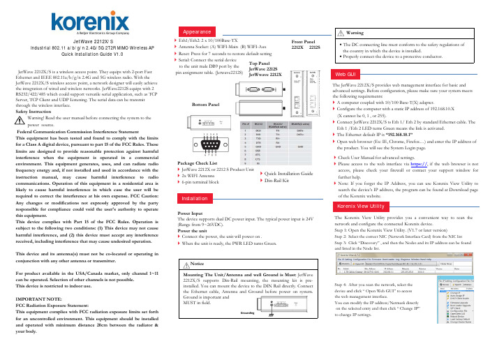
JetWave 2212X/S is a wireless access point. They equips with 2-port Fast Ethernet and IEEE 802.11a/b/g/n 2.4G and 5G wireless radio. With the JetWave 2212X/S wireless access point, a network designer will easily achieve the integration of wired and wireless networks. JetWave2212S equips with 2 RS232/422/485 which could support versatile serial application, such as TCP Server, TCP Client and UDP Listening.The serial data can be transmit through the wireless interface.Safety InstructionWarning!Read the user manual before connecting the system to the power source.Federal Communication Commission Interference StatementThis equipment has been tested and found to comply with the limits for a Class A digital device,pursuant to part 15of the FCC Rules.These limits are designed to provide reasonable protection against harmful interference when the equipment is operated in a commercial environment.This equipment generates,uses,and can radiate radio frequency energy and,if not installed and used in accordance with the instruction manual,may cause harmful interference to radio communications.Operation of this equipment in a residential area is likely to cause harmful interference in which case the user will be required to correct the interference at his own expense.FCC Caution:Any changes or modifications not expressly approved by the party responsible for compliance could void the user's authority to operate this equipment.This device complies with Part 15of the FCC Rules.Operation is subject to the following two conditions:(1)This device may not cause harmful interference,and (2)this device must accept any interference received,including interference that may cause undesired operation.This device and its antenna(s)must not be co-located or operating in conjunction with any other antenna or transmitter.For product available in the USA/Canada market,only channel 1~11can be operated.Selection of other channels is not possible.This device is restricted to indoor use.IMPORTANT NOTE:FCC Radiation Exposure Statement:This equipment complies with FCC radiation exposure limits set forth for an uncontrolled environment.This equipment should be installed and operated with minimum distance 20cm between the radiator &your body.The Korenix View Utility provides you a convenient way to scan the network and configure the connected Korenix device.Step 1: Open the Korenix View Utility. (V1.7 or later version)Step 2: Select the correct NIC (Network Interface Card) from the NIC listStep 3: Click “Discovery” , and then the Nodes and its IP address can be found and listed in the Node list.Step 4: After you scan the network, select the device and click “ Open Web GUI” to access the web management interface.You can modify the IP address/Netmask directly on the selected entry and then click “ Change IP” to change IP settings.JetWave 2212X/SIndustrial 802.11 a/b/g/n 2.4G/5G 2T2R MIMO Wireless APQuick Installation Guide V1.0InstallationPower InputThe device supports dual DC power input. The typical power input is 24V (Range from 9~26VDC).Power the unit❝Connect the power,the unit will power on .❝When the unit is ready,the PWR LED turns Green.Korenix View UtilityThe JetWave 2212X/S provides web management interface for basic and advanced settings. Before configuration, please make sure your system meets the following requirements:❝A computer coupled with 10/100 Base-T(X) adapter.❝Configure the computer with a static IP address of 192.168.10.X (X cannot be 0, 1, or 255).❝Connect JetWave 2212X/S t o Eth 1/ Eth 2 by standard Ethernet cable. The Eth 1 /Eth 2 LED turns Green means the link is activated. ❝The Ethernet default IP is “192.168.10.1”❝Open web browser (Ex: IE, Chrome, Firefox…) and enter the IP address ofthe product. You will see the System Login page.Web GUIFront Panel 2212X 2212SNoticeMounting The Unit/Antenna and well Ground is Must:JetWave 2212X/S supports Din-Rail mounting,the mounting kit is pre-installed.You can mount the device to the DIN Rail directly.Connect the Ethernet cable,Antenna andGround beforepower on system.Ground is importantand MUST in field.❝Quick Installation Guide ❝Din-Rail Kit❝Eth1/Eth2:2x 10/100Base-TX❝Antenna Socket:(A)WIFI-Main (B)WIFI-Aux ❝Reset:Press for 7seconds to restore default setting ❝Serial:Connect the serial deviceto the unit male DB9port by thepin assignment table.(Jetwave2212S)Package Check List❝JetWave 2212X or 2212S Product Unit ❝2x WIFI Antenna ❝6-pin terminal blockGroundingWarning•The DC connecting line must conform to the safety regulations of the country in which the device is installed.•Properly connect the device to a protective conductor.Bottom PanelTop PanelJetWave 2212SJetWwave 2212X❝Check User Manual for advanced settings.❝Please access to the web interface via https://,if the web browser is not access,please check your firewall or contact your support window for further help.❝Note:If you forget the IP Address,you can use Korenix View Utility to search the device’s IP address,the program can be found at Download page of the Korenix website .AppearanceKorenix View Utility 软件为用户提供一种便捷的方式用于检索网络设备, 并可对Korenix 设备进行相关配置Step 1: 开启Korenix View Utility (V1.7 或更新版本)Step 2: 在NIC 清单中选择正确的NIC(网卡接口)Step 3: 点击”Discovery” , 列表中会颢示网络节点及其IP 地址Step 4:检索到所有网络设备以后,选择某台设备开单击”Open Web GUI”可通过Web 登录管理界面。
- 1、下载文档前请自行甄别文档内容的完整性,平台不提供额外的编辑、内容补充、找答案等附加服务。
- 2、"仅部分预览"的文档,不可在线预览部分如存在完整性等问题,可反馈申请退款(可完整预览的文档不适用该条件!)。
- 3、如文档侵犯您的权益,请联系客服反馈,我们会尽快为您处理(人工客服工作时间:9:00-18:30)。
尊敬的用户: 感谢您使用Honeywell智能灯光系列产品!本公司谨向您承 诺以下服务: 1. 壹年免费保修:正常使用情况下,Honeywell 智 能灯光系列产品因质量故障,第一年(以霍尼 韦尔发票之日起 12 个月)免费维修。 2. 以下情况,不属于保修范围:人为原因造成的 设备故障、因使用环境不符合本产品要求造成 的故障、因不可抗力造成的产品损坏、无保修 卡、产品已过保修期等。 3. 对未经本公司或当地客户中心允许、擅自拆卸 Honeywell 智能灯光系列产品各组成部件的, 本公司将不再承担产品的免费保修责任。 4. 第三方(包括经销商、服务商)对用户所做的 超出本保修卡范围的承诺(口头或书面)由该 第三方负责兑现。 为确保您的消费权益,更好地享受我们的服务,请您保管好此 保修卡。
1. 长按遥控器上的【设置】键约 5 秒,当遥控器上的状态指示灯 闪烁时松开。 此时遥控器进入编程模式。
-7-
Honeywell
2. 在状态指示灯停止闪烁前,依 次按遥控器上的【删除】键和 数字键 1,若状态指示灯熄灭, 则操作成功。
设置场景
添加场景灯光 场景,在智能家居环境中定义为室内灯光和窗帘的特定状态。 添加场景,即建立实际场景与遥控器上场景按键的对应关系, 使用户可以通过遥控器上场景键控制室内场景变换。 要成功添加整个场景,必须将场景中所有灯光(由 HRMS 系 列无线控制器控制)和窗帘(由 HRMS-2131 窗帘控制器控制)依 次添加到遥控器对应场景键中。
控制器停止鸣叫、按键指 示灯停止闪烁,且 遥控器状态指示灯熄灭。
则操作成功。 此路灯光被成功添加至“会客”场景键,且为打开(或关闭)状态。
- 10 -
Honeywell
删除场景灯光 删除场景,即解除遥控器上场景键对实际场景的控制。 以下步骤以删除上述“会客”场景为例对删除场景灯光操作进 行说明。
1. 使用 HRMS-2112D 智能无线控制器或 HRMS-2191 无线遥控器对 应数字键打开(或关闭)要添加到“会客”场景键的那路灯光。 2. 长按控制器上对应按键约 5 秒,当控制器鸣响且按键指示 灯闪烁时松开。 此时控制器进入编程模式。
注意:
按下按键时指示灯状态改变: “打开”“关闭”或“关闭”“打开”
以上条款的最终解释权归霍尼韦尔安防(中国)有限公司所有。
Honeywell Security
亚太区总部 Honeywell Security Asia Pacific
中国上海市遵义路 100 号虹桥上海城 A 座 35 楼 35F Tower A, City Center, 100 Zun Yi Road, Shanghai 200051, China 电话(TEL):+86 21-22196888 传真(FAX):+86 21-62370740
2. 当控制器处于编程模式时,长 按遥控器上【设置】键约 5 秒,当遥控器上的状态指示灯 闪烁时松开。 此时遥控器进入编程模式。
-5-
Honeywell
3. 在控制器上按键指示灯和遥控 器上状态指示灯停止闪烁前, 依次按遥控器上的【添加】键 和数字键 1,若:
控制器停止鸣叫、按键指 示灯停止闪烁,且 遥控器状态指示灯熄灭。
则操作成功。 此时数字键 1 与 HRMS-2112D 智能无线控制器第一个按键建立一 一对应关系,用户可使用遥控器上数字键 1 控制 HRMS-2112D 智 能无线控制器第一个按键连接的那路灯光。
编程成功后或者在进入编程模式后等待 30 秒且无任何按键 操作,控制器与遥控器会自动退出编程模式。 注意 对已被编程的数字键进行再次编程会覆盖原有的灯光设置, 原灯光会被删除。 用户最多可添加 9 路灯光(数字键 1~9)。
-4-
Honeywell
1. 长按控制器上第一个按键约 5 秒,当控制器鸣响且按键指示灯 闪烁时松开。 此时控制器进入编程模式。
注意:
按下按键时指示灯状态改变: “打开”“关闭”或“关闭”“打开” 进入编程模式后指示灯状态恢复:“关闭”“打开”或“打开”“关闭”
通讯地址及邮编:___________________________________________ 经销商信息:_______________________________________________ 维修记录 1 2 3 4 全国统一客服热线:400-8800-330 故障原因 维修结果 维修日期
1. 长按无线遥控器的【设置】键 约 5 秒,当遥控器上的状态指 示灯闪烁时松开。 此时遥控器进入编程模式。
2. 在状态指示灯停止闪烁前,依 次按遥控器上的【删除】键和 【会客】键,若状态指示灯熄 灭,则操作成功。
- 11 -
Honeywell
技术参数
-1-
Honeywell
产品安装图
HRMS-2112D 智能无线控制器安装过程如下图所示: 1. 2. 使用安装螺丝通过螺丝孔将底板固定到墙体 86 盒中。 将前面板扣合到安装好的内面板上。
螺丝孔 前面板
安装螺丝
底板
-2-
Honeywell
功能说明
手控功能
HRMS-2112D 智能无线控制器按键采用轻触式设计,轻按按 键,即可手动控制灯光的开启和关闭。
注意
控制器按键在灯灭时亮起、灯亮时熄灭,便于用户夜间操作。
遥控功能
HRMS-2191 无线遥控器(简称“遥控器”,如下图所示)可 用于远程控制 HRMS-2112D 智能无线控制器(简称“控制 器”)。通过在遥控器与控制器之间编程,可将控制器连接的灯光 添加到遥控器上的数字键或场景键,使遥控器能够远程控制灯光的 开启、关闭和场景变换。
-8-
Honeywell
本说明书仅对“将 HRMS-2112D 智能无线控制器控制的场景 灯光添加到遥控器场景键”进行说明。有关场景窗帘和其他 HRMS 系列无线控制器控制的场景灯光的添加过程,请参考相关 用户使用说明书。 以下步骤以“将某路灯光添加到“会客”场景键”为例对 HRMS-2112D 智能无线控制器的添加场景灯光功能进行说明。
Honeywell
© 2010 Honeywell International Inc.
进入编程模式后指示灯状态恢复:“关闭”“打开”或“打开”“关闭”
-9-
Honeywell
3. 当控制器处于编程模式时,长 按无线遥控器的【设置】键约 5 秒,当遥控器上的状态指示灯 闪烁时松开。 此时遥控器进入编程模式。 4. 在面板按键指示灯和状态指示 灯停止闪烁前,依次按遥控器 上的【添加】键和【会客】 键,若
-3-
Honeywell
注意:有关 HRMS-2191 无 线遥控器的各项说明,详见 《HRMS-2191 无线遥控器 使用说明书》。
灯光设置
添加灯光 添加灯光,即通过编程建立 HRMS-2191 无线遥控器某个数字 键与 HRMS-2112D 智能无线控制器某个按键之间的一一对应关 系,使用户可以通过遥控器上该数字键远程控制对应按键连接的那 路灯光。 以下步骤以“添加 HRMS-2112D 智能无线控制器第一个按键 连接的灯光到遥控器上数字键 1”为例对添加灯光操作进行说明。
Honeywell
产品说明
HRMS-2112D 智能无线控制器是 Honeywell 智能灯光系列产 品之一,与 HRMS-2191 无线遥控器搭配使用,是现代家居智能化 的理想选择。
产品图示
HRMS-2112D 智能无线控制器采用双线(零线与火线)供电 模式,接线方式应严格参照下图。
- 12 -
Honeywell
中国RoHS
根据信息产业部等部委颁布的《电子信息产品污染控制管理办 法》及相关标准的要求,本产品相关信息如下: 1. 产品的环保使用期限为 10 年,保证该环保使用期限的安装及 使用注意事项见产品使用手册; 2. 产品中有毒有害物质或元素的名称及含量见下表:
Honeywell
Honeywell智能灯光系列
HRMS-2112D 智能无线控制器
使用说明书
Байду номын сангаас
使用产品之前,请仔细阅读本说明书。 请妥善保管本说明书以备后用。
© 2010 Honeywell International Inc. All rights reserved. / Document 800-05383 Rev. A1
- 13 -
Honeywell智能灯光系列
保 修 卡
产品名称:_________________ 产品序列号:_______________ 客户名称:_________________ 产品型号:_________________ 购买日期:_________________ 客户电话:_________________
-6-
Honeywell
删除灯光 删除灯光,即解除 HRMS-2191 无线遥控器某个数字键与 HRMS-2112D 智能无线控制器某个按键之间的一一对应关系,从 而使用户不能利用遥控器上该数字键远程控制对应按键连接的那路 灯光。 以下步骤以“删除遥控器上数字键 1 保存的灯光”为例,对删 除灯光操作进行说明。
HRMS-2112D 智能无线控制器
工作电压 负载最大功率 负载最小功率 工作温度 工作湿度 接收灵敏度 负载类型 220~240VAC 50~60Hz 1000W/路 无限制 -10℃~+55℃ ≤90%RH -100dbm 白炽灯/卤素灯/节能灯/荧光灯
注意事项
1. 2. 3. 4. 5. 6. 请联系专业技术人员进行安装、拆卸等操作。 请勿带电操作。 请勿将本产品安装在洗漱间、浴室等潮湿环境内。 安装前请测试负载是否短路,负载短路会导致无线控制器损 坏。 无线控制器每路负载功率之和不能大于所能负载最大功率。 无线控制器所接负载功率须大于所能负载最小功率,否则可能 导致无线控制器不工作。