光电感烟2251b-TB说明书
光电感烟探测器基础知识 图文 民熔

光电感烟探测器民熔烟光电感烟探测器内部采用离子式烟雾传感,离子式烟雾传感器是一种技术先进,工作稳定可靠的传感器,被广泛运用到各种消防报警系统中,性能远优于气敏电阻类的火灾报警器。
民熔光电感烟探测器广泛用于饭店、旅馆、教学楼、办公楼的厅堂、卧室、办公室电子计算机房、通讯机房、电影或电视放映室等民熔光电感烟探测器采用进口传感器同时可检测PM2.5,不同于市面的火灾烟雾报警器,抗误报,抗水蒸汽,准确识别香烟颗粒。
优选ABS材料,有良好的防火阻燃性可拆卸底座设计,方便固定和取下真材实料用的放心简单又方便,迅速作出反馈光电感烟探测器也是点型探测器,它是利用起火时产生的烟雾能够改变光的传播特性这一基本性质而研制的。
根据烟粒子对光线的吸收和散射作用。
光电感烟探测器又分为遮光型和散光型两种。
一般的点型光电感烟探测器属于散光型的,线型光束探测器是用的遮光型的。
工作原理光电感烟火灾探测器的工作原理是一感光电极处于激光照射下发生电信号,当火灾烟雾遮蔽激光时,电极失电,发出报警信号。
点型光电感烟探测器的红外发光元件与光敏元件(光子接收元件)在其探测室内的设置通常是偏置设计。
二者之间的距离一般在20-25mm.在正常无烟的监视状态下,敏元件接收不到任何光,包括红外发光元件发出的光。
在烟粒子进入探测室内时.红外发光元件发出的光则被烟粒子散射或反射到光敏元件上,并在收到充足光信号时,便发出火灾报警,这种火灾探测方法通常被称做烟散射光法。
点型光电感烟探铡器通常不采用烟减光原理工作.因为无烟和火灾情况之间的典型差别仅有0.09%变化这种小的变化会使探测器极易受到外部环境的不利影响。
线型光束感烟探测器通常是由分开安装的、经调准的红外发光器和收光器配对组成的;其工作原理是利用烟减少红外发光器发射到红外收光器的光束光量米判定火灾,这种火灾探测方法通常被称做烟减光法。
区别光电感从实际使用方面来看.二者的区别是.点型光电感烟探测器适用于设有小型空间的建筑.即适用于天棚高度在12m 以下的房间,探测面积为60-80m2,线型光束感烟探测器适用于设有高天棚和大型空间的建筑,一只线型光束感烟探测器的保护面积相当于18只点型光电感烟探测器的保护面积,特别适用于探测位于地面处的阴燃火。
2251BRA智能照电子烟感设备说明书

SS-400-0051I56-3578-0002251BRA Intelligent Photoelectric Smoke Sensor with Remote Test Capability in Duct ApplicationsINSTALLATION AND MAINTENANCE INSTRUCTIONSBEFORE INSTALLINGThis sensor must be installed in compliance with the control panel system installation manual. The installation must meet the requirements of the Au-thority Having Jurisdiction (AHJ). Sensors offer maximum performance when installed in compliance with CAN/ULC-S524.GENERAL DESCRIPTIONModel 2251BRA is a plug-in type smoke sensors that combines a photo-electronic sensing chamber with addressable-analog communications. The sensor transmits an analog representation of smoke density over a communi-cation line to a control panel. Rotary-decade switches are provided for setting the sensor’s address.Two LEDs on the sensor are controlled by the panel to indicate sensor status. An output is provided for connection to an optional remote LED annunciator (P/N RA400ZA/RA100ZA).When 2251BRA is used in duct applications with a DNRA, testing can be done remotely using approved System Sensor test accessories, eliminating the need for a test coil.NOTE: Only System Sensor approved accessories may be used with the 2251BRA.The 2251BRA requires compatible addressable communications to function properly. Connect the 2251BRA sensor to listed-compatible control panels only.SPACINGSystem Sensor recommends spacing sensors in compliance with CAN/ULC-S524. In low air flow applications with smooth ceilings, space sensors 30 feet apart. For specific information regarding sensor spacing, placement, and special applications, refer to CAN/ULC-S524 or the System Smoke Detector Application Guide, available from System Sensor.Duct Applications: 2251BRA is listed for use in ducts. See Duct Applications Guide A05-1004-XX.WIRING GUIDEAll wiring must be installed in compliance with the Canadian Electrical Code, applicable local codes, and any special requirements of the Authority Hav-ing Jurisdiction. Proper wire gauges should be used. The installation wires should be color-coded to limit wiring mistakes and ease system troubleshoot-ing. Improper connections will prevent a system from responding properly in the event of a fire.Remove power from the communication line before installing sensors.1. Wire the sensor base (supplied separately) per the wiring diagram, Figure 1.2.S et the desired address on the sensor address switches, see Figure 2.3.I nstall the sensor into the sensor base. Push the sensor into the base while turning it clockwise to secure it in place.4.A fter all sensors have been installed, apply power to the control unit and activate the communication line.5.T est the sensor(s) as described in the TESTING section of this manual.SPECIFICATIONSOperating Voltage Range: 15 to 32 VDCStandby Current:300µA @ 24 VDC (one communication every 5 seconds with LED blink enabled)Maximum Alarm Current (LED on:) 6.5 mA @ 24 VDCOperating Humidity Range: 10% to 93% Relative Humidity, Non-condensing Operating Temperature Range: 32°F to 120°F (0°C to 49°C) 2251BRA–4°F to 158°F (–20°C to 70°C) 2251BRA in duct applications Height: 2.0˝ (51 mm) installed in B210LPA BaseDiameter: 6.1˝ (155 mm) installed in B210LPA Base; 4.1˝ (104 mm) installed in B501 Base Weight:5.2 oz. (147 g)Dust covers provide limited protection against airborne dust particles dur-ing shipping. Dust covers must be removed before the sensors can sensesmoke. Remove sensors prior to heavy remodeling or construction.FIGURE 1. WIRING DIAGRAM:CAUTION: DO NOT LOOP WIRE C0100-01Note: Only System Sensor approved accessories may be used with the 2251BRA.FIGURE 2. ROTARY DECADE ADDRESS SWITCHES:TENS ONES98765432109876543210C0146-00TAMPER-RESISTANCEModel 2251BRA includes a tamper-resistant capability that prevents its re-moval from the bracket without the use of a tool. Refer to the base manual for details on making use of this capability.TESTINGBefore testing, notify the proper authorities that the system is undergoing maintenance, and will temporarily be out of service. Disable the system to prevent unwanted alarms.All sensors must be tested after installation and periodically thereafter. Test-ing methods must satisfy the Authority Having Jurisdiction (AHJ). Sensors offer maximum performance when tested and maintained in compliance with CAN/ULC-S536.The sensor can be tested in the following ways:A. Functional: Magnet Test (P/N M02-04-01 or M02-09-00)T his sensor can be functionally tested with a test magnet. The test mag-net electronically simulates smoke in the sensing chamber, testing the sensor electronics and connections to the control panel. 1. H old the test magnet in the magnet test area as shown in Figure 3.6581 Kitimat Road, Unit 6, Mississauga, Ontario L5N-3T51.800.SENSOR2; Fax: 905-812-0771www.systemsensor.ca2. The sensor should alarm the panel.T wo LEDs on the sensor are controlled by the panel to indicate sensor status. Coded signals, transmitted from the panel, can cause the LEDs to blink, latch on, or latch off. Refer to the control panel technical docu-mentation for sensor LED status operation and expected delay to alarm.B. Smoke EntryThe GEMINI model 501 aerosol generator can be used for smoke entry testing. Set the generator to represent 4%/ft to 5%/ft obscuration as de-scribed in the GEMINI 501 manual. Using the bowl shaped applicator, apply aerosol until the panel alarms.A dditionally, canned aerosol simulated smoke (canned smoke agent) may be used for smoke entry testing of the smoke detector. Tested and approved aerosol smoke products are:MANUFACTURER MODEL Home Safeguard Industries 25S SDi SOLOA4SDiSMOKESABRE-01When used properly, the canned smoke agent will cause the smoke detector to go into alarm. Refer to the manufacturer’s published instructions for proper use of the canned smoke agent.Canned aerosol simulated smoke (canned smoke agent) formulas will vary by manufacturer. Misuse or overuse of these products may have long term adverse effects on the smoke detector. Consult the canned smoke agent manufacturer’s published instructions for any further warnings or caution statements.C. R emote Test2251BRA can be remotely tested using the RTS451KEYA or RTS-151KEYA test accessories. Refer to the DNRA manual for wiring dia-grams. Maximum test response time may be up to two communications from the panel.A sensor that fails any of these tests should be cleaned as described under CLEANING, and retested. If the sensor fails after cleaning, it must be replaced.When testing is complete, restore the system to normal operation and notify the proper authorities that the system is back in operation.FIGURE 3. TEST MAGNET POSITION:C0145-02CLEANINGBefore removing the detector, notify the proper authorities that the smoke detector system is undergoing maintenance and will be temporarily out of service. Disable the zone or system undergoing maintenance to prevent un-wanted alarms.1. Remove the sensor to be cleaned from the system.2.R emove the sensor cover by pressing firmly on each of the four removal tabs that hold the cover in place.3. V acuum the screen carefully without removing it. If further cleaning isrequired continue with Step 4, otherwise skip to Step 7.4. R emove the chamber cover/screen assembly by pulling it straight out.5. U se a vacuum cleaner or compressed air to remove dust and debrisfrom the sensing chamber.6. R einstall the chamber cover/screen assembly by sliding the edge overthe sensing chamber. Turn until it is firmly in place.7. R eplace the cover using the LEDs to align the cover and then gentlypushing it until it locks into place.8. Reinstall the detector.9. Test the detector as described in TESTING.10. Reconnect disabled circuits.11. Notify the proper authorities that the system is back on line.FIGURE 4. SENSOR ASSEMBLY:C0215-03SPECIAL NOTE REGARDING SMOKE DETECTOR GUARDSSmoke detectors are not to be used with detector guards unless the combina-tion has been evaluated and found suitable for that purpose.SS-400-005 2 I56-3578-000©2009 System SensorSystem Sensor warrants its enclosed smoke detector to be free from defects in materials and work-manship under normal use and service for a period of three years from date of manufacture. System Sensor makes no other express warranty for this smoke detector. No agent, representative, dealer, or employee of the Company has the authority to increase or alter the obligations or limitations of this Warranty. The Company’s obligation of this Warranty shall be limited to the repair or replacement of any part of the smoke detector which is found to be defective in materials or workmanship under normal use and service during the three year period commencing with the date of manufacture. After phon-ing System Sensor’s toll free number 800-SENSOR2 (736-7672) for a Return Authorization number, send defective units postage prepaid to: System Sensor, Returns Department, RA #__________, 6581FCC STATEMENTThis device complies with part 15 of the FCC Rules. Operation is subject to the following two conditions: (1) This device may not cause harmful interference, and (2) this device must accept any interference received, including interference that may cause undesired operation.NOTE: This equipment has been tested and found to comply with the limits for a Class B digital device, pursuant to Part 15 of the FCC Rules. These limits are designed to provide reasonable protection against harmful interference in a residential installation. This equipment generates, uses and can radiate radio frequency energy and, if not installed and used in accordance with the instructions, may cause harmful interference to radio communications. However, there is no guarantee that interference will not occur in a particular installation. If this equipment does cause Harmful interference to radio or television reception, which can be determined by turning the equipment off and on, the user is encouraged to try to correct the interference by one or more of the following measures: – Reorient or relocate the receiving antenna. – Increase the separation between the equipment and receiver. – Connect the equipment into an outlet on a circuit different from that to which the receiver is connected. – Consult the dealer or an experienced radio/TV technician for help.This Class B digital apparatus complies with Canadian ICES-003.THREE-YEAR LIMITED WARRANTYKitimat Road, Unit 6, Mississauga, Ontario L5N-3T5. Please include a note describing the malfunction and suspected cause of failure. The Company shall not be obligated to repair or replace units which are found to be defective because of damage, unreasonable use, modifications, or alterations occur-ring after the date of manufacture. In no case shall the Company be liable for any consequential or incidental damages for breach of this or any other Warranty, expressed or implied whatsoever, even if the loss or damage is caused by the Company’s negligence or fault. Some states do not allow the exclusion or limitation of incidental or consequential damages, so the above limitation or exclusion may not apply to you. This Warranty gives you specific legal rights, and you may also have other rights which vary from state to state.Please refer to insert for the Limitations of Fire Alarm Systems。
光电感烟火灾探测器安装使用说明书

1、概述
JTY-GD-XY(Ⅱ)型点型光电感烟火灾探测器是依据GB4715-2005《点型感烟火灾探测器》利用红外光散射原理探测烟雾,从而预报初期火灾。
本产品因采用超薄型结构,表面安装技术,使用红外传感器,因而不含放射性,环境适应性好,不易误报,使用更加安全可靠。
2、产品特点
.二总线,可编址。
.微功耗,环境适应性好。
.通用底座,超薄造型。
.防风尘,防昆虫。
.报警确认灯:巡检时红色闪亮,报警时红色常亮,故障时灯熄灭。
3、技术指标
电源电压:DC24V
静态电流:<0.4mA。
报警电流:<2.0 mA。
外型尺寸:101.5*48(含底座)。
安装孔距:62-73 mm
全部重量:200g。
4、接线方法
5、安装调试
安装探测器底座时,应注意使报警确认灯位于房间内外便于观察的方向。
在安装接线正确无误后,方可通电加烟试验。
在足够的烟进入探测器后,一般应在
10秒内报警。
6、使用维护
探测器的应用设计(保护面积、应用场合、使用环境、安装位置、选用导线等)应符合GBJB6-88火灾报警系统设计规范。
系统正常运行后,每季度应进行现场喷烟检查,发现失灵者应及时更换。
每年清除迷宫及纱网上的灰尘一次。
JTY-GD-SA1201 光电感烟火灾报警器 说明书
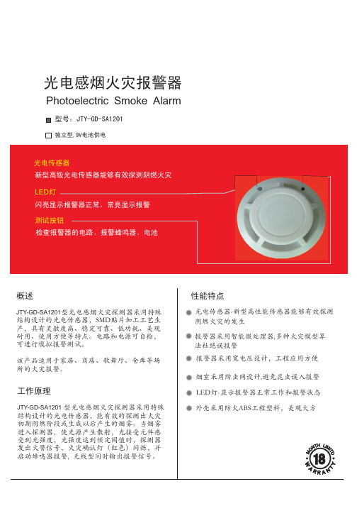
Photoelectric Smoke Alarm
型号:JTY-GD-SA1201
独立型,9V电池供电
光电传感器 新型高级光电传感器能够有效探测阴燃火灾 LED灯 闪亮显示报警器正常,常亮显示报警 测试按钮 检查报警器的电路、报警蜂鸣器、电池
概述
JTY-ቤተ መጻሕፍቲ ባይዱD-SA1201型光电感烟火灾探测器采用特殊 结构设计的光电传感器,SMD贴片加工工艺生 产,具有灵敏度高、稳定可靠、低功耗、美观 耐用、使用方便等特点。电路和电源可自检, 可进行模拟报警测试。
安装指南:
在天花板上相距36mm 的位置上打两个直径 6mm的安装孔,用塑料膨胀管和螺钉固定探测 器的底板。 打开探测器的上盖,将9V层叠电池安装在探测 器中。注意:如电池的方向接反,探测器将不能 正常工作,还可能损坏探测器。 扣好探测器上盖,按住自检按钮,探测器指示等 快速闪烁并发出报警声,则报警器工作正常。如 不正常,应检查电池是否安装正确或电压过低 (低于7.5V)。 探测器测试好后,将探测器扣在底板上,顺时针 旋紧到位。
该产品适用于家居、商店、歌舞厅、仓库等场 所的火灾报警。
工作原理
JTY-GD-SA1201 型光电感烟火灾探测器采用特殊 结构设计的光电传感器,能有效的探测出火灾 初期阴燃阶段或生成以后产生的烟雾。当烟雾 进入探测器,使光源产生散射,光接受元件感 受到光强度,光强度达到预定阈值时,探测器 发出火警信号,火灾确认灯(红色)闪烁,并 启动蜂鸣器报警, 无线型同时输出报警信号。
性能特点
光电传感器-新型高性能传感器能够有效探测 阴燃火灾的发生 报警器采用智能微处理器,多种火灾模型算 法杜绝误报警 报警器采用宽电压设计,工程应用方便 烟室采用防虫网设计,避免昆虫误入报警 LED灯-显示报警器正常工作和报警状态 外壳采用防火ABS工程塑料,美观大方
dd点型光电感烟火灾探测器使用说明书

版本号:1001060724点型光电感烟火灾探测器使用说明书一、总述1、点型光电感烟火灾探测器是与我公司智能二总线火灾报警控制器配套使用的产品,为二总线工作方式。
2、 适用于火灾发生时有烟雾产生,正常情况下无烟雾的场所。
3、 对燃烧时产生的白色烟雾较敏感。
4、 符合GB 4715-93《点型感烟火灾探测器技术要求及试验方法》要求,性能稳定可靠。
二、使用方法1、 底座接线示意图:图中: L+/ L- :控制器输出报警回路信号正/负端2、 接线方式:二线制L+(3)端和L-(1)端。
3、 地址编码:将探测器正确装入编码器的编码底座上,将编码器调整为编码功能,并且设置正确的地址,按下编码键,完成地址编码。
三、技术参数1、 工作电压:24V (脉冲调制) 工作电流:<0.5mA2、 外形尺寸:Φ100×40 mm3、 工作环境:温度:-10℃~+55℃ 相对湿度:≤95%(40℃±2℃ 无凝露)4、 保护面积:≤60m 2 (层高<6m )L 版本号:1001060724四、注意事项1、本探测器不适用于燃烧时完全产生黑烟的场所,以及燃烧时无烟或极少产生烟的场所。
2、探测器地址设定且确认与控制器连接无误后接通电源,当在控制器中登录此探测器地址后,该探测器的红色指示灯将闪烁。
3、当探测器处于火警状态下时,红色指示灯常亮。
只有在系统复位或短暂掉电且又重新上电后,探测器上红色指示灯才由常亮恢复闪烁状态。
4、同一报警回路,属于同类地址空间的产品不允许具有相同的地址,否则系统可能无法正常工作。
5、随探测器附带的防尘罩,在现场安装结束未开通使用前,请勿过早摘除,以免探测器受到污染。
6、探测器离空调出风口的安装距离至少1.5米。
7、安装应符合GB 50116-92《火灾自动报警系统施工及验收规范》中的规定。
五、维护和检测1、从产品出厂之日起一年内,按规定要求正常使用的探测器,如因材料或制造工艺的缺陷而失效,深圳市泛海三江电子有限公司将负责免费维修或更换。
GEM-SMK 高质量光电烟感设备说明书

1Description: The GEM-SMK is a high-quality photoelectric smoke detector with built-in supervised digitally-coded radio transmitter. It is compatible with Napco’s GEM-RECV Series supervised security receivers that monitor alarms, restores, low battery and status.During normal operation, the LED on the GEM-SMK flashes once every 30 seconds. As soon as smoke is detected, the GEM-SMK sounds a local alarm and the transmitter sends an alarm signal to the supervised receiver. The alarm signal is repeated every 10 seconds thereafter as long as smoke is still present. A restore report is sent when the smoke detec-tion chamber clears. Supervisory status reports are sent from the GEM-SMK every hour.Coding switches are not required or used in the GEM-SMK. Each transmitter is assigned a unique identification code number at the factory.R333 Bayview Avenue Amityville, New York 11701For Sales and Repairs, (800) 645-9445 For Technical Service, (800) 645-9440Publicly traded on NASDAQ Symbol: NSSC© NAPCO 2008The smoke detector and transmitter are powered by one 9-volt alkaline battery and one 3-volt lithium battery (supplied) which can power the unit for at least one year. If the battery voltage drops below normal, a low-battery report will be sent to the re-ceiver with any status or alarm transmission. If a low-battery condition is indicated, always replace both batteries.NOTE: Temperature and humidity extremes may reduce the life of the batteries. In addition, the GEM-SMK detector is designed to prevent re-mounting to the mounting plate without the detec-tor battery installed.Use Only Batteries Specified In Marking. Use of A Different Battery May Have A Detrimental Effect On Detector Operation.Step 1. Remove the mounting plate. Remove theGEM-SMK mounting plate by turning the plate counter-clockwise and pulling it up.Step 2. Identify components. Examine the GEM-SMK to identify the component locations.LIFT TO REMOVE MOUNTING PLATETWIST MOUNTING PLATE TO UNLOCKLIFT HERE TO OPENRF ID# LABELLIFT HERE TO OPEN3-VOLT BATTERY COMPARTMENT9-VOLT BATTERY COMPARTMENTStep 3. Install battery. Place one 3-volt lithium Dura-cell DL123A, Varta/Power One Model CR123A or Panasonic CR123A in its battery compart-ment, observing correct polarity. Connect one 9-volt Duracell MN-1604 alkaline battery and place it into its battery compartment. Install batteries and enroll the GEM-SMK into the control panel before mounting .(–)BATTERY COMPARTMENTS(+)continued2 NOTE: Smoke detectors are not to be used withdetector guards unless the combination has beenevaluated and found suitable for that purpose.Step 4. Pick smoke-detector location. Referring tothe NFPA standard on page 3, select a suitablelocation to mount the GEM-SMK.Note:Mounting the GEM-SMK on foil-backedwallpaper is NOT recommended because theradio range will be reduced.Step 6. Map the GEM-SMK Transmitter. Referring tothe instructions for the panel and keypad in use,enter the following:•the zone to which the transmitter will be mapped;•the 6-digit RF identification number/1-digit check-sum number printed on the transmitter (include allnumbers and/or letters and leading zeros, if any);and•the transmitter point number ("1").NOTE: In fire alarm installations, the control panelmust be programmed to activate the fire alarm bells orhorns upon detection of a fire.Silence ModeAllows the temporary disabling of the unit. Press and holdthe Test button for more than 10 seconds to enter SilenceMode.Silencing the UnitTo silence the unit during a smoke alarm, press andhold the Test button for 10 seconds to temporarily silencethe unit for 5 minutes.Low Battery WarningSounder chirps and the LED flashes simultaneously.Maintenance WarningThe smoke detector will warn that it must be cleanedwhen the unit chirps (without a simultaneous LED flash)but the LED flashes between chirps. To clean the smokedetector, vacuum the outside of the unit at least once ayear (preferably every six months) using a soft brush at-tachment. Do not attempt to clean the unit in any otherway. If this maintenance procedure fails to clean the unitsufficiently, call for service and/or replace the unit.Step 8. Test system weekly with unit mounted. Ifthe system is monitored, notify central stationof impending test. Press and hold the Test but-ton for 30 seconds after the local alarmsounds. The sounder will turn on while the buttonis pressed and the LED will flash every half-second. Verify that the GEM-SMK triggers thecorrect zone on the control panel and that thecorrect report is sent to the central station.HOLD BUTTON FOR AT LEAST30 SECONDS AFTER LOCALALARM SOUNDS TO SEND ANALARM TRANSMISSIONStep 7. Attach the GEM-SMK to mounting plate.Match up alignment tabs on detector andplate. Turn detector clockwise until it locksinto place.TWISTDETECTORCLOCKWISETO LOCK TOMOUNTINGPLATEMATCH UPALIGNMENTTABS DININGROOMKITCHENSMOKEDETECTORBEDROOM BEDROOMLIVINGROOM BEDROOMPRESS AND HOLDTEST BUTTONA smoke alarm should belocated between the sleepingarea and the rest of the familyliving unit.In family living units with morethan one sleeping area, a smokealarm should be provided foreach separate sleeping area. Indicates required smoke detector Indicates optional smoke detector if door is not provided between Living and Recreation rooms.A smoke detector should belocated on each storyNFPA STANDARD FOR SMOKE-DETECTOR LOCATION The GEM-SMK should be installed in accordance with the National Fire Protec-tion Association (NFPA) Standard 72. For your information, the National Fire Pro-tection Association's Standard 72, reads as follows:11.5.1 One- and Two-Family Dwelling Units.11.5.1.1 Smoke Detection Where required by applicable laws, codes, or stan-dards for the specified occupancy, approved single- and multiple-station smoke alarms shall be installed as follows: (1) In all sleeping rooms. Exception: Smoke alarms shall not be required in sleeping rooms in existing one- and two- family dwelling units. (2) Outside of each separate sleeping area, in immediate vicinity of the sleeping rooms. (3) On each level of the dwelling unit, including basements. Exception: In existing one- and two-family dwelling units, approved smoke alarms powered by batteries are permitted.11.8.3 Are More Smoke Detectors Desirable? The required number of smoke detectors might not provide reliable early warning protection for those areas sepa-rated by a door from the areas protected by the required smoke detectors. For this reason, it is recommended that the householder consider the use of additional smoke detectors for those areas for increased protection. The additional areas include the basement, bedrooms, dining room, furnace room, utility room, and hall-ways not protected by the required smoke detectors. The installation of smoke detectors in kitchens, attics (finished or unfinished), or garages is not normally rec-ommended, as these locations occasionally experience conditions that can result in improper operation.There exist certain situations where the presence of a smoke alarm is not ef-fective, such as smoking in bed, the testing of gas leaks with a flame or for warning against the existence of high carbon monoxide levels inside a family living unit. Current studies have shown smoke alarms may not awaken all sleeping individuals; it is therefore the responsibility of individuals in the household that are capable of assisting others to provide assistance to those who may not be awakened by the alarm sound and to provide assistance to those who may be incapable of safely evacuating the area unassisted.For family living units with one or more split levels (i.e., adjacent levels with less than one full story separation between levels), a smoke detector required as above shall suffice for an adjacent lower level, including basements.Exception: Where there is an intervening door between one level and the adja-cent lower level, a smoke detector shall be installed on the lower level. •Ceiling-mounted smoke alarms should be located in the center of the room or hall, or not less than 4 inches from any wall. When the detector is mounted ona wall, the top of the detector should be 4 to 12 inches from the ceiling.•Do not install smoke alarms where normal ambient temperatures are above 100°F (37.8°C), below 40°F (4.4°C) or greater than 92% humidity unless the alarm has been determined to be capable of being used at installation points with higher or lower ambient temperatures. Also, do not locate alarm in front of air conditioners, heating registers, or other locations where normal air circula-tion will keep smoke from entering the detector. Installing smoke detectors in kitchens, garages or furnace rooms is NOT recommended.All installation wiring must be in accordance with the provisions of Article 210 of the National Electrical Code, ANSI / NFPA 70. All protected premises fire alarm systems shall be maintained and tested (at least once every month) in accordance with NFPA 72. FIRE PREVENTION AND ESCAPEThe purpose of an early warning smoke alarm is to detect the presence of fire in its early stages, and sound an alarm giving the occupants more time to exit the premise before the smoke reaches a dangerous concentration level.Fires start even with the best of housekeeping and fire-prevention procedures. Fire is an unexpected event. Early warning detection alerts occupants in time to act.KNOW FIRE HAZARDS. No detection device can protect life in all situa-tions. Therefore, safeguards should be taken to avoid such potentially dangerous situations as smoking in bed, leaving children home alone, cleaning with flammable liquids such as gasoline.The best fire protection is minimizing fire hazards through proper storage of materials and general good housekeeping techniques. A cluttered basement, attic, or other storage area is an open invitation to fire.Careless use of combustible materials and electrical appliances, or overloading of electrical outlets are other prime causes in starting fires.It is most important that explosive and/or fast-burning materials be eliminated from the home if at all possible.Even after proper precautions have been taken, fires can start. Be prepared.IN CASE OF FIRE. Leave immediately. Don’t stop to pack or search for valuables. In heavy smoke, hold your breath and stay low -- crawl if necessary. The clearest air is usually at the floor.If you have to go through a closed door, carefully feel the door and door knob to see if undue heat is present. If they seem relatively cool, brace your foot against the bottom of the door with your hip against the door and one hand against the top edge. Open it slightly. If a rush of hot air is felt, slam the door quickly and latch it. Unvented fire tends to build up considerable pressure. Be sure all the household realizes and understands this danger.Use your neighbor’s phone or a street fire alarm box. The job of extinguishing the fire should be left to the professionals. Too many unforeseen things can occur when inexperienced people try to extinguish afire.BE PREPARED. Perform fire drills regularly. Use them to assure recogni-tion of an alarm signal. For your protection, simulate different circumstances (smoke in hall, in living room, etc.). Then have everyone react to the situation.Draw a floor plan and show two exits from each room. Frequently, a knotted rope or ladder from a window will serve this purpose. It is important that children be instructed carefully, because they tend to hide in times of crisis.It is imperative that one meeting place outside the home be established. You should insist that everyone meet there during an alarm. This will eliminate the trag-edy of someone reentering the house for a missing member who is actually safe.If you have children and/or invalids residing in your household, you can help your fire department. Most fire departments have window decals available for use in children’s or invalid’s bedrooms. Properly used, these decals will quickly identify sleeping quarters of these individuals and show the department where to look first for members of your household.Additional information on Household Fire Warning is available at nominal cost from The National Fire Protection Agency, Batterymarch Park, Quincy, MA 02269. Re-quest Standard No. NFPA 72.3NAPCO SECURITY SYSTEMS, INC. (NAPCO) warrants its products to be free from manufacturing defects in materials and workmanship for thirty-six months following the date of manufacture. NAPCO will, within said period, at its option, repair or replace any product failing to operate correctly without charge to the original purchaser or user.This warranty shall not apply to any equipment, or any part thereof, which has been repaired by others, improperly installed, improperly used, abused, altered, damaged, subjected to acts of God, or on which any serial numbers have been altered, defaced or removed. Seller will not be responsible for any dismantling or reinstallation charges. THERE ARE NO WARRANTIES, EXPRESS OR IMPLIED, WHICH EXTEND BEYOND THE DESCRIPTION ON THE FACE HEREOF. THERE IS NO EXPRESS OR IMPLIED WARRANTY OF MERCHANT ABILITY OR A WARRANTY OF FITNESS FOR A PARTICULAR PURPOSE. ADDITIONALLY, THIS WARRANTY IS IN LIEU OF ALL OTHER OBLIGATIONS OR LIABILITIES ON THE PART OF NAPCO.Any action for breach of warranty, including but not limited to any implied warranty of merchant ability, must be brought within the six months following the end of the warranty period.IN NO CASE SHALL NAPCO BE LIABLE TO ANYONE FOR ANY CONSEQUENTIAL OR INCIDENTAL DAMAGES FOR BREACH OF THIS OR ANY OTHER WARRANTY, EXPRESS OR IMPLIED, EVEN IF THE LOSS OR DAMAGE IS CAUSED BY THE SELLER'S OWN NEGLIGENCE OR FAULT.In case of defect, contact the security professional who installed and maintains your security system. In order to exercise the warranty, the product must be returned by the security professional, shipping costs prepaid and insured to NAPCO. After repair or replacement, NAPCO assumes the cost of returning products under warranty. NAPCO shall have no obligation under this warranty, or otherwise, if the product has been repaired by others, improperly installed, improperly used, abused, altered, damaged, subjected to accident, nuisance, flood, fire or acts of God, or on which any serial numbers have been altered, defaced or removed. NAPCO will not be responsible for any dismantling, reassembly or reinstallation charges.This warranty contains the entire warranty. It is the sole warranty and any prior agreements or representations, whether oral or written, are either merged herein or are expressly canceled. NAPCO neither assumes, nor authorizes any other person purporting to act on its behalf to modify, to change, or to assume for it, any other warranty or liability concerning its products. In no event shall NAPCO be liable for an amount in excess of NAPCO's original selling price of the product, for any loss or damage, whether direct, indirect, incidental, consequential, or otherwise arising out of any failure of the product. Seller's warranty, as herein above set forth, shall not be enlarged, diminished or affected by and no obligation or liability shall arise or grow out of Seller's rendering of technical advice or service in connection with Buyer's order of the goods furnished thereunder.NAPCO RECOMMENDS THAT THE ENTIRE SYSTEM BE COMPLETELY TESTED WEEKLY.Warning: Despite frequent testing, and due to, but not limited to, any or all of the following; criminal tampering, electrical or communications disruption, it is possible for the system to fail to perform as expected. NAPCO does not represent that the product/system may not be compromised or circumvented; or that the product or system will prevent any personal injury or property loss by burglary, robbery, fire or otherwise; nor that the product or system will in all cases provide adequate warning or protection. A properly installed and maintained alarm may only reduce risk of burglary, robbery, fire or otherwise but it is not insurance or a guarantee that these events will not occur. CONSEQUENTLY, SELLER SHALL HAVE NO LIABILITY FOR ANY PERSONAL INJURY, PROPERTY DAMAGE, OR OTHER LOSS BASED ON A CLAIM THE PRODUCT FAILED TO GIVE WARNING. Therefore, the installer should in turn advise the consumer to take any and all precautions for his or her safety including, but not limited to, fleeing the premises and calling police or fire department, in order to mitigate the possibilities of harm and/or damage.NAPCO is not an insurer of either the property or safety of the user's family or employees, and limits its liability for any loss or damage including incidental or consequential damages to NAPCO's original selling price of the product regardless of the cause of such loss or damage.Some states do not allow limitations on how long an implied warranty lasts or do not allow the exclusion or limitation of incidental or consequential damages, or differentiate in their treatment of limitations of liability for ordinary or gross negligence, so the above limitations or exclusions may not apply to you. This Warranty gives you specific legal rights and you may also have other rights which vary from state to state.NAPCO LIMITED WARRANTYNAPCO SECURITY GROUP333 Bayview Avenue, Amityville, New York 11701 For Sales and Repairs, (800) 645-9445 For Technical Service, (800) 645-9440Publicly traded on NASDAQ Symbol: NSSC4。
光电感烟探测器使用说明书
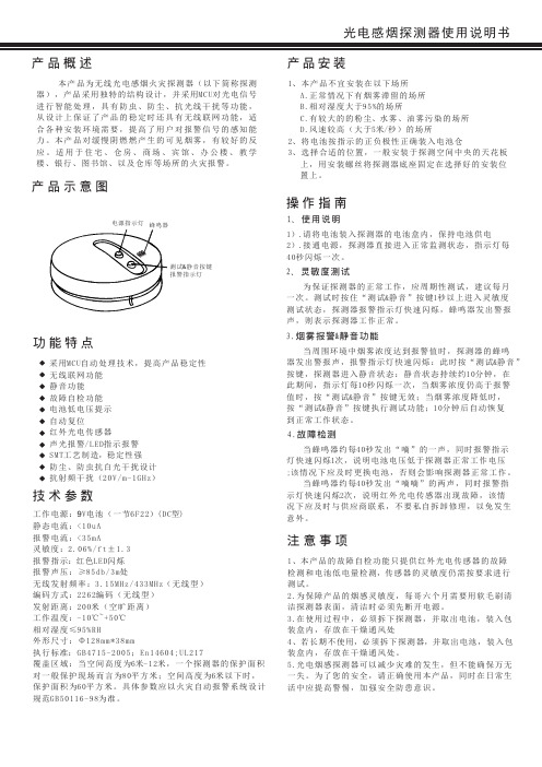
当 蜂 鸣 器 约 每4 0秒 发 出 “ 嘀 嘀 ” 的 两 声 , 同 时 报 警 指 示 灯 快 速 闪 烁2次 , 说 明 红 外 光 电 传 感 器 出 现 故 障 , 该 情 况下应及时与供应商联系,不要私自拆卸修理,以免发生 意外。
注意事项
1 、本 产 品 的 故 障 自 检 功 能 只 提 供 红 外 光 电 传 感 器 的 故 障 检 测 和 电 池 低 电 量 检 测,传 感 器 的 灵 敏 度 仍 需 按 要 求 进 行 测试。 2 .为 保 障 产 品 的 烟 感 灵 敏 度 , 每 哥 六 个 月 需 要 用 软 毛 刷 清 洁探测器表面,清洁时必须先断开电源。 3 .在 使 用 过 程 中 , 必 须 拆 下 探 测 器 , 并 取 出 电 池 , 装 入 包 装盒内,存放在干燥通风处 4 、若 长 期 不 使 用,必 须 拆 下 探 测 器,并 取 出 电 池 , 装 入 包 装盒内,存放在干燥通风处。 5 .光 电 烟 感 探 测 器 可 以 减 少 灾 难 的 发 生 , 但 不 能 确 保 万 无 一失。为了您的安全,请正确使用本产品,同时在日常生 活中应提高警惕,加强安全防患意识。
技术参数
工作电 源 :9V电池(一节6F22)(DC型) 静态电 流 :< 1 0 u A 报警电 流 :< 3 5 m A 灵敏度 :2 . 0 6 % / f t ± 1 . 3 报警指 示:红 色L E D闪 烁 报警声 压 : ≥8 5 d b / 3 m处 无线发 射 频 率 :3 . 1 5 MH z / 4 3 3 M H z( 无 线 型 ) 编码方 式 :2 2 6 2编 码 (无 线 型 ) 发射距 离 :2 0 0米 ( 空旷 距 离 ) 工作温 度 :- 1 0℃~ + 5 0℃ 相对湿 度 ≤9 5 % R H 外形尺 寸 : Φ1 2 8 m m * 3 8 m m 执行标 准: G B 4 7 1 5 - 2 0 0 5 ; E n 1 4 6 0 4 ; U L 2 1 7 覆盖区 域 : 当 空 间 高 度为6米- 1 2米 , 一 个 探 测 器 的 保护面积 对一般 保 护 现 场 而 言 为8 0平 方 米 ; 空 间 高 度 为6米 以下时, 保护面 积 为6 0平 方 米 。具 体 参 数 应 以 火 灾 自 动 报 警 系统设计 规范GB 5 0 1 1 6 - 9 8为 准 。
光电式感烟报警器说明
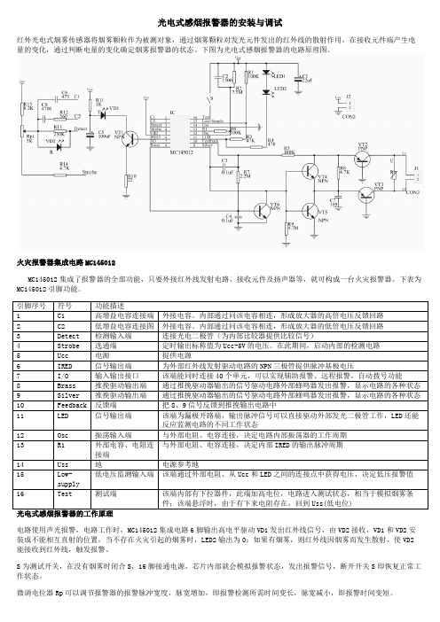
光电式感烟报警器的安装与调试红外光电式烟雾传感器将烟雾颗粒作为被测对象,通过烟雾颗粒对发光元件发出的红外线的散射作用,在接收元件端产生电量的变化,通过判断电量的变化确定烟雾报警器的状态。
下图为光电式感烟报警器的电路原理图。
火灾报警器集成电路MC145012MC145012集成了报警器的全部功能,只要外接红外线发射电路、接收元件及扬声器等,就可构成一台火灾报警器。
下表为MC145012引脚功能。
电路使用声光报警,电路工作时,MC145012集成电路6脚输出高电平驱动VD1发出红外线信号,由VD2接收,VD1和VD2安装成不能相互直射的位置,当不存在火灾引起的烟雾时,LED2输出为0;如果有烟雾,则红外线因烟雾而发生散射,使VD2能接收到红外线,触发报警。
S为测试开关,在没有烟雾时闭合S,16脚接通电源,芯片内部就会模拟报警状态,发出报警信号,断开开关S即恢复正常工作状态。
微调电位器Rp可以调节报警器的报警脉冲宽度,脉宽增加,即报警检测所需时间变长,脉宽减小,即报警时间变短。
C6 C8 R12组成增益调节电路,可以调节系统的放大倍数,也可以作为一种调节灵敏度的方法。
在有烟雾时,由于烟雾颗粒造成的光电二极管的变化很小,因此内置放大电路,调整C6 C8 R12的参数,即可调整放大器的增益倍数,达到调节灵敏度的效果。
其中C6作为粗调元件单独使用,C8作为增益的微调元件,需要与R12配合使用。
时钟电路为RC电路,由R2 R6 C2组成,向12脚提供周期性的脉冲信号。
电源低压报警电路是在系统电源电压过低时发出报警信号,提示及时更换电池,R1 R3串联在电源电压和11脚之间,向15脚提供电源最低允许电压。
当电源电压小于最低允许电压时,9脚输出一个高电平,推动复合三极管输出,提示报警,调节R1与R2比值大小,可以改变电源最低允许电压值。
元件清单。
光束感烟产品安装使用说明书(3.3C)
目录一、产品概述 (1)二、特点 (1)三、工程设计 (1)四、技术参数 (3)五、安装、调试 (5)1. 探测器外观示意图 (5)2. 安装 (5)3. 连线 (6)4. 调试 (6)5. 检测 (7)六、一般性故障的查询表 (7)七、日常维护 (8)八、售后服务 (8)一、产品概述JTY-HF-YJLH103型线型光束感烟火灾探测器(以下简称探测器)由发射器和接收器组成,采用不受烟色影响的红外线减光方式工作。
单片计算机通过在探测器内置CPU的固化运算程序,使探测器具备了较强的分析判断能力,可自动完成对外界环境变化补偿并判断火警/故障状态,通过声光和输出信号等手段给出状态指示。
特别适用于无遮挡空间的高层建筑群,如各类商场、厅堂馆所、古建筑物、大型车间、仓库、隧道、及各种建筑的夹层、闷顶等,凡是在火灾形成前有烟雾出现的场所均可使用本产品。
当烟雾进入探测区内时,由于光束被遮挡使收到的红外光的强度降低。
当烟雾达到一定浓度使红外光的强度低于设定的阈值时,探测器报火警,启动蜂鸣器、点亮红色指示灯。
本设备功能执行GB14003-2005国家标准中相关条款。
二、特点探测器内所有器件、导线均采用直焊方式连接,无任何接插件,防止温/湿度变化带来的影响,保证探测器在高空长期可靠运行;密闭外壳,具有防尘防水性;可大角度安装,更好的适用于在不平行、弧形、斜型等墙面,拱顶、 斜顶等建筑;轴向单一预压紧调试螺母,调试方便且紧固时不会改变已调好角度; 根据现场调试情况自动修正灵敏度,保证探测器的一致性;接收器设有红、黄指示灯及音响指示,工程调试简便可靠;具有光照自动监测补偿功能,有较强的抗日光干扰能力;具有积尘自动监测补偿功能;多种输出接口,与各厂家报警输入模块配套方便;三、工程设计根据《新编消防设计规范汇编(一)》、《火灾自动报警系统设计规范》GB50116-98中的规定:第7.3.1条:线型火灾探测器的选择:无遮挡大空间或有特殊要求的场所,宜选择红外光束感烟探测器。
星纵物联 GS524N 独立式光电感烟火灾探测报警器 用户手册说明书

独立式光电感烟火灾探测报警器GS524N用户手册安全须知感谢您使用星纵物联独立式光电感烟火灾探测报警器,使用产品前请务必仔细阅读本说明书,并按照所提供的有关操作步骤进行,避免因误操作而损坏本机或发生其他意外。
请妥善保管本手册,以便日后需要时使用。
厦门星纵物联科技有限公司秉承全面品管、持续改善的原则,以科技创新、客户满意为目标,不断致力于产品改进、提高产品性能,公司保留本产品改进但不通知客户的权利。
在使用本产品前,请根据产品出厂清单仔细核对附件、产品合格证及用户保修卡是否齐全,若发现不全,请立即与销售商或厂家联络。
本产品自售出之日起十二个月内,凡用户遵守贮存、运输及使用要求时,当产品质量低于技术指标,可凭保修单享受免费维修。
因违反操作规定和要求而造成的损坏、非我司指定的特约技术服务部维修引起的故障或由于不可抗拒因素引起的产品质量问题,我司将进行收费维修。
如果用户不按照使用说明书的操作步骤操作本产品,并且擅自安装、私拆、更换产品零部件,由此产生的责任由用户自己承担。
非专业人员请勿开盖!如果您对我们提供的产品和服务有任何疑问或不满(包括产品技术、质量、安装维修、服务态度、收费标准等问题),请您及时联络我们,我们将会对您的意见妥善处理。
产品符合性声明GS524N符合CCC基本要求和其他相关规定,执行GB20517-2006标准。
版权所有©2011-2022星纵物联保留所有权利。
如需帮助,请联系星纵物联技术支持:邮箱:*********************电话:************传真:************总部地址:厦门市集美区软件园三期C09栋深圳:深圳市南山区高新南一道TCL大厦A709日期版本描述2022.6.30V1.0第一版目录一、产品简介 (5)1.1产品介绍 (5)1.2产品亮点 (5)二、产品结构介绍 (5)2.1包装清单 (5)2.2外观概览 (6)2.3产品尺寸(mm) (6)三、产品功能状态 (7)四、产品自检测试 (8)五、安装说明 (9)5.1安装位置 (9)5.2安装步骤 (10)5.3安装方法 (11)六、保养及清洁 (11)七、故障排除 (12)八、设备入网 (12)8.1入网准备 (12)8.2入网配置 (13)九、通信协议 (16)9.1上行数据 (16)9.2下行数据 (17)一、产品简介1.1产品介绍GS524N是一款具备声光报警功能的LoRaWAN®无线烟雾探测报警器。
海湾JTY-GD-G3T点型光电感烟火灾探测器说明书
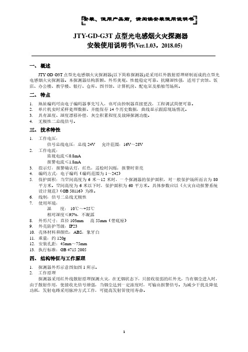
安装、使用产品前,请阅读安装使用说明书JTY-GD-G3T点型光电感烟火灾探测器安装使用说明书(Ver.1.03,2018.05)一、概述JTY-GD-G3T点型光电感烟火灾探测器(以下简称探测器)是采用红外散射原理研制而成的点型光电感烟火灾探测器。
本探测器结构新颖、外形美观、性能稳定可靠、抗潮湿性强,适用于宾馆、饭店、办公楼、教学楼、银行、仓库、图书馆、计算机房、配电室及船舶等场所。
二、特点1.地址编码可由电子编码器事先写入,也可由控制器直接更改,工程调试简便可靠。
2.单片机实时采样处理数据、并能保存14个历史数据,曲线显示跟踪现场情况。
3.具有温度、湿度漂移补偿,灰尘积累程度及故障探测功能。
4.无极性二总线信号。
三、技术特性1.工作电压:信号总线电压:总线24V 允许范围:16V~28V2.工作电流:监视电流≤0.8mA报警电流≤1.8mA3.指示灯:报警确认灯,红色,巡检时闪烁,报警时常亮4.编码方式:电子编码(编码范围为1~242)5.保护面积:当空间高度为6米~12米时,一个探测器的保护面积,对一般保护场所而言为80平方米。
空间高度为6米以下时,保护面积为60平方米。
具体参数应以《火灾自动报警系统设计规范》(GB 50116)为准。
6.线制:信号二总线无极性7.使用环境:温度:-10℃~+55℃相对湿度≤95%,不凝露8.外形尺寸:直径103mm 高55mm(带底座)9.外壳防护等级:IP2310.壳体材料和颜色:ABS,象牙白11.重量:约120g12.安装孔距:45mm~75mm13.执行标准:GB 4715-2005四、结构特征与工作原理1.探测器外形示意图如图1所示。
2.工作原理探测器采用红外线散射原理探测火灾,在无烟状态下,只接收很弱的红外光,当有烟尘进入时,由于散射作用,使接收光信号增强,当烟尘达到一定浓度时,可输出报警信号。
为减少干扰及降低功耗,发射电路采用脉冲方式工作,可提高发射管使用寿命。
贝灵BL59A S12光电式烟雾检测电路说明书

带I/O的光电式烟雾检测电路BL59A/S12产品概述BL59A/S12是光电型烟雾检测电路,使用时外部配有一个红外探测腔。
电路工作时,先由芯片红外发射端IRED 控制的红外发光二极管周期性地发射红外线,接收端Detect 由一个光电二极管负责检测探测腔内烟雾颗粒散过来的红外线强度,如果有烟雾,光电二极管会微弱导通,从而在光电二极管的两端有一个微小的电压信号,此电压信号经芯片内部可变增益放大器放大,通过内部的一个电压比较器比较后得到一个烟雾报警信号,再经过内部的控制电路使得蜂鸣器端口发出报警信号。
BL59A/S12可通过I/O脚与最多40个报警单元互连以实现共同报警。
BL59A/S12内置低电压报警功能和探测腔灵敏度退化报警功能。
低电压报警阈值可以通过外围电阻R6和R7来设置。
特点工作电压范围6~12V,典型为9V平均工作电流:8μA可通过I/O 脚与最多40 个报警单元互连以实现互联报警工作温度范围:-10~60℃封装形式:DIP16、SOP16和SOP16W应用领域光电型烟雾检测器管脚图管脚功能说明引脚序号 符 号输 入 /输出功能1 C1 外接电容,内部通过与该电容相连,形成放大器的高倍电压反馈回路2 C2 外接电容,内部通过与该电容相连,形成放大器的低倍电压反馈回路3 Detect I 烟雾检测端口4 Strobe O 参考电压端口,参考电平 = VDD - 5V5 VDD 电源6 IRED O 为外部作红外发射驱动器的 NPN 管提供脉冲基极电压。
7 I/O 该端能同时连接40个单元,实现远程报警8 Brass O 报警输出,驱动外部蜂鸣器9 Silver O 报警输出,驱动外部蜂鸣器10 Feedback I 蜂鸣器反馈信号输入端11 LED O 该端为漏极开路端,输出脉冲信号可直接驱动外部发光二极管工作12 OSC I 与外部电阻、电容连接,决定电路内部振荡器的振荡周期。
13 R1 与外部电阻、电容连接,决定内部电路IRED 的输出的脉冲周期。
智能光电感烟传感器HS1SA-Z用户手册说明书
Sloping CeilingMounting Position Installation Step 2Detector will enter the network mode by clicking “ ” in theFCC Warning:This equipment has been tested and found to comply with the limits for a Class B digital device, pursuant to part 15 of the FCC Rules. These limits are designed to provide reasonable protection against harmful interference in a residential installation. This equipment generates, uses and can radiate radio frequency energy and, if not installed and used in accordance with the instructions, may cause harmful interference to radio communications. However, there is no guarantee that interference will not occur in a particular installation. If this equipment does cause harmful interference to radio or television reception, which can be determined by turning the equipment off and on, the user is encouraged to try to correct the interference by one or more of the following measures:•Reorient or relocate the receiving antenna.•Increase the separation between the equipment and receiver.•Connect the equipment into an outlet on a circuit different from that to which the receiver is connected.•Consult the dealer or an experienced radio/TV technician for help. Caution: Any changes or modifications to this device not explicitly approved by manufacturer could void your authority to operate this equipment.This device complies with part 15 of the FCC Rules. Operation is subject to the following two conditions: (1) This device may not cause harmful interference, and (2) this device must accept any interference received, including interference that may cause undesired operation.。
海湾安全技术 GY-02 光电感烟探测器 说明书

GY-02光电感烟探测器安装使用说明书(Ver 1.0, 2003.04)目录一概述 (1)二特点 (1)三技术特性 (1)四结构特征与工作原理 (1)五安装与布线 (2)六维护保养 (3)七注意事项 (4)一概述本探测器运用了新型的散射技术采用进口光电器件提高了传感器的可靠性稳定性和一致性并采用独特的迷宫设计防虫防尘抗外界光线干扰性能良好产品结构新颖外型美观性能稳定可靠抗潮湿性强并具有良好的抗化学腐蚀性适用于宾馆库房等场所二特点本探测器为非编码型工作时直接接入直流电源即可工作探测器具有一对输出触点正常时断路报警后触点闭合并保持同时探测器上指示灯点亮断电后复位探测器采用定位底座具有唯一的安装方式三技术特性1.工作电压DC12V~DC28V2.工作电流监视电流<1mA报警动作电流<20mA3. 报警复位瞬间断电(5s MAX DC2.5V MAX)4.上电时间10s5.灵敏度0.32dB/m~0.51dB/m6.输出控制方式无源常开报警时闭合并自锁触点额定容量1A DC24V7.指示灯红色巡检时不亮报警时常亮8.保护面积当空间高度为6m12m一个探测器的保护面积对一般保护现场而言为80mm2空间高度为6m以下时保护面积为60mm2具体参数应以火灾自动报警系统设计规范GB50116-98为准9.线制有极性四线制10.使用环境温度-10+50相对湿度95% 不凝露11.外形尺寸直径103mm高度40mm (不包括定位底座)12.外壳防护等级IP4013.壳体材料和颜色ABS 象牙白14.重量119g15.安装孔距45mm~75mm16.执行标准Q/GST 16-2003四结构特征与工作原理1.探测器外形示意图见图1在正常情况下为降低功耗发射管采用间歇方式工作五安装与布线安装探测器之前接线极性准确无误型标准预埋盒其结构探测器中扣采用定位中扣其底部示意图见图3间接继电器输出使探测器具有唯一的安装位置A 个凸棱探测器定位中扣侧面C 处有一个缺口装配时将探测器缺口C 对准定位底座A 处顺时针旋转至B 处即可安装好探测器3. 布线方式可采用截面积不小于1.0mm 2的RV 或BVR 线六维护保养1. 探测器每年至少清洁一次以保证系统的正常运行2. 探测器在进行清洁之前应通知有关管理部门系统将进行维护会因此而临时停止工作同时应切断将进行维护的区域或系统的逻辑控制功能以免造成不必要的报警联动3.探测器应在即将调试前方可安装在安装前应妥善保管并应采取相应的防尘防潮防腐蚀措施4.工程上如发现探测器有经常性误报的现象则应对迷宫进行清洗必要时可更换迷宫5.每半年应进行一次模拟火警试验测试探测器是否工作正常七注意事项1.防尘罩必须在工程正式投入使用后方可摘下请妥善保管防尘罩以备后用2.防尘罩可以有效地限制灰尘进入探测器然而却不可能彻底杜绝空气中的浮尘微粒进入探测器内因此建议在进行土建施工装修或其它会产生灰尘的活动开始以前卸下探测器但必须通知有关管理部门3.在进行维护保养时应小心以避免损坏探测器4.在探测器周围0.5m内不应有遮挡物5.探测器至空调送风孔边的水平距离不应小于1.5m6.探测器至墙壁梁边的水平距离不应小于0.5m7.在宽度小于3m的内走道顶棚上设置探测器时宜居中布置探测器的安装间距不应超15m探测器距端墙的距离不应大于探测器安装间距的一半8.探测器宜水平安装如必须倾斜安装时倾斜角不应大于459.探测器底座应安装牢固其导线连接必须可靠10.探测器的确认灯应面向便于人员观察的主要入口方向。
博世Fire Alarm Systems F220 光电感烟探测器 产品说明书
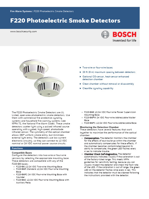
u Two-wire or four-wire basesu30 ft (9 m) maximum spacing between detectors u Optional CO-sensor, heat-sensor enhanced detection chamberu Clean chamber without removal or disassembly u CleanMe signaling capabilityThe F220 Photoelectric Smoke Detectors are UL Listed, open-area photoelectric smoke detectors. Use them with commercial fire protective signaling systems and household fire warning systems (see NFPA 72, the National Fire Alarm Code). These smoke detectors scatter light using a pulsed infrared source operating with a gated, high-speed, photodiode infrared sensor. The symmetry of the optical chamber allows 360° uniform smoke entry, but minimizes external light entry. The detectors use low current electronic circuitry, so they can connect to 12 VDC nominal or 24 VDC nominal power source circuits. FunctionsCompatible BasesConfigure the detectors into two-wire or four-wire versions by selecting the appropriate mounting base. These detectors are compatible with any of theF220‑B6 bases:•F220-B6 12/24 VDC Two‑wire Mounting Base•F220-B6R Standard 12/24 VDC Four‑wire MountingBase•F220-B6RS 24 VDC Four‑wire Mounting Base withSounder•F220-B6C 12/24 VDC Four‑wire Mounting Base with Auxiliary Relay•F220-B6E 12/24 VDC Four‑wire Power SupervisionMounting Base•F220-B6PM 24 VDC Four‑wire Addressable MasterBase•F220-B6PS 12/24 VDC Four‑wire Addressable Base Monitoring the Detection ChamberThese detectors have several features that work together to maximize the performance of the optical chamber:•Compensation: The detector monitors the chamberfor the effects of dust build-up within the chamberand automatically compensates for these effects. Ifthe chamber becomes contaminated beyond itsability to compensate, the green LED flashes every4 sec to indicate trouble.•Chamber Check Self-diagnostics: The detectorautomatically indicates visually if the calibration is out of the factory-listed range. This meets NFPAguidelines for sensitivity testing, because you canvisually inspect the detector and check the flash rate of the LED. If the calibration is out of range, the green LED on the detector flashes once every 4 sec. Thisindicates that the detector must be cleaned following the instructions provided with the detector.•CleanMe Mode: Indicates if the calibration is out of the factory-listed range by sending a trouble signal to the CleanMe-compatible control panel, if so programmed.•Chambermaid: The detector has a unique cleaning mechanism. Use the valve on the back of the detector to insert the nozzle of a can of clean, dry compressed air. Clean the chamber with a short (1 to 2 sec) blast of air.Heat and Carbon Monoxide EnhancementsThe detectors are available with an optional fixed-temperature heat sensor, a carbon monoxide (CO)sensor, or a combination of heat and CO sensors.These optional sensors enhance the operation of the smoke detector by reducing false alarms.•Carbon Monoxide: Without the presence of CO, a normal byproduct of combustion, the detection chamber is half as sensitive to smoke as a standard commercial photoelectric smoke chamber. This reduces false alarms. When the sensor detects CO,the detection chamber's sensitivity to smokeincreases so it equals or exceeds that of a standardcommercial photoelectric smoke chamber.NoticeThe F220-PTHC detects carbon monoxide (CO) as a component of a fire. It is not a CO detector and cannot activate an alarm in the presence of CO only.•Heat: When the heat sensor detects a temperature rise, the photoelectric chamber becomes more smoke sensitive. The heat sensor initiates an alarm if the ambient temperature exceeds +135°F (+57°C).Dual-color LEDA dual-color LED indicator flashes green every 8 sec when the detector has power and the smoke sampling circuitry is working. If CleanMe is enabled, the green LED double flashes (two flashes a half second apart)every 8 sec to indicate normal operation. The LED turns red if an alarm is sent. After the alarm condition clears, reset the detector by interrupting its power. If the chamber becomes contaminated beyond its ability to compensate, the green LED flashes every 4 sec to indicate trouble.Test FunctionsThe F220 Photoelectric Smoke Detectors feature a unique magnet operation and sensitivity test function.Test the detector's operation by placing the magnet next to the detector's LED for three consecutive flashes. This causes the detector to send an alarm.Placing a magnet next to the detector's LED for atleast one red flash but less than three flashes activates the detector's sensitivity mode.Tamper DetectionWhen detector heads are correctly installed in any of the F220-B6 bases, the positive power line provides tamper detection. The control panel initiates a troublesignal if a detector is removed from its base. A mechanical tamper lock comes with each base to prevent unauthorized head removal.Installation/configuration notesCompatible Control PanelsAddressable Systems: compatible with addressable systems controlled by B9512G, B8512G, D9412GV4,D7412GV4, D9412GV3, D7412GV3, D9412GV2,D7412GV2, D9412G, or D7412G Control Panels or the D9124 Fire Alarm Control Panel when used with the F220-B6PM or F220-B6PS Addressable Detector Bases.Two-wire: Bosch Security Systems, Inc. makes no claim written, oral, or implied that the F220Photoelectric Smoke Detectors work with any two-wire control panels except those specified in the Control Panel Compatibility chart in the Technical Service Note (P/N: 4998148185).Four-wire: compatible with all UL Listed four-wirecontrol panels. Refer to the control panel's installation instructions for proper end-of-line (EOL) resistor selection.Mounting the BasesNoticeConsult NFPA‑72 for proper detector placement.Depending on local regulations, the bases can be surface mounted directly on four-inch square or octagonal electrical boxes and single-gang switch boxes.NoticeThe volume of any electrical box used should be large enough to accommodate the number and size of conductors as specified by the National Electrical Code or any local authorities having jurisdiction (AHJ).Loop SupervisionLoop supervision requires one D275 or F220-B6E perloop when using F220‑B6R/B6C bases and is supervised by the control panel.Wiring the BasesRefer to the F220 Series Detectors withF220‑B6/C/E/R Bases Installation Instructions (P/ N: 4998138694), the F220 Series Detectors withF220‑B6RS Bases Installation Instructions (P/N: F01U029847), or the F220-B6PS/M Installation Instructions (P/N: 4998149982) for detailed wiring instructions.Technical specificationsEnvironmentalMechanicalElectricalVoltage (standby)TrademarksAll hardware and software product names used in this document are likely to be registered trademarks and must be treated accordingly.F220‑PTHC Photoelectric Smoke Detector with +135°F (+57°C) Heat and Carbon Monoxide Sensors Photoelectric detector head with heat and CO sensor augmentation only; requires base.Order number F220-PTHCF220‑PTH Photoelectric Smoke Detector with +135°F (+57°C) Heat SensorPhotoelectric detector head with heat sensor only; requires base.Order number F220-PTHF220‑P Photoelectric Smoke DetectorPhotoelectric detector head only; requires base. Order number F220-PAccessoriesD275 Power Supervision ModuleLine supervision device for four-wire fire detection circuitsOrder number D275DRA‑5 Remote Annunciator (5 VDC)Designed to provide remote annunciation of alarms for a number of Bosch smoke and heat detectorsOrder number DRA-5DT‑2 Detector Removal ToolUse the DT‑2 to remove, replace, or test the detector headOrder number DT-2F220‑B6 12/24 VDC Two‑wire BaseStandard base for two‑wire (12 VDC or 24 VDC system) applications.Order number F220-B6F220‑B6R Standard 12/24 VDC Four‑wire Base Standard base for four‑wire (12 VDC or 24 VDC) detector systems.Order number F220-B6RF220‑B6RS 24 VDC Four‑wire Detector Base with Soun-derFour-wire detector base with sounder for use with the F220 Photoelectric Smoke and Heat Detectors.Order number F220-B6RSF220‑B6C 12/24 VDC Four‑wire Base with Auxiliary Form C RelayFour‑wire base with a normally‑open (NO) alarm loop relay and a set of auxiliary contacts (Form C).Order number F220-B6CF220‑B6E 12/24 VDC Four‑wire Power Supervision Base with End‑of‑line Power Monitoring RelayFour‑wire base with a normally‑open (NO) alarm relay and an EOL power supervision relay.Order number F220-B6EF220‑B6PM 24 VDC Four‑wire Addressable Multiple De-tector BaseThe multiple detector base provides an address on theFACP data expansion circuit for its detector and up toan additional 19 detectors. It accepts the F220Photoelectric Smoke Detector Heads and HeatDetector Heads.Order number F220-B6PMF220‑B6PS 12/24 VDC Four‑wire Addressable Single De-tector BaseThe single detector base provides an address on theFACP data expansion circuit for its detector. It acceptsthe F220 Photoelectric Smoke Detector Heads andHeat Detector Heads.Order number F220-B6PSRepresented by:North America:Europe, Middle East, Africa:Asia-Pacific:China:Latin America and Caribbean:Bosch Security Systems, Inc. 130 Perinton Parkway Fairport, New York, 14450, USA Phone: +1 800 289 0096 Fax: +1 585 223 9180***********************.com Bosch Security Systems B.V.P.O. Box 800025617 BA Eindhoven, The NetherlandsPhone: + 31 40 2577 284Fax: +31 40 2577 330******************************Robert Bosch (SEA) Pte Ltd, SecuritySystems11 Bishan Street 21Singapore 573943Phone: +65 6571 2808Fax: +65 6571 2699*****************************Bosch (Shanghai) Security Systems Ltd.203 Building, No. 333 Fuquan RoadNorth IBPChangning District, Shanghai200335 ChinaPhone +86 21 22181111Fax: +86 21 22182398Robert Bosch Ltda Security Systems DivisionVia Anhanguera, Km 98CEP 13065-900Campinas, Sao Paulo, BrazilPhone: +55 19 2103 2860Fax: +55 19 2103 2862*****************************© Bosch Security Systems 2016 | Data subject to change without notice 2701164683 | en, V9, 04. Mar 2016。
点型光电感烟火灾探测器说明书

点型光电感烟火灾探测器说明书
日期
北京利达防火保安设备有限公司文件名称:安装使用说明书
文件编号:LD—FJ—58—005 版号:A 页码:2
五、结构与安装尺寸
底座
探测器
36
Φ54
六、接线示意图
二总线二总线
可接编码型接LD128E系列
探测器火灾报警控制器
]
探测器及底座接线图
七、布线要求
探测器回路二总线宜选用截面积≥1、0mm2 的双色双绞铜芯线,穿金属管或阻燃管敷设,也可采用控制电缆,如:KVV-2×0、75;连接导线的长度应以总导线电阻<70Ω为限,否则应增大导线的线径。
八、使用限制
★最大保护面积:50m2
★最大安装高度:8m
九、齐套性
探测器1个
底座1个
合格证1个
铭牌1个
防尘罩1个
更改标记更改单号更改人日期
产品名称点型光电感烟火灾探测器
产品型号JTY-GD-LD3000E。
博世BOSCH 无线,光电式烟Sensor检测器型号文件说明书

CALIFORNIA DEPARTMENT OF FORESTRY & FIRE PROTECTIONOFFICE OF THE STATE FIRE MARSHALFIRE ENGINEERING - BUILDING MATERIALS LISTING PROGRAMLISTING SERVICELISTING No.7272-1615:0214Page 1 of 1CATEGORY:7272 -- SMOKE DETECTOR-SYSTEM TYPE-PHOTOELECTRIC LISTEE:BOSCH SECURITY SYSTEMS130 Perinton Parkway, Fairport, NY 14450Contact: Jon Wolski (585) 678-3323 Fax (585) 678-3263Email:*******************.com DESIGN: Models RF280, RF280S, RF280TH, and RF280THS wireless, photoelectric smoke detector.Models RF280TH and RF280THS employs an integral 135° fixed temperature, thermistortype, heat sensor. The heat sensor is intended for use only as a supplement to the smokedetector and is NOT approved for use in lieu of required heat detectors. Refer to listee's datasheet for additional detailed product description and operational considerations.RATING:Two 3V Lithium BatteriesINSTALLATION: In accordance with listee's printed installation instructions, applicable codes & ordinancesand in a manner acceptable to the authority having jurisdiction.MARKING: Listee's name, model number, electrical rating, and UL label.APPROVAL: Listed as photoelectric smoke detectors for use with separately listed compatible fire alarmcontrol units and RT Receiver Model *RF3224 (CSFM Listing No. 7167-1615:212). Refer tolistee’s Installation Instruction Manual for details.NOTE:The photoelectric type detectors are generally more effective at detecting slow , smolderingfires, which smolder for hours before bursting into flames. Sources of these fires may includecigarettes burning in couches or bedding. The ionization type detectors are generally moreeffective at detecting fast, flaming fires, which consume combustible materials rapidly andspread quickly. Sources of these fires may include paper burning in a waste container or agrease fire in the kitchen. *Corrected 01-20-2005July 01, 2013Date Issued:Listing Expires June 30, 2014Authorized By:Fire Engineering Division This listing is based upon technical data submitted by the applicant. CSFM Fire Engineering staff has reviewedthe test results and/or other data but does not make an independent verification of any claims. This listing is not an endorsement or recommendation of the item listed. This listing should not be used to verify correct operational requirements or installation criteria. Refer to listee’s data sheet, installation instructions and/or otherJAMES PARSEGIAN , Program Coordinator。
光束感烟产品安装使用说明书(3.3C)
目录一、产品概述 (1)二、特点 (1)三、工程设计 (1)四、技术参数 (3)五、安装、调试 (5)1.探测器外观示意图 (5)2.安装 (5)3.连线 (6)4.调试 (6)5.检测 (7)六、一般性故障的查询表 (7)七、日常维护 (8)八、售后服务 (8)编制审核批准一、产品概述JTY-HF-YJLH103型线型光束感烟火灾探测器(以下简称探测器)由发射器和接收器组成,采用不受烟色影响的红外线减光方式工作。
单片计算机通过在探测器内置CPU的固化运算程序,使探测器具备了较强的分析判断能力,可自动完成对外界环境变化补偿并判断火警/故障状态,通过声光和输出信号等手段给出状态指示。
特别适用于无遮挡空间的高层建筑群,如各类商场、厅堂馆所、古建筑物、大型车间、仓库、隧道、及各种建筑的夹层、闷顶等,凡是在火灾形成前有烟雾出现的场所均可使用本产品。
当烟雾进入探测区内时,由于光束被遮挡使收到的红外光的强度降低。
当烟雾达到一定浓度使红外光的强度低于设定的阈值时,探测器报火警,启动蜂鸣器、点亮红色指示灯。
本设备功能执行GB14003-2005国家标准中相关条款。
二、特点探测器内所有器件、导线均采用直焊方式连接,无任何接插件,防止温/湿度变化带来的影响,保证探测器在高空长期可靠运行;密闭外壳,具有防尘防水性;可大角度安装,更好的适用于在不平行、弧形、斜型等墙面,拱顶、斜顶等建筑;轴向单一预压紧调试螺母,调试方便且紧固时不会改变已调好角度; 根据现场调试情况自动修正灵敏度,保证探测器的一致性;接收器设有红、黄指示灯及音响指示,工程调试简便可靠;具有光照自动监测补偿功能,有较强的抗日光干扰能力;具有积尘自动监测补偿功能;多种输出接口,与各厂家报警输入模块配套方便;三、工程设计根据《新编消防设计规范汇编(一)》、《火灾自动报警系统设计规范》GB50116-98中的规定:第7.3.1条:线型火灾探测器的选择:无遮挡大空间或有特殊要求的场所,宜选择红外光束感烟探测器。
- 1、下载文档前请自行甄别文档内容的完整性,平台不提供额外的编辑、内容补充、找答案等附加服务。
- 2、"仅部分预览"的文档,不可在线预览部分如存在完整性等问题,可反馈申请退款(可完整预览的文档不适用该条件!)。
- 3、如文档侵犯您的权益,请联系客服反馈,我们会尽快为您处理(人工客服工作时间:9:00-18:30)。
个,热源距探测器保持 30cm 左右距离,以免损坏外壳。探测器只有在经过足够的时间冷却后,才
会复位。要确保探测器的每一个感温元件都经过单独测试。
2
I56-1909-00C
2 LEDS
测试磁铁 位置
C0145-00
维护保养
进行清洁前,通告有关管理部门感烟探测器系统将进行维护而临时停止工作。切断将进行维护的区域或系 统的逻辑控制功能,以免无为的报警联动。
每一探测器有两个发光二极管(LED)作为360O 全方位可见指示灯。作为可选附件的远程LED指示 器(门灯 ) 可以达到远程显示功能。 2251TB和2251TMB探测器是一种点型感烟、感温复合火灾探测器,既具有光 电探测室又具有在57.2℃时报警的定温探测器的功能。技Biblioteka 条件直径:155 mm
( 6.1 英寸 ) 装于B210LP底座
1
探测器可能探测不到建筑的其它楼层上所发生的火灾。因此,建筑的每一楼层都应装有探测器。
1
感烟探测器也有探测局限性。离子型探测器具有广泛的火灾探测功能,但其在探测快速燃烧及明火焰型的火情 方面比缓慢、阴燃型的火更好。光电探测器对阴燃火比对明焰火的探测效果更好。由于火情的发展各式各样,且 经常是对其蔓延无法预料,所以没有哪一种探测器效果总是最佳的。而对某一探测器而言,不能保证其总会对任 何种类的火情都产生及时报警。一般而言,对那些由于不充分的防范措施、猛烈的爆炸、泄漏的煤气、诸如清洗 稀释剂之类的可燃液体的不良储存和其它安全事故或人为纵火或儿童玩火所引起的火灾,不能指望探测器会及时 发出报警。用于高风速场合的感烟探测器会因为频繁和快速的空气交换稀释了烟的浓度而推迟报警。此外,高风 速的环境会产生更大的灰尘污染而需要频繁的维护保养。
A 功能测试:测试磁铁(M02-04-01 或 M02-09-00)
2251B、2251TB 和 2251TMB 型探测器可以用测试磁铁进行功能测试。测试磁铁会模拟探测室里
的烟来测试探测器工作是否正常。
1、 按图 3 所示,将一测试磁铁放置在正确位置。
2、 探测器向控制器发出报警信号
由控制器控制的 2 个 LED 显示探测器的工作状态。通过命令码发出的信号可使 LED 闪烁、锁
远程显示(门灯)
小心:勿将导线环绕在端子1或2下联接。应断开导线 后再连到端子上以提供对系统接线的监视。
以上测试中不合格的探测器应按本文“维护保养”一节所述进行清洁处理,而后再测试,如果探测器还不能
通过这些测试,则应返回维修。
”一节所述进行清洁处理,而后再测试,如果探测器还不能
测试结束后,通知有关管理部门系统恢复正常。
质量保证
8
西安盛赛尔公司对所生产的探测器产品实行三年保修。从产品的生产之日起三年内,按规定要求正常使用的探 测器,如因材料或制造工艺的缺陷而失效,西安盛赛尔电子有限公司将负责免费维修或更换。如果是由于人为损 坏、使用不当或自行调整改动产品而导致失效的产品,不属于本保修范围,而因此造成的后果西安盛赛尔公司将 不负责任。任何人,包括代理商、分销商或公司内人员,都无权更改本保修内容,对非保修范围内的本公司产品,也 应返回至西安盛赛尔公司进行维修。返修时请先打电话给西安盛赛尔电子有限公司服务部申请返回授权号,填写用户 返回表,然后将填有授权编号的此表一份发传真至本公司,另一份连同返回产品一起发至以下地址:西安盛赛尔电子 有限公司,西安高新技术开发区团结南路28号,邮编:710075。请附一说明描述失效的情形和可能的原因。
杂质。
重新装好光电室和防虫网组件。
外壳爪
以外壳上LED孔对准LED,装上外壳,并轻轻 2251TB和2251TMB 按下直至到位。确保2251TB和2251TMB的感温
元件不会弯曲受损。 重新安装好探测器。
感温件
按测试一节对探测器进行测试。
重新接好系统连线。
通知有关部门系统恢复正常。
探测器外壳
光电室上盖 和防虫网
FCC 声明
此产品符合FCC第15条例,仅在以下两种条件下运行:
(1) 此设备不能引起有害性干扰。 (2) 此设备必须具有排除外界带来的任何干扰功能,包括有可能导致其不能正常运行的干扰。
注意: 此设备经检测证明符合CLASS B 数字设备限制要求,遵循FCC第15条例规定。这些限度是为居
民安装区防止有害干扰提供合理、及时的保护措施而设计的,此设备能产生辐射出有害元素,若 安装或使用不当都会引起对无线电通讯设备的有害干扰,但也不可能保证在每一个安装区都可起 到保护作用,如果此设备确实对无线或有线接收器进行有害干扰,应关掉设备,用户尽量采取 以下一种或多种方法排除干扰: --重新转换或安置接收天线 --加大设备与接收器间距离 --将设备接入不同于连接接收器的电路插座上 --联系厂商或有经验的无线电/电视维修工程师进行维修。
4
I56-1909-00C
Ver.B
西安高新技术开发区团结南路28号 中国 陕西 西安 邮编: 710075 电话: (029) 85387800 传真: (029) 88332959
JTY-GD-ZM2251B、JTF-YW-ZM2251TB和JTF-YW-ZM2251TMB 型点型光电感烟火灾探测器 安装、维护及使用说明书
1
警告 感烟探测器的局限性
1
本感烟探测器设计为触发并启动应急装置的,但仅当与其它设备同时使用时才可起作用。该探测器按照美国标 准 NFPA72 及中国国家标准 GBJ116 进行安装设计。
1
感烟探测器没有电源不能工作。无论任何原因而失去电源后,AC或DC供电的感烟探测器都无法工作。 感烟探测器不能探测到在烟无法到达探测器的地方发生的火灾。烟囱内、夹墙中、房顶上或关闭的房门另一面 发生的火情,其产生的烟不会到达感烟探测器而使其报警。
1、 2、
3、
4、 5、
6、 7、
8、 9、 10、 11、
卸下将清洁的探测器。
图4
压下外壳上的四个卡爪,使其脱开底盘上的锁
钩,打开外壳。
卸下防虫网之前用真空泵或吸尘器清除网上的
灰尘杂质。如需进一步处理,按第4步继续, 否
则跳到第7步。
卸下光电室盖和防虫网组件。
用抽真空吸气或压缩空气清除光电室上的灰尘
工作湿度范围:
10% 至 95%RH 相对湿度,无凝结
电压范围:
15 至 32 VDC
静态电流:
300 μA @ 24VDC ( 每5秒通讯一次并闪亮LED )
最大报警电流(LED亮):6.5 mA @ 24VDC
执行标准:
GB4715-2005:2251B GB4715-2005和GB4716-2005:2251TB和2251TMB
1
感烟探测器不可能寿命无限。为保持设备处于良好的工作状态,应按生产厂商的建议及有关国家标准、法规对 设备进行不断地维护保养,应针对不同的环境条件安排具体的维护保养措施。感烟探测器内有电子元器件,尽管 探测器的设计寿命很长,但任何时候都存在有失效的可能性。因此应按有关国家标准或法规每半年至少测试一次 探测器。任何感烟探测器、火警设备或该系统内的任何元器件,只要失效,必须尽快维修或更换。
光电室
C0215-00
3
I56-1909-00C
104 mm
( 4.1 英寸 ) 装于B501底座
高度:
51mm
( 2.0 英寸 ) 装于B210LP底座
重量: 工作温度范围:
147g
( 5.2 盎司 )
-10 OC 至 55OC( 14 OF至 131OF )-2251B;-10OC至50OC( 14OF至122OF )—2251TB和2251TMB
探测器2251TMB在进行完磁铁测试后必须立即进行进烟测试 。在探测器报警信号处理软件线
路没有启动时,磁铁测试会产生一个10分钟的时间段。如果第一次测试失败,磁铁测试会在探测器
报警前产生一个延时。
C 直接加热法(使用1000-1500W热风机)—仅适用于2251TB和2251TMB型号
使用1000-1500W的热风机测试探测器感温件。将热风直对探测器的感温元件两者中的任一
安装探测器之前,请仔细阅读本说明书,以便正确地使用和维护探测器。
概述
JTY-GD-ZM2251B、JTF-YW-ZM2251TB和JTF-YW-ZM2251TMB 型智能光电感烟探测器,具有采用现代 工艺技术的光电测量室,可十进制编址、模拟量信号传输。须与相兼容的控制器配套使用。仅允许与所兼容的 控制单元联接。(以上三种型号下面分别简称为2251B、2251TB和2251TMB)。
图2:十进制编码开关示意图
图3:测试磁铁位置示意图
十位
个位
测试磁铁 标记
测试磁铁 位置
测试磁铁 标记
C0146-00
兼容控制器
可选择的返回电路方式
测试
C0147-00
在测试之前,通告有关管理部门,感烟探测器系统将进行维护,系统会因此而临时停止工作。切断将 进行维护的区域或系统的逻辑控制功能,以免造成不必要的报警联动。 探测器在安装结束后以及每次定期维护保养后必须进行测试。本型号探测器可按以下步骤测试:
盖上防尘罩。然而防尘罩却不可能彻底杜绝空气中的浮尘微粒进入探测器。因此,建议 在进行土建施工、装修或其它会产生灰尘的活动开始以前卸下探测器。系统恢复正常时, 必须确保摘下在施工过程中留在每一个探测器上的防尘罩。
防卸装置
2251B、2251TB和2251TMB探测器底座具有防卸功能。当启用此功能后,不用某种工具就 无法卸下探测器。有关此功能的详细使用方法见底座的安装使用说明书。
认证标志:
)
空间分布
在平整光滑的天花板上间距9m (30英尺)。对不同的条件和要求,可采用不同的分布间距,但必须符合有 关标准、规范。
接线指导
所有的接线安装必须符合国家及地方的有效法规、标准。导线规格的粗细应适当,联接感烟探测器和控制 器以及辅助装置的导线应有色彩标识,以免接错线。不恰当的联接将导致在发生火灾时探测器不能正确地反 应。
