10WLED泛光灯IES文件
泛光照明技术标文件
上海烟草(集团)公司营销中心技术改造项目泛光照明工程2013年04月08日目录第一章、投标书总说明 1第二章、施工组织设计 4一、工程概况 4二、现场布置及采取措施 4施工工期 4材料运送期 5三、项目体组织机构主要人员名单77四、项目经理简介78附件、公司资料、已建工程及人员资料;进度计划及现场布置图第一章、投标书总说明首先对上海烟草集团有限责任公司、上海国际建设总承包有限公司和上海万国建设工程项目管理有限公司能接受我司对“上海烟草(集团)公司营销中心技术改造项目泛光照明工程”的投标表示感谢。
我司通过认真解读施工招标文件、现场踏勘和参加招标答疑会,认识和理解了本次招2~425~30售后服务等工作,包括(但不限于)以下项目:⑴、按招标文件及图纸的要求,负责本专业工程的灯具、管线、配电系统等材料采购、施工安装、系统调试和试验等所有内容;⑵、按招标文件及图纸的要求,负责本专业工程的控制系统的末端设施、管线、系统等材料采购、施工安装、系统调试和试验等所有内容;⑶、负责与其他相关系统的接口配合和协调工作(包括但不限于与设计单位、弱电工程分承包单位和总承包单位等的配合和协调工作);⑷、根据设计单位、建设单位、施工总包单位要求,积极配合管线现场位置的综合和合理平衡:包括各专业施工的管线走向、标高的位置合理调整、保证施工面等;⑸、负责办理各项申报验收手续,泛光照明系统的联动调试、试运行,并根据招标人要求配合招标人完成本项目的整体调试及验收等直至交付业主正常使用;⑹、负责提供系统的联动测试和调试报告、系统操作规程、系统维修活保养手册、用户操安全、文明施工等各项指标达标的前提下按时或提前竣工,满足工程施工质量达到一次性验收合格的要求。
“上海烟草(集团)公司营销中心技术改造项目泛光照明工程”经过现场考察和仔细分析研究后,如果我方中标,我公司承诺:(1)服从建设单位及总承包单位、质量监理、投资监理等有关部门的统一管理,接受总承包单位对本工程的进度、质量、安全、文明施工、现场管理等地管理和控制,根据总承包合同及本工程合同专用条款的约定来配合总承包单位完成总体项目的安排、协调、配合和管理,并接受相应的监督和惩罚条款。
一、LED泛光灯NY2920技术文件
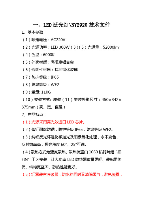
一、LED泛光灯\NY2920技术文件1、基本参数:(1)额定电压:AC220V(2)光源功率:LED 300W(3)(3)光通量:52000lm (4)色温:6000K(5)外壳材质:高硬度铝合金(6)透明件材质:特种钢化玻璃(7)防护等级:IP65(8)防腐等级:WF2(9)重量: 11KG(10)安装方式: 座装(11)安装外形尺寸:450×342×375mm (高、宽、直径)2、产品特点:(1)光源采用高光效进口LED芯片。
(2)整灯耐腐防锈,防护等级IP65,防腐等级WF2。
(3)纯铝反光杯经化学抛光及阳极氧化处理,永不变色,反射效率高,投光角度60°、25°可选。
(4)散热方式为液变散热。
散热装置由1060铝鳍片经“扣FIN”工艺安装,让大功率LED散热器重量更轻、装配更简便、结构更坚固、散热性能更好。
(5)灯罩装有呼吸器,防水的同时又清除雾气,避免凝露,延长使用寿命。
(6)安装支架角度可调:13个支架调节点,灯具更稳固;可在216°内调节照射角度。
(7)模组式拼装设计,维护更方便快捷。
3、配光曲线4、现场安装二、LED投光灯\GDL9330-200技术文件1、基本参数:(1)额定电压:AC220V(2)光源功率:LED 200W(3)(3)光通量:52000lm (4)色温:6000K(5)外壳材质:高硬度铝合金(6)透明件材质:特种钢化玻璃(7)防护等级:IP65(8)防腐等级:WF2(9)重量: 11KG(10)安装方式: 座装(11)安装外形尺寸:450×342×375mm (高、宽、直径)2、产品特点:(1)光源采用高光效进口LED芯片。
(2)整灯耐腐防锈,防护等级IP65,防腐等级WF2。
(3)纯铝反光杯经化学抛光及阳极氧化处理,永不变色,反射效率高,投光角度60°、25°可选。
(4)散热方式为液变散热。
光通量ies测试报告

光通量ies测试报告篇一:140204 修改IES数据我们上次在“更改光色”的课程〔140121期〕学习了在DIALux里修改灯具中的光源光通量。
那么,能不能直接改IES的光通量呢?下面是一位同学修改IES里的光通量之后,DIALux中显示就不精确了??灯具效率732% 〔此处应有一个抓狂的表情〕 ?我的回答见下列图 ?原则上,我们是不能随便修改IES数据的,除非在非常有信念的状况下。
哪些是有“信念”的状况?请详见140121期的课后问答哦。
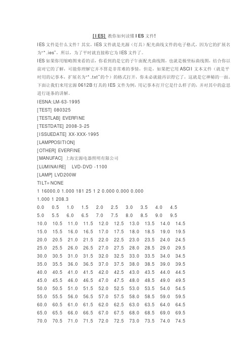
这时,应当怎么改才对呢?我们先看看IES文件里面有啥?用记事本打开一个IES文件,我们见到许多“密码”:留意TILT下面那一行数字,我们解读前三个:1、3500、1。
他们的含义分别是光源数光通量乘数如今你想给这个灯具换个大点瓦数的光源,假如只把3500修改成7000的话,放进软件计算时,照度是不会转变的哦~只是灯具效率下降了一半而已~ 应当改的是:乘数把光通量后面那个1改成2,你就会得到7000流明的光源啦!此时再放进软件去计算,照度会比原先高一倍,而灯具效率不变。
再次强调:徐工不是在教你作假哦!肯定要确认修改是符合科学的,才能改哈!篇二:LM79 801. IES LM-79 主要测试为光电性能测试,由于某些测试项目需要借助分布式光度计才能完成,所以一般的厂家没有力量做一份完好的报告,这个测试一般针对的是整灯的厂家。
主要的测试项目如下:总光通量发光效率光强分布相关色温〔CCT〕显色指数〔CRI〕色品坐标〔或称色度坐标〕输入沟通〔或直流〕电压输入沟通〔或直流〕电流输入功率〔DC或AC〕输入电压频率功率因子2.IES LM-80主要测的是LED光源的流明维持,这一测试针对的是光源厂家,所以生产灯具的厂家只需要向你们的光源厂家要这一份测试报告就好了IES LM-79:2022标准简介近期越来越多的美国买家要求LED灯具出具LM-79的测试报告,这一块也渐渐越来越受各个LED生产厂家的关注。
LED投光灯规格书
产品规格书产品名称: 10W方形投光灯产品型号: XR-TGD10W文件编号: TGD-001文件版次: A/1制订部门:技术部发行时间文件版次变更内容制订人2013-12-12 A/1文件发放部门:技术部、生产部、品管部、国内营销部、国际贸易部、工业工程部制订:审核:批准:一. 产品特点:●宽范围工作电压,长寿命,低光衰,维护成本低。
●光效高,节能省电,比传统节能灯省电75%以上。
●可直接替换传统大功率钠灯。
●环保无污染,不含对环境有害的汞污染。
二. 外观尺寸:三、技术参数:(正白条纹样品灯)项目名称参数值输入电压AC100V-240V产品功率12W±10%光源功率10W±10%灯珠类型COB光通量950lm±15%光效值* 90m/W±10%色温6500K显色指数≥70功率因数≥0.9灯珠数量1PCS(10串1并)工作环境温度-20℃~~+55℃工作环境湿度≤85%产品寿命≥25000H产品外壳材质压铸铝耐压要求1500V/5mA/3s四、光通量测试图:五、光强分布图:六、平均照度图:七、包装方式:包装名称包装规格(mm) 每盒/箱分布总数产品净重/毛重(Kg)内包装箱120*95*95 每盒数量1PCS 1PCS 每个净重0.495外包装箱675*300*270mm 每箱共装2层36PCS 每箱毛重19.3八、应用范围:户外照明九、安装说明1、配置必须由专业人员安装。
2、接线时必须切断外部电源。
3、接线时外部电源线的线芯不得外露。
注意:所有信息如有改动恕不另作通知。
如有疑问,请联系供货商。
十、LED铭牌:备注:产品铭牌中的颜色根据订单规定打勾。
Microsoft Word - YW2001-10W 规格书-加水印doc-SPECI
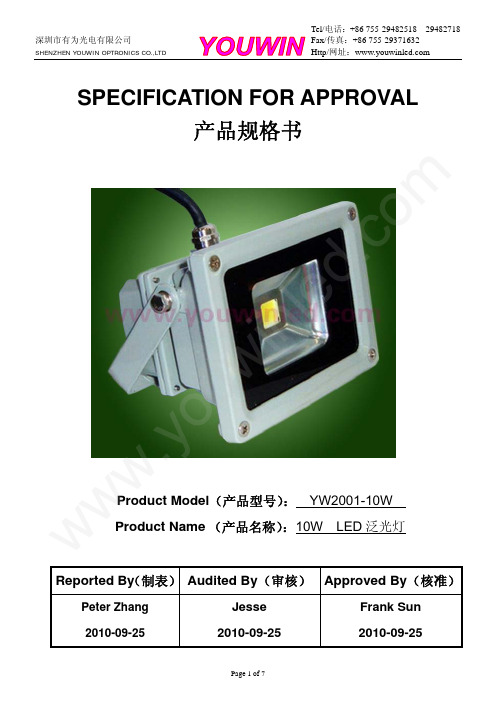
SPECIFICATION FOR APPROVAL产品规格书Product Model (产品型号): YW2001-10W Product Name (产品名称):10W LED 泛光灯Reported By (制表) Audited By (审核) Approved By (核准)Peter Zhang 2010-09-25Jesse 2010-09-25Frank Sun 2010-09-25www .y o u wi nl e d.c o mFeatures 产品描述:The light source adopts the integration of imported single high power LED, with the specialdesign of integrating many chips into one lighting source. 光源采用单颗大功率LED 集成光源,运用独特的多颗芯片集成式单模组光源设计,选用进口高亮度半导体芯片。
The crust in aluminum alloy die casting ensures the efficiency of heat emission, guaranteeingthe light a long life span.灯壳采用铝合金压铸成型,可以有效的散热并保证了光源的使用寿命。
The high pure imported aluminum from Germany as the reflector has high reflectingefficiency, and it can make sure the luminous flux, controlling the light inside of a useful area. It improves the efficiency of light uniformity and utilization, showing the LED advantage of energy saving.采用高纯度德国进口铝反射罩,有效提高了反射率,并确保了光通量输出,针对性地将LED 发出的光控制在需要范围内,提高了灯具出光效果的均匀性和光能的利用率,凸现了LED 灯具明显的节能优势。
高功率LED U-Series 10W白色SPHWHTU2NAA0数据手册说明书
Product Family Data Sheet Rev.1.4 2022.09.02Features∙Package : Ceramic package∙Dimension : 2.46 mm x 3.10 mm∙Chip Technology : Thin GaN∙ESD : 8 kV acc. to ANSI/ESDA/JEDEC JS-001 (HBM) ∙Qualifications : AEC-Q102 Qualified with RV-level 1Table of Contents1. Characteristics ----------------------- 32. Product Code Information ----------------------- 43. Typical Characteristics Graphs ----------------------- 74. Soldering Temperature Location ----------------------- 125. Mechanical Dimension ----------------------- 136. Soldering Conditions ----------------------- 147. Tape & Reel ----------------------- 158. Label Structure ----------------------- 169. Packing Structure ----------------------- 1710. Handling and Use Precautions ----------------------- 1811. Company Information ----------------------- 191. Characteristicsa) Typical Characteristics (T S = 25℃ )[1]Item Symbol Value Unit.Chromaticity Coordinate CxCyTyp. 0.32Typ. 0.33Luminous Flux (I F = 1,500 mA) ΦV Typ. 842 ㏐Forward Voltage (I F = 1,500 mA) V F Typ. 6.6 V Viewing Angle ΦTyp. 120 ºReverse Current I R Not designed for reverse operationReal Thermal Resistance (Junction to Solder point) R th_J-S (Real)Typ. 3.4K/WMax. 4.1Electrical Thermal Resistance (Junction to Solder point) R th_J-S (Elec.)Typ. 2.5K/WMax. 3.2Radiant Surface A 1.15 ㎟Note:[1] The measurement condition means that temperature dependence is excluded by applying pulse current for typically 25ms.b) Absolute Maximum RatingItem Symbol Rating UnitAmbient / OperatingTemperatureT a-40 ~ +125 ºC Storage Temperature T stg-40 ~ +125 ºC LED Junction Temperature T j150 ºC Maximum Forward current[2](T S:25℃) [3]I F1,650 ㎃Minimum Forward current[2](T S:25℃) [3]I F50 ㎃Maximum Reverse currentDo not apply for reverse currentESD Sensitivity[4]- ±8 for HBM kVNote:[2] Driving the product at forward current (IF) below Min. IF or above Max. IF may result in unpredictable behavior of the product.[3] The measurement condition means that temperature dependence is excluded by applying pulse current for typically 25㎳[4] It is included the device to protect the product from ESD.2. Product Code Information1 2 3 4 5 6 7 8 9 10 11 12 13 14 15 16 17 18S P H W H T U 2 N A A 0 A B C D E F Digit PKG Information1 2 Company name and Samsung LED PKG (SP for Samsung PKG)3 Power variant (H for automotive high power)4 5 Color variant (WH for automotive white color)6 LED PKG version (T for initial version up)7 8 Product configuration and type (U2 for automotive 2chip PKG type)9 Lens configuration (N for no lens)10 Max power (Internal code)11 Special internal code (A for automotive version)12 Specific property (0 for default)13 14 Forward voltage property15 16 CIE coordination property17 18 Luminous flux propertya) Luminous Flux Bins [5] (I F = 1,500 mA, T S= 25ºC)Symbol Flux Bin CodeFlux Range (㏐)Min MaxΦV F5 750 800 G5 800 850 H5 850 900 J5 900 950Note:[5] Luminous flux measuring equipment : CAS140CTΦV and V F tolerances are ±7% and ±0.1V, respectively.b) Voltage Bins [5] (I F = 1,500 mA, T S = 25 ºC)Symbol Voltage Bin CodeVoltage Range (V)Min Max V F2E 5.95 6.452F 6.45 6.950.310.320.330.340.350.360.290.300.310.320.330.340.350.00.10.20.30.40.50.60.70.80.900.10.20.30.40.50.60.70.8c) Color Bin [6](I F = 1,500 mA)SymbolColor Bin CodeCxCy Cx, CyS20.3190 0.3203 0.3299 0.3298 0.3430 0.3274 0.3361 0.3526 T20.31630.31450.32460.32530.31810.33300.34240.3266[6] Luminous flux measuring equipment : CAS140CTChromaticity coordinates : Cx, Cy according to CIE 1931. Cx and Cy tolerances are ±0.005, respectively.d) Luminous Flux Bins according to Color Bin (I F = 1,500 mA, T S = 25 ºC)SymbolFlux BinCodeF5G5H5Min Max Max Max Min Max 750800800850850900ΦVS2O O T2OOOT2S23. Typical Characteristics Graphsa) Spectrum Distribution (I F = 1,500 mA, T S = 25 ºC)b) Typical Chromaticity Coordinate Shift vs Forward Current (I F = 1,500 mA, T S = 25 ºC) [7]Note:[7] The measurement condition means that temperature dependence is excluded by applying pulse current for typically 25㎳0.00.20.40.60.81.01.2380430480530580630680730780R e l a t i v e I n t e n s i t yWavelength0.0000.0200.0400.060-80-60-40-2020406080C o l o r S h i f t C h a r a c t e r i s t i c sRadiation AngleΔCx ΔCyW dW d(max)λ[㎚]∆C , ∆CΦ [º]x yc) Forward Current Characteristics (T S = 25 ºC) [8]Note:[8] The measurement condition means that temperature dependence is excluded by applying pulse current for typically 25㎳0.00.30.60.91.202004006008001000120014001600R e l a t i v e L u m i n o u s F l u xForward Current0.60.70.80.91.01.102004006008001000120014001600R e l a t i v e F o r w a r d V o l t a g eForward Current-0.015-0.010-0.0050.0000.0050.0100.0150.0200.0250.03002004006008001000120014001600C o l o r S h i f t C h a r a c t e r i s t i c sForward CurrentΔCx ΔCyI v I v(1500mA)V F V F(1500mA)I F [mA]I F [mA]∆C x , ∆C yI F [mA]d) Temperature Characteristics (I F = 1,500 mA)0.60.70.80.91.01.1-40-2020406080100120140R e l a t i v e L u m i n o u s F l u xTemperature0.900.951.001.051.10-40-2020406080100120140R e l a t i v e F o r w a r d V o l t a g eTemperature-0.030-0.020-0.0100.0000.0100.0200.030-40-2020406080100120140C h r o m a t i c i t y C o o r d i n a t e S h i f tTemperatureΔCx ΔCy∆C x , ∆C yT j [℃]I v I v(25℃)T j [℃]V F V F(25℃)T j [℃]e) Derating Curve [9]Note:[9] The measurement condition means that temperature dependence is excluded by applying pulse current for typically 25㎳f) Permissible Pulse Handling Capability (I F = f(t p); D: Duty cycle)0.00.20.40.60.81.01.21.41.61.80102030405060708090100110120130140 ForwardCurrentTemperature Ts[℃]I F[A]Ts[℃]T s = 0 ~ 114 ºC Ts = 125 ºCg) Beam Angle Characteristics (I F = 1,500 mA, T S = 25 ºC)0.00.20.40.60.81.01.2-90-80-70-60-50-40-30-20-10102030405060708090R e l a t i v e L u m i n o u s F l u xRadiation AngleI v Iv(0º)Φ [º]4. Soldering Temperature LocationT j : Temperature of JunctionT S : Temperature of Solder PadR thJS : Thermal Resistance from Junction to Solder Pad5. Mechanical Dimension[Top view] [Side view] [Bottom view]Note:The dimensions in parentheses are for reference purposes.Unit: mm, Tolerance: ±0.1㎜Approximate weight : 18.0mga) Pick and PlaceDo not place pressure on the resin molded partIt is recommended to use a pick & place nozzle CN140, etc.b) Electric Schematic Diagramc) Material InformationDescription MaterialSubstrate AlN SubstratePlating AuLED Die Thin GaNPhosphor sheet Phosphor in GlassZener Diode SiliconWire AuResin Mold Silicone6. Soldering Conditionsa)Pad Configuration & Solder Pad LayoutNotes:Unit: ㎜, Tolerance : ±0.10㎜b) Reflow Conditions (Pb free)Reflow frequency: 2 times max.※ All temperatures refer to the pad of package.c) Manual Soldering Conditions***************************ºC, under soldering iron. (one time only)7. Tape & Reela) Taping Dimension※Package placement condition in a reel tapeEmpty pocket(Min. 100ea) LED mounting part Empty pocket(Min. 100ea)Notes:Unit: ㎜, LED taping quantity: 2,000ea (1Reel)b) Reel DimensionNotes: Unit: ㎜, Tolerance: ±0.2㎜F6PQC6SPHWHTU2NAA0 ABCDEFII I III I IIIIII III III II IIIIII I IIIIIII I IIIIIIIISLAA94001 / 1001 / 1,000pcsIIIIII I IIIIIII III IIII I III I III I III III IIIIIIIIABCDEFSPHWHTU2NAA0XXXXXX YYYYYY 01II I IIIIIII I IIIIIII III III II IIIIII I IIIIIII I IIIIIIII①②③④⑤⑥⑦⑧⑨/1ⓐⓑⓒ/ 1,000 pcsIIIIII I IIIIIII III IIII I III I III I III III IIIIIIa) Label StructureNote: Denoted bin code and product code above is only an example (see description on page 5)Bin Code:A, B: Forward Voltage bin (refer to page 5)C, D : Chromaticity bin (refer to page 6)E, F : Luminous Flux bin (refer to page 5)b)Lot NumberThe lot number is composed of the following characters:①②③③②③④⑤⑥⑦⑧⑨/ 1ⓐⓑⓒ/ 1,000 pcs①②: Production site (Giheung)③: Product state (A: Normal, B: Bulk, C: First Production, R: Reproduction, S: Sample)④: Year ( F: 2021, G: 2022, H: 2023…)⑤: Month (1~9, A, B, C)⑥: Day (1~9, A, B~V)⑦⑧⑨: Serial number (001 ~ 999)ⓐⓑⓒ: Product serial number (001 ~ 999)A B C D E FBin CodePart NumberLot Numbera) Packing ProcessDimension of Transportation Box in mmWidth Length Height220 245 18210. Handling and Use Precautions1)For over-current protection, we recommend the use of resistors to prevent sudden current surges caused byslight shifts in voltage2)LEDs should not be contacted to any type of fluid (i.e. water, oil, organic solvent, etc.). If cleaning is required,only use isopropyl alcohol.3)The maximum ambient temperature must be considered in order for the maximum temperature ratings not tobe exceeded.4)LEDs must be stored in a clean environment. If the LEDs are to be stored for 3 months or more after beingshipped from Samsung Electronics, they should be packed by a sealed container with nitrogen gas injected.(Shelf life of sealed bags: 12 months, temp. ~40℃, ~90% RH)5)After storage bag is open, LED subjected to soldering, solder reflow, or other high temperature processesmust be:a)Mounted within 672 hours (28 days) at an assembly line with a condition of no more than 30℃/ 60% RH.b)Stored at <10% RH.6)Repack unused products using anti-moisture packing, fold to close any openings and store in a dry place with<10% RH.7)LEDs require baking before mounting, if humidity card reading is >60% at 23±5℃.8)If baking is required, LEDs must be baked for 1 day at 60±5℃.9)LEDs are sensitive to electrostatic discharge and surges. Applying any voltage exceeding the absolutemaximum rating of the LED can cause permanent damage to the device. Damaged LEDs may have some unusual characteristics such as increased leakage current, lower turn-on voltage or may light abnormally at low current. When handling LEDs, using grounding wrist-bands or anti-static gloves is recommended.10)VOCs (volatile organic compounds) present in adhesives, flux, hardeners or organic additives, etc. that areused in luminaires may lead to discoloration of the LED when exposed to heat or light. Note that VOCs can permeate silicone bags. This phenomenon can significantly affect light output from the luminaire. To avoid this issue, please carefully evaluate materials used in your process and/or luminaire to be free of VOCs.11. Company InformationUSSamsung Semiconductor, Inc.11800 Amber park Drive #225 Alpharetta, GA 30004 USATel : +1 678 892 7385EuropeSamsung Semiconductor Europe GmbH,Einsteinstrasse 174, 81677 Munich, GermanyTel : +49 6196 66 3902JapanSamsung Japan Corporation10F, Shinagawa Grand Central Tower 2-16-4, Kounan, Minato-ku, Tokyo108-8240, JapanTel : +81 3 6369 6267China(Shenzhen)Samsung Electronics Co., Ltd.25F/26F, SCC building A, No.88, Haide Yi Road, Nanshan District,518026, Shenzhen ChinaTel : +86 21 2325 3551Copyright @1995-2022 All rights reserved Samsung Electronics LED BUSINESS1, Samsung-ro Giheung-guYongin-si, Gyeonggi-do 17113 Korea China(Shanghai)Samsung Electronics Co., Ltd.Building B, No 1065 Zhongshan RD(W), Changning District, Shanghai, ChinaTel : +86 21 2325 3504/led Sales Contact******************** ***********************IndiaSamsung ElectonicsSuite #006 Ground Floor, Copia Corporate Suites, Jasola, New Delhi 110025, India, Delhi, INDTel : +91 9600003320About Samsung Electronics Co., Ltd.Samsung inspires the world and shapes the future with transformative ideas and technologies. The company is redefining the worlds of TVs, smartphones, wearable devices, tablets, digital appliances, network systems, and memory, system LSI, foundry and LED solutions. For the latest news, please visit the Samsung Newsroom at .Copyright © 2022 Samsung Electronics Co., Ltd. All rights reserved.Samsung is a registered trademark of Samsung Electronics Co., Ltd.Specifications and designs are subject to change without notice. Non-metricweights and measurements are approximate. All data were deemed correctat time of creation. Samsung is not liable for errors or omissions. All brand, product,service names and logos are trademarks and/or registered trademarks of theirrespective owners and are hereby recognized and acknowledged.Samsung Electronics Co., Ltd.1, Samsung-roGiheung-guYongin-si, Gyeonggi-do, 17113KOREA/led。
城市LED灯光数据手册 10W-500W 黄色 CLU048-1818C4-22AL1K3说明书

DATA SHEETIntroduction Performance Characteristics Mechanical Dimensions Characteristic Curves ReliabilityPacking Specification PrecautionP 2P 3P 5P 6P 9P 10P 11 CITILED COB SeriesAmber ModelCLU048-1818C4-22AL1K31. Introduction1-1. Product Description1-2. FeaturesCITIZEN ELECTRONICS is the first COB manufacture. Our advanced knowledge and packaging technology for many years has excellent reliability and high quality of our products. CITILED COB Series covers a wide range of luminous flux from a 10W incandescent bulb to a 500W mercury lamp in general lighting sources. The element arrangement of LED package is capable of utilizing light more effectively and higher performance. The new version of CITILED COB Series succeed to reduce the thermal resistance significantly. New version creates more options to match luminaire's products design (ex. High performance , Cost effective , Higher lumen density ,Increased allowable max. If). The outline and LES size is same since version 1. 3-step MacAdam ellipse color definition at Tj=85℃ is available.・ Mechanical Dimensions :28.0×28.0×1.4 (mm)・ Package Structure :Aluminum Base Chip on Board ・ Reference Assembly :M3 screw, Connector ・ CRI (Ra):65 Typ.・ Nominal CCT :2,200K ・ Chromaticity Range :ANSI C78.377:2015.・ Thermal Resistance :0.17C/W ・ Maximum drive current :3240 mA ・ RoHS compliant・ Better die arrangement for optics・ Wide range of luminous flux and high efficacy・ Improved lumen density compared with previous version ・ UL recognized component (E358566)CLU048-1818C4-22A L1K3[1][2][3][4][5][1][2][3][4][5]Product NomenclatureCRI (Ra)CLU04818182200K Typ.65Product shape Die count in series Die count in parallel Nominal CCT2. Performance Characteristics2-1. Electro Optical Characteristics2-2. Absolute Maximum RatingsSymbol RatingPi 202.8*1If 3240*1Ir 1Top -40 ~ +100Tst -40 ~ +100Tc 105*2Tj140*3*1. Input power and forward current are the values when the LED is used within the range of the derating curve in this data sheet.*2. Refer to 3. Outline drawing for Tc measurement point.ParameterInput Power (W)Forward Current (mA)Reverse Current (mA)*3. D.C. Current : Tj = Tc + Rj-c × PiStorage Temperature (C)Case Temperature (C)Junction Temperature (C)Operating Temperature (C)( Tj=85C )R9Tc=25C*Min.Typ.Min.Min.Typ.Max Typ.Typ.Min.Typ.Max.CLU048-1818C4-22AL1K32200K-65-10,19311,583-12,6641381,62047.852.056.20.17Notes :1. Citizen Electronics maintains forward voltage +/-3%, luminous flux +/-10%,Ra and R9 +/-1.*Values of Luminous flux at Tc=25C are provided as reference only.Product codeForward Current ( mA )ThermalResistanceRj-c ( C/W )Nominal CCT Luminous flux( lm )Efficacy ( lm/W )Voltage( V )Ra T j=85CCRI2-3. Chromaticity CharacteristicsNote : Citizen Electronics maintains chromaticity ( x, y ) +/-0.0050.350.400.450.500.400.450.500.55yxx-y chart CIE19312,200KBlack Body LocusANSIANSI C78. 377:20152,200K( 0.5018, 0.4153)* The chromaticity center refers to ANSI C78.377:2015. Please refer to ANSI C78. 377 for the chromaticity center.0.52590.43420.50450.43440.47990.39670.49930.3967Color Region Nominal CCT Center Point ( x, y )ANSI parametera ( x, y )b ( x, y )c ( x, y )d ( x, y ) ( Rated current , Tj=85℃ )3. Mechanical DimensionsUnit : mmTolerances unless otherwise specified : +/-0.3・Internal Circuit18 s 18 p Protection deviceLED deviceCathodeAnodeMarking 1 : Serial No.Marking 2 : CRI CCTDies count in parallel Dies count in series CLU048H 18 18 ** **4. Characteristic Curves4-1. Forward Current Characteristics / Temperature CharacteristicsForward Current vs. Forward VoltageForward Current vs. Relative Luminous FluxTc=25C Tc=25CCase Temperature vs. Forward VoltageCase Temperature vs. Relative Luminous FluxIf=1620mAIf=1620mA48.050.052.054.056.058.060.001000200030004000V f [V ]If [mA]0%20%40%60%80%100%120%140%160%180%200%01000200030004000R e l a t i v e L u m i n o u s F l u x [a .u .]If [mA]50.051.052.053.054.055.056.00255075100V f [V ]Tc [C]0%20%40%60%80%100%120%0255075100R e l a t i v e L u m i n o u s F l u x [a .u .]Tc [C]4-2. Optical CharacteristicsSpectrumTj=85℃If=1620mA0%10%20%30%40%50%60%70%80%90%100%380430480530580630680730780R a d i a t i v e I n t e n s i t yWave length [nm]2,200KRadiation Characteristic 0%20%40%60%80%100%X Y80°70°60°50°40°30°20°10°-80°-70°-60°-50°-20°-30°-40°-10°90°-90°Case Temperaturevs. Allowable Forward Current05001000150020002500300035000255075100125I f [m A ]Tc [C]4-2. Optical Characteristics (continued)4-3. Derating Characteristics5. Reliability5-1. Reliability Test5-2. Failure Criteria-40 C × 30 minutes – 100 C × 30 minutes, 100 cycle85 C, 85 %RH for 500 hoursThermal Shock TestContinuous Operation Test High Temperature Storage TestLow Temperature Storage Test Moisture-proof Test IF=1620mA Tj=140C (with Al-fin) ×1000hrsTest Item100 C × 1000 hours -40 C × 1000 hours Test ConditionIF=1620mA Ta=25C (with Al-fin) ×1000hrs ( Tc=25C )U defines the upper limit of the specified characteristics. S defines the initial value.Note : Measurement shall be taken between 2 hours and 24 hours, and the test pieces should be return to the normal ambient conditions after the completion of each test.Total Luminous FluxΦvIf=1620mA<S × 0.85Measuring Item Symbol Measuring ConditionFailure CriteriaForward Voltage Vf If=1620mA >U × 1.11675001(2)(1)(3)Example of indication label1. TYPE e.g. CLU048-1818C4-22AL1K32. P.No. ( Cutomer's P/N )3. Lot No.e.g. 4. Quantity(1) Last two digit of the year 16 : year 2016(2) Production month 7 : JuryNote: October, November and December are designated X,Y and Z.(3) CE's control number 6. Packing Specification6-1. PackingAn empty tray is placed on top of a 6-tier tray which contain 30 pieces each.(Smallest packing unit: 180 pieces)A label with product name, quantity and lot number is placed on the upper empty tray.Tray (Dimensions: 310 x 210 x 12 mm / Materials: Electrically conductive PS)Unit : mmProduct 30 pcs/trayCUSTOMERTYPEP.NO Lot No Q'ty: CLU***-******-******* : ****** : ******* : ***--- ( 1 ) --- ( 2 ) --- ( 3 ) --- ( 4 )7. Precaution7-1. Handling with care for this product-Both the light emitting area and white rim around the light emitting area is composed of resin materials.Please avoid the resin area from being pressed, stressed, rubbed, come into contact with sharp metal nail(e.g. edge of reflector part) because the function, performance and reliability of this product are negatively impacted.-Please be aware that this product should not come into contact with any other parts while incorporating in your lightingapparatus or your other products.-Please be aware that careful handling is required after the attachment of lead wires to prevent the application of any loadto the connections.-For more information, please refer to application note "Instruction Manual(COB LED Package)".7-2. Countermeasure against static electricity-Handling of this product needs countermeasures against static electricity because this is a semiconductor product.-Please take adequate measures to prevent any static electricity being produced such as the wearing of a wristband oranti-static gloves when handling this product.-Every manufacturing facility in regard to the product (plant, equipment, machine, carrier machine and conveyance unit)should be connected to ground and please avoid the product to be electric-charged.-ESD sensitivity of this product is over 1,000V (HBM, based on JEITA ED-4701/304).-After assembling the LEDs into your final product(s), it is recommended to check whether the assembled LEDs aredamaged by static electricity (electrical leak phenomenon) or not.-It is easy to find static damaged LED dies by a light-on test with the minimum current value.7-3. Caution of product assembly-Regarding this product assembling on the heat sink, it is recommended to use M3 screw.It might be good for screw tightening on the heat sink to do temporary tightening and final tightening.In addition, please don’t press with excess stress on the product.-The condition of the product assembling on the heat sink and the control of screw tightening torque needs to be optimized according to the specification of the heat sink.-Roughness, unevenness and burr of surface negatively impact thermal bonding between the product and heat sink andincrease heat thermal resistance between them.Confidence of thermally and mechanical coupling between the product and heat sink are confirmed by checkingthe mounting surface and measuring the case temperature of the product.-In order to reduce the thermal resistance at assembly, it might be good to use TIM (Thermal Interface Material) on whole contact surface of the product.In case of using thermal grease for the TIM, it might be good to apply uniformly on the contact surface of the product.In case of using thermal sheet for the TIM, it might be good to make sure that the product is NOT strained by stress when the screws are tightened for assembly.-For more information, please refer to application note "Instruction Manual(COB LED Package)".7-4. Thermal Design-The thermal design to draw heat away from the LED junction is most critical parameter for an LED illumination system. High operating temperatures at the LED junction adversely affect the performance of LED’s light output and lifetime. Therefore the LED junction temperature should not exceed the absolute maximum rating in LED illumination system. -The LED junction temperature while operation of LED illumination system depends upon thermal resistance of internal LED package (Rj-c), outer thermal resistances of LED package, power loss and ambient temperature. Please take both of the thermal design specifications and ambient temperature conditions into consideration for the setting of driving conditions.-For more information, please refer to application note "Thermal Management", "Instruction Manual(COB LED Package)".7-5. Driving Current-A constant current is recommended as an applying driving current to this product.In the case of constant voltage driving, please connect current-limiting resistor to each products in series and control the driving current to keep under the absolute maximum rating forward current value.-Electrical transient might apply excess voltage, excess current and reverse voltage to the product(s).They also affect negative impact on the product(s) therefore please make sure that no excess voltage, no excess current and no reverse voltage is applied to the product(s) when the LED driver is turn-on and/or turn-off.-For more information, please refer to application note "Driving", "Instruction Manual(COB LED Package)".7-6. Lighting at a minimum current value-A minimum current value of lighting of all dice is 15mA.When a minimum current is applied, LED dice may look different in their brightness due to the individual difference of the LED element, and it is not a failed product.7-7. Electrical Safety-This product is designed and produced according to IEC 62031:2008(IEC 62031:2008 LED modules for general lighting. Safety specification)-Dielectric voltage withstand test has been conducted on this product to see any failure after applyingvoltage between active pads and aluminum section of the product, and to pass at least 500V.-Considering conformity assessment for IEC62031:2008, almost all items of the specification depend uponyour final product of LED illumination system.Therefore, please confirm with your final product for electrical safety of your product.As well, the products comply with the criteria of IEC62031:2008 as single LED package.- A minimum current value of lighting of all dice is 90 mA. When a minimum current is applied, LED dice may look different in their brightness due tothe individual difference of the LED element, and it is not a failed product.7-8. Recommended soldering Condition (This product is not adaptable to reflow process.) -For manual solderingPlease use lead-free soldering.Soldering shall be implemented using a soldering bit at a temperature lower than 350C, and shall befinished within 3.5 seconds for one land.No external force shall be applied to resin part while soldering is implemented.Next process of soldering should be carried out after the product has return to ambient temperature.Contacts number of soldering bit should be within twice for each terminal.* Citizen Electronics cannot guarantee if usage exceeds these recommended conditions.Please use it after sufficient verification is carried out on your own risk if absolutely necessary.-For more information, please refer to application note "Instruction Manual(COB LED Package)".7-9. Eye Safety-The International Electrical Commission (IEC) published in 2006 IEC 62471”2006 Photobiological safety of lamps and lamp systems ” which includes LEDs within its scope.When sorting single LEDs according to IEC 62471, almost all white LEDs can be classifiedas belonging to either Exempt Group (no hazard) or Risk Group 1 (low risk).-However, Optical characteristics of LEDs such as radiant flux, spectrum and light distribution are factorsthat affect the risk group determination of the LED, and especially a high-power LED, that emits lightcontaining blue wavelengths,might have properties equivalent to those of Risk Group 2 (moderate risk).-Great care should be taken when directly viewing an LED that is driven at high current, has multipleuses as a module or when focusing the light with optical instruments, as these actions might greatlyincrease the hazard to your eyes.-It is recommended to regard the evaluation of stand-alone LED packages as a referenceand to evaluate your final product.7-10. This product is not designed for usage under the following conditions.If the product might be used under the following conditions, you shall evaluate its effect and appropriate them. In places where the product might:-directly and indirectly get wet due to rain and/or at place with the fear.-be damage by seawater and/or at place with the fear-be exposed to corrosive gas (such as Cl2, H2S, NH3, SOx, NOx and so on) and/or at place with the fear.-be exposed to dust, fluid or oil and/or at place with the fear.Precautions with regard to product use(1) This document is provided for reference purposes only so that CITIZEN ELECTRONICS' products are used as intended. CITIZEN ELECTRONICS neither makes warranties or representations with respect to the accuracy or completeness of the information contained in this document nor grants any license to any intellectual property rights or any other rights of CITIZEN ELECTRONICS or any third party with respect to the information in this document. (2) All information included in this document such as product data, diagrams, charts, is current as of the date this document is issued.Such information, however, is subject to change without any prior notice.Before purchasing or using any CITIZEN ELECTRONICS' products listed in this document, please confirm the latest product information with a CITIZEN ELECTRONICS' sales office, and formal specifications must be exchanged and signed by both parties prior to mass production.(3) CITIZEN ELECTRONICS has used reasonable care in compiling the information included in this document, but CITIZEN ELECTRONICS assumes no liability whatsoever for any damages incurred as a result of errors or omissions in the information included in this document.(4) Absent a written signed agreement, except as provided in the relevant terms and conditions of sale for product, and to the maximum extent allowable by law, CITIZEN ELECTRONICS assumes no liability whatsoever, including without limitation, indirect, consequential, special, or incidental damages or loss, including without limitation, loss of profits, loss of opportunities, business interruption and loss of data, and disclaims any and all express or implied warranties and conditions related to sale, use of product, or information, including warranties or conditions of merchantability, fitness fora particular purpose, accuracy of information, or no infringement.(5) Though CITIZEN ELECTRONICS works continually to improve products' quality and reliability, products can malfunction or fail. Customers are responsible for complying with safety standards and for providing adequate designs and safeguards to minimize risk and avoid situations in which a malfunction or failure of a product could cause loss of human life, bodily injury or damage to property, including data loss or corruption.In addition, customers are also responsible for determining the appropriateness of use of any information contained in this document such as application cases not only with evaluating by their own but also by the entire system.CITIZEN ELECTRONICS assumes no liability for customers' product design or applications.(6) Please contact CITIZEN ELECTRONICS' sales office if you have any questions regarding the information contained in this document, or if you have any other inquiries.CITIZEN Micro HumanTech is a registered trademark of Citizen Holding Co., Japan.CITILED is a registered trademark of CITIZEN ELECTRONICS CO., LTD. Japanand are trademarks or registered trademarks of CITIZEN HOLDINGS CO., LTD. JAPAN.is a trademark or a registered trademark of CITIZEN ELECTRONICS CO., LTD. JAPAN.。
超高亮度10W白光LED
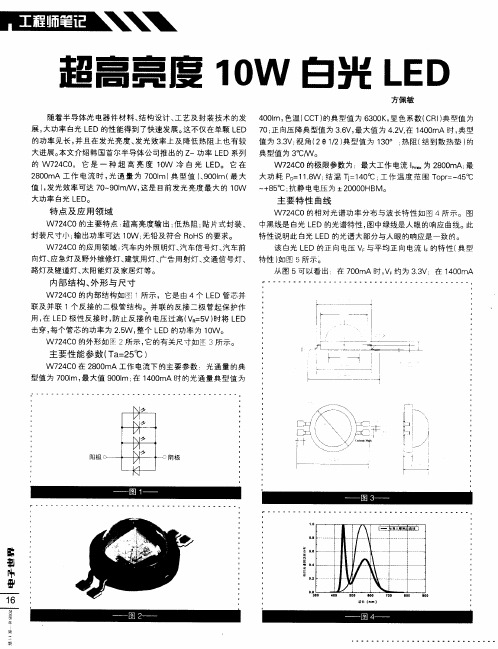
值 )发光效率可达 7 ~ 0m/ , , 0 9 1 W 这是 目前发光亮度最 大的 1 W 0
大功 率 白光 L D。 E
~
主 要特性 曲线
W7 4 0的相对光谱功率分布与波长特 性如 图 4所示。图 2C
特 性 说 明 此 白光 L D 的 光谱 大 部 分与 人 眼 的 响应 是 一致 的 。 E 该 白光 L D 的正 向 电压 V 与 平 均正 向 电流 l E 的特 性 ( 型 典
n T — } 一
主要性能 参数 ( a 2 ℃ ) T=5
W 7 4 0在 2 0 mA工 作 电流 下 的主 要 参 数 :光 通 量 的典 2C 80
型值 为 7 0m , 大值 9 0m; 1 0 mA 时 的 光 通 量 典 型 值 为 01 最 01 在 40
’。
特点及 应用领 域
封装尺寸小 ; 出功率可达 1W ; 输 无铅及符合 R H 0 o S的要求。
W 7 4 0的应 用 领域 : 2C 汽车 内外 照 明灯 、 汽车 信 号 灯 、 车前 汽
W7 4 0的主要特 点 . 2C 超高亮度输 出; 热阻 : 低 贴片式封装 、 中黑线是 白光 L D的光谱特性 , E 图中绿线是人眼的响应曲线。此
/l
I1 /
\
\\
WHELEN L10 Super-LED Beacon 设装文件说明书

©2011 Whelen Engineering Company Inc.Form No.14506B (061214)A u t o m o t i v e : Installation Guide:L10 Super-LED® Beacon(12 and 24 volt)Models L10H**, L10H**4, L10L** and L10L**4For warranty information regarding this product, visit /warrantyWarnings to InstallersWhelen’s emergency vehicle warning devices must be properly mounted and wired in order to be effective and safe. Read and follow all of Whelen’s written instructions when installing or using this device. Emergency vehicles are often operated under high speed stressful conditions which must be accounted for when installing all emergency warning devices. Controls should be placed within convenient reach of the operator so that they can operate the system without taking their eyes off the roadway. Emergency warning devices can require high electrical voltages and/or currents. Properly protect and use caution around live electrical connections.Grounding or shorting of electrical connections can cause high current arcing, which can cause personal injury and/or vehicle damage, including fire. Many electronic devices used in emergency vehicles can create or be affected by electromagnetic interference. Therefore, after installation of any electronic device it is necessary to test all electronic equipment simultaneously to insure that they operate free of interference from other components within the vehicle. Never power emergency warning equipment from the same circuit or share the same grounding circuit with radio communication equipment. All devices should be mounted in accordance with the manufacturer’s instructions and securely fastened to vehicle elements of sufficient strength to withstand the forces applied to the device. Driver and/or passenger air bags (SRS) will affect the way equipment should be mounted. This device should be mounted by permanent installation and within the zones specified by the vehicle manufacturer, if any. Any device mounted in the deployment area of an air bag will damage or reduce the effectiveness of the air bag and may damage or dislodge the device. Installer must be sure that this device, its mounting hardware and electrical supply wiring does not interfere with the air bag or the SRS wiring or sensors. Mounting the unit inside the vehicle by a method other than permanent installation is not recommended as unit may become dislodged during swerving; sudden braking or collision. Failure to follow instructions can result in personal injury. Whelen assumes no liability for any loss resulting from the use of this warning device. PROPER INSTALLATION COMBINED WITH OPERATOR TRAINING IN THE PROPER USE OF EMERGENCY WARNING DEVICES IS ESSENTIAL TO INSURE THE SAFETY OF EMERGENCY PERSONNEL AND THE PUBLIC.Warnings to UsersWhelen’s emergency vehicle warning devices are intended to alert other operators and pedestrians to the presence and operation of emergency vehicles and personnel. However, the use of this or any other Whelen emergency warning device does not guarantee that you will have the right-of-way or that other drivers and pedestrians will properly heed an emergency warning signal. Never assume you have the right-of-way. It is your responsibility to proceed safely before entering an intersection, driving against traffic, responding at a high rate of speed, or walking on or around traffic lanes. Emergency vehicle warning devices should be tested on a daily basis to ensure that they operate properly. When in actual use, the operator must ensure that both visual and audible warnings are not blocked by vehicle components (i.e.: open trunks or compartment doors), people, vehicles, or other obstructions. It is the user’s responsibility to understand and obey all laws regarding emergency warning devices. The user should be familiar with all applicable laws and regulations prior to the use of any emergency vehicle warning device. Whelen’s audible warning devices are designed to project sound in a forward direction away from the vehicle occupants. However, because sustained periodic exposure to loud sounds can cause hearing loss, all audible warning devices should be installed and operated in accordance with the standards established by the National Fire Protection Association.Safety FirstThis document provides all the necessary information to allow your Whelen product to be properly and safely installed. Before beginning the installation and/or operation of your new product, the installation technician and operator must read this manual completely. Important information is contained herein that could prevent serious injury or damage.WARNING: This product can expose you to chemicals including Methylene Chloride which is known to the State of California to cause cancer, and Bisphenol A, which is known to the State of California to cause birth defects or other reproductive harm. For more information go to .•Proper installation of this product requires the installer to have a good understanding of automotive electronics, systems and procedures.•Whelen Engineering requires the use of waterproof butt splices and/or connectors if that connector could be exposed to moisture.•Any holes, either created or utilized by this product, should be made both air- and watertight using a sealant recommended by your vehicle manufacturer.•Failure to use specified installation parts and/or hardware will void the product warranty.•If mounting this product requires drilling holes, the installer MUST be sure that no vehicle components or other vital parts could be damaged by the drilling process. Check both sides of the mounting surface before drilling begins. Also de-burr the holes and remove any metal shards or remnants. Install grommets into all wire passage holes.•If this manual states that this product may be mounted with suction cups, magnets, tape or Velcro®, clean the mounting surface with a 50/50 mix of isopropyl alcohol and water and dry thoroughly.•Do not install this product or route any wires in the deployment area of your air bag. Equipment mounted or located in the air bag deployment area will damage or reduce the effectiveness of the air bag, or become a projectile that could cause serious personal injury or death. Refer to your vehicle owner’s manual for the air bag deployment area. The User/Installer assumes full responsibility to determine proper mounting location, based on providing ultimate safety to all passengers inside the vehicle.•For this product to operate at optimum efficiency, a good electrical connection to chassis ground must be made. The recommendedprocedure requires the product ground wire to be connected directly to the NEGATIVE (-) battery post (this does not include products that use cigar power cords).•If this product uses a remote device for activation or control, make sure that this device is located in an area that allows both the vehicle and the device to be operated safely in any driving condition.•Do not attempt to activate or control this device in a hazardous driving situation.•This product contains either strobe light(s), halogen light(s), high-intensity LEDs or a combination of these lights. Do not stare directly into these lights. Momentary blindness and/or eye damage could result.•Use only soap and water to clean the outer lens. Use of other chemicals could result in premature lens cracking (crazing) and discoloration. Lenses in this condition have significantly reduced effectiveness and should be replaced immediately. Inspect and operate this product regularly to confirm its proper operation and mounting condition. Do not use a pressure washer to clean this product.•It is recommended that these instructions be stored in a safe place and referred to when performing maintenance and/or reinstallation of this product.•FAILURE TO FOLLOW THESE SAFETY PRECAUTIONS AND INSTRUCTIONS COULD RESULT IN DAMAGE TO THE PRODUCT OR VEHICLE AND/OR SERIOUS INJURY TO YOU AND YOUR PASSENGERS!51 Winthrop RoadChester, Connecticut 06412-0684Phone: (860) 526-9504Internet: Salese-mail:*******************CustomerServicee-mail:*******************®ENGINEERING COMPANY INC.Specifications:12VInput Voltage . . . . . . . . . . . . . . . . . . . . . . . . . . . . . 12.8 VDC +/- 20%Input Current / Peak . . . . . . . . . . . . . . . . . . . . . . . . . . . . . . . .1 AMP Input Current / Avg . . . . . . . . . . . . . . . . . . . . . . . . . . . . . . .0.4 AMPS 24VInput Voltage . . . . . . . . . . . . . . . . . . . . . . . . . . . . . 25.6 VDC +/- 20%Input Current / Peak . . . . . . . . . . . . . . . . . . . . . . . . . . . . . .0.5 AMPS Input Current / Avg . . . . . . . . . . . . . . . . . . . . . . . . . . . . . . .0.2 AMPSPermanent Mount:1.Using the base as a template, mark the 3mounting holes onto the mounting surface. Remove the base and mark the location of the wire access hole,centered between the 3 mountingholes.2.Drill the mounting holes using a drill bit sized for a #10screw. Drill a wireaccess hole using a3/8” drill bit. Removethe burrs from thewire access hole so as not to damage the wires. It is recommended that a rubber grommet be installed to further protect the wires. A gasket will be used between the beacon base and the mounting surface.3.After connecting the beacon to the power cable, feed the wires through the cable access hole and place the base and gasket on the mounting surface. Align the mounting holes in the base with the mounting holes in the mounting surface. Secure beacon firmly to the mounting surface using the #10 X 5/8 Sheet Metal Screws provided.1 Inch (NPT) Pipe Mount:Threading for a 1” NPT pipe mounting is precast into the base. Feed the power cable through the 1 “ pipe and connect to wires of beacon.Screw the beacon to the threads on the pipe, taking precaution not to damage the power wires. NOTE: Do not tighten the base too hard so as not to damage the threads.Temporary Mount (Magnetic, Suction Cup, etc.)With the magnetic or magnetic/suction cup mounting options you will be able to mount your beacon so that you can remove it if necessary and avoid drilling.Magnetic/suction: Thoroughly clean the proposed mounting surface prior to mounting. For suction cup mounting, wipe the suction cup clean, place the beacon onto its mounting surface and apply gentle pressure to ensure a good seal has been achieved. The Magnetic/Suction Cups mount the same way as standard suction cups but are best suited to a flat, steel surface.Magnetic: Place the beacon onto the mounting surface and plug it into the vehicle cigar lighter.Wiring:WARNING! All customer supplied wires that connect to the positive terminal of the battery must be sized to supply at least 125% of the maximum operating current and FUSED at the battery to carry the load. DO NOT USE CIRCUIT BREAKERS WITH THIS PRODUCT!This product is polarity sensitive. If the positive and negative wires are reversed the unit will not function. Fuse the positive (RED) wire @ 3Amps at the battery.1.Connect the RED wire to positive voltage (+VBAT). A customersupplied single pole/single throw (SPST) switch may be used to control the ON/OFF function of the beacon.2.Connect the BLK or BLK/WHT wire to chassis ground.Operation:Scan-Lock™ (White/Violet):To use Scan-Lock™, the beacon must be turned on:TO CHANGE PATTERNS: To cycle forward to the next available pat-tern apply +VBAT to the WHT/VIO wire for less than 1 second and release. To cycle back to the previous pattern apply +VBAT to the WHT/VIO wire for more than 1 second and release.TO CHANGE THE DEFAULT PATTERN: When the desired pattern is displayed, allow it to run for more than 5 seconds. The beacon will now display this pattern when initially activated.TO RESTORE THE FACTORY DEFAULT PATTERN: With the power to the beacon off, apply +VBAT to the WHT/VIO wire. Turn power to the beacon on. The factory default pattern should now be displayed.A normally open momentary switch can be used to control Scan-Lock™ operation.Flash Patterns:IMPORTANT: It is the responsibility of the installation technician to make sure that the installation and operation of this product will not interfere with or compromise the operation or efficiency of any vehicle equipment! Permanent mounting of this product will require drilling. It is absolutely necessary to make sure that no other vehicle components could be damaged by this process.Check both sides of the mounting surface before starting. If damage is likely, select a different mounting location.1.SignalAlert™ 75etFlash® 753.DoubleFlash 754.SingleFlash 75Alert™ 756.LongBurst™ 757.PingPong™ 758.SingleFlash 609.SingleFlash 9010.SingleFlash 12011.SingleFlash 30012.DoubleFlash 150Alert™ 15014.ActionFlash™ 5015.ActionFlash 15016.ModuFlash™17.ActionScan™18.Steady。
10~180W泛光灯规格书
5年电 费 (人 民币1.0元/度) 10公 里路 灯500盏 5年电 费 (人 民币1.0元/度) 5年寿 命 期换 灯 费用 含 工资 (375元/盏) 5年寿 命 期总 费 用 电 费+维护 费 (1.0元/度) 以LED路 灯取 代 现有 的 灯源 可 节约 电 费及 更 换成 本 (元) 每 一盏 节 省费 用 (元) 说 明: 计 算 过 程 中 尚 未 考 虑 传 统 钠 灯 更 换,维 修 等 方 面 费 用 。
3000/6000K
82-85lm/W
120
502)
20pcs/Cree
DC24V A C 11 0 V /2 2 0 V
3000/6000K
82-85lm/W
120
602)
24pcs/CreeFra bibliotekDC24V A C 11 0 V /2 2 0 V
3000/6000K
82-85lm/W
120
702)
28pcs/Cree
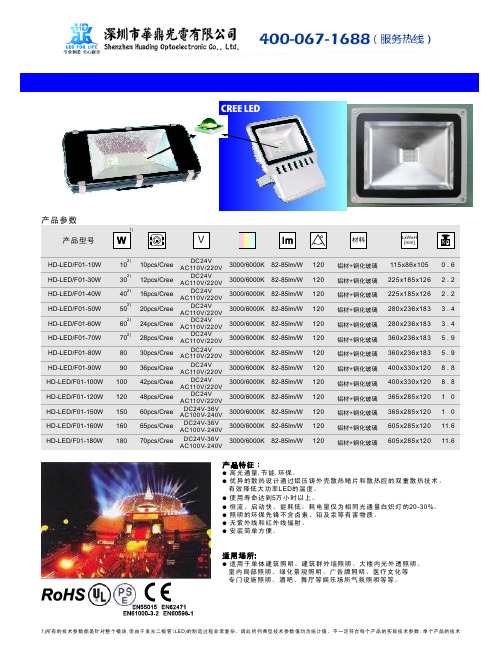
0.6 2.2 2.2 3.4 3.4 5.9 5.9 8.8 8.8 10 10 11.6 11.6
● 高光 通量,节 能,环 保。 ● 优异的散热设计通过铝压铸外壳散热鳍片和散热腔的双重散热技术,
有 效 降低 大 功率LED的 温 度。 ● 使用 寿命 达 到5万小 时 以上 。 ● 恒流 、启 动 快、 能 耗低 , 耗电 量 仅为 相 同光 通 量白 炽 灯的20-30%。 ● 照明的环保先锋不含卤素、铅及汞等有害物质。 ● 无紫外线和红外线辐射。 ● 安装简单方便。
DC24V A C 11 0 V /2 2 0 V
3000/6000K
82-85lm/W
10W大功率LED说明书
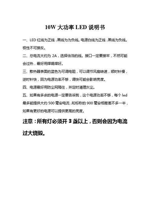
10W大功率LED说明书
一、LED红线为正线,黑线为为负线。
电源白线为正线,黑线为负线。
极性不可接反。
二、总电流大约为2A,选择恰当的线。
接口一定要接牢,不然可能会过热,最好用焊锡焊好。
三、散热器表面的蓝色为可调电阻,可以调节风扇转速,顺时针慢,逆时针快,因为电源功率不够,调快可能会影响亮度。
四、电源最好用防尘网隔住,并定时清理灰尘。
五、如果有多余的电源一定要告诉我,这个电源功率不够,每个led 最多能提供大约500毫安电流,和标称的900毫安相差差不多一半,如果有更好的电源可以提供更高的亮度。
注意:所有灯必须开3盏以上,否则会因为电流过大烧毁。
读懂IES文件---绝对经典,光电行业必读
德协管理 LED泛光灯 产品说明书
文件标识码: LED-QAS-100-0.2日期日期:: 4月18日, 2015版本 - 2 页码1 / 16起书人 (SC&COE):Sam Leung / Leslie He /J.M. Díez (17/04/2014)SC&COE´s 审批人审批人::José M. Díez (28/02/2015)客户:客户审批客户审批::目录:1. 目标范围 ..…………………………………………………………………………………………. 2页2. LED 泛光灯的基本描述a. LED 泛光灯 220V 50Hz ………………………………………………………………...… 2页b. LED 泛光灯带支架和可充锂电池……………………………………………………….... 3页3. LED 泛光灯图示 …………………………………………………………………………………...... 4页4. 所需的的认证检测标准 …………………………………………………………………………. 5页5. LED 泛光灯的基础原理a. LED 泛光灯电路和技术参数 …………………………………………………………….. 5页b. LED 泛光灯主结构(部分术语表.) …………………………………………………… 7 页6. 质量标准的基本要求.避免故障和避免意料外寿命短的建议…………………………………………………………… 7页7. 零部件的质量标准 …………………………………………………………………………………. 8 页8. 生产组装过程中的质量标准在生产过程中的质量要求…………………………………………………………………………… 11 页9. LED 泛光灯装配并避免重大缺陷 ……………………………………………………………….. 14 页10. 质量控制管理 ………………………………………………………………………………………. 15 页11. 通过SC&COE 质量检验的要求 ………………………………………………………………. 16页文件标识码: LED-QAS-100-0.2日期日期:: 4月18日, 2015版本 - 2 页码2 / 16起书人 (SC&COE):Sam Leung / Leslie He /J.M. Díez (17/04/2014)SC&COE´s 审批人审批人::José M. Díez (28/02/2015)客户:客户审批客户审批::1. 目标范围目标范围::本标准目的是为LED 灯的供应商和/或制造商提供一个质量方针,包括能更好地保证,给我们的客户提供符合质量要求的产品,在装运前会由SC & COE 检验与控制产品质量(PSQCI ),提出避免交付失败或客户拒绝收货,避免影响最终交货的准时性,从而使各方有额外的成本支出的要求和建议。
灯光设计IES文件的制作和修改
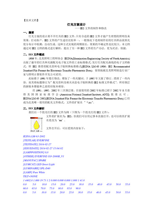
【技术文档】灯光方案设计——IES文件的制作和修改一、摘要灯光方案的设计离不开灯具的IES文件,只有合适的IES文件才能产生理想的照明仿真效果,打动客户。
IES文件的产生途径比较单一:一般情况下是将制作好的灯具样品放到光度分布计中检测,自动生成。
这种方式实现的周期很长,效果的不确定性也比较大。
本文档通过对IES文档的格式进行解析,提出了另一种IES文件的生产办法,更为灵活、快捷。
二、IES文件概述1986年,北美照明工程师协会IESNA(Illumination Engineering Society of North America)出版了最早的灯具和光源配光电子版文件的工业标准格式,发行灯具配光曲线的电子文档格式,即IES推荐的配光资料电子版转换标准格式(IESNA LM-63-1986:IES Recommended Standard File Format for Electronic Transfer Photometric Data),很快地被北美照明制造行业厂家与照明计算软件开发公司采用。
此标准于1991年進行修改,增加了一些关键词。
于1995年又做了修订,澄清了一些內容,而其将标题修订为”配光资料及相关讯息电子版转换的IES标准文件格式”,所有修訂的新版本都能和之前的旧版本相容。
经1991、1995、2002年三次修訂後。
目前使用的2002年标准已經于2002年8月获得美国国家标准学会(American National Standard Institute, ANSI)批准认可,IESNA LM-63-2002(IESNA Standard File Format for Electronic Transfer Photometric Data)已经成为北美唯一使用的配光文件格式,文件的扩展名”*.ies”。
三、IES文件解析我们以一个投光灯的IES文件为例(下图为一个投光灯的IES文件):文件的扩展名为:IES;但我们可以用记事本直接打开,也可以将其扩展名更改为’txt’。
LED泛光灯(投光灯)规格书(10W)

SPECIFICATION(产品规格书)R&D DEPARTMENT(技术部)★产品介绍:大功率 LED 泛光灯,外形独特,精简,代表性强,将现代建筑与灯具巧妙的结合,极具观赏价值。
★应用领域:适用于厂区,体育馆,码头,广告牌,建筑物,草坪,园艺设计亮化工程等投光和装饰照明所需要的场所。
★产品特性:✧光学配光,无眩光,无光染,方向性强,均匀度高。
✧大功率LED 芯片集成封装10W。
✧恒压恒流驱动,稳定的整流,恒压恒流驱动电源,瞬时启动,0.95以上功率因素,电源效率高,安全可靠。
✧灯具外壳最佳一体化的散热功能,外观设计大方新颖。
✧反光罩表面阳极氧化,与光源紧密贴合“一体“,出光效率高。
✧表面处理:静电喷塑耐高温,耐气候性好,色彩丰富。
✧灯体,高压压铸铝,结构紧凑,牢固耐腐蚀。
✧可靠硅橡胶密封,耐150 度以上高温,不老化,灯体密封性好,防水防尘。
✧发光色彩丰富,具有红、绿、蓝、黄、白等多种颜色。
★主要技术参数:★使用说明输入电压Input voltage AC85V-265V 产品图片Picture电源频率Freqency range50HZ-60HZ总谐波失真Tatal harmonic distortion ≤9% 功率因素Power factor>0.98 LED 工作电压Working voltage DC30-36V LED 数量 LED quantity 1PC LED 功耗LED consumption 10W 系统总功耗System consumption 11.5W LED 发光效率 LED luminous efficiency 90-100LM/W LED 初始光通量 LED luminous暖白Warm white 1700LM 尺寸参数图Dimension 正白Pure white 1920LM冷白Cold white 1872LM灯具效率 Lamp's efficiency >95%平均照度Average illuminance 高度(height)为 1M >71LUX 高度(height)为 2M >20LUX 高度(height)为 3M >10.2LUX 光斑面积 Illuminance area高度(height)为 1M 3.3 *3.3M 高度(height)为 2M 6.5*6.5M 高度(height)为 3M 9.8*9.8M 照度均匀度Illuminance uniformity >0.68相关色温Color temperature 暖白Warm white 2700-3500K 正白Pure white 5500-6500K 冷白Cold white 7000-10000K 显色指数Color rendering index 暖白WW Ra >78 正/冷白PW/CW Ra >85 配光曲线Light distribution 对称式/矩形光斑 配光方式 Light designLED+反光罩二次配光 LED 结点温升Junction temperature ≤60℃工作环境温度Working temperature -30℃——+55℃ 储藏环境温度Storage temperature -25℃——+65℃ 防护等级IP GradeIP65 配光曲线Light distribution光源使用寿命Working life-span >50,000H电源连接线 Connect wire棕色Brown L 火线 蓝色Blue N 零线 黄绿Yellow/Green G地线 灯头外壳颜色Color of lamp shell 银色或黑色Silver or Black认证,证书Certificate CE, RoHS 光束角Beam angle120度 产品净重/毛重Lamp weight : G.W./N.W. 0.6Kg/0.8Kg 包装尺寸(CM )Lamp packing dimension13*10*11CM1. 产品使用工作电压:AC 85V~265V 50/60Hz,请勿超出工作电压范围。
LED投光灯光度数据IES文件

β-25.0
β-20.0
β-15.0
β-10.0
β-5.0 0.02 0.03 0.09 0.21 0.33 0.42 0.51 0.62
β10.0 0.02 0.03 0.09 0.21 0.33 0.41 0.50 0.60
β15.0
β20.0
β25.0
0.02 0.03 0.06 0.14 0.24 0.32 0.39 0.47
0.02 0.03 0.07 0.16 0.27 0.36 0.43 0.52
0.02 0.03 0.08 0.18 0.30 0.38 0.46 0.56
0.02 0.03 0.09 0.20 0.32 0.40 0.49 0.59
0.02 0.03 0.09 0.21 0.33 0.41 0.50 0.61
IES Report---投光灯 光度数据文件:SE20-15-A-W.IES 区域光通量表 - (续)
β-30.0 B-50.0 B-45.0 B-40.0 B-35.0 B-30.0 B-25.0 B-20.0 B-15.0 B-10.0 B-5.0 B0.0 B5.0 B10.0 B15.0 B20.0 B25.0 B30.0 B35.0 B40.0 B45.0 B50.0 B55.0 B60.0 B65.0 B70.0 B75.0 B80.0 B85.0 B90.0 Total β-25.0 β-20.0 β-15.0 β-10.0 β-5.0 0.75 0.95 1.35 1.85 2.89 5.41 9.88 18.70 49.52 94.24 101.47 63.57 24.60 12.26 7.00 3.78 2.10 1.49 1.08 0.83 0.67 0.55 0.45 0.36 0.26 0.13 0.05 0.03 2.91 β0.0 0.74 0.95 1.34 1.83 2.86 5.33 9.74 18.29 47.51 89.97 102.02 63.50 24.46 12.30 7.01 3.80 2.10 1.49 1.08 0.83 0.67 0.55 0.45 0.35 0.25 0.13 0.05 0.03 3.31 β5.0 β10.0 0.73 0.92 1.28 1.75 2.63 4.72 8.27 13.92 26.51 52.09 59.08 36.99 18.03 10.51 6.22 3.43 2.03 1.47 1.05 0.82 0.66 0.54 0.44 0.35 0.25 0.12 0.05 0.03 3.81 β15.0 β20.0 β25.0 β30.0 0.55 0.65 0.77 0.96 1.26 1.58 1.94 2.42 2.98 3.39 3.44 3.12 2.61 2.11 1.73 1.41 1.09 0.84 0.70 0.59 0.50 0.41 0.34 0.27 0.18 0.09 0.04 0.03 1.41 β30.0 B-90.0 B-85.0 B-80.0 B-75.0 B-70.0 B-65.0 B-60.0 B-55.0 B-50.0 B-45.0 B-40.0 B-35.0 B-30.0 B-25.0 B-20.0 B-15.0 B-10.0 0.61 0.73 0.90 1.22 1.59 2.08 2.95 4.24 5.49 6.35 6.46 5.77 4.61 3.34 2.37 1.78 1.38 1.01 0.79 0.66 0.55 0.46 0.38 0.30 0.20 0.10 0.04 0.03 1.66 0.67 0.81 1.06 1.46 1.95 2.90 4.70 6.88 9.22 11.12 11.40 9.89 7.65 5.38 3.43 2.22 1.62 1.20 0.89 0.72 0.60 0.49 0.40 0.32 0.22 0.11 0.04 0.03 1.94 0.71 0.88 1.21 1.65 2.35 4.00 6.67 10.27 15.48 21.90 23.17 17.55 11.90 7.84 4.85 2.79 1.84 1.36 0.98 0.77 0.63 0.52 0.42 0.34 0.24 0.12 0.04 0.03 2.23 0.73 0.93 1.31 1.79 2.72 4.94 8.62 14.69 29.23 56.89 61.97 38.14 18.05 10.40 6.18 3.40 2.01 1.46 1.05 0.81 0.66 0.54 0.44 0.35 0.25 0.12 0.05 0.03 2.56 0.69 0.86 1.17 1.59 2.24 3.71 6.21 9.56 14.39 20.12 21.65 17.19 12.05 7.96 4.91 2.84 1.87 1.38 0.99 0.78 0.64 0.53 0.43 0.34 0.24 0.12 0.04 0.03 4.46 0.65 0.79 1.02 1.39 1.84 2.68 4.24 6.32 8.60 10.47 10.92 9.69 7.62 5.44 3.51 2.27 1.66 1.22 0.90 0.74 0.61 0.50 0.41 0.32 0.22 0.11 0.04 0.03 5.17 0.59 0.70 0.86 1.14 1.49 1.93 2.71 3.84 5.00 5.83 6.02 5.51 4.52 3.36 2.42 1.83 1.41 1.03 0.81 0.67 0.56 0.46 0.38 0.29 0.20 0.10 0.04 0.03 5.96 0.53 0.62 0.73 0.90 1.17 1.47 1.82 2.26 2.76 3.13 3.22 2.99 2.57 2.12 1.76 1.45 1.11 0.86 0.72 0.61 0.51 0.42 0.34 0.27 0.18 0.09 0.04 0.03 6.91 β90.0
ProLight PBSD-10JLA-Gx 10W UV Power LED 技术数据表说明书
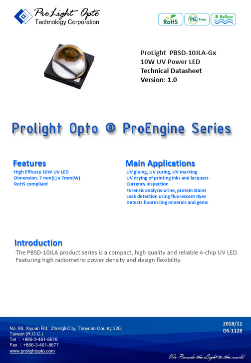
ProLight PBSD-10JLA-Gx 10W UV Power LED Technical Datasheet Version: 1.0Features‧High Efficacy 10W UV LED‧Dimension: 7 mm(L) x 7mm(W)‧RoHS compliant Main Applications‧UV gluing, UV curing, UV marking‧UV drying of printing inks and lacquers ‧Currency inspection‧Forensic analysis-urine, protein stains ‧Leak detection using fluorescent dyes ‧Detects fluorescing minerals and gemsIntroduction‧The PBSD-10JLA product series is a compact, high quality and reliable 4-chip UV LED. Featuring high radiometric power density and design flexibility.2018/11No. 89, Xiyuan Rd., Zhongli City, Taoyuan County 320,Emitter Mechanical DimensionsNotes:1. Drawing not to scale.2. All dimensions are in millimeters.3. Unless otherwise indicated, tolerances are ±0.15mm.4. Please do not solder the emitter by manual hand soldering, otherwise it will damage the emitter.5. Please do not use a force of over 0.3kgf impact or pressure on the lens of the LED, otherwiseit will cause a catastrophic failure.*The appearance and specifications of the product may be modified for improvement without notice.2 No. 89, Xiyuan Rd., Zhongli City, Taoyuan County 320,No. 89, Xiyuan Rd., Zhongli City, Taoyuan County 320, Radiometric Power (mW)Radiation PatternPart Number@1000mARefer @1400mA Color Emitter Minimum Typical Typical LambertianUV-S PBSD-10JLA-GS 200029003970UV-M PBSD-10JLA-GM 200032404428UVPBSD-10JLA-G200034404700●ProLight maintains a tolerance of ±7% on flux and power measurements.●Please do not drive at rated current more than 1 second without proper heat sink.3Flux Characteristics, T J = 25°CElectrical Characteristics, T J = 25°CForward Voltage V F (V)Forward Voltage V F (V)@1000mA Refer @1400mAColor Min.Typ.Max.Typ.UV-S 6.47.48.47.6UV-M 6.0 6.87.67.0UV6.06.87.67.0●ProLight maintains a tolerance of ±0.1V for Voltage measurements.Optical Characteristics at 1000mA, T J = 25°CTotal included Viewing Angle Angle Radiation Color Peak Wavelength λP(degrees)(degrees)PatternMin.Typ.Max.θ0.90V2 θ1/2LambertianUV-S 365 nm 367.5 nm 370 nm 6048UV-M 385 nm 387.5 nm 390 nm 6048UV390 nm395 nm400 nm6048●ProLight maintains a tolerance of ±1nm for dominant wavelength measurements.No. 89, Xiyuan Rd., Zhongli City, Taoyuan County 320, Absolute Maximum RatingsParameterUV-S/UV-M/UVDC Forward Current (mA)2000Peak Pulsed Forward Current (mA)2200 (less than 1/10 duty cycle@1KHz)ESD Sensitivity±4000V (HBM per MIL-STD-883E Method 3015.7)LED Junction Temperature 125°C Operating Board Temperature -40°C -85°Cat Maximum DC Forward Current Storage Temperature -40°C -100°C Soldering Temperature JEDEC 020c 260°CAllowable Reflow Cycles 3Reverse VoltageNot designed to be driven in reverse bias4Radiometric Power Bin Structure at 1000mAColorBin CodeMinimumMaximumAvailable Radiometric Power (mW)Radiometric Power (mW)Color BinsUV-SA 20002500AllB 25003000【1】C 30003500【1】D 35004000【1】UV-MA 20002500AllB 25003000【1】C 30003500【1】D 35004000【1】UVA 20002500AllB 25003000【1】C 30003500【1】D35004000【1】●ProLight maintains a tolerance of ±7% on flux and power measurements.●The flux bin of the product may be modified for improvement without notice. ●【1】The rest of color bins are not 100% ready for order currently. Please ask for quote and order possibility.No. 89, Xiyuan Rd., Zhongli City, Taoyuan County 320, Peak Wavelength Bin StructureColor Bin CodeMinimum Peak Maximum Peak Wavelength (nm)Wavelength (nm)UV-S 2365370UV-M A 385390UV13903952395400●ProLight maintains a tolerance of ±1nm for peak wavelength measurements.5Forward Voltage Bin StructureColorBin CodeMinimum Voltage (V)Maximum Voltage (V)UV-SB 6.4 6.8C 6.87.2D 7.27.6E 7.68.0F 8.08.4UV-MA 6.0 6.4B 6.4 6.8C 6.87.2D 7.27.6UVA 6.0 6.4B 6.4 6.8C 6.87.2D7.27.6●ProLight maintains a tolerance of ±0.1V for Voltage measurements.Note: Although several bins are outlined, product availability in a particular bin varies by production runand by product performance. Not all bins are available in all colors.No. 89, Xiyuan Rd., Zhongli City, Taoyuan County 320, 1. UV-S, UV-M, UV020406080100120140160020406080100120R e l a t i v e L i g h t O u t p u t (%)Junction Temperature, T J (℃)UV-S, UV-M, UV6Color Spectrum, T J = 25°CLight Output CharacteristicsRelative Light Output vs. Junction Temperature at 1400mA0.00.20.40.60.81.0250300350400450500550600R e l a t i v e S p e c t r a l P o w e r D i s t r i b u t i o nWavelength (nm)UV-S UV-M UVNo. 89, Xiyuan Rd., Zhongli City, Taoyuan County 320, 0102030405060708090100-100-80-60-40-20020406080100R e l a t i v e I n t e n s i t y (%)Angular Displacement (Degrees)Typical Representative Spatial Radiation PatternRadiation PatternForward Current Characteristics, T J = 25°C70.00.20.40.60.81.01.21.41.640080012001600R e l a t i v e R a d i o m e t r i c P o w e rForward Current (mA)Fig 1. Forward Current vs. ForwardVoltage for UV-S, UV-M, UV.Fig 2. Relative Radiometric Power vs.Forward Current for UV-S, UV-M, UV at T J =25 maintained.02004006008001000120014001600246810A v e r a g e F o r w a r d C u r r e n t (m A )Forward Voltage (V)UV-S, UV-M, UVUV-S, UV-M, UVSoak RequirementsLevel Floor Life Standard Accelerated Environment Time Conditions Time (hours)Conditions Time (hours)Conditions1Unlimited≤30°C /168 +5/-085°C /NA NA 85% RH85% RH●The standard soak time includes a default value of 24 hours for semiconductor manufature'sexposure time (MET) between bake and bag and includes the maximum time allowed out ofthe bag at the distributor's facility.●Table below presents the moisture sensitivity level definitions per IPC/JEDEC's J-STD-020C.Soak Requirements Level Floor Life Standard Accelerated Environment Time Conditions Time (hours)Conditions Time (hours)Conditions1Unlimited≤30°C /168 +5/-085°C /NA NA 85% RH85% RH2 1 year≤30°C /168 +5/-085°C /NA NA 60% RH60% RH2a 4 weeks≤30°C /696 +5/-030°C /120 +1/-060°C / 60% RH60% RH60% RH3168 hours≤30°C /192 +5/-030°C /40 +1/-060°C / 60% RH60% RH60% RH472 hours≤30°C /96 +2/-030°C /20 +0.5/-060°C / 60% RH60% RH60% RH548 hours≤30°C /72 +2/-030°C /15 +0.5/-060°C / 60% RH60% RH60% RH5a24 hours≤30°C /48 +2/-030°C /10 +0.5/-060°C / 60% RH60% RH60% RH6Time on Label≤30°C / Time on Label30°C /NA NA (TOL)60% RH(TOL)60% RHMoisture Sensitivity Level -JEDEC Level 1No. 89, Xiyuan Rd., Zhongli City, Taoyuan County 320,8No. 89, Xiyuan Rd., Zhongli City, Taoyuan County 320, Stress TestStress Conditions Stress Duration Failure CriteriaRoom Temperature 25°C, I F = max DC (Note 1)1000 hours Note 2Operating Life (RTOL)High Temperature 100°C, non-operating 1000 hours Note 2Storage Life (HTSL)Low Temperature -40°C, non-operating 1000 hours Note 2Storage Life (LTSL)Non-operating-40°C to 100°C, 30 min. dwell,200 cyclesNote 2Temperature Cycle (TMCL)<5 min. transferMechanical Shock 1500 G, 0.5 msec. pulse, Note 35 shocks each 6 axis Natural Drop On concrete from 1.2 m, 3X Note 3Variable Vibration10-2000-10 Hz, log or linear sweep rate,Note 3Frequency20 G about 1 min., 1.5 mm, 3X/axisSolder Heat Resistance260°C ±5°C, 10 sec.Note 3(SHR)SolderabilitySteam age for 16 hrs., then solder dipSolder coverageat 260°C for 5 sec.on leadNotes:1. Depending on the maximum derating curve.2. Criteria for judging failureItemTest Condition Criteria for Judgement Min.Max.Forward Voltage (V F )I F = max DC --Initial Level x 1.1Luminous Flux or I F = max DCInitial Level x 0.7--Radiometric Power (ΦV )* The test is performed after the LED is cooled down to the room temperature.3. A failure is an LED that is open or shorted.9Qualification Reliability TestingRecommended Solder Pad DesignStandard Emitter●All dimensions are in millimeters.●Electrical isolation is required between Slug and Solder Pad.10 No. 89, Xiyuan Rd., Zhongli City, Taoyuan County 320,No. 89, Xiyuan Rd., Zhongli City, Taoyuan County 320, 11Reflow Soldering ConditionProfile FeatureSn-Pb Eutectic Assembly Pb-Free Assembly Average Ramp-Up Rate 3°C / second max.3°C / second max.(T Smax to T P )Preheat–Temperature Min (T Smin )100°C 150°C –Temperature Max (T Smax )150°C 200°C –Time (t Smin to t Smax )60-120 seconds 60-180 seconds Time maintained above:–Temperature (T L )183°C 217°C –Time (t L )60-150 seconds60-150 secondsPeak/Classification Temperature (T P )240°C 260°C Time Within 5°C of Actual Peak 10-30 seconds 20-40 seconds Temperature (t P )Ramp-Down Rate6°C/second max.6°C/second max.Time 25°C to Peak Temperature6 minutes max.8 minutes max.●We recommend using the M705-S101-S4 solder paste from SMIC (Senju Metal Industry Co., Ltd.) for lead-free soldering.●Do not use solder pastes with post reflow flux residue>47%. (58Bi-42Sn eutectic alloy, etc) This kind of solder pastes may cause a reliability problem to LED.●All temperatures refer to topside of the package, measured on the package body surface.●Repairing should not be done after the LEDs have been soldered. When repairing is unavoidable, a double-head soldering iron should be used. It should be confirmed beforehand whether the characteristics of the LEDs will or will not be damaged by repairing.●Reflow soldering should not be done more than three times.●When soldering, do not put stress on the LEDs during heating.●After soldering, do not warp the circuit board.t 25°C to Peakt S PreheatTimeT e m p e r a t u r eCritical Zone T L to T PRamp-upRamp-downT SmaxT Smint Pt LT PT L25IPC-020cNotes:1. Drawing not to scale.2. All dimensions are in millimeters.3. Unless otherwise indicated, tolerances are ±0.10mm.12 No. 89, Xiyuan Rd., Zhongli City, Taoyuan County 320,Notes:1. Empty component pockets sealed with top cover tape.2. 500 and 750 pieces per reel.3. Drawing not to scale.4. All dimensions are in millimeters.13 No. 89, Xiyuan Rd., Zhongli City, Taoyuan County 320,Precaution for Use●StoragePlease do not open the moisture barrier bag (MBB) more than one week. This may cause theleads of LED discoloration. We recommend storing ProLight’s LEDs in a dry box after openingthe MBB. The recommended storage conditions are temperature 5 to 30°C and humidity lessthan 40% RH. It is also recommended to return the LEDs to the MBB and to reseal the MBB.●The slug is is not electrically neutral. Therefore, we recommend to isolate the heat sink.●We recommend using the M705-S101-S4 solder paste from SMIC (Senju Metal IndustryCo., Ltd.) for lead-free soldering.●Do not use solder pastes with post reflow flux residue>47%. (58Bi-42Sn eutectic alloy, etc) Thiskind of solder pastes may cause a reliability problem to LED.●Any mechanical force or any excess vibration shall not be accepted to apply during coolingprocess to normal temperature after soldering.●Please avoid rapid cooling after soldering.●Components should not be mounted on warped direction of PCB.●Repairing should not be done after the LEDs have been soldered. When repairing is unavoidable,a heat plate should be used. It should be confirmed beforehand whether the characteristics ofthe LEDs will or will not be damaged by repairing.●This device should not be used in any type of fluid such as water, oil, organic solvent and etc.When cleaning is required, isopropyl alcohol should be used.●When the LEDs are illuminating, operating current should be decide after considering thepackage maximum temperature.●The appearance, specifications and flux bin of the product may be modified for improvementwithout notice. Please refer to the below website for the latest datasheets./Use Handling of Quartz Lens LEDsNotes for handling of quartz lens LEDs●Please do not use a force of over 3.0kgf impact or pressure on the quartz lens,otherwise it will cause a catastrophic failure.●The LEDs should only be picked up by making contact with the sides of the LED body.●Avoid touching the quartz lens especially by sharp tools such as Tweezers.●Avoid leaving fingerprints on the quartz lens.●Please store the LEDs away from dusty areas or seal the product against dust.●When populating boards in SMT production, there are basically no restrictionsregarding the form of the pick and place nozzle, except that mechanical pressureon the quartz lens must be prevented.●Please do not mold over the quartz lens with another resin. (epoxy, urethane, etc)14 No. 89, Xiyuan Rd., Zhongli City, Taoyuan County 320,。
- 1、下载文档前请自行甄别文档内容的完整性,平台不提供额外的编辑、内容补充、找答案等附加服务。
- 2、"仅部分预览"的文档,不可在线预览部分如存在完整性等问题,可反馈申请退款(可完整预览的文档不适用该条件!)。
- 3、如文档侵犯您的权益,请联系客服反馈,我们会尽快为您处理(人工客服工作时间:9:00-18:30)。
House Side
2
1
0
Street Side
1
2
-2
-1
0 Horizontal S/MH
1
2
Installation Correction 5m 1.000 6m 0.694 7m 0.510 8m 0.391 9m 0.309 10 m 0.250 11 m 0.207 12 m 0.174 13 m 0.148 14 m 0.128 15 m 0.111 16 m 0.098
Distribution Curve of Meridian
-/+180 -150 -120 150 120
Conical Intensity Distribution Curve of Max Intensity
c180 c210 c240 c150 c120
-90 74 148 222 296 -30 370 0 30
γ Range: γ Interval: Test Date: Test Time: 0-90 Degree 0.9 Degree 2011-10-25 19:16:28 Temperature: 25 Celsius Humidity: 65% Test No.: Tester:
SSP6316-D50: Lamp Intensity Spatial Distribution of Tester
Vertical S/MH
(95%) 13.43 (50%) 7.07
(90%) 12.73 (40%) 5.66
(80%) 11.31 (30%) 4.24
(70%) 9.90 (20%) 2.83
(60%) 8.48 (10%) 1.41
SSP6316-D50: Lamp Intensity Spatial Distribution of Tester
20% 30% 40% 50% 60% 70% 80% 90%
73 110 146 183 220 256 293 329
CIE: cut-off CIE: short-narrow extension
Imax: 366(H2.5,V14.2) Unit: cd
Horizontal Degree (DEG)
γ180
170
160 150 140 130 120 110 100
Road Lamp Type
CIE: CIE:
cut-off short-narrow extension IES: cut-off IES: II-very short Max.At80: 7.82cd/klm Max.At90: 7.0619cd/klm Isocandela Curve(Round Net) Intensity Unit cd Imax = 100% 366 90% 330 80% 293 70% 257 60% 220 50% 183 40% 147 30% 110 20% 74 10% 37
SSP6316-D50: Lamp Intensity Spatial Distribution of Tester
Page 1/8
Photometric Data of Lamp
Lamp Description
Lamp Name: 10w Lamp Type: Light Type: Light Standard: Lamp Size: Rated V oltage: Light Number: Light Area: Lamp Weight: Rated Power: Rated Flux: Light Flux:
Temperature: 25 Celsius Humidity: 65% Test No.: Tester:
SSP6316-D50: Lamp Intensity Spatial Distribution of Tester
Page 6/8
Isocandela Curve of Lamp
Lamp Description
Lamp Name: 10w Lamp Type: Light Type: Light Standard: Lamp Size: Rated V oltage: Light Number: Light Area: Lamp Weight: Rated Power: Rated Flux: Light Flux:
γ Range: γ Interval: Test Date: Test Time:
0-90 Degree 0.9 Degree 2011-10-25 19:16:28
Temperature: 25 Celsius Humidity: 65% Test No.: Tester:
SSP6316-D50: Lamp Intensity Spatial Distribution of Tester
1.75 2 -3 -2 -1 0 1 2 3
Imax: 366 Unit: cd
c Range: 0-360 Degree c Interval: 10 Degree Test Speed: Fast Test Distance: 5 m Note:
-2.25
2.25
Horizontal S/MH
270
285
300
315
330
345
C0
15
30
45
60
75
90
80 70 60 50 40 30 20
House Side
γ0
10
Street Side
c Range: 0-360 Degree c Interval: 10 Degree Test Speed: Fast Test Distance: 5 m Note:
SSP6316-D50: Lamp Intensity Spatial Distribution of Tester
Page 3/8
Isocandela Curve of Road Lamp (Round Net Curve)
Lamp Description
Lamp Name: 10w Lamp Type: Light Type: Light Standard: Lamp Size: Rated V oltage: Light Number: Light Area: Lamp Weight: Rated Power: Rated Flux: Light Flux:
Utilization Factor Curve of Road Lamp
HoБайду номын сангаасse Side
Horizontal Isophotes Curve
Horizontal Absolute Isophotes Curve
Height of calculation: 5.00 m, Illumination in the vertical of Lamp: 14.14 lx If Height of Installation is not equal to Height of Calculation, please calculate by table of Correction Factor
90
Illumination Cone Curve
H[m] Diameter[m] Illuminance[lx]
1.0
353.84 353.22 88.46 88.31 39.32 39.25 22.12 22.08 14.15 14.13 C0-C180 C90-C270
2.0
3.0
4.0
5.0
Page 5/8
Isocandela Curve of Lamp
Lamp Description
Lamp Name: 10w Lamp Type: Light Type: Light Standard: Lamp Size: Rated V oltage: Light Number: Light Area: Lamp Weight: Rated Power: Rated Flux: Light Flux:
Measured Data of Lamp
V oltage: 225.5 V Total Flux Lamp Efficiency Peak Intensity Half-Intensity Angle Upward Light Ratio Upward Street Side Upward House Side Flash Area(76°) Current: 0.084 A 816.15 lm 0.00% 365.88 cd 97.2° 0 0 0 0 cm2 Power: 10.6 W Central Intensity Light Efficiency Location of Peak(c,γ) Beam Angle Downward Light Ratio Downward Street Side Downward House Side Discomfort Glare(SLI) Power Factor: 0.556 353.53 cd 77.00 lm/W (80.0°, 14.4°) 115.2° 100% 430.12 lm 386.03 lm 0
Page 4/8
Lamp Utilization Factor Curve
Utilization Factor(%) 100 Elevation Legend 0.0° 90 5.0° 10.0° 80 15.0° 70 20.0° 60 50 40 30 20 10 0 2 1 0 1 Street Side 2 3 4 Horizontal S/MH
90
c270 74 148 c300 222 296 c330 370 c0 c30 c60