行车电脑Hobd软件安装使用说明
路虎IDS安装说明
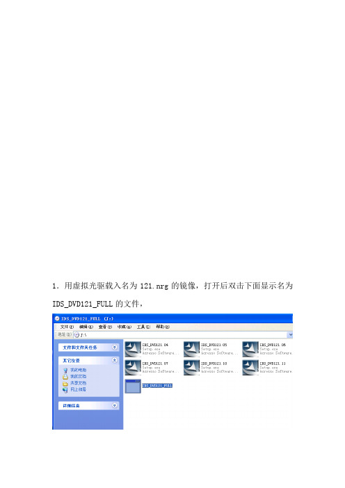
1.用虚拟光驱载入名为121.nrg的镜像,打开后双击下面显示名为IDS_DVD121_FULL的文件,2.开始进行安装设置,选择简体中文语言,点击下一步3.接着弹出下面界面,继续点击下一步4.选择接受许可协议,并打击下一步。
5.选择我已经阅读,点击下一个,如下图所示。
6.选择安装路径,注意磁盘容量,选择好后点击下一个进行下一个设置。
7.安装设置完毕,点击安装,开始安装软件。
8.下面是软件的安装过程,这里要持续一段时间,请耐心等待。
9.安装即将结束,会弹出一个对话框,这里直接点击是。
10.安装完成界面,点击完成,重启电脑。
11. 重启电脑之后,进入软件的安装目录下(这里以F盘为例),找到F:Program Files\JLR\IDS\Runtime目录,找到SysPage文件,下图所示,并双击运行。
12.运行之后会有选择国家的对话框,这里选择中国,并点击打勾按钮,如下图所示。
13.接着选择地区,这里选择Beijing,并点击打勾按钮,如下图所示14.注意这里不能选择其他,要随便选择一个地区,然后打勾。
15.打开软件进入系统功能,点击网络选项,进行网络设置。
17.设置好网络后,选中编译文件和校准文件组合更新,然后点击打勾按钮,如下图所示。
18.进入软件管理向导,这里要上网在线下载,所以要一直接上能上网的网线,直接点击下一步。
19.开始下载,下面是下载过程,不能断开网络。
20.下载完毕后,接着下载校准文件,选择所有车辆,然后点击下一步,这也是要保持网络一直连接。
21.接着会弹出下面界面,点击下一步开始下载,保持网络连接,知道下载结束,软件就安装成功了。
2013年Honda车载辅助设备安装说明书
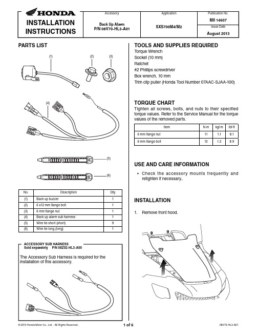
Issue DateAugust 2013INSTALLATION INSTRUCTIONSAccessory Application Publication No.MII 14607PARTS LISTBack Up AlarmP/N 08V70-HL3-A01SXS700M4/M2No.Description Qty (1)Back up buzzer1(2) 6 x12 mm flange bolt 1(3) 6 mm flange nut1(4)Back up alarm sub harness 1(5)Wire tie short (short)9(6)Wire tie long (long)1TORQUE CHARTTighten all screws, bolts, and nuts to their specified torque values. Refer to the Service Manual for the torque values of the removed parts.ItemN·m kgf·m Ibf·ft 6 mm flange nut 11 1.18.16 mm flange bolt121.28.9USE AND CARE INFORMATION• Check the accessory mounts frequently andretighten if necessary..TOOLS AND SUPPLIES REQUIREDTorque WrenchSocket (10 mm)Ratchet#2 Phillips screwdriver Box wrench, 10 mmTrim clip puller (Honda Tool Number 07AAC-SJAA-100)INSTALLATION1. Remove front hood.(6)3. Lift the cargo bed.4. Remove right rear foot well (M4 type only).2.Remove the bench seat.5.Remove right rear step as shown (M4 type only).TRIM CLIP TRIM CLIP6 mm FLANGE BOLT6. Remove rear center cover as shown.REAR CENTER COVER8. Install the back up alarm buzzer.NOTE:•Angle alarm to avoid contact with breather hose.7. Remove the left rear foot well as shown (M4 typeonly).TRIM CLIPTRIM CLIP6 mm MUD GUARD SCREW9. Connect the back up alarm buzzer to the back upalarm sub harness.Secure connectors with a wire tie as shown.BACK UP ALARM BUZZERCONNECTORSWIRE TIEVEHICLE’SMAIN HARNESS6 mm FLANGE BOLT 6 mm FLANGE NUTALARM BUZZERBACK UP ALARM SUB HARNESS10. Release the gear position switch (3P black)connector from the connector stay.Disconnect the gear position switch connector.12. Secure the connectors to the gear position switchwire with a wire tie.BACK UP ALARM SUB HARNESS AND GEAR POSITIONSWITCH CONNECTORSWIRE TIEGEAR POSITION SWITCH WIREGEAR POSITIONSWITCH CONNECTOR (3P black)CONNECTOR STAYBACK UP ALARM SUB HARNESSGEAR POSITIONSWITCH CONNECTOR (ENGINE SIDE)GEAR POSITIONSWITCH CONNECTOR (HARNESS SIDE)BACK UP ALARMSUB HARNESSBACK UP ALARM BUZZERACCESSORY SUB HARNESS (sold separately)p11. Connect the back up alarm sub harness betweenthe gear position switch connectors as shown.14. Secure the back up alarm harness to main harnessnear back of engine, under the passenger seat, with a wire tie.15. Secure the back up alarm harness to the mainharness near the front of the engine, under passenger seat, with wire tie. NOTE:• Tie only to the main harness and not the cables.16. Secure the back up alarm harness to the mainharness, near frame joint, with a wire tie.BACK UP HARNESSWIRE TIEMAIN HARNESSWIRE TIEMAIN HARNESS BACK UP HARNESSWIRE TIEBACK UP HARNESS13. Secure the back up harness to the main harness witha wire tie so that it does not contact the alternator wires.Reinstall the connector to the connector stay.WIRE TIEMAIN HARNESSALTERNATOR WIRES BACK UP ALARM HARNESSENGINEENGINE18. Follow the main harness and secure the back upalarm harness to the inside of the main harness as shown.19. Secure the back up alarm harness to the inside of themain harness with a wire tie as shown, then route it behind the fusebox.20. Disconnect and replace the original equipmentaccessory socket sub harness with the Accessory Sub Harness as shown.Connect the back up alarm sub harness to the accessory sub harness with the single bullet connector.Secure the harnesses to the frame with a wire tie as shown.MAIN HARNESSBACK UP HARNESSWIRE TIEWIRE TIESUB HARNESSFRAME17. Secure the back up alarm harness to the inside of themain harness, near the passenger footwell, with a wire tie.BACK UP HARNESSWIRE TIEMAIN HARNESSBACK UP HARNESSWIRE TIE MAIN HARNESS<Right front upper wheel well>TO HORNVEHICLE HARNESSVEHICLE ACCESSORY SOCKETBULLET CONNECTOR TO BACK UP ALARMACCESSORY SUB HARNESS21. Refer to the Service Manual and reinstall thevehicle’s parts in the reverse order of removal.。
汽车导航DVD播放器的安装说明
汽车导航DVD播放器的安装说明安装汽车导航DVD播放器的说明一、准备工作在开始安装导航DVD播放器之前,请确保已经具备以下材料和工具:1. 汽车导航DVD播放器;2. 汽车配电箱的工具组;3. 螺丝刀;4. 扳手;5. 绝缘胶带;6. 电缆线。
二、安装步骤1. 确定安装位置在安装之前,需要选择一个合适的位置安装导航DVD播放器。
通常,这个位置应该是在汽车仪表板上,足够接近驾驶员并且方便观看。
可以将播放器放置在仪表板的中央位置,但不得遮挡视线。
请注意,安装位置应该符合相关安全规定,并确保播放器的安全性和稳定性。
2. 固定导航DVD播放器使用螺丝刀和扳手将播放器固定在所选择的位置上。
可以根据导航DVD播放器的底部安装孔的位置,在汽车的仪表板上打孔。
确保螺丝固定牢固,以防止播放器在行驶中松动或掉落。
3. 连接电源将导航DVD播放器连接到汽车的电源系统。
这一步需要注意电源线的连接。
首先,确保汽车的电源已经关闭。
然后,使用配电箱的工具组打开汽车的配电箱。
找到适合的电源接口,并使用绝缘胶带将导航DVD播放器的电源线连接到电源接口上。
请务必确保电源线的连接牢固,并将其绝缘以防止电路短路。
4. 连接音频和视频将导航DVD播放器与汽车的音频和视频系统连接起来。
首先,找到汽车音频和视频输入接口。
然后,使用音频和视频线将导航DVD播放器的音频输出和视频输出连接到汽车音频和视频输入接口上。
确保连接牢固且不会松动。
5. 完成安装在完成以上步骤后,请重新检查导航DVD播放器以确保所有连接都正确且牢固。
然后,将汽车的配电箱关闭,并将其安全固定。
最后,将汽车电源打开并启动汽车,测试导航DVD播放器是否能正常工作。
三、使用说明安装完成后,您可以根据需要使用导航DVD播放器进行各种操作。
以下是一些使用导航DVD播放器的基本说明:1. 打开导航DVD播放器的电源,启动系统;2. 使用操作面板或遥控器选择所需的功能,如导航、音频、视频等;3. 如果使用导航功能,请按照屏幕上的指示输入目的地信息,并选择导航方式(如最快路线、最短路线等);4. 播放音频或视频时,请确保车辆已停放在安全位置,并遵守当地交通规定。
2009 Honda Accord Prelude RL 车载警报与远程启动系统安装指南说明书
Page 4 of 4
ADS-TB-PR
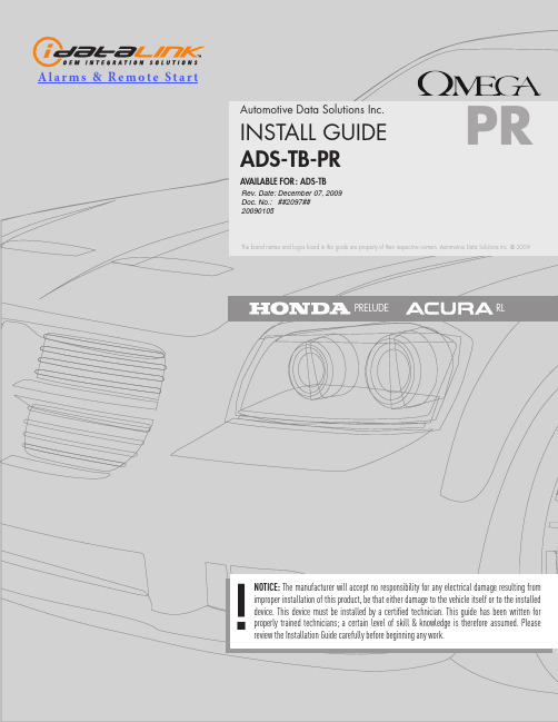
moduLE diagnostics
MODULE DIAGNOSTICS DURING PROGRAMMING
Doc. No.: ##2097## 20090105
SOLID RED MODULE WAITING FOR MORE VEHICLE INFORMATIONS
FACTORY RESET
FACTORY RESET PROCEDURE
2 Press and hold the programming button while inserting either the 4-PIN standard or 4-PIN optional data connector.
PIN DATA WIRE PIN GROUND
4 Black/Yellow
3 Light Blue
6 Brown/Yellow 8 Black
4 Yellow/Black
3 Light Blue
6 Brown/Yellow 8 Black
4 Yellow/Black
3 White/Red
6 White
LEGEND Wiring connections not required when installed in iDatalink mode
* Wiring connection not required in 2-way iDatalink
RED - 12V BLACK - GROUND NO WIRE (NC) BLUE/WHITE - GROUND-OUT WHEN RUNNING
HOLD
INSERT 4SHES RED, RELEASE THE BUTTON
车载录像管理软件说明书

车载DVR录像管理软件使用说明书车载DVR录像管理软件使用说明书V1.1.0目录目录 (i)1 产品介绍................................................................................................................................ - 1 -1.1产品简介 ............................................................................................................................................. - 1 -1.2基本性能 ............................................................................................................................................. - 1 -2 安装指南................................................................................................................................ - 2 -2.1 安装步骤.............................................................................................................................................. - 2 -2.2 打开方式.............................................................................................................................................. - 6 -3 界面基本操作 ........................................................................................................................ - 7 -3.1 系统菜单栏.......................................................................................................................................... - 8 -3.1.1 快速定位..................................................................................................................................... - 8 -3.1.2 查找录像..................................................................................................................................... - 8 -3.1.3 地图 ...........................................................................................................................................- 10 -3.1.4 日志查询....................................................................................................................................- 15 -3.1.5 硬盘格式化 ................................................................................................................................- 16 -3.1.6 系统配置....................................................................................................................................- 17 -3.1.7 版本信息....................................................................................................................................- 19 -3.2 文件列表栏.........................................................................................................................................- 21 -3.2.1 起始位置预览 ............................................................................................................................- 22 -3.2.2 切片预览....................................................................................................................................- 23 -3.2.3 水印检测....................................................................................................................................- 24 -3.2.4 查找录像....................................................................................................................................- 26 -3.2.5 备份录像....................................................................................................................................- 27 -3.3 录像播放窗口 .....................................................................................................................................- 29 -3.3.1 局部放大....................................................................................................................................- 29 -3.3.2 其他功能介绍 ............................................................................................................................- 31 -3.4 窗口切换栏.........................................................................................................................................- 31 -3.5 回放工具栏.........................................................................................................................................- 31 -3.5.1 工具栏........................................................................................................................................- 31 -3.5.2 单通道和全通道剪切.................................................................................................................- 32 -3.6 播放进度条.........................................................................................................................................- 33 -4 系统配置...............................................................................................................................- 34 -5 软件限制...............................................................................................................................- 35 -6 FAQ问答 ..............................................................................................................................- 36 -车载DVR录像管理软件产品介绍1 产品介绍1.1产品简介车载DVR录像管理软件是安装在PC上的软件,配合SATA-USB转接盒或闪存卡读卡器使用。
车载OBD说明书
1,为什么加油灯一直闪烁报警?原因和解决:一,如果第9项的油量开关设置为1,表示使用汽车液位传感器计算油量,国内80%的汽车不带有这个传感器,所以设置为1,就会报警,那么改成0,表示手动输入油量,问题解决;或者设置为2关闭,问题解决。
二,如果没有设置过9项,默认值为0,表示手动输入的油量,行驶一段时间后,会出现加油灯报警,是因为里面预设的油量已经低于10L,则显示了续航里程,KM图标亮起,这时可以多次左拨开关,直到888位置显示的值超过10,则加油图标停止闪烁,问题解决;这个操作表示已经快速加油,如果加的数量为自己本车的油量,那么可以作为正常续航里程,下次汽车油量低于10L,自动亮起。
2,为什么HUD行驶过程中会自动重启?原因和解决:一,第9项设置为1,表示使用汽车液位传感器计算油量,由于汽车没有这个传感器器,HUD会不断的检测这个数据,长时检测会导致其他数据的收发变慢,转速数据有可能丢失,这样HUD会自动关机,但汽车电压维持在13.2V以上,HUD又会自动启动工作,所以导致重启问题;设置为0或者2,问题解决。
二,第11项设置为排量方法计算油耗,油耗无法正常显示,有可能导致HUD重启,原因也同上,HUD检测了两个传感器数据用来计算油耗,获取不到数据导致,此时设置为0,使用空气流量传感器计算油耗,油耗正常显示,问题解决。
同理,如11项开始设置为0,导致的重启问题,那么改为排量计算油耗,问题解决。
3,为什么无法设置油耗为L/100KM的单位原因和解决:在HUD软件里面的设置为L/H和L/100KM自动切换方式,即每小时油耗和每百公里油耗自动切换,这样更利于了解汽车油耗,因为停车时L/100KM的数值为0,原因是这种算法是用油量除以距离,可是速度为了,不产生距离,油量除以0,那么等于0;你在等待红灯时,显示油耗为0,对你来说没什么意义。
所以自动切换到L/H显示。
那么这么说,停车时显示L/H,开车后就显示L/100KM;但是如果你动过默认的设置,一直显示的油耗单位是L/H,那么左拨开关5秒,L/H闪烁,再拨一次,L/100KM闪烁,然后按下开关5秒保存退出,设置完成,那么显示又跳到了L/H单位亮了,这是正常的,因为你此时速度为0,只能显示L/H的单位,只要车开起来就行了,不要纠结。
OBD一键启动安装简单
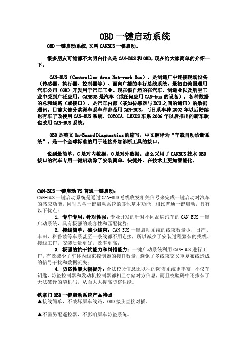
OBD一键启动系统OBD一键启动系统,又叫CANBUS一键启动。
很多朋友可能都不太明白什么是CAN-BUS和OBD,现在给大家简单的介绍一下。
CAN-BUS(Controller Area Net-work Bus),是制造厂中连接现场设备(传感器、执行器、控制器等)、面向广播的串行总线系统,最初由美国通用汽车公司(GM)开发用于汽车工业。
现在很自然的在汽车、制造业以及航空工业中受到广泛应用。
CANBUS是汽车(或任何应用CAN-bus的设备),各种数据的总和线路(或接口),是汽车内部(某如传感器与ECU之间的通讯)的数据通讯。
目前大部分欧洲车系车种都是用CAN-BUS,而日系车种2002年以后陆续也有车子改使用CAN-BUS系统,TOYOTA、LEXUS车系2006年以后推出的新车款也改用CAN-BUS系统。
OBD是英文On-Board Diagnostics的缩写,中文翻译为“车载自动诊断系统”。
是一个全球标准的用于连接外加诊断工具的接口。
说到最简单,C是对内数据,O是对外数据。
那么采用了CANBUS技术OBD 接口的汽车专用一键启动除了安装简单、快捷外,在技术上更加智能化。
CAN-BUS一键启动VS普通一键启动:CAN-BUS一键启动系统是通过CAN-BUS总线收发相关信号来完成一键启动对汽车的感应功能,同时具备一键启动系统的其他基本功能,相比普通一键启动,具有以下优点:1. 专车专用,针对性强:专业开发的针对不同品牌汽车的CAN-BUS一键启动系统,具有极强的兼容性和匹配优势;2. 接线简单,减少线束:CAN-BUS一键启动系统的线束数量少,日产、丰田、科鲁兹等车系甚至一条线都不用连接,所以减少了安装过程繁杂的找线、接线工作,安装质量更好,效率更高;3. 极强的抗干扰能力和纠错能力:一键启动系统利用CAN-BUS进行工作,有效减少了车体内线束控制器的接口数量,避免了多线束交叉重复布线造成的信号干扰和数据流失;4. 防盗性能大幅提升:合法校验信息比以往的防盗系统更丰富,不仅车钥匙、防盗控制器和发动机控制器都相互存储对方信息,而且校验码中还掺杂了无法破译的随机码,从而大大提高防盗性能。
HUDDLECAMHD串口摇杆控制器HC-JOY-G2安装和操作手册说明书

HuddleCamHD Serial Joystick ControllerModel Number: HC-JOY-G2Joystick Keyboard Installation & Operation ManualEasy pan, tilt & zoom controls for any RS-232, RS485, RS422 VISCA, Pelco-P or Pelco-D protocol camera!Controls pan & tilt with variable speed.Uses 3 dimensional joystick with “twist” control for variable zoom.Key Product Features•All Metal housing.•VISCA, PELCO-D and PELCO-P protocol support.•Large LCD Menu display.•Key-press “BEEP” confirmation (optional – set on or off).•Pan, tilt, zoom, iris and focus control.•Variable speed control of pan, tilt and zoom.•Auto/Manual Focus and Iris.•Backlight Compensation control.•Cameras #1-4 ‘Quick Key’ Select buttons.•Preset Save, Call and Clear.•Real time display of the current status.•Short circuit and overcurrent protection.•Automatic recovery program for the communication port(s).•Control Interfaces:RS232 full-duplex, RS485 semi duplex, RS422 full-duplex.•Variable Baud Rate 1200 to 19200 bps.•Maximum communication distance: RS485: 3,937ft [1200m] using 24 gauge twisted pair cabling•Can control a maximum 255 cameras.•Voltage: 12VDC.•Power Consumption: 6W Max.•Display: LCD.•Working Temperature: 14°F ~ 122°F [-10° ~ +50° C].•Working Humidity: 10 ~ 90% (non-condensation).•Weight 3.4 lbs. [1.6 kg]•Dimensions:12.6”(W) x 7.1”(D) x 4.3”(H) [320mm x 181mm x 110mm].In the Box•Keyboard with three-axis control joystick.•5p screw terminal plug (RS422/RS485).•12VDC Power Supply.•This Manual.•Power Supply Interface (5.5mm x 12mm center pin JEITA style jack): 12VDC / 2000mA power supply.•RS485/422 interface (5p screw terminal):1:485+/422TxA, 2:485-/422TxB, 3:422RxA, 4:422RxB, 5:485/422Gnd.•RS232 interface (DB9M port): 2:Rx, 3:Tx, 5:Gnd.•Keys: momentary push buttons (keys).•Joystick: 3-axis joystick.•Digital display: LCD display.•VISCA, PELCO-P and PELCO-D protocol support.•Control interfaces:o5p Screw Terminal (RS485/RS422).o DB9 (RS232).•Baud rate: 1200, 2400, 4800, 9600, 19200.•Parameters: 8 bits, 1 stop bit, N o parity.Keyboard/Joystick OperationBasic Control•Pan & Tilt Controlo Joystick movement provides variable speed pan and tilt of thecamera head.•Zoom Controlo Rotation of the joystick controls variable speed zoom of the lens.▪Clockwise rotation of the joystick = zoom in.▪Counter-clockwise rotation of the joystick = zoom out.o Incremental Zoom control can also be achieved using thefollowing keys: “Zoom+”, “Zoom-”.Manual Control Options•Focus Control – (VISCA Only, Pelco-P &-D do not provide for “Man Foc”) o Incremental Focus control can also be achieved using thefollowing keys: “Focus+”, “Focus-” (“Man Foc” must first beenabled).o Auto Focus may be enabled by pressing the “Aut Foc” key.o Manual Focus may be enabled by pressing the “Man Foc” key.o Pressing the “Esc” key (while not in a configuration menu) willcycle through 8 levels of manual focus speed: 0-7. The currentManual Focus speed setting may be seen in the top right corner ofthe LCD display as ‘FS:0’ though ‘FS:7’•Iris Control – (VISCA Only, Pelco-P &-D do not provide for “Man Exp”) o Incremental Iris control can also be achieved using the following keys: “Iris+”, “Iris-” (“Man Exp” must first be enabled).o Auto Iris may be enabled by pressing the “Aut Exp” key.o Manual Iris may be enabled by pressing the “Man Exp” key. Note: Some cameras do not have an “Iris” (or manual Iris) mode. Forthis reason, Manual Exposure is used. Therefore, for best results,use the camera’s IR remote to first select a desired shutter speedbefore using “Man Exp”, “Iris+ ”and “Iris-“•Backlight Compensation Control – (VISCA Only, Pelco-P &-D do not provide for BLC)o Backlight Compensation may be enabled by pressing the “BLC On”key. Use this setting for shooting backlit subjects.o Backlight Compensation may be disabled by pressing the “BLCOff” key. Use this setting for shooting subjects with balanced, 3point, overhead or front lighting.Selecting a Camera•Input Number Keyso For entering numbers use the “0” t hrough “9” keys.o Press “Enter” key to complete commands.o Press the “Clear” key to clear entries before confirming with“Enter” key.•Set the Camera ID to be controlled by joysticko Press “Addr” key, desired “Number” k ey and then “Enter” key.o Alternatively you can use the “Cam 1” through “Cam 4” quick-select buttons to quickly access cameras 1-4.PTZ Presets•Set a PTZ Preseto Use joystick and keyboard to set up the desired preset shot. Press the “Set” key, press a “Number” key and then the “Enter” key. Toleave “Set” mode, press the “Esc” key.•Call a PTZ Preseto Press the “Call” key, press a “Number” key and then the “Enter”key.o You may leave the unit in “Call” mode and continue to enter sequential preset calls. To leave “Call” mode, press the “Esc” key.•Clear a PTZ Preseto Press “Esc” key to return to main menu. Press the “Clear” key, press a “Number” key and then the “Enter” key. To leave “Clear”mode, press the “Esc” key.•Send camera to its “Home” PTZ Positiono Press the “Home” key. Note: When in Pelco-P or –D, this button will call preset 0, instead of Home. Pelco-P and –D do not providefor a “Home” position. You must first set preset 0 to use thisfeature with Pelco)Notes on using presets with VISCA:For your convenience, the HC-JOY-G2 uses the same preset numbers wheth er ‘set’, ‘called’ or ‘cleared’ via hand-held IR remote, VISCA, Pelco-P or Pelco-D. This is in contract to Sony’s traditional offset of -1 between IR remote commands and VISCA commands. If you are used to Sony’s traditional method, you no longer need to make this adjustment.•Go to Main Menu or Backup up one Menu Levelo Press “Esc” key to return to main menu. Note: Repeated presses may be required depending on how deep you are in a menu.Note: Pressing the “Esc” key while not in a menu will change themanual focus speed.•Obtain Product Informationo Press the “Info” key.o Use Joystick “Up” and “Down” to scroll through info (Model, Serial Number, Keyboard ID, Key Sound setting).•Configure Keyboard/Joysticko Press and Hold the “Setup” key for 3 seconds.o Enter the password. “8888” is the default password.o Press the “Enter” key.•Keyboard Menuo“Set >>” Menuo Move joystick “left” and “right” to select between 1(CAM) or2(SYS)o Press “Enter” key to confirm the choice.o“SET >>CAM” : Menu▪Move Joystick “left” and “right” or simply type camera ID to select camera to configure.▪Press “Enter” key to confirm the choice.▪Move Joystick “up” and “down” to choose between setting either the control protocol or baud rate settings.▪Move Joystick “left” and “right” to select the desired control protocol or baud rate (to match that of camera).▪Repeat for all camera IDs required.▪Press “Esc” to return to previous menu level.o“SET >>SYS” : Menu▪Move Joystick “left” and “right” to select system parameter to configure.▪Press “Enter” key to confirm the choice.▪1(EDIT PW)•OLD PW: Using “Number” keys, enter the currentpassword (default = “8888”). Press “Enter” key toconfirm.•NEW PW: Using “Number” keys, enter the desiredpassword (4 numeric keys) Press “Enter” key toconfirm.•AGAIN PW: Using “Number” keys, re-enter the desired password (4 numeric keys) Press “Enter” key toconfirm.▪2(FACTORY)•SURE?: Press “Enter” key to confirm.▪3(LOAD ISP)•Press “Enter” key to confirm.•SURE?: Press “Enter” key to confirm.▪4(SOUND)•Move Joystick “left” and “right” to turn key beep ON or OFF.•Press “Enter” key to confirm.▪5(KB ID)•KB ID: Using “Number” keys, enter the desired ID.Press “Enter” key to confirm.▪6(LOCK SET)•Move Joystick “left” and “right” to turn KB lock ON orOFF. Press “Enter” key to confirm.•LOCK PW: Using “Number” keys, enter the desiredpassword (4 numeric keys). Press “Enter” key toconfirm.•To unlock Keyboard/Joysticko Press “Esc” key until LCD shows “LOCKED”o LOCK PW: Using “Number” keys, enter thedesired password (4 numeric keys). Press“Enter” key to confirm.o LCD screen will go Black. Press “Enter” keyagain.o OPEN LOCK: Using “Number” keys, enter thedesired password (4 numeric keys). Press“Enter” key to confirm.Indicators:•“PW” illuminates Red when unit is powered•“TXD” flashes green when unit is transmitting commands•“RXD” flashes green when unit is receiving responsesPower:•Keyboard/Joystick requires external 12VDC. Use only the 12VDC power supply shipped with the unit.The Keyboard/Joystick may be connected to cameras via RS232, RS485 or RS422.•For RS232, connect the DB9 port of the KB to the miniDin8 (VISCA) port of the camera with pin-out as follows:o KB Tx –Pin 3 ---------- Camera Rx - Pin 5o KB Rx –Pin 2 ---------- Camera Tx - Pin 3o KB Gnd –Pin 5 ---------- Camera Gnd - Pin 4•For RS485, connect the 5p screw terminal port of the KB to the RS485 port of the camera with pin-out as follows:o KB Ta –Pin 1 ---------- Camera (+)o KB Tb –Pin 2 ---------- Camera (-)o KB Gnd –Pin 5 ---------- Camera (G) (if present – some cameras will not require a G)•For RS422, connect the 5p screw terminal port of the KB to the RS422 port of the camera with pin-out as follows:o KB Ta –Pin 1 ---------- Camera (Rx-)o KB Tb –Pin 2 ---------- Camera (Rx+)o KB Ra –Pin 3 ---------- Camera (Tx-)o KB Rb –Pin 4 ---------- Camera (Tx+)o KB Gnd –Pin 5 ---------- Camera (G) (if present – some cameras will not require a G)•Cannot Control Camera at allo Check that LCD is in the Main Menu. Press “Esc” key to return to main menu, if needed. Note: Repeated presses may be required depending onhow deep you are in a menu, e.g. this can often happen after settingpresets and then attempting to Call presets without exiting the Setmenu.o Check that PW Indicator is solid Red. If not, check power supply connection to KB and AC Mains. If still unlit, power supply or KB may bedamaged.o Check both KB settings and Camera settings to ensure that the following ALL match:▪Camera ID (e.g. 01, 02, etc…)▪Camera Protocol (e.g. VISCA, PELCO-P, PELCO-D)▪Baud Rate (e.g. 9600)o Check all KB-Camera connections and cabling per “Connection Wiring and Indicators” section above.o Check TXD Indicator for Green flickering when cam is moved using the joystick. If not flickering, KB or its joystick may be damaged. •Controlling more than 1 camera at a time.o Check all cameras to ensure that each has a unique ID.o Check all camera settings in KB menu to make sure that the protocol setting for that camera ID matches that of the actual camera.o Note, you cannot typically mix VISCA, Pelco-P or Pelco-D cameras in the same daisy chain.o Check control wiring.▪For RS232, cabling must flow from KB into the VISCA-in port of the first camera and then from VISCA-out port of first camera toVISCA-in port of next camera, etc... With daisy chained RS232, noterminator is required on the last camera. A VISCA cross-overcable must be used for all camera to camera connections. Theseare available from HuddleCamHD in various lengths as well asfrom other sources.▪For RS485 and RS422, all connections are in parallel (e.g. allcams’ 485+ are connected to KB’s 485+ and all cams’ 485- areconnected to KB’s 485-) and termination may be requireddepending upon overall cabling distances involved.。
使用HUD显示器进行汽车行驶辅助的步骤

使用HUD显示器进行汽车行驶辅助的步骤在现代社会中,汽车已经成为人们生活中不可或缺的一部分。
随着科技的不断进步,汽车行驶辅助系统也得到了广泛的应用。
其中,HUD(Head-Up Display)显示器作为一种新兴的辅助工具,为驾驶员提供了更加安全和便捷的驾驶体验。
本文将介绍使用HUD显示器进行汽车行驶辅助的步骤,帮助读者更好地了解和使用这一技术。
首先,使用HUD显示器进行汽车行驶辅助的第一步是安装和设置。
HUD显示器通常是安装在汽车的仪表板上,需要将其与车辆的电源和数据系统连接。
在安装过程中,需要按照HUD显示器的说明书进行操作,确保连接正确并且牢固。
安装完成后,还需要进行一些设置,如调整显示器的亮度、颜色和位置等,以适应驾驶员的个人需求。
第二步是了解HUD显示器的功能和使用方法。
HUD显示器通常可以显示车速、导航信息、车道偏离警示等内容。
在使用前,驾驶员需要熟悉显示器上不同信息的显示方式和含义。
一般来说,车速信息会以数字或者图形的形式显示在驾驶员的视线范围内,以便驾驶员在行驶过程中能够随时了解自己的车速。
导航信息则会显示当前位置、行驶方向和下一个转弯等重要信息,帮助驾驶员更好地导航。
车道偏离警示功能可以通过显示器上的箭头或者声音提醒驾驶员注意车辆是否偏离了当前车道。
第三步是合理使用HUD显示器。
虽然HUD显示器可以提供很多有用的信息,但驾驶员在使用时也需要注意适度和安全。
首先,驾驶员应该根据自己的需求和驾驶环境选择显示的信息,避免过多的信息干扰驾驶。
其次,驾驶员在驾驶过程中应该将注意力集中在道路上,而不是过度依赖显示器。
HUD显示器只是辅助工具,驾驶员仍然需要保持警觉和专注。
最后,驾驶员应该遵守交通规则,不要将HUD显示器用于违法驾驶行为,以确保行车安全。
除了上述步骤,使用HUD显示器进行汽车行驶辅助还需要注意一些其他方面。
首先是定期检查和维护。
HUD显示器是一种电子设备,需要定期检查其工作状态和连接情况,确保其正常运行。
朗动行车电脑设置方法
朗动行车电脑设置方法朗动行车电脑是一款集合了导航、多媒体、车辆信息等功能的智能车载设备。
以下是朗动行车电脑的设置方法,分为硬件设置和软件设置两部分:硬件设置:1. 确认朗动行车电脑的安装位置:一般情况下朗动行车电脑位于车辆的中控台上方,需要确认安装位置没有遮挡物和妨碍视线的问题。
2. 连接电源:确保朗动行车电脑的电源线与车辆的电源线连接,确保接触良好。
3. 连接音频和视频输入:根据车辆的音频和视频输出接口,连接朗动行车电脑的音频和视频输入线,这样可以实现音频和视频的播放和输出。
4. 连接外部设备:如果需要使用外部设备如麦克风、USB接口等,需要根据朗动行车电脑的接口类型进行相应的连接。
软件设置:1. 开机启动:将车辆点火,按下朗动行车电脑上的电源开关,待屏幕亮起后,系统会自动进入主界面。
在主界面中,找到“设置”选项,点击进入。
2. 蓝牙连接:点击设置中的“蓝牙”选项,可以搜索并连接周围的蓝牙设备,如手机、耳机等。
根据提示完成蓝牙设备的配对和连接。
3. 导航设置:点击设置中的“导航”选项,可以设置导航声音的音量、导航语言、导航路线的偏好等。
还可以设置家庭地址和公司地址,在导航时更加便捷。
4. 播放设置:点击设置中的“音乐”选项,可以设置音乐播放的声音效果、音频设备的连接方式等。
还可以设置音乐的分类和播放模式,满足个人的音乐喜好。
5. 车辆信息:点击设置中的“车辆”选项,可以查看和设置车辆的相关信息,如车辆的行驶里程、油耗等。
还可以进行故障码的读取和清除等操作。
6. 多媒体设置:点击设置中的“多媒体”选项,可以设置多媒体播放器的音效、屏幕亮度、背光等。
还可以设置外部设备的连接方式和识别方式。
7. 网络设置:点击设置中的“网络”选项,可以设置行车电脑的网络连接方式,如Wi-Fi连接或蜂窝网络连接。
还可以设置网络的优先级和自动连接等。
8. 系统设置:点击设置中的“系统”选项,可以设置系统的语言、时区、日期和时间等。
OBD Auto Doctor 快速上手指南说明书
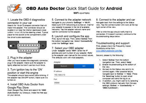
OBD Auto Doctor Quick Start Guide for A ndroidWIFI ADAPTERS1. Locate the OBD-II diagnostics connector in your carSearch for 16-pin D-shaped connector that will match the adapter. The connector should be located in or near the interior dashboard close (within 1 m or 3 ft) to the steering wheel. Typical place for the socket is the compartment under the driver's side dashboard.2. Plug in the adapterAfter you have located the diagnostic connector, plug in the adapter. Make sure the adapter is tightly attached but don’t use too much force. 3. Turn ignition key to the ‘ON’ position or start the engineThe adapter should have some LEDs blinking. If the adapter has ON/OFF switch, make sure it is turned on.4. Install OBD Auto Doctor from Google Play StoreOpen Google Play Store and search for ‘O BD Auto Doctor’ (by Creosys). Install the free app on your device. 5. Connect to the adapter networkNavigate to your phone’s ‘S ettings’ -> ‘W i-Fi’.Make sure Wi-Fi networking is turned on. Wait foryour adapter to appear in the list of availablenetworks. Tap the adapter network name andwait for connection to the adapter.6. Launch and configure the appFirst, launch the app. Then, select ‘E xtras’ fromthe bottom navigation bar. Select ‘C onnectivity’under the ‘S ettings’ label.7. Select your OBD adapterUnder ‘A dapter’ select ‘W iFi’. Enter the IPaddress and port number of your adapter. Referto the adapter user manual for the correct values.The defaults work with most adapters.8. Connect to the adapter and carNavigate back from the settings to the Statusview. Tap the connect button (link icon) at the topright corner of the view.After a while the app should notify that it isconnected. If it doesn’t connect, continue to thetroubleshooting steps below.Troubleshooting and supportFirst, please check the Frequently AskedQuestions online from/faq.Second, please try the following:1.Select ‘E xtras’ from the bottomnavigation bar. Then, select ‘H elp’.2.Enable troubleshooting at the bottom ofthe view.3.Go back to the Status view and try toconnect again. After possible failure,navigate back to ‘E xtras’ -> ‘H elp’. Pressthe ‘S end log’ button to open emailcomposer and send the log to us.4.In addition, you might want to try selectingthe OBD protocol manually from the appsettings (‘E xtras’ -> ‘C onnectivity’ ->‘O BD-II protocol’).。
bushound5.0全功能版
bushound5.0全功能版1.请下载安装bus hound 5.0全功能版2.安装完毕后请一定要重启,否则软件不能工作3.进行USB监控的主要步骤如下:(1)启动软件,讲USB设备插入USB口(2)在DEVICE内选择设备,例如我的设备是一个USB电话,则设备为USB COMPOSITE DEVICE,选中该设备,可以在下面的PROPERTIES 看到设备的总线类型,设备的电源以及各个端点的功能,在该设备下面还有两个分支:USB AUDIO DEVICE 和 "USB人体学输入设备"(这就是本设备占用的两个接口),一样在PROPERTIES里面可以看到他们的类代码为0x01和0x03.(3)在看完基本信息后,将上述的某个接口,或者全部打勾.(4)切换到"SETTING"选项卡,将MAX PHASE设置为512,这样你就可以看到完全的DESCRIPTOR和其他的数据了.(5)在"PHASE TO CAPTURE"里面的几个和USB相关的选项如下:CDB:命令描述符块;CTL:USB控制传输;DI/D数据输入/输出;LEN:数据长度;INSOC:同步传输;RSET:总线复位;URB:USB请求块;USTS:USB状态查看USB数据传输就把它们都打勾就行了;(6)在"Coloumn to display"里面,把里面的全部打勾,(为什么我就不说了).注意,这样要把窗体最大化才可以看见全部数据.(7)在"CAPTURE"选项卡里面可以看捕捉的数据了,在文本框输入文字,再点旁边的箭头,可以查询.按STOP,再按START可以清屏.(8)举个例子,接上设备,在文本框输入GET DESCRIPTOR(大小写无所谓),点箭头,可以找到你的DESCRIPTOR,但是值得注意的是这个DESCRIPTOR主要是CONFIG,如果是设备描述符会有专门的说明GET DEVICE DESCRIPTOR;这个软件好像不会捕捉STRING DESCRIPTOR.设备返回的信息在DI里面4.希望大家有好资料也告诉我一声,谢谢!5.最后祝大家都顺利开发出USB设备.。
2020年(VR虚拟现实)HDD-MDVR说明书V30(中文版)
(VR虚拟现实)HDD-MDVR说明书V30(中文版)车载HDD-MDVR 使用说明书(电子版)目录1注意事项52产品规格63前后板及录像机安装说明83.1前面板说明83.2后面板接口说明93.3接线说明103.3.1AV视音频输入线说明103.3.2电源线说明103.3.3I/O报警输入输出说明113.4录像机检查123.4.1开箱及附件检查123.4.2SD卡安装说明134遥控器使用说明144.1遥控器按键说明144.2软键盘输入说明165录像机使用操作说明175.1用户登录185.2直通预览界面195.3录像检索205.3.1详细文件及备份说明215.3.1录像回放说明225.4录像设置225.4.1帧率动态配置等说明225.4.2定时录像设置245.5功能设置265.5.1报警设置275.5.2云台设置305.5.3时间设置315.5.4存储设备管理325.5.5设备维护,系统升级说明335.5.6网络设置345.6系统信息375.7车辆信息385.7.1基本信息395.7.2速度设置395.7.3加速度设置405.7.4温度设置405.7.5开关机设置415.7.6无线设置425.7.7WIFI设置425.8显示设置435.9密码管理446FAQ461注意事项安装和使用之前,请一定详细阅读使用说明书,以便您能正确使用和保护您的机器。
本说明书前面部分为注意事项和安装使用介绍,请先行阅读。
➢注意事项●为保障您的权益,在安装使用本产品前,请仔细阅读本手册内容。
●本产品为车内使用设备,为了防止短路或电击危险,请勿将本机放在雨中或潮湿的环境中。
●万一任何固体或液体进入机箱内,请立即断开机器电源,并请有资格的技术人员检查后方可再启动。
●本产品属于高科技设备,机内几乎没有用户自己能够修理的原件部分。
发生故障时必须请有资格的技术人员来检修,或与经销商联系。
➢安装环境●本录像机使用直流12~36伏电源,在使用前必须确认当地的电源电压;●如果长期不使用机器,最好完全断开录像机电源;●请选择适当的安装位置,以便使空气能在机器周围自由流通,以防止机器过热;●机器不可安装在散热器、通风道等热源附近,或有直射阳光、过多尘埃、或会发生机械振动或冲击的地方。
途虎车联OBD车载定位器快速安装说明书
Smart OBD Car TrackerQuick Start Guide(Version 1.0)To ensure quickly and correctly use, please read this manual carefully before using. Any changes to the product appearance, color or accessories are without notice.1.FunctionsThis product supports the most types of car since 2007. Please login in to the platform that specified by the dealers to ensure that the model of your car is in the supported OBD car type list. If your car does not support the OBD, then it can be used as a GPS tracker.1.1 FunctionsCurrent Position Geo-fence Remote Diagnostics Fault ReminderVibration Alarm Displacement Alarm Track Playback1.2 ParametersGSM850/900/1800/1900Mhz, Quad-band is in common use all over the world.GPRS: Class 12, TCP/IPVoltage: 9-36VDCWorking current: ~9mA (12vDC)GPS Positioning time: Cold start -38s (open sky)Warm start -32sHot start -2s (open sky)GPS positioning accuracy: 10m (2DRMS)Working condition temperature: -20°C---70°CWorking condition humidity: 20%~80%Size: 86.6(L)*44.0(w)*13.6(H) mmWeight: 50.5g2. Appearance and installation instructions 2.1 Appearance3. Power on/off and installation guide3.1 Power on and installation① Push the cover downward② Push the sim card buckle to the right③ Open a sim card buckle upwardNote: SIM card needs to enable the GPRS function.④ Please push the battery switch ON⑤ Push the cover upward⑥ OBD Diagnostic Instrument connected with GPS tracker (note: pay attention to thedirection of the connector)⑦ Find out the OBD interface (usually at the bottom of the steering wheel)⑧ Insert OBD Diagnostic Instrument into vehicle OBD interface in the case that vehicleis engine off3.2 Power off① Pull out the OBD Diagnostic Instrument② Pull the cover downward③ Turn the battery switch OFF and pull out the OBD Diagnostic Instrument.4. Installation4.1 GPS tracker installation instructionsIt’s better to choose the dealers specified professional department or professions to install and test because this GPS tracker is a high-tech fleet management product.Installation positionNote:1. Please install the device upwards.2. If the windshield has been pasted by lagging and heating, it will reduce GPS signals and resulting in abnormal GPS work, so please change GPS tracker installation position.5. LED indicators definition5.1 GPS tracker LED working status (non-dormant state)5.1.1 Red LED (power/working status)5.1.2 Blue LED (GPS signal status)5.1.3 Green LED (GSM signal status)5.2 Arm status indicatorsBlue, red, green LED lights flashing circular signify that arm status is started.6. Devices application operation6.1 Login to supplier specified online tracking platform to set up and operation6.2 Please login to the dealers specified website to download APP to install.7. Appendix7.1 Battery safety●Please use battery that the original factory specified and use any otheraccessories will void the warranty. If use others accessories leading theGPS tracker damaged, we won’t assume any warranty responsibility.●Please avoid the metal objects leads the battery contactors short-circuit.●Please do not bend or forced open the battery.●Please do not immerse the battery in water or on the fire. Batteries have tobe recharged at closed room temperature. If the temperature is below 0℃or 45℃,the battery won’t to be charged.●It’s forbid to use the battery that have deformation appearance, off-color,leakage or damaged complete package.7.2 TroubleshootingIf find anything that is abnormal during the operation, please refer to the following problems and solutions. If the problem still can’t be solved, please contact the dealers or service provider.ShenZhen Concox Information Technology CO.,LtdTel: +86 755 2912 1200Fax: +86 755 2912 1290E-mail:*************** Add: 4/F, Building B, Gaoxinqi Industrial Park, Liuxian 1st Road, No.67 Bao'an District, Shenzhen。
车载安装使用说明(共25张PPT)

安装使用说明
22
ACCESS POWER
四、DS-1002HM车载备份仪
2、硬件接口
1
2 3
(1)、5英寸彩色液晶显示屏; (2)、硬盘读写指示灯(有数据读写时闪烁); (3)、POWER 电源指示灯;
(4)、DC 12V直流电源输入接口; (5)、SATA数据备份接口;
(6)、USB接口; (7)、视频输入接口。
红外接收口
CH1
POWER
CH2
READY
CH3
STATUS
CH4
LINK
TX/RX
HDD
MODEM
ALARM
安装使用说明
20
三、注意事项 7、后接口板定义
SW
DC OUT +12V G +12V G +5V G
DC IN
KEY
+ +- - +-
RS-232
eSATA UTP
VGA
ANT
ALARM IN
ALARM OUT
RS-485
G G 1 2 3 4 1A 1B 2A 2B T+ T- R+ R-
KB
LINE IN
VOUT
VIN1
VIN2
VIN3
VIN4
AOUT
AIN1AIN2来自AIN3AIN4安装使用说明
21
四、DS-1002HM车载备份仪
1、功能 DS-1002HM是一款用来对DS- 8000HM的录像资料进行高速备份的专用设 备,接口灵活、备份速度快,可通过遥控器 和液晶屏进行操作。 通过USB/SATA等接口和计算机连接,可 导出或浏览录像资料。
车载安装使用 说明
HuddleCamHD Pro USB 3.0 EPTZ 摄像头安装与操作手册说明书
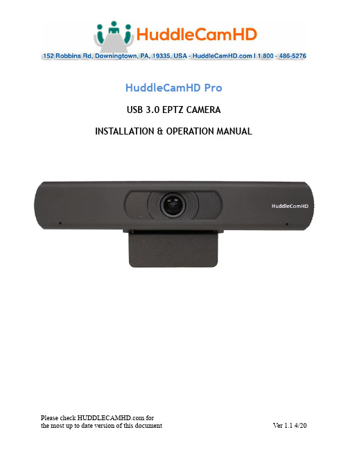
HuddleCamHD ProUSB 3.0 EPTZ CAMERA INSTALLATION & OPERATION MANUALPrecautions…………………………………………………………………………………………. Safety Tips…………………………………………………………………………………………………………….•Please read this manual carefully before using the camera.•Avoid damage from stress, violent vibration or liquid intrusion during transportation, storage or installation.•Take care of the camera during installation to prevent damage to the camera case, ports, or lens.•Do not apply excessive voltage. (Use only the specified voltage.) Otherwise, you may experience electrical shock.•Keep the camera away from strong electromagnetic sources.•Do not aim the camera at bright light sources (e.g. bright lights, the sun, etc.) for extended periods of time.•Do not clean the camera with any active chemicals or corrosive detergents.•Do not disassemble the camera or any of the camera's components. If problems arise, please contact your authorized dealer.•Contact your authorized dealer for repair.In the Box…………………………………………………………………………………………….Supplied Equipment………………………………………………………………………………….•HC-EPTZ-USB Camera (1)•USB 3.0 A-B cable (1)•IR Remote Controller (1)•User Manual (1)Physical Description………………………………………………………………………………1. Front View………………………………………………………………………………………….1. Lens108° Field of View lens2. Power LEDBlue LED lights when unit is powered and on.3. Mounting BaseMounting base for camera. 1/4-20 mounting screw.4. Microphone ArrayBeamforming microphone array2. Rear View………………………………………………………………………………………………………….5. HDMI ConnectionHDMI 1.4 (4K@30) connection to display6. USB 3.0 ConnectionFor connecting to PC for video and powerOSD MENU………………………………………………………………………………………………On Screen Display MenuUse the OSD menu to access and change the camera’s settings.Note: Electronic P/T/Z functionality is disabled when the OSD menu is displayed.The camera OSD Menu offers the following settings options:•Exposureo Full Auto▪ExpCompMode On / Off▪Exp Comp-7 ~ +7Note: Only available when ExpCompMode is “On”▪Gain Limit0 ~ 15▪Backlight On / Off▪DRC Strength0 ~ 8▪Anti-Flicker Off / 50Hz / 60Hzo Shutter Priority▪Shutter1/30s, 1/60s, 1/90s, 1/100s, 1/125s, 1/200s,1/250s, 1/350s, 1/500s, 1/725s, 1/1000s,1/1500s, 1/2000s, 1/3000s, 1/4000s,1/6000s, & 1/10000s▪DRC Strength0 ~ 8o Bright▪Bright0 ~ 17▪Gain Limit0 ~ 15▪DRC Strength0 ~ 8▪Anti-Flicker Off / 50Hz / 60Hz•Coloro Auto▪AWB Sens Low / Middle / High▪RG Tuning-10 ~ +10▪BG Tuning-10 ~ +10▪Saturation60% ~ 200%▪Hue0 – 14o Indoor▪Saturation60% ~ 200%▪Hue0 ~ 14o Outdoor▪Saturation60% ~ 200%▪Hue0 ~ 14o OnePush▪AWB Sens High / Low / Normal▪RG Tuning-10 ~ +10▪BG Tuning-10 ~ +10▪Saturation60% ~ 200%▪Hue0 ~ 14o Manual▪RG Tuning0 ~ 255▪BG Tuning0 ~ 255▪Saturation60% ~ 200%▪Hue0 ~ 14o V AR▪Color Temp2500K ~ 8000K▪RG Tuning-10 ~ +10▪BG Tuning-10 ~ +10▪Saturation60% - 200%▪Hue0 ~ 14•Image▪Luminance0 ~ 14▪Contrast0 ~ 14▪Sharpness Auto / 0 ~ 15▪Flip-H Off / On▪Flip-V Off / On▪Gamma Default / 0.45 / 0.5 / 0.56 / 0.63▪Style Clarity / Bright / PC / Clarity (LED) / Norm▪LDC Off /-10 ~ +10•Noise Reduction▪2D-NR Close / Auto / 1 ~ 5▪3D-NR Close / 1 ~ 8•Setting▪Language English, Chinese, French▪EPTZ On / Off▪Zoom Limit1x-3x / 1x-4x / 1x-8x / 2x-4x / 2x-8x / 3x-8x▪DVI Mode DVI / HDMI▪HDMI Format1080p30 / 1080i60, 1080i50, 4K@30▪Auto Framing On / Off▪H264 Enable On / Off *▪Audio Enable On / Off *•*Requires power cycle•Information Displays current camera settings •Restore Default Restore camera default settingsIR Remote Controller……………………………………………………………………………Note: IR Remote will not work on other HuddleCamHD cameras1.Standby Button:Press this button to enter standby mode. Press it again to enter normal mode.NOTE: Power consumption in standby mode isapproximately half of the normal mode.2.Position Buttons:T o set preset or call preset3.* Button:For multiple functions.4.Preset ButtonAllows for setting a presetNOTE: [PRESET] + Numeric button (0–9) to set5.Home ButtonsPress the Home button to send the camera back to front6.Return ButtonPress the button to back previous menu7.Zoom ButtonsZoom+: Zoom In (Slow and fast speed)Zoom-: Zoom Out (Slow and fast speed)8.L/R Set ButtonSet the left & right direction of the remote control.(not available on this model)9.Focus ButtonsUsed for focus adjustmentPress AUTO to adjust the focus on the center of theobject automatically. T o adjust the focus manually, pressthe MANUAL button, and adjust it with FAR and NEAR.10.Camera Address Select ButtonsCamera the button corresponding to the camera whichyou want to operate with the remote controller11.# ButtonFor multiple functions12.Multiple function ButtonsFunction 1. Set camera IR addressPress 3 keys contiguously can set camera IR address asfollow:[*] + [#] + [F1]: IR Address 1[*] + [#] + [F2]: IR Address 2[*] + [#] + [F3]: IR Address 3[*] + [#] + [F4]: IR Address 4Function 2. Image freezing functionPress [F4] to start the freeze function. The word“Freeze” displays on the upper left corner. After fiveseconds, the display disappears automatically (thoughthe freeze feature continues). T o cancel the freeze, press the [F4] key the word “Unfreeze” displays on the upper left corner. After five seconds, the display disappears automatically.13.Reset ButtonClear preset: Erase a preset position [RESET] + numeric button (0-9), or: [*] + [#] + [RESET]: Erase all presets 14.Pan/Tilt Control ButtonsAllows for Electronic Pan/Tilt control (Note you must digitally zoom before electronic P / T is available)15.Menu ButtonsMenu Button: Press this button to enter or exit the OSD menu.16.Backlight ButtonBacklight button: Press this button to enable the backlight compensation. Pres it again to disable the backlightcompensation.NOTE: Only available in manual exposure mode.NOTE: If there is a light begin the subject, the subject will appear dark. In this case, press the backlight ON/OFF button. T o cancel the function, press the backlight ON/OFF button17.P/T RST ButtonPress this button to self-calibrate pan & tilt once again.NOTE: not available on this model[*] + [#] + [1]: Display OSD menu in English[*] + [#] + [3]: Display OSD menu in Chinese[*] + [#] + [6]: Quickly restore the default settings[*] + [#] + [8]: Show the camera version[*] + [#] + [9]: Quickly set mount mode (flip/normal)Connection Instructions………………………………………………………………………1.Connect included USB 3.0 cable to camera and USB 3.0 port of PC.2.Wait for camera to power on.3.Select and configure camera in your software of choice.NOTE: Failure to follow this sequence may result in no connection to PC.Care Of The Unit………………………………………………………………………………….Remove dust or dirt on the surface of the lens with a blower (commercially available). Installation Instructions………………………………………………………………………Monitor Installation…………………………………………………………………………………….When mounting the HuddleCamHD camera on a monitor, ensure that the mount screw is fastened tightly to the camera. Use the top mount to rest the camera on amonitor. Position the bottom mount on the back of the monitor to secure the camera in position. You can rotate the camera lens as necessary.Tripod Installation………………………………………………………………………………………When using the HuddleCamHD camera with a tripod, screw the tripod to the bottom of the camera.The tripod screw must fit shown specifications:Troubleshooting………….…………………………………………………………………………Important Notes Regarding USB Connectivity:USB 3.0 ports are backwards compatible with USB 2.0 devices. USB 2.0 ports are not completely forward compatible with USB 3.0 devices (some USB 3.0 devices willconnect to USB 2.0 with limited functionality).External USB hubs should be avoided (i.e. give the camera its own USB port on thedevice) as they are not well suited to transmitted HD video reliably.USB extension systems must be fully compatible with the version of the USB that you are using and must utilize an external power supply, when required. Caution: Some “Compatible” USB 3.0 extenders do not actually have the full 5Gbps bandwidthrequired for uncompressed HD video – so check bandwidth specs.Always connect the HuddleCamHD camera directly to the device in order to associate the UVC drivers before attempting to use any extension system.USB 3.0 power saving settings in the devices operating system should be turned off completely for reliable USB camera connectivity.HuddleCamHD CamerasAll HuddleCamHD camera utilize the UVC (USB Video Class) drivers that are built into Windows, Mac OSD and Linux to stream HD video to your device via your device’s USB port (USB 2.0 or 3.0 depending upon the HuddleCamHD model).When your device successfully recognizes the camera, your device will register the HuddleCamHD camera as an “imaging device”.You can see this in your Windows Device Manager program (type “device manager”into the Windows search tool) as shown in the screenshot, below:In this example, you can see the HuddleCamHD model in use connected as a fullyfunctional USB 3.0 device (HuddleCamHD) as well as a USB 2.0 device with limitedfunctionality (USB2.0 Camera).If your device has not connected to or has not recognized the HuddleCamHD camera as an imaging device, try reconnecting the camera via USB (USB 2.0 or USB 3.0depending upon HuddleCamHD model). If the camera still does not operate properly, please contact HuddleCamHD support at *********************** for furtherassistance.Similarly, you can see a connected device in System Information on a Apple computer. See screenshot below:In this example, you can see the HuddleCamHD model in use connected as a fully functional USB 3.0 device “HuddleCamHD” as well as a “USB2.0 camera” with limited functionality (USB2.0 camera).Specs………………………………………………………………………………………………………Model Number: HC-EPTZ-USBCamera & Lens•Video CMOS Sensor1/2.5” CMOS 8.51M Mega Pixel•Resolution3840x2160, 1920x1080, 1280x720, 1024x576, 960x540,640x480, 640x360•Frame Rate50Hz: 1 ~ 2560Hz: 1 ~ 30•Zoom8X Digital Zoom•Focal Length f=2.8mm•Field of View108°•Min Lux0.05 Lux (@ F1.8, AGC ON)•Warranty 3 years parts and laborRear Board Connectors•Video Interface USB 3.0, HDMI 1.4USB 2.0 with reduced quality•Power Supply Interface USB 3.0•Working Environment IndoorPhysical•Material Aluminum, Plastic•Dimensions7.63”W x 2.36”H x 3.66”D(194mm x 60mm x 93mm)•Weight0.7 lbs (0.34 kg)•Box Dimensions9.375” x 4.3125” x 4.625” (238mm x 109.5mm x 117.5mm)•Boxed Weight 2.4 lbs (1.1 kg)•Color Black•Operating Temperature32°F to +113°F (0°C to +45°C)•Storage Temperature-14°F to 140°F (-10°C +60°C)•Working Environment Indoor only。
c500hub抬头显示说明书
c500hub抬头显示说明书c500hub抬头显示通过中控显示屏进行设置。
在中控屏幕先点击设置,然后点击我的汽车,里面有个显示选项,点进去,有“平行显示”四个字,这一就是抬头显示的设置;可以设置打开或关闭,也可以设置显示哪些功能。
例如车速信息、测速路段提醒、导航等等,打上勾就显示,不打勾就不显示;抬头显示简称HUD,又叫作平视显示器。
通过光学反射原理,使至关重要的知识投射在玻璃上,不用行驶员低头观察。
HUD抬头显示仪,原是军用飞机上的显示系统。
飞行员不必低头,就能在风窗上看到所需的重要信息。
目前,一些高级汽车把它移植到汽车上来。
主要功能:1.卫星获取速度,准确,及时,权威。
2.超速报警,可以设置报警速度值。
3.行驶里程统计,车停即自动显示本次行驶里程统计(MAX 999里)。
4.行驶时间统计,车停即自动显示本次驾驶时间统计(MAX 999)5.疲劳驾驶报警,连续行驶时间每隔一小时报警提示一次。
产品特点:1.开车更安全.视力脱离主方向时间减少99%,眼球微度动即可捕速度信息。
2.开车更轻松减少视距调节频,眼球方向调节强度,减少眼疲劳3.乘客更舒心速度信息公示,提高了乘车安全感和舒适度。
出租车和专车必备。
4.多模式显示夏季烈日或者夜间,均可选择不同的安装位置,清晰显示速度值。
5.安装简单可以外接5 V"12V直流电源,外接小功率移动电源也可以正常工作。
6.计量单位切换可以对速度计量单位(公里/英里)快速切换,满足不同市场的需求。
7.智能显示亮度控制强光下,速度显示亮度自动增加。
弱光下,显示亮度自动减弱。
HONDA 摩托车 应用程序安装说明书
1 of 2
PIVOT BOLT
SIDESTAND (Save)
87967-MKC-A000.indd
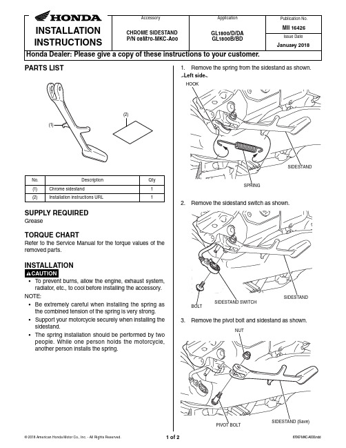
4. Apply grease to the positions shown.
GREASE Apply.
CHROME SIDESTAND
5. Install the chrome sidestand, sidestand switch and spring in the reverse order of removal.
2 of 2
1
(2)
Installation instructions URL
பைடு நூலகம்
1
SUPPLY REQUIRED
Grease
TORQUE CHART
Refer to the Service Manual for the torque values of the removed parts.
INSTALLATION
Publication No.
MII 16426
Issue Date
January 2018
PARTS LIST
1. Remove the spring from the sidestand as shown. <Left side>
HOOK
(2) (1)
No.
Description
Qty
(1)
Chrome sidestand
Accessory
Application
INSTALLATION INSTRUCTIONS
CHROME SIDESTAND P/N 08M70-MKC-A00
GL1800/D/DA GL1800B/BD
- 1、下载文档前请自行甄别文档内容的完整性,平台不提供额外的编辑、内容补充、找答案等附加服务。
- 2、"仅部分预览"的文档,不可在线预览部分如存在完整性等问题,可反馈申请退款(可完整预览的文档不适用该条件!)。
- 3、如文档侵犯您的权益,请联系客服反馈,我们会尽快为您处理(人工客服工作时间:9:00-18:30)。
行车电脑Hobd软件安装使用说明
1.将压缩包解压后将Navngo文件夹复制到SDMMC卡根目。
注:此文件夹是在渝F-纯
属误会制作的仿WIN8外置卡破解版本为2013款卡罗拉原版的文件的基础上将启动图吧的程序改为启动行车电脑,本人只是出于DIY目的,最终版权归原作者所有,请不要用于商业目的。
2.将行车电脑软件压缩包解压到SDMMC卡hobd文件夹中
3.将卡放入导航,按电源按5秒,重启后按“行车电脑图标”启动hobd.
4.进入hobd界面后,按右下显示----设置再按OBD端口设置
5.进行OBD端口设置界面后ELM接口处选最后的第一次进入的时候是OBD 之后就变
成一串数字,这里需要耐心等待一下下拉框才能有反应。
蓝牙密码处写1234,要用到右下角的键盘,点的时候要注意要点先偏下方一些,不然分很难点选到自己想要的数字。
其它的不用管它,如果第4项显示蓝牙已连接证明已经连接成功,如果显示搜索蓝牙就要
耐等待一下,或者检查一下OBD有没有接好,接好时有蓝色的灯闪烁。
6.接着进行车辆设置,第一项不用管它,第二项制造商选TOYOTA 第3项选择如图
7. 选完后点更新,右上角可以安关闭回到设置界面再按右上角X 关闭,这时界面会回到“概
述” 会显示转速、温度等信息,向左拔就会到行车电脑界面如果操作不顺可以接USB 鼠标,但不会显示鼠标指针,按住左键往左拔就是。
8. 其它的选项大家去探讨一下吧,有新发现寄得发到群里给大家共享一下。
9. 最后感谢渝F -纯属误会制作的仿WIN8外置卡破解 此程序已经非常稳定,安装操作方
便,比原来用DSA+导航占用资源少,值得使用。
另外再提点建议:1外置卡破解一般不会使用原车的美行导航,原车的导航升级麻烦,建议改成外置美行。
2界面的导航太多了,一般有凯立德、道道通、美行+DSA 已经足够,其它的导航还是改用其它一些实用的程序吧,进入WINCE 的程序挺不错。
