S5802带限流 三合一5V 1 A输入输出
OC5806L
静电耐压值(人体模型)
2000
V
注 1:极限参数是指超过上表中规定的工作范围可能会导致器件损坏。而工作在以上极限条件下可能会影响器 件的可靠性。
OC5806L_V1.0
3 of 8
OC5806L
内置 150V/3A MOS 宽输入电压降压型 DC-DC
电特性(除非特别说明,VDD =12V,TA =25oC)
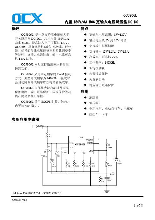
典型应用电路图
宽输入电压范围:8V~120V 输出电压从 5V 到 30V 可调 支持输出恒压恒流 支持输出 12V/1.5A,5V/1.8A 高效率:可高达 95% 工作频率:140KHz 低待机功耗 内置过温保护 内置软启动 内置输出短路保护
应用
追踪器 恒压源, 电动汽车、电动自行车、电瓶车 扭扭车、卡车
输出反馈电压正端采样 输出反馈电压负端采样 内部 5V LDO 输出,接电容。
芯片地 电感电流检测脚 内置 MOS 源极 内置接 VIN 脚
OC5806L_V1.0
2 of 8
内部电路方框图
OC5806L 内置 150V/3A MOS 宽输入电压降压型 DC-DC
极限参数(注 1)
符号
描述
参数范围 单位
II(A)
VO
IO
0.395 12.17
0.271 12.13
0.184 12.10
0.14 0.113
12.09 12.12
0.5
0.095 12.07
0.086 12.05
0.069 12.02
II(A)
VO
IO
0.8
12.16
0.54
12.10
0.364 12.09
屹晶 EG1163 芯片数据手册说明书

2. 描述
ELECTRONIC GIANT
EG1163 芯片用户手册
高压大电流降压型开关电源芯片
2018 © 屹晶微电子有限公司 版权所有
REV 1.0
屹晶微电子有限公司
EG1163 芯片数据手册 V1.0
高压大电流降压型开关电源芯片
版本变更记录
版本号 日期
描述
V1.0
2018 年 05 月 15 日 EG1163 数据手册初稿
2018 © 屹晶微电子有限公司 版权所有
1/1
屹晶微电子有限公司
EG1163 芯片数据手册 V1.0
高压大电流降压型开关电源芯片
EG1163 芯片数据手册 V1.0
1. 特性
同步续流方案,支持高压大电流方案。 外接一个电容可设置工作频率(0-300KHz) UVLO 欠压锁定功能:
2018 © 屹晶微电子有限公司 版权所有
1/10
屹晶微电子有限公司
4. 引脚
4.1 引脚定义
EG1163 芯片数据手册 V1.0
高压大电流降压型开关电源芯片
图 4-1. EG1163 管脚定义
2018 © 屹晶微电子有限公司 版权所有
2/10
屹晶微电子有限公司
EG1163 芯片数据手册 V1.0
高压大电流降压型开关电源芯片
4.2 引脚描述
引脚序号 引脚名称
1
HS100M2-N30A说明书
HS100M2-N30A说明书武汉SolyHS100M2-N30A说明书简介1.产品特点该产品是由武汉SOly推出HS100M2-N30A系列的隔离增强型电源产品,具有轻量便携,低噪音,低温升,高可靠性,高功率密度等特点。
2.产品参数2.1 技术参数a)输入电压:90~264Vac,标准47~63Hz,或按用户要求特殊处理;b)额定输出功率:100W;c)温度宽度:输入电压范围90~264Vac,温度范围-20℃~+70℃。
2.2 输出特性a)输出参数:DC5V-24V可调,其单路最大电流为20A;b)精度:±1%;c)纹波噪声:≤75mV;d)建立时间:≤50oMs;e)满载效率:≥82%;f)反激式调节:花样联动调节传输时间≤1μs;g)热关断:100小时内输出电压不稳定,精度超过额定值,则加热关断,未恢复正常,待温度降至正常后,则重新启动电源3.安全及认证该电源产品具有欧盟EN60950-1安全认证,符合ROHS污染限制标准,可以在全球符合安全标准的环境下使用。
4.产品应用隔离增强型电源可以用于特种设备,医疗设备,工业系统,计算机及其它电子产品,网络产品等安全场所,保证其安全性。
5.使用须知(1)应选择气象条件较好的无尘车间使用,温度-20℃~+70℃,湿度≤95%,非冷凝状态;(2)安装时,使用前必须先检查是否符合规格,检查电源连接工具是否正确;(3)禁止非有资质的技术人员私自拆卸,调试或接线设备;(4)设备应随时检查,并定期做维护保养;(5)在使用过程中,应随时关注电源输出功率,最高不可超出额定功率;(6)在使用的过程中,应杜绝水管、湿毡、水箱放在电源旁边等有潮湿因素的情况;(7)如果电源产生异常,需要停止电源工作电源马上断开连接,并停止使用;6.维修和保养(1)定期检查电源连接、清扫内外灰尘;(2)定期检查电缆接口、温升等;(3)检查电枢是否异常,如发现有热灯明显变亮,应立即停止使用;(4)补充润滑油,检查柱塞是否异常;(5)定期检查是否产生异常杂音,如发现磁铁夹紧固定不牢、活动部件受到隔离(如水箱)的干扰等;7.保修如正常使用并符合说明书规定,我们提供一年保修服务,保修期间出现故障,我们将免费检修或更换。
上海飞轩电子有限公司 FS2010 产品说明书

特点:�宽输入电压范围3.6V-18V�输出可调范围1.222V-16V�最大占空比100%�最小饱和压降0.6V�380KHz固定开关频率�2A电流输出能力�内部优化功率管设计�高效益�极好的线性输出且负载可调�TTL关断能力�内建频率补偿,热关断功能,限流功能,短路保护功能�可选封装形式:SOIC-8应用领域:�手持式DVD�LCD监控器�数码像框�机顶盒�调制解调器�通信/网络设备概述FS2010是一个380KHz固定频率脉宽调制(降压型)DC/DC转换器。
具有2A负载驱动能力并且效率高,低纹波和极好的线性,负载调节能力好,仅需最少外部元。
可调输出使用简单,内建频率补偿和固定频率震荡器。
脉宽调制控制电路可以线性调节占空比从0到100%。
具有使能功能,内置过流和短路保护功能,当发生过流和短路保护时,FS2010工作频率将从380KHz降到80KHz。
内置频率补偿模块使FS2010外部元件最少。
图1.FS2010封装类型引脚设置图2.FS2010引脚结构(顶视图)表格1引脚描述功能模块图3:FS2010功能块方框图引脚数引脚名描述1,6,8NC 空脚(第8脚为测试脚,在系统应用时,第8脚必须悬空。
)2VIN 电压输入引脚,FS2010工作在直流电压3.6V 到18V,输入外接适合大的旁路电容到地来消除输入噪声。
3SW 功率开关输出引脚(SW ).输出端是提供功率输出的开关结点。
4GND接地引脚,做版图时必须小心。
此引脚必须放置在硝特基二极管和输出电容到地的外面,来阻止电感电压引起的开关电流毛刺输入到FS2010。
5FB 反馈引脚(FB ),通过外部电阻来分割回路,反馈是来检测和调节输出电压,反馈端电压是1.222V 。
7EN使能引脚。
驱动ON/OFF 引脚为低电平则开启设备,驱动此引脚为高电平则关断设备。
典型应用电路图4.FS2010典型应用电路12V-5V/2A 系统效率曲线订购信息最大额定值(注释1)注释1:工作在列表的最大额定值以上会造成器件永久损坏。
5V转3.3V,3V,2.8V,1.8V降压2A芯片电路-PW2051

PW2051 是一款由基准电压源、振荡电路、比较器、 PWM/PFM 控制电路等构成的 CMOS 降压型 DC/DC 调整器。
利用 PWM/PFM 自动切换控制电路达到可调占空比,具有全输入电压范围内的低纹波、高效率和大输出电流等特点。
PW2051 内置功率 MOSFET,集成了过压、过流、过热、 短路等诸多保护电路,在超过控制值时会自动断开,以保护芯片。
本产品结合了微型封装和低消耗电流等特点,最适合在移动设备的电源内部使用。
PW2051采用SOT23-5L封装配合较少的外围原件使其非常适用于便携式产品.产品特点●最大效率可达 95%●最大输出电流 1.5A●超低静态电流 40μA●甚小输出纹波 <±0.4%●低压操作 可达 100%占空比●PWM/PFM 自动切换 占空比自动可调以保持全负载范围内的高效率、低纹波●短路保护应用范围●数码相机、电子记事本、 PDA 等移动设备电源●照相机、视频设备、通信设备的稳压电源●微机电源●机顶盒典型应用电路C1为可选电容引脚配置/说明引脚号符号 引脚说明 1CE 芯片使能端,高有效 2GND 地 3LX 内部功率开关输出端口 4VIN 电源输入端 5 FB 输出电压反馈端绝对最大额定值 项目符号 绝对最大额定值 单位 输入电压VIN -0.3~6.5V 输出电压VFB -0.3~6.5 V VLX -0.3~VIN + 0.3 V CE 端电压VCE -0.3~VIN + 0.3 V LX 端电流ILX ±2 A 容许功耗Pd 250 mW 工作环境温度Topr -40~+85 ℃ 保存温度 Tstg -55~+125 ℃CE GND LX FB SOT-23-5L (TOP VIEW)VIN 12345PCB 布局为了使噪音最低和操作性能最佳, PCB 布局时以下几点建议可作为参考:1、 VIN、 LX 、 GND 组成的功率通路,尽量采用短而宽的布线,避免过孔。
NE6032移动电源单芯片三合一方案介绍

NE6032移动电源单芯片三合一方案介绍NE6032是一款高性能、高可靠性的移动电源单芯片三合一方案。
它集成了电池管理、DC-DC变换和USB充电功能,并且支持USB快速充电、适配器充电和手动充电等多种充电方式。
下面将从方案特点、技术参数、应用场景和优势等方面进行介绍。
方案特点:1.移动电源单芯片三合一,简化了设计。
2.高度集成,减小了PCB板面积和系统成本。
3.支持多种充电方式,满足不同用户需求。
4.内置高精度ADC,实时监测电池电压和电流。
5.高效的DC-DC变换,提高了能量利用率。
6.低静态功耗,延长了电池使用寿命。
技术参数:1.输入电压范围:4.35V~5.5V。
2.输出电压范围:4.3V~5.25V。
3.输出电流:最大2A。
4.效率:高达90%。
5.充电方式:USB快速充电、适配器充电、手动充电。
6.温度范围:-40℃~85℃。
应用场景:优势:1.高度集成的单芯片设计,简化了电源电路的设计与布局,加快了产品的开发周期。
2.支持多种充电方式,满足用户不同的使用需求,提高了产品的灵活性和实用性。
3.高效的DC-DC变换,提高了能量的利用效率,延长了电池的使用时间。
4.内置高精度ADC,实时监测电池状态,为用户提供准确的电量信息。
5.低静态功耗,延长了电池的使用寿命,减少了充电次数。
总结:NE6032移动电源单芯片三合一方案是一款高性能、高可靠性的移动电源方案。
它通过集成电池管理、DC-DC变换和USB充电功能,满足了不同用户的需求。
该方案具有高效、稳定、灵活等优势,适用于各种移动设备的电源供应。
它的推出将为移动电源行业的发展带来新的机遇和挑战。
P系列伺服简易手册

3.4 电机附机械式刹车接线说明 .......................................................................................... 10 3.5 接口电路原理 ...................................................................................................................11
本手册的结构
请根据使用目的阅读必要的章节。 序号 第1章 第2章 第3章 第4章 第5章 第6章 第7章 附录 章 节 开箱注意事项 安装 配线连接 显示与操作 参数定义与功能 调试运行 报警及处理 电机代码表 ▲ 机型及外围 装备的选型 ▲ ▲ ▲ ▲ ▲ ▲ ▲ ▲ ▲ ▲ ▲ ▲ ▲ ▲ ▲ ▲ ▲ ▲ 额定值 及配线 系统 设计 安装及 配线 试运行 及调整 检查及 维护
PL5802原版芯片规格书
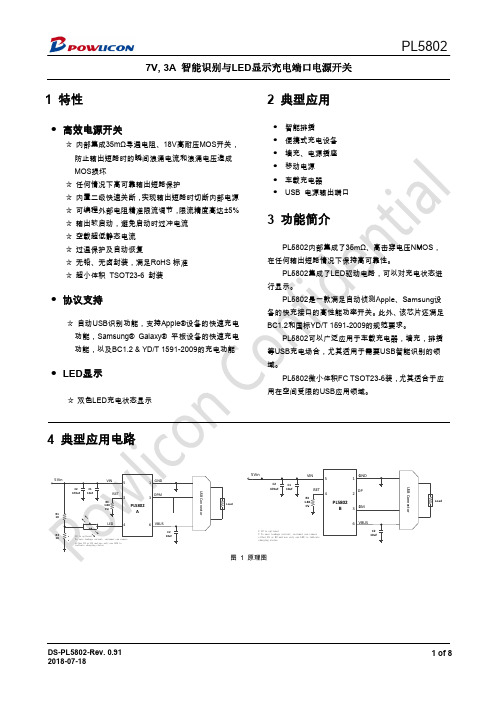
7V, 3A1 特性● 高效电源开关☆ 内部集成35m Ω导通电阻、18V 高耐A 智能识别与LED 显示充电端口电源开关高耐压MOS 开关, 2 典型应用● 智能排插 ● 便携式充电设备 PL5802 深圳芯派科技TEL:135 3045 2646 (唐生)ICQ:294 434 3362ICQ:294 435 33625 引脚定义及功能6 订单信息7.4 温度特性(注 3)注:4) 设计参数保证,批量生产不测试。
8 应用指南8.1 概述将输出电流降低到几微安。
PL58028.5 温度保护PL5802具有温度保护功能,通过内部温运行,芯片温度高于设定OTP阈值时,PL59 应用和设计9.1 输入输出电容输入输出电容提升了芯片的应用品质,或者更大的陶瓷旁路电容连接于Vin和GND 解电容吸收输入尖峰浪涌电压。
我们建议所有应用都应在输出加上至少10 PCB 布局11.1 布板指南1. PL5802 摆放。
将PL5802放置于靠近USB的输出控制器,2. 输入旁路电容在VIN的PIN附近放置10uF的陶瓷旁路电容需要另外一个470uF电解电容来吸收热插拔11.2 PCB布局实例内部温度检测电路,侦测工作时候的功率开关温度。
当设备PL5802将关闭电源开关,温度降低前,电源开关将不会被打品质,电容的选取需要根据实际应用进行优化,对于所有的应用GND之间,当输入电源存在热插拔操作时,可能需要更大的上至少4.7uF或者更大的陶瓷旁路电容,应用减少瞬态大电流对制器,最好在VBUS端增加一个10μF 的滤波电容。
路电容,使PCB中VIN的OIN脚到电容的距离尽可能短。
在存热插拔引起的输入电压尖峰。
Fig. 3 布板实例当设备在过流状态下以恒流模式会被打开,直到接触过温状态。
的应用场合,我们建议将4.7uF 更大的输入电容,例如470uF电电流对电源开关的影响。
在存在热插拔操作时,可能还序号 元件名称 元件编号1 贴片电容 C1, C2 贴片电阻 R1,3 贴片电阻 R34 贴片IC U15 黄色LED灯 LED6 红色LED灯 LED27 USB序号 元件名称 元件编号1 贴片电容 C1, C3 贴片电阻 R34 贴片IC U16 USB PL5802A BOM清单件编号 元件规格 封装 C1, C2 10uF/10V 1206 R2 1K 5% 0603 R3 2.2K 1% 0603 U1 PL5802A TSOT23-6 LED1 0603 LED2 0603单口USBPL5802B BOM清单件编号 元件规格 封装 C1, C2 10uF/10V 1206 R3 2.2K 1% 0603 U1 PL5802B TSOT23-6单口USB 数量 2 2 1 1 1 1 1数量 2 1 1 112 封装信息宝砾公司对本文件中可能出现的任何错误不公司不承担因应用或使用本协议所述的任何产品首席执行官书面批准,不得被作为生命维持设备偿。
5V2A电源适配器参数附图

5V2A电源适配器属性
联运达5V2A电源适配器<产品优势>
1.宽压输入100-240V,最大:90-264V,可供世界各国使用。
2.具有短路,过载,过流保护功能,使用更安全。
3.100%满负载测试,性能稳定。
4.绝缘性能好,抗电强度高。
5.抗干扰强度好,可靠性能高。
6.开关电源性能直流纹波小,工作效率高,节能环保。
7.产品通过国际安规认证要求。
5V2A电源适配器<产品参数>
额定输入:100-240VAC 50/60Hz Max:90-264VAC 47/63Hz
额定输出:5VDC5%
额定电流:2A
额定功率:10W
文波及噪声:120mV
短路保护:间隔式断开,快速恢复。
过流保护:130%-150%
过压保护:115%--135%
工作温度:-10-50℃
工作湿度:20%-90%RH
储存温度:-40-80℃
耐压测试:输入对输出:3KV AC 输入对接地:3KV AC
绝缘抗阻:100M ohms
连接器:DC接口2.1×5.5×11(可按要求定做)
DC 线材:1.2M (可按要求定做)
具有短路,过载,过流保护功能,使用更安全
100满负载测试,性能稳定
供应规格:中规,美规,英规,欧规,韩规,澳规,日规等(根据需求定制)。
cxa1191s电路参数
cxa1191s电路参数cxa1191s是一种常用的电源管理芯片,广泛应用于各种电子设备中。
为了保证cxa1191s的正常工作,需要正确设置其电路参数。
本文将介绍cxa1191s的电路参数及其设置方法。
cxa1191s是一款双路输出电源管理芯片,其输入电压范围为4.5V 至24V,输出电压可调,输出电流可达5A。
其主要参数如下:1.输入电压范围:4.5V至24V;2.输出电压范围:DC3.0V至24V;3.输出电流:最大5A;4.输出电压分辨率:0.1V;5.内部保护电路:过流保护、过温保护等。
cxa1191s需要与外部元器件组成电源电路。
其电路连接方式如下:1.输入端:连接电源的输入端子;2.输出端:分别连接两个输出电容和用电器的正极;3.反馈端:连接一个精密电阻,再通过采样线连接到控制器或微处理器,用于调节输出电压。
cxa1191s的电路参数包括输出电压、输出电流、反馈电阻值等,这些参数的设置将直接影响电源电路的工作状态。
以下为设置方法:1.输出电压设置:通过调节反馈端的精密电阻值来实现。
电阻值越大,输出电压越低;反之,输出电压越高。
一般根据用电器的额定电压来确定输出电压。
2.输出电流设置:根据cxa1191s的最大输出电流和用电器的实际需要来设定。
过大的输出电流可能会损坏芯片或用电器。
3.反馈电阻值设置:反馈电阻的阻值大小会影响cxa1191s的工作频率,进而影响输出电压的稳定性和响应速度。
一般通过调节反馈端的精密电阻和反馈电阻的比例来设定。
4.其他参数设置:根据电路的实际需要,还可以设置其他参数,如输入电压范围、过流保护阈值等。
这些参数的设置将直接影响电源电路的保护性能和工作状态。
总之,正确设置cxa1191s的电路参数是保证其正常工作的关键。
在实际应用中,需要根据电路的具体情况,结合芯片的技术手册和相关资料,合理设置各项参数,以确保电源电路的安全、稳定运行。
菲尼克斯二合一 三合一电涌保护器产品说明书
公 司 通 知
Notice / Information
市场部 2010 第(021 )号
Subject : 二合一、三合一电涌保护器正式供货
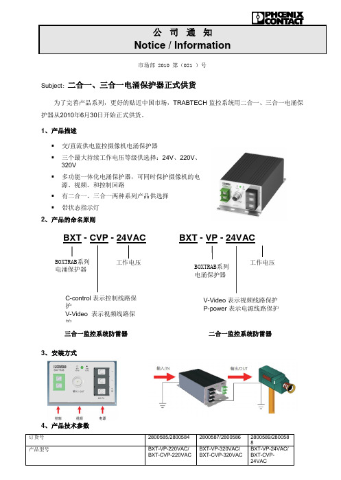
为了完善产品系列,更好的贴近中国市场,TRABTECH 监控系统用二合一、三合一电涌保护器从2010年6月30日开始正式供货。
1、 产品描述
▪ 交/直流供电监控摄像机电涌保护器
▪ 三个最大持续工作电压等级供选择:24V 、220V 、
320V ▪ 多功能一体化电涌保护器,可同时保护摄像机的电
源、视频、和控制回路 ▪ 有二合一、三合一两种系列产品供选择 ▪ 带状态指示灯 2、 产品的命名原则
3、 安装方式
4、 产品技术参数
BXT - CVP - 24VAC BXT - VP - 24VAC
三合一监控系统防雷器
BOXTRAB 系列 电涌保护器
V-Video 表示视频线路保护 P-power 表示电源线路保护
二合一监控系统防雷器
5、 产品尺寸图
如需获得该产品的更多信息请与防雷项目部Ms.胡倩(8367)或Ms.景婷(8307)联系
市场部 2010-07-08。
GC5603规格书

GC5603规格书
GC5603是一款专为小体积移动电源设计的同步整流单芯片解决方案。
内部集成了充电管理单元、放电管理单元、充放电指示单元,还有各种保护单元(包括充电智能温控、过温保护、过充与过放保护、输出过压保护、输出重载保护、输出短路保护等几乎所有安全保护功能以保障芯片及锂离子电池的安全)。
本方案充电电流为 0.7A,放电输出为5V/0.7A,应用电路简单,只需要很少的元件即可实现充电管理和放电管理,具有低成本、率的竞争优势。
特点:
1、独立的充电与放电状态指示
2、内置充电、放电功率 MOS,无需外加
3、输入电压: 4.5V~5.5V
4、预设4.2V/4.35V充电电压
5、支持涓流模式以及零电压充电
6、充电电流: 0.7A
7、输出电流:5V/0.7A
8、BAT放电终止电压:2.9V
9、较大20uA待机电流
10、集成充电管理与放电管理
11、智能温度控制与过温保护
12、集成输出过压保护、短路保护、重载保护
13、集成过充与过放保护
14、封装形式:ESOP8L。
模电 第九章 直流电源

1Байду номын сангаас/21
三、稳压管稳压电路
UI U R UO I R I DZ I L
稳压原理:
()电网电压 UI UO (U Z ) I DZ I R U R UO 1
4. 优缺点
C的耐压值应大于 1.1 2U 2 1.56U 2。
简单易行,UO(AV)高,C足够大时交流分量较小;不适 于大电流负载。
10/21
例 题 : 如 图 所 示 电 路 , 已 知 交 流 电 源 频 率 f=50Hz , RL=200Ω,要求直流输出电压Uo=30V,选择整流二极管 和滤波电容。
五、特点
简单易行,稳压性能好。适用于输出电压固定,输出电流 变化范围较小的场合。
16/21
六、稳压管稳压电路的设计
1. UI的选择:为了具有较好的稳压性能,R应取大些; 但是若R大,则UI也要大,Sr将变大,稳压性能反而变差。 通常, UI=(2~3)UZ 2. 稳压管的选择: UZ=UO I D min I Z 且 I D max I ZM 3. 限流电阻R的选择:保证稳压管既稳压又不损坏。
8/21
滤波电路
一、电容滤波电路
充电
放电速度与正弦 波下降速度相似 按指数规律下降
1. 工作原理
当 u2 uC 时,有一对二极管导通 ,对电容充电, 充电非常小。
当 u2 uC 时,所有二极管均截止 ,电容通过 L放电, 放电 RLC。 R
C 越大, RL越大, τ放电将越大,曲线越平滑,脉动越小。
3. 二极管的选择 二极管承受的最大反向电压 U R max 2U 2 二极管正向平均电流 I D(AV) I L(AV)
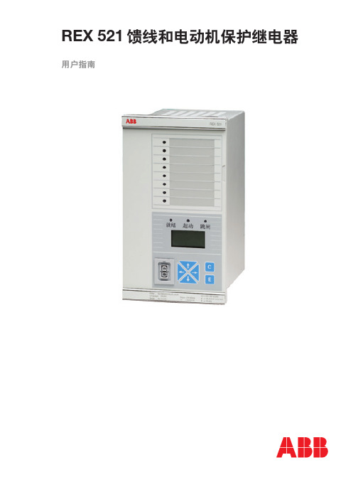
rex521保护使用说明书
3
特性(续)
4
REX 521 馈 线 和 电 动 机 保 护 继 电 器
● 电流测量 ● 零序电流测量 ● 零序电压测量 ● 断路器累积电气磨损计算 ● 故障录波 ● 跳闸回路监视 ● 断路器失灵保护 ● 自动重合闸(1-5 次重合) ● 断路器状态监视及控制 ● 输出自保持 ● 状态监视 ● 就地 / 远方切换选择 ● 用户自定义输入 / 输出 ● 电气联锁 ● 用户自定义告警灯
基本版 B02: ● 三段过流保护 ● 三段零序过流(接地)保护 ● 缺相保护 ● 热过负荷保护 ● 涌流制动 ● 电流输入回路监视 ● 电流波形畸变测量 ● 电流测量 ● 零序电流测量 ● 断路器累积电气磨损计算 ● 故障录波 ● 跳闸回路监视 ● 断路器失灵保护 ● 自动重合闸(1-5 次重合) ● 断路器状态监视及控制
高级版 H06: ● 两段过流保护 ● 两段过电压保护 ● 两段低电压保护 ● 三段零序电压保护 ● 两段频率保护 ● 电流输入回路监视 ● 电压输入回路监视 ● 电流波形畸变测量 ● 电压波形畸变测量 ● 电流测量 ● 零序电流测量 ● 电压测量 ● 零序电压测量 ● 频率测量 ● 三相功率和电能测量 ● 断路器累积电气磨损计算 ● 故障录波 ● 跳闸回路监视 ● 断路器失灵保护
通道。
应用
REX 521 馈 线 和 电 动 机 保 护 继 电 器
REX 521 用途广泛,可用在输、配电网络上作 保护、控制和监视,可用于不同电压等级的中 性点接地、小电阻接地、中性点不接地和谐振 接地的网络。该装置既适用于辐射网也用于环 状网,既适用于单端供电系统也可用于多端供 电的线路。
电源测试之可靠性测试

D、将模块的输入电压调整为过压点-3V,模块的输出为最高输出电压的拐点状态,此时模 块的占空比为最大,连续运行 2 小时,模块不应出现损坏; E、将模块的输入电压调整为效率最低点时的输入电压,模块输出为最高输出电压的拐点状 态,连续运行 2 小时,模块不应损坏。 注意:上述的测试,必须在规格书规定的最高工作温度下进行。 判定标准: 在上述条件下工作,模块没有出现损坏,合格;否则不合格。
8 有源 PFC 性能测试 测试说明: 带有源 PFC 的电源模块,对电网尖锋、毛刺合和谐波比较敏感,应进行全面仔细的测试。 测试方法: 利用 AC SOURCE 交流源作为输入电压源,输出分别带半载、满载,测试输入电流波形和 电压波形,同时监测 PFC 后的电压;测试电网在尖锋、毛刺、谐波情况下输入电压、电流 的相位及幅值关系;测量 PFC 开关管的电流和电压,验证在全电压范围和毛刺、尖锋、谐 波等情况下开关管和其他功率器件的安全性及电流跟踪电压变化的能力。 判定标准: PFC 测试可以作为可靠性参考,出现严重问题时,应及时解决。
(4)电网的半个波头陡升至倍电压,这个波形主要是用来模拟实际电网中会突然出现的谐 振过电压,而且在这种情况下,模块的输入过电压保护线路不起作用,这种冲击对于有 PFC 的电路是存在危险的。测试内容:a、在输入电压为 180V,输出满载的情况下,用 AC SOURCE 模拟该波形,要求 180V 工作 3 分钟,然后电压突然增加到 380V,持续 100ms,然后恢复 到 180V,让模块在这种情况下长时间工作 1 小时,不应损坏;b、设置 AC SOURCE 使得 输入电压为 0V,持续 5 分钟,然后电压突然增加到 380V,持续 100ms,然后恢复到 0V, 让模块在这种情况下长时间工作 1 小时,不应损坏。 具体波形(a 情况下的波形)如下:
SINUMERIK MC Safety Integrated 开机调试手册说明书
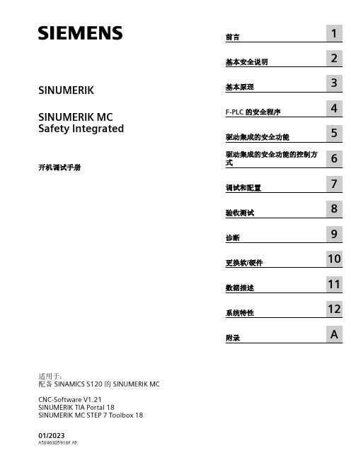
前言
1
基本安全说明
2
基本原理
3
F-PLC 的安全程序
4
驱动集成的安全功能
5
6 驱动集成的安全功能的控制方
式
调试和配置
7
验收测试
8
诊断
9
更换软/硬件
10
数据描述
11
系统特性
12
附录
A
法律资讯 警告提示系统
为了您的人身安全以及避免财产损失,必须注意本手册中的提示。人身安全的提示用一个警告三角表示,仅与财产损 失有关的提示不带警告三角。警告提示根据危险等级由高到低如下表示。
3 基本原理 ........................................................................................................................................ 35
3.1
F-PLC 的安全功能......................................................................................................... 35
1.6
SINUMERIK 操作软件 ................................................................................................... 21
1.7
按照 SINUMERIK 来配置报文 ........................................................................................ 22
威盛智能表说明书

照需量周期进行需量测量,当第一个需量周期完成后,按滑差间隔开始最大需量记录。在一个不完
整的需量周期内,不做最大需量的记录。
(3)功率方向改变时,需量中间单元清零。跨费率时段时,需量中间单元不清零,保证总最大
需量计量的连续性。下面几种情况需量中间单元清零:1电表总清零;2通讯命令清最大需量时;3按键
手动清最大需量时;4功率方向改变时;5跨月结算时。
MODBUS代码 DL/T645代码 数据内容
1.2 产品特点
本仪表采用了高精度采样计量单元和高速 MCU 数据处理单元,可实现高精度宽范围准确计量
和快速数据分析;采用段码式多行宽视角液晶显示屏,显示内容很丰富;液晶配备白色背光,可满
足黑暗环境下查阅数据的要求;采用非易失存储器存储各类数据,可长时间保存数据且掉电不丢失;
采用高精度带温补功能的时钟芯片,在工作温度范围内有效保证了时钟的准确性;支持双通信端口
位号
功能
位值与功能对应关系
缺省值
Bit 7
保留
0
Bit 6
保留
0
Bit 5
需量同步模式
1: 分钟同步 0: 时钟同步
1
Bit 4
极值结算方式
1:按日结; 0:按月结
0
Bit 3
保留
0
Bit 2
保留
0
Bit 1
保留
0
Bit 0
保留Leabharlann 0拟 制:刘展未 尹凌 2013-01-28 审 核: 工 艺: 标准化: 批 准:
GB/T17215.301-2007 多功能电能表 特殊要求
GB/T17215.322-2008 静止式有功电能表(0.2S级和 0.5S级)
c5802开关管参数

c5802开关管参数
C5802开关管是一种常用的电子元件,具有广泛的应用。
它主要用作电流控制开关,能够在高电压和高电流下进行可靠的开关操作。
本文将从不同角度介绍C5802开关管的参数及其特点。
一、导通电阻
C5802开关管的导通电阻是一个重要参数,它代表了在导通状态下的电阻大小。
导通电阻越小,说明C5802开关管在导通时能够提供更大的电流。
这对于一些高电流应用来说非常重要,能够保证电路正常工作。
二、关断电压
C5802开关管的关断电压是指在关断状态下能够承受的最大电压。
关断电压越高,说明C5802开关管能够在更高的电压下正常工作,适用于更高电压的电路应用。
三、开启电压
C5802开关管的开启电压是指在导通状态下需要的最小电压。
开启电压越低,说明C5802开关管能够在较低的电压下实现导通,适用于一些低电压应用。
四、最大电流
C5802开关管的最大电流是指在导通状态下能够承受的最大电流。
最大电流越大,说明C5802开关管能够在更大电流下正常工作,适
用于高电流的应用。
五、功耗
C5802开关管的功耗是指在工作状态下产生的热量。
功耗越低,说明C5802开关管能够更高效地工作,减少能量的损耗。
以上是C5802开关管的一些常见参数及其特点。
通过了解这些参数,我们可以选择合适的C5802开关管来满足我们的需求。
无论是在电源管理、电动工具、或是通信设备等领域,C5802开关管都扮演着重要的角色,为电路的稳定运行提供了保障。
希望通过本文的介绍,读者能对C5802开关管有更深入的了解。
- 1、下载文档前请自行甄别文档内容的完整性,平台不提供额外的编辑、内容补充、找答案等附加服务。
- 2、"仅部分预览"的文档,不可在线预览部分如存在完整性等问题,可反馈申请退款(可完整预览的文档不适用该条件!)。
- 3、如文档侵犯您的权益,请联系客服反馈,我们会尽快为您处理(人工客服工作时间:9:00-18:30)。
_______________________________________________________XySemi Inc - 1 - S5802-SIP of Power Bank Total Solution GENERAL DESCRIPTIONS5802 is one SIP that it integrates Li-Battery Charge management 、Li-BatteryProtection and Boost converter in only TSSOP16-PP package.This SIP can charge with 1A current and also can output 5V 1A to load such as smart phone or MID.It only need few components and can reduce the BOM area and BOM cost.FEATURESz Charger input voltage-4.5V to 6V z Charger current-MAX 1Az Boost converter-MAX 20V output z Boost converter-MAX 5V 1Az Boost converter Frequency-1.2MHz z Li Protection OCU-4.25V ODU-2.9V z Li Protection OCP-3A z Have UVLO 、OTP 、Short protection z TSSOP16-PP PackageAPPLICATIONS• Power bank for MID 、PAD •Power bank for Smart PhoneFigure 1. Typical Application Circuit1____________________________________________________________________________________________________ORDERING INFORMATIONPART NUMBER TEMP RANGE VIN OUTPUT VOLTAGE (V)CHARGE CURRENTPACKAGE PINS S5802-40°C to 85°C4.5~6VADJ1ATSSOP-PP 16PIN CONFIGURATIONFigure 2. PIN ConfigurationPIN DESCRIPTIONPIN NUMBER PIN NAME PIN DESCRIPTION1,2SWBoost Converter’s Switching pin3,12 B+Li-Battery’s Positive Pole ,pin 3 should be bypassed with a 1uF capacitor as close aspossible, Pin12 should be bypassed with a 10uF capacitor as close as possible 4 BSOCBoost Converter’s current limit setting pin ,For 5Vout 1A application ,you can select250K~300Kohm resistor to GND 5 BSEN Boost Converter’s Enable pin 6FBBoost Converter’s Feedback pin. it can set 5Vout with two resistors.7 CHRG Open-Drain Charge Status Output , When the battery is charging, the CHRG pin ispulled low by an internal N-channel MOSFET. When the charge cycle is completed,CHRG pin will be in a high-impedance state. 8 CHEN Charge Enable Pin9PROG Charge Current Program, Charge Current Monitor and Shutdown Pin.10 CHSTD The completion of battery charging instructions side. When the battery charge iscomplete, CHSTD pulled low by internal switches, indicating the completion ofcharging. In addition, CHSTD pin will be in a high-impedance state. 11CHINPositive Input Supply Voltage, should be bypassed with at least a 10uF capacitor.S5802____________________________________________________________________________________________________13 VPBThe Power Supply of Li-Protection section ,Should connect 0.1uF capacitor betweenVpb and B- as close as possible and 100ohm resistor to B+ 14,15 B- Li-Battery’s Negative Pole 16,17GNDGround and EPADABSOLUTE MAXIMUM RATINGS(Note: Do not exceed these limits to prevent damage to the device. Exposure to absolute maximum rating conditions for long periods may affect device reliability.)PARAMETER VALUE UNITSupply Voltage VIN ;CHRG\CHEN\CHSTD Voltage -0.3 to 7 V FB Voltage ;Vpb Voltage ;B+\B-; BSEN pin; BSOC voltage -0.3 to 5 V SW Voltage Vin+0.3 to 15 V PROG Voltage-0.3~CHIN+0.3V Icharge 1.2 APROG Pin current1.2 mA Operating Ambient Temperature -40 to 85 °C Maximum Junction Temperature 150 °C Storage Temperature-55 to 150 °C Lead Temperature (Soldering, 10 sec)260°CELECTRICAL CHARACTERISTICS(V IN = 3.6V, T A = 25°C unless otherwise specified)PARAMETER SYMBOL TEST CONDITIONSMIN TYP MAX UNITInput Voltage Range CHIN 4.5 6.0V Regulated Charge Voltage Vfloat0°C ≤T A ≤85°C, Icharge = 40mA4.158 4.2 4.242V PROG pin Voltage Vprog R PROG =1k, Current mode0.93 1.0 1.07V R PROG =2k,Current mode450 500 550mA R PROG =1k,Current mode900 1000 1100mA Charge current Icharge Standby mode,Vbat=4.2V0 -2.5 -6 uA Trickle charge current Itrikl Vbat<Vtrikl,Rprog=1k 90100110mA Trickle charge Threshold VoltageVtriklR PROG =10K ,Vbat Rising2.8 2.93.0V Trickle voltage hysteresis voltageVtrhys R PROG =10K 6080110mV CHRG pin Output low voltageVchrg Ichrg =5mA 0.35 0.6V CHSTD pin Output low voltageVchstd Ichstd =5mA0.35 0.6VFUNCTIONAL DESCRIPTIONNORMAL OPERATIONS5802 integrates Li-Battery Charger 、Li-Battery Protection and Boost converter in only TSSOP16-PP packageAdapter inputs 5V voltage and charges the battery. After the battery is full, get off the adapter . And then we can boost up to 5V to charge the mobile advices when they is empty.Li-Battery Charger can set charge current by PROG resistor. Normal charging current is set from 0.5A to 1A. It will go into trickle charge mode to protect Li-Battery when BAT voltage is below 2.9V. Li-Battery Protection can detect the battery cell’s status such as Vcu 、Vcl ,Temp 、short-cut 、Over-current and take action to protect battery cell.Boost section can give us 5V 1A capacity to mobile devices.THERMAL OR SHORT-CUT PROTECTIONA thermal shutdown is implemented to prevent damages due to excessive heat and power dissipation. Typically the thermal shutdown threshold is 150℃ .When the thermal shutdown is triggered the device stops switching until the temperature falls below typically 136℃.Then the device starts switching again.If the Boost converter’s Vout is short to GND ,the IC will shut down and you should recharge the battery to get rid of this status.CHEN 、BSEN voltage Ven0.3 1 1.5VRecharge Battery threshold VoltageΔVrecg V FLOAT - V RECHRG 100 200mV Overcharge DetectionVoltage of Li BAT-Protection V CU 4.225 4.25 4.275V Overcharge Release Voltage of Li BAT-Protection V CL 4.075 4.10 4.125V Overdischarge DetectionVoltage of Li BAT-Protection V DL 2.85 2.9 2.95VOverdischarge ReleaseVoltage of Li BAT-Protection V DR2.953.0 3.05VOverdischarge Current1 Detection of Li BAT-ProtectionI IOV1 (V B+)-(V B -)=3.5V 2.1 3 3.9 ALoad Short-Circuiting Detection of Li BAT-ProtectionI SHORT (V B+)-(V B -)=3.5V 10 20 30 ABoost output voltage range Vout 20 VRegulated Feedback Voltage V FB1.118 1.2 1.212VPeak Inductor Current I PEAK Rset=150K Vin=3.3V Vout=5V 0.8 1 1.2 A Peak Inductor Current I PEAK Rset=500K Vin=3.3V Vout=5V2.2 2.55 2.9ABoost ConvertOscillator FrequencyF OSC0.9 1.2 1.5MHzAPPLICATION INFORMATIONINDUCTOR SELECTIONIn normal operation, the inductor maintains continuous current to the output. The inductor current has a ripple that is dependent on the inductance value. The high inductance reduces the ripple current.Selected inductor by actual application:Manufa cturer Part Number Inductance (uH) DRC max(Ohms)Dimensions L*W*H(mm3)2.2 0.0493.3 0.0654.7 0.08 LQH44PN10 0.164*4*1.7 2.2 0.0303.3 0.0444.7 0.058 MurataLQH5BP10 0.1065*5*2 2.2 0017 3.3 0.027 TDK SPM6530T4.7 0.0367.1*6.5*3 744373 240222.2 0.0614.4*4.05WURTH 744777004 4.70.0257.3*7.3*4.5Table 1. Recommend Surface Mount InductorsIf output voltage is 5V ,you can use 2.2uH~ 4.7uH, If output voltage is 12V, 4.7uH~ 10uH is OK , Normal application: Input 3.3V (3.6V or 4.2V) to Output 5V 9V 12V ;Input 5V to Output 9V 12VCAPACITOR SELECTIONThe input capacitor reduces input voltage ripple to the converter, low ESR ceramic capacitor is highly recommended. For power bank application, A 10uF ceramic capacitor is used. The input capacitor should be placed as close as possible to CHIN and GND. Such as Murata GRM21BR60J106 or TDK C3216X5R1A106M A low ESR output capacitor is required in order to maintain low output voltage ripple. one 10~22uF ceramic output capacitor is suitable for most applications. Such as GRM21BR60J226 or TDK C3216X5R1A226M B+-Pin 3 should be bypassed with a 1uF capacitor as close as possible , B+-Pin12 should be bypassed with a 10uF capacitor as close as possible.SET CHARGE CURRENTThe charge current is programmed by connecting a 1% resistor, R PROG , PROG pin to ground. When charging in constant-current mode, this pin servos to 1V. In all modes, the voltage on this pin can be used to measure the charge current using the following formula: I charge = (V PROG /R PROG ) •1000.OUTPUT VOLTAGE PROGRAMMINGThe output voltage is set by a resistive divider according to the following equation:Typically choose R2=30K and determine R1 from the following equation:For example, you can select R2=31.5K R1=100K to set 5VoutDIODE SELECTIONAccording to max Iout and max Vout, you can select suitable diode. Normally we select diode If=(1.5~2)*Ioutmax and VR=(1.5~2)*Voutmax. For high efficiency,suggest that you select low Vf Schottky diode.For example, 5V 1Aout power bank application, you can select MBRA210LT3 or SS24. Using MBRA210LT3, you can get higher efficiency.OC SETTING( SETTING CURRENT LIMIT)S5802 can be adjusted SW current limit by one resistor connected with BSOC pin。
