发散机说明书样本
卡特板彼咯 G3512 稀薄燃气 engines 发电机组燃气发热机说明书

燃气发电机组低热量燃气连续运行770 ekW 962 kVA50 Hz 1500 转/分 400 伏卡特彼勒是领导发电市场的电力解决方案供应商,其动力系统提供无以伦比的可靠性能、耐用、低成本以及高效益。
所示图片可能未反映实际的机器完整的产品附件• 全套的系统扩展附件均由原厂设计和测试• 灵活的选项配置,方便安装和降低成本产品认证系统• 完整的原型机试验• 全球范围的广泛的现场运行证明• 经认证的扭振分析全球范围的产品支持• 卡特彼勒经销商提供了广泛的售后服务支持(包括保养和维修协议)可满足你不同的设备需求• 卡特彼勒® 代理有1600多个分支机构遍布于200个国家。
• 卡特彼勒定期油样分析Cat® S·O·S sm可以极低的成本侦测发动机内部元件的情况,以最大程度提高产品的性能、降低运行成本。
卡特彼勒 G3512 稀薄燃烧 燃气发动机• 精致的高速机设计,延长了发动机的寿命,降低了设备和运行成本• 在低压管道天然气的应用出能达到最佳的性能• 简单的开式燃烧系统提供高的可靠性以及燃料变化的适应性• 领先的高新技术用于点火系统和空燃比控制,降低排放和提高效率• 只需一个电子控制模块就可以实现发动机的所有控制,包括点火、调速、空燃比控制和发动机的保护。
卡特彼勒® SR4B 发电机• 电机的设计符合卡特彼勒燃气发动机的动力输出特性• 行业中领先的机械和电气设计• 更高的效率卡特彼勒燃气发动机仪表板• 简单控制和保护的用户友好界面• 发动机监控特点出厂标配件和选配件系统 标准 可选用的 进气 空气过滤器 空滤更换指示器(散供) 空气进气适配器控制面板 仪表板安装在发动机上冷却 缸套水冷却回路缸套水泵由发动机驱动,温控节温器联合式后冷却和润滑油冷却回路,一级为分道式后冷却器泵由发动机驱动,第二级温控节温器。
耐腐蚀型冷却器 原水冷却器选用热电联供时,可调节冷却温度 进/出水接口连接膨胀溢流水箱液位开关器排气 湿式排气管 弯头,柔性连接,法兰带灭火星的消声器 消声器连接法兰燃料 Deltec天然气混合器发动机后部输入连接燃料热值17.7-23.6MJ/Nm3 (450-600Btu/scf)燃气过滤器 燃气关断阀发电机 SR4B发电机,包括:永磁励磁,绕组模绕结构,H级的绝缘定子温度侦测RTD卡特彼勒CDVR自动电压调节数字模块无功和功率因数KVAR/PF控制防结露线圈空间加热器 整套断路器安装中压发电机轴承温度侦测RTD低压扩展箱母线引入箱发电机用空气过滤器 欧洲标准母线调速 速度控制器Woodward 2301A可满足标准排放 散供 Woodward 2301A2301A负荷分配控制执行器2301D 双增益控制8290负荷分配模块点火 卡特彼勒电子点火系统(E.I.S)爆震正时传感器润滑 曲轴箱呼吸器,顶部安装润滑油冷却器润滑油过滤器浅式油底壳 润滑油油位计 油底壳排放阀 排放泵预润滑泵润滑油安装 330mm结构钢底座 工业级 弹簧式减震块橡胶式减震块保护 24V直流燃气关断电磁阀(通电打开)爆震停机起动/充电 24V起动马达 蓄电池及其电缆和支架电池充电器 充电发电机超大容量电池缸套水加热器其他 卡特彼勒黄色油漆(除水箱和底座)保护曲轴减震器起重吊眼操作和维护手册,零件手册 曲轴箱防爆阀 发动机盘车组件 EEC D.O.I证书技术规格卡特彼勒SR4B发电机机架号 695 励磁 永励磁 节距 0.7333 级数 4 轴承数 1 引线数 6 绝缘 H级 IP等级 防滴漏保护IP22 安装对中 导向轴 超速能力 额定转速的125% 波形偏差(线到线,无负载) 小于3.0% 电压调节器 CDVR 电压调整范围 +/-5.0% 稳态电压调节率 +/-0.5%电压调节率(在3%速度变化内) +/-0.5% 电话影响系数(TIF) 小于50电压种类请咨询当地的卡特彼勒经销商 卡特彼勒燃气发动机仪表板 * 包括:润滑油压力冷却水温润滑油压差进气温度检修时间排气温度计和热电偶进气压力计量卡特彼勒燃气发动机G3512 LE SCAC 4冲程、 火花塞点火燃气发动机缸数 V12缸径mm(in) 170(6.7)冲程mm(in) 190(7.5)排量 L(in) 51.8(3158)压缩比 11:01吸气方式 涡轮增压后冷却回路冷却方式 缸套水,分道式后冷却和润滑油冷却器为一个回路燃料系统 低压执行器类型 Woodward2301A 资料和技术规格可能会有更改,不作另行通知,在本出版物中使用国际单位(SI)技术数据G3512 燃气发电机机组DM 0762排放标准(氮氧化合物NOx) 分道式后冷却 mg/Nm3Deg C50054机组性能 (1)发电机组额定功率@0.8pf(含水泵和不含风扇) 发电机组额定功率@0.8pf(含水泵和不含风扇) 发电机组额定功率@1.0pf(含水泵和不含风扇) 电能效率@1.0pf(ISO 3046/1)(2)机械功率(含水泵和不含风扇) ekW 连续运行kVA 连续运行ekW 连续运行%bkW77096277631.9803燃气消耗量(3)100%负荷(不含风扇) 75%负荷 (不含风扇) 50%负荷 (不含风扇) Nm3/hrNm3/hrNm3/hr391320232海拔高度能力(环境温度25℃时)海拔高度 M500 冷却系统环境温度缸套水出口温度(最高) Deg CDeg C25110排气系统燃烧用空气流量 排气管气体温度 排气流量 Nm3/minDeg CNm3/min50.149154.1机器散热缸套水冷却的散热中冷冷却回路+润滑油冷却回路的散热 废气散热(LHV 至25℃)废气散热(LHV 至120℃)从发动机发散到大气的热量从发电机发散到大气的热量 kWkWkWkWkWkW67024565953710334.6交流发电机 机架温升30%压降时的马达启动能力(4)Deg CskVA6951052521排放(5)氮氧化合物 NOx—含5%的氧(干燥的气体) 一氧化碳 CO—含5%的氧(干燥的气体)总碳氢含 THC—5%的氧(干燥的气体)非甲烷总烃NMHC—含5%的氧(干燥的气体) 废气含氧量(干燥的气体) mg/Nm3mg/Nm3mg/Nm3mg/Nm3%500187014062116.3工况定义与条件(1)连续运行—输出最大功率并且无运行时间的限制功率定义条件:输出功率基于天然气低热值(LHV)为22.4 MJ/Nm3, 和卡特彼勒甲烷数MN为130的稳态工况。
斯普尔兰机械涌散器控制器说明书

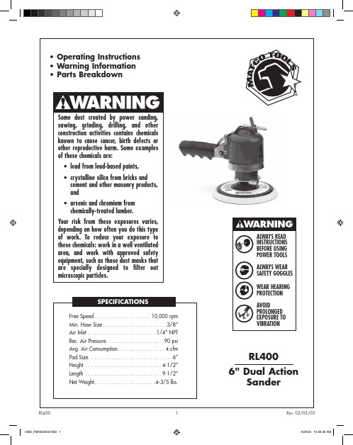
INSTALLATION
When handling the boards, electrostatic protection procedures should be followed. The person installing the controller should be grounded through a ground strap. If ground straps and other ESD protection are not available, handle the board only by the edges of the board. Another fairly safe place to hold the board is by the battery holders. DO NOT TOUCH ANY COMPONENTS ON THE BOARD EXCEPT THE BATTERY HOLDER OR RELAYS.
ized. The sensor should be mounted to the suction line after the evaporator using the furnished clamps. 5. Connect leaving liquid temperature sensor to TS1. The sensor is not polarized. 6. The pressure transducer should be mounted on the suction line near the temperature sensor location. Sporlan has supplied transducer cables with two combinations of wire colors. Connect the wires to the terminals on the board in accordance with Table 1 below. If the cable is spliced in the field to extend its length, care must be taken to assure that the new wire is properly connected to the board. 7. DI1 is a digital input used to close the valve. A short or closed contact from an external relay will close the valve for pump down.
DUSTTRAK8520型智能粉尘检测仪使用说明书

DUSTTRAK 8520型智能粉尘检测仪使用说明书上海汇分电子科技有限公司电话:手机:Email:Http:目录安全信息------------------------------------------------1 装箱单------------------------------------------------取出仪器DUSTTRAK -------------------------------------- 仪器面板及包装箱内部件说明---------------------------- 2 设置--------------------------------------------------为DUSTTRUK的供电-------------------------------------- 电池安装----------------------------------------------使用AC适配器------------------------------------------ 仪器设置----------------------------------------------安装T RAK P RO数据分析软件------------------------------- 连接仪器到计算机-------------------------------------- 设置计算机通信端口------------------------------------ 设置真实时间------------------------------------------用T RAK P RO软件调整时间/日期---------------------------- 手动调整时间/日期------------------------------------- 连接8928便携式打印机---------------------------------- 连接模拟信号/警报器----------------------------------- 3 3 3 4 6 6 6 6 6 6 6 7 8 8 8 8 93 操作--------------------------------------------------浏览--------------------------------------------------仪器键盘功能------------------------------------------ON/OFF键---------------------------------------------- SAMPLE键---------------------------------------------- TIME CONSTANT键--------------------------------------- 设置时间常数------------------------------------------ STATISTICS 键----------------------------------------- PRINT 键---------------------------------------------- SAMPLING MODE 键-------------------------------------- 测量模式----------------------------------------------记录模式---------------------------------------------- CLEAR MEMORY 键--------------------------------------- LOGGING INTERVAL 键----------------------------------- 使用TRAKPRO 数据分析软件设置采样间隔------------------ 键--------------------------------------------- CALIBRATE 键------------------------------------------显示/控制面板锁定开关---------------------------------遥控采样----------------------------------------------使用气旋式采样器采样----------------------------------使用气旋式采样器--------------------------------------使用1.0或2.5µm 喷嘴-----------------------------------使用10µm喷嘴------------------------------------------模拟输出----------------------------------------------警报输出----------------------------------------------警报输出说明------------------------------------------设置报警点-------------------------------------------- 9 9 9 9 1010111112 12 121213 131314 141415 1515161717181819升级仪器添加模拟输出和警报输出功能-------------------- 识别仪器模拟输出/警报输出功能------------------------- 识别仪器能否升级添加模拟输出/警报输出功能------------- 识别仪器能否升级--------------------------------------设置高级模式:LOG2和LOG3 ------------------------------ LOG2和LOG3模式的采样协议------------------------------ 进行预设定采样时应注意事项---------------------------- 记忆卡注意事项----------------------------------------自定义校准--------------------------------------------确定某一粉尘的特定因子-------------------------------- 从控制面板设定校正因子-------------------------------- 通过TrakPro数据分析软件设定校正因子------------------- 将存储数据转化为校正数据------------------------------ 4 保养与维护--------------------------------------------维护时间表--------------------------------------------归零检测/重新归零-------------------------------------清洗1.0µm和2.5µm喷嘴--------------------------------- 清洗10µm喷嘴和采样管---------------------------------- 更换内置过滤器----------------------------------------调整流量----------------------------------------------清洗气旋式取样器--------------------------------------仪器储存提示------------------------------------------5 疑难解答----------------------------------------------附录A ------------------------------------------------- 19192020212324 2424252626272829293031323333343536安全信息使用时请按照我们提供的使用说明,这个仪器是依据1968年的健康和安全法案通过美国健康和为人服务的标准设计的一款激光原理的仪器。
盐匀撒器产品说明书

Installation InstructionsTGS03 Salt Spreader TGS03RED Salt Spreader TGS03YEL Salt SpreaderUS PATENT 8,888,025; 9,562,333other PATENTS PENDINGWARNINGObserve the following Safety Precautions before,during and after operating this spreader. By following these precautions and common sense, possible injuryto persons and potential damage to this machine may beavoided.Safety Precautions1. Read this entire Installation Instruction before oper-ating this spreader.2. Read all safety decals on the spreader before operating.3. Verify that all personnel are clear of thespreader spray area before starting or operating this spreader.4. Do not adjust, clean, lubricate or unclog material jams without first turning off the spreader.5. Make sure the spreader is securely fastened to the vehicle in accordance with this manual.6. Do not operate a spreader that is in need of mainte-nance or repairs.7. Always disconnect the battery before removing or replacing electrical components.Spreader AssemblyCheck contents of box against parts list to make sure all components are included. When ordering replace-ment or spare parts refer to parts list for part numbers.1. Slide frame #3019400 into hitch receiver. Fig. 1.2. Slide hopper assembly #3019372 between frameuprights with front portion rested on the truck’s bumper.Fig. 2.Fig. 2SPREADER CANNOT BE SUPPORTED BY FRAME ONLY! SPREADER HOPPER MUST REST ON BUMPER OR SIMILAR STRUCTURE ATTACHED TO TRUCK FRAME.7. Attach shield #3015707 to trough bracket as shownin Fig.78. Attach spinner protector #3018923 to spreader frame asshown in Fig.8.Fig. 7Fig. 10Fig. 1110. Attach bracket and handle of draw latch to lid #3019410using 2 10-24 screws as shown in Fig.10. Attach draw latchcatcher to the hopper as shown in Fig.11.CLEVIS PIN1420014COTTER PIN FPC007800075LTCH WJ215SCREW 10-24 X .75LID 3019410Installing Controller and Wiring• Route both wire harnesses into truck cab through firewall (it maybe necessary to drill holes). Insulate hole to avoid water leaks.• Insure no wires are nicked or damaged during installation.• Connect the 4-pin connecter on the wire harness to the control box.• Connect the 2-pin connector on the power cable to the control box.• Lay out a path for the power cable to the battery, use quick ties to secure power cable. DO NOT CONNECT TO BATTERY AT THIS TIME!• Lay out path for wire harness to the rear of the vehicle. It is recommended to stay clear of the exhaust system. Excess heat can damage the wire harnesses. Use quick ties to secure harness to underbody.• Connect the wire harness to the motor and vibrator.• Connect the power and ground cables directly to the battery.• Insure all functions of the controller are working properly.• Note: direction of spinner may be changed by interchang-ing the motor leads.THIS IS WIRE GROUND ELECTRICAL SYSTEM! NO CONNECTIONS TO TRUCK’S FRAME OR BODY ALLOWED!NOTE: Always disconnect battery before attempting to install electrical components on your vehicle. Mount the controller in a convenient locationin the truck cab. It is recommended not to mount the controller directly in front of heat vents. Allow ampleair space around controller.CAUTIONDO NOT MOUNT CONTROLLER IN THE WAY OF AIR BAG DEPLOYMENT!301186430086203035934CB50PB3001379BATTERY POSITIVEBATTERY NEGATIVESpreader Operation.1. Due to the rate at which materials absorb moisture dif-ferently, some materials may not perform as desired.Therefore, the substitution of an alternative material may be necessary for optimum performance.2. When filling hopper use only screened material. Preventlarge chunks of material and debris from getting intohopper and cause operational problem or damage.3. Material must never be left in the hopper for extendedperiod of time. Material will absorb moisture, bind, hard-en and may prevent spreader from proper operation or may damage the spreader.4. To start spreader make sure that truck engine is running.Flip POWER switch in ON position. Switch will illuminate.Spreader motor will accelerate to full speed and then it will slow down to previously dialed speed.5. To adjust material flow rate and spreading distance, sim-ply rotate speed knob to desired speed. Spreader can be put in full speed mode for short time by pressing and holding BLAST button.6. To activate and deactivate vibrator (optional) pressVIBRATOR button, if equipped.7. Material flow and pattern can be adjusted by opening/close adjustable discharge on the trough bottom.Be careful adjusting discharge opening. Closing thisopening too much will created back pressure and stall gear motor.Optional vibrator installation.To install optional vibrator, order kit #3020340. Drill 3/8 clearance holes thru hopper using bind holes as guides. Place plate inside hopper; align holes in plate with holes in hopper. Place vibrator on outer hopper wall and secure itto hopper using 4 carriage bolts 3/8-16 x 3.25 and 4 nylock nuts 3/8-16. Connect vibrator cable to mating connector on wire harness 3008620.Check fasteners every 5-7 hours of operation. Retighten if necessary.Controller Warnings.Check controller instruction sheet for latest controller updates, troubleshooting codes. Controller instruction sheet is inside controller shipping box.IMPORTANT! INSTALLER, DO NOT DISCARD CONTROLLER INSTRUCTION SHEET. STAPLE SHEET TO SPREADER MANUAL AND GIVE TO END USER! Maintenance Instructions.1. Wash spreader after every use. Make sure no materialleft under auger and/or inside trough.2. Inspect and retighten fasteners after every 5-7 hours ofoperation.3. Lubricate bearing every 7-10 hours of operation usinggeneral automotive grease.4. Inspect terminals/ connectors every time you disconnectspreader from wire harness. Apply thin layer of dielectric grease on terminals. If any tarnish/corrosion found, clean terminals and apply dielectric grease.End of Season Maintenance.1. Wash spreader. Make sure no material or residue left inand outside hopper.2. Lubricate bearing using general automotive grease.3. Inspect wire harness, connectors for broken insulation,missing components. Replace if necessary.4. Apply dielectric grease on all electrical connectors.5. Store hopper indoors, in dry, cool place.6. Inspect, clean and repaint frame.7. Remove controller from truck. Store controller indoors, indry, cool place.Bill of MaterialsITEMPART NO.QTY. DESCRIPTION13015383 1TROUGH ASSEMBLY TGS072 3019471 1HOPPER POLY30265541HOPPER POLY , RED 30265561HOPPER POLY , YELLOW 3 FWF031075006SS6WASHER, 5/16 SAE SST430067216SCREW, HEX HD, 5/16-18 X 3/4 GR5 SS5 3015694 1MOTOR COVER TGS076 30159254SCREW #14X1.25 SST730179841CAP ROUND 1.312 ID VINYL BLACKITEMPART NO.QTY.DESCRIPTION130153771 GEAR MOTOR DUAL SHAFT .5 HP 12 VDC23015381 1 TROUGH WELDMENT, TGS073 3015382 1 AUGER TGS074 14110001 BEARING, 2-HOLE FLANGED 1"5 FWF031075006SS 4 WASHER, 5/16 SAE SST6 3006721 4 SCREW, HEX HD, 5/16-18 X 3/4 GR5 SS7FPY0310001501PIN, CLEVIS, 5/16 X 1-1/2, W/ 5/32 PH, ZN8 3014994 1 PIN,COTTER,1/8IN X 1IN SST 9FNE038016044SS 4 NUT, NYLOCK 3/8-16 X 7/16 SST10 3019374 1 DISCHARGE, ADJUSTABLE 11 30121441 BOLT, RHSQN,.25-20X.5 SST 12 FWF038100007SS 2 WASHER, FLAT 3/8 USS SST 13 FCS038016075SS 2 SCREW, HHC-3/8-16 X 3/4 SST 14 FWF025063007SS 1 WASHER, FLAT 1/4 SAE SS 1530167511NUT,WING 1/4-20 SSTBill of MaterialsTGS03 Trough AssemblyTGS03 Hardware BagITEMPART NO.QTY.DESCRIPTION1 3011864 1 CONTROLLER TGS W/ VIBRATOR SWITCH2 3035934 1 WIRE HARNESS, POWER TGS3 3008620 1 WIRE HARNESS MAIN W/ VIBRATOR, TGS4 3017039 2 SCREW, HEX HEAD CAP 1/2-13 X 6.00 SST FULL THREAD5 3001523 4 NUT, HX FLNG-1/2-13 SST6 3000269 10 WASHER, FLAT 1/2 USS, SST7 30012504 SCREW, HHC-1/2-13 X 3 SST 8 FNE050013053SS 6 NUT, NYLOCK 1/2-13 SS 9 14200141 PIN CLEVIS, 1/4 X 2.510 FPC007800075 1 COTTER PIN, 5/64 X 3/4ITEMPART NO.QTY.DESCRIPTION12 30013791 BATTERY CABLE13 FCS038016100SS 2 SCREW, HHC 3/8-16 X 1 304 SST 14 WJ2152 LATCH DRAW RUBBER15 FBSH01002475SS 6 SCREW, BHC #10-24 X .75 SST 16 1420016 1 PIN, HAIR COTTER, CLEAR ZINC 17 30178584 WASHER FLAT .5 ID 1.5 OD SST 18 FWF038100007SS 4 WASHER, FLAT 3/8 USS SST 19 FNE038016044SS 2 NUT, NYLOCK 3/8-16 X 7/16 SST 20 FCS038016200 4 SCREW, HHC 3/8-16 X 2 GR 5 ZP 21 FWF038100007 4 WASHER, FLAT 3/8 USS ZINC 22 FNE038016044 4 NUT, NYLOCK 3/8-16 X 7/16 ZINC3018421 1 ANTI SEIZE LUBRICANT POUCH 5 GRAM CB50PB 1CIRCUIT BREAKERBill of Materials。
Antari FT-200火雾机器手册说明书

FT-200 Fire TrainingFog Machine User ManualIP33ENGLISH©2017 Antari Lighting and Effects Ltd.User Manual - EnglishSafety InformationPlease read the following safety information carefully before operating themachine. This information includes important safeguards about installation,usage, and maintenance. Pay attention to all warning labels and instructions inthis manual and printed on the machine.If you have questions about how to operate the machine safely, please contact your local Antari dealer for help.․Keep this device dry.․Always connect to a grounded circuit to avoid risk of electrocution.․Before connecting machine to power, always check voltage indicate on machine match to your local AC voltage. Do not use the machine if AC power voltage does not match. ․Disconnect the machine from AC power before servicing and when not in use.․This product is for indoor use only! Do not expose to rain or moisture. If fluid is spilled, disconnect AC power and clean with a damp cloth. If fluid is spilled onto electronic parts, immediately unplug the machine and contact your local Antari dealer for advice.․No user serviceable and modifiable parts inside. Never try to repair this product, an unauthorized technician may cause damage or malfunction to the machine.․For adult use only. Never leave the machine running unattended.․Installed the machine in a well-ventilated area. Provide at least 50 cm space around the machine.․Never add flammable liquid of any kind to the machine.․Make sure there are no flammable materials close to the machine while operating.․Only use Antari fluid. Other fluid may lead to heater clog and malfunction.․If the machine fails to work, unplug the machine and stop operation immediately.Contact your local Antari dealer for advise.․Before transporting the machine, make sure the fluid tank is completely drained.․Fog fluid may present health risks if swallowed. Do not drink fog fluid. Store it securely.In case of eye contact or if fluid is swallowed, immediately look for medical advice.․If the supply cord is damaged, it must be replaced by a special cord or assembly available from the manufacturer or its service agent.․The appliance is not to be used by persons (including children) with reduced physical, sensory or mental capabilities, or lack of experience and knowledge․Children being supervised not to play with the applianceUnpacking and InspectionImmediately upon receiving the machine, carefully unpack the carton, check the content to ensure that all parts are present and have been received in good condition. If any parts appear damaged or mishandled from shipping, notify the shipper immediately and retrain the packing material for inspection.What is included: 1 x FT-200 Fog Machine1 x W-2 Wireless Remote1 x Power Cord1 x User ManualProduct Dimensions301 mm 414 mm194 mmProduct OverviewSetting UpIP33 RATING ONLY WHEN OPERATED UPRIGHT / VERTICAL POSITION.Step 1: Place the machine on a flat surface and in a suitable large area with at least 50 cm open space around the machine.Step 2: Fill the fluid tank with Antari approved fluid.Wireless Receiver XLR 5-Pin DMX Connector PowerCON TRUE1 Waterproof Connector Wire Remote SocketTimer / Volume Control Knobs BreakerStep 3: Connect the machine to suitable rated power supply.To determine the power requirement for the machine refer to the label on the back of the machine.Always connect the machine to a protected circuit and ensure it is properlygrounded to avoid risk of electrocution.Step 4: Turn on the machine and allow it to heat up. Heat up takes approximatly 7.5 mintues. Once the machine has reached operating temperature, the LCD display will show “Ready To Fog”. Now the machine is ready for operation.Step 5: To start making fog, locate the rotary knob on the right side of control panel, and press the rotary knob to start making fog.Step 6: To turn off the machine, press rotary knob button again and turn Powercon to the OFF position.OperationControl Panel OperationThe machine can be operated with the onboard digital control interface.Operation - Timer ModeOperation – Volume ModeSettingControl MenuSet interval time from 5 to 200 secondsSet duration time from 1 to 200 secondsSet output volume from 1 to 100%Interval SetXXX SDuration SetXXX STimer OutputXXX %Set output volume from 1 to 100%Set DMX address from 1 to 512Turn ON or OFF wireless remote featureTurn ON or OF F memory setting. When turned “ON”, the machine will return to its original state before last shut off.Turn ON or OFF rotary knob soundPair or unpair wireless remoteTurn ON or OFF nonstop burst function. Once the machine is turned on, it can produce output continously without reheating.Wireless OperationWireless remote control system W-2 consists of a transmitter equipped with four buttons to activate, deactivate, increase and decrease fog output and an onboard receiver attached to the rear panel of FT-200 fog machine.W-2 Wireless TransmitterVolume OutputXXX %DMX512Address:XXXWirelessONRun Last SettingOFFKeypad SoundONWireless DetectPairNonstop BurstOFFPress [A] button to emit fog. Press [B] button to stop. Press [C] button to increase output volume. Press [D] button to decrease output volume.In a free open space the effective distance is 50 meters, actual usage depending on obstacle level the effective distance is 10-25 meters.Wireless ReceiverRegistering a transmitterTransmitters can be paired or deleted from the receiver. Each receiver can pair up to 5 transmitters. Follow the steps below to pair or delete a transmitter from a receiver.Step 1: Press and hold the left rotary knob for 3 seconds to enter setting menu.Step 2: Rotate the rotary knob to find the “Wireless Detect” menu.Step 3: Follow the menu instruction to pair or delete a transmitter.Transmitter battery replacementIf the effective distance seems to decrease, it is possible the battery level is low and requires replacement. In order to replace the battery, undo the three screws on the back of transmitter to release the cover. Replace with same type and specification of battery which is 27A 12VDMX Connector Pin AssignmentThe machine provides 5-pin XLR connectors for DMX connection. The diagram below indicates pin assignment information.DMX Channel FunctionOnly use Antari FLP water-based liquid for the FT-200 Fire Training Fog Machine. The machine is tested and calibrated with this liquid to get the best output performance. Warranty will be void if any other type of liquid is used, improper use of liquid may lead to machine failure and malfunction.․ Do not allow the machine to become contaminated.․ Remove dust from air vents with air compressor, vacuum or a soft brush. ․ Only use a damp cloth to clean the casing.․Before storing run distilled water through the system to help avoid condensing the pump or heater.․It is recommended to run the machine on a monthly basis in order to achieve best performance and output condition.․Excessive dust, liquid and dirt built up will degrade performance and cause overheating.Breaker ResetDisconnect AC power before resetting the breaker. Only replace fuse with sametype and rating.Step 1: Disconnect AC power.Step 2: Flip breaker to ON position.Step 3: Turn on machine for testing.Breaker120V = 13.5A 250V230V = 7A 250VTechnical SpecificationsInput voltage US 120V EU 230VUK 240V JP 100VBreaker 120V = 13.5A 250V230V = 7A 250VHeater 1600WWarm-up time 7.5 min. (approx.)Max. operating time 8 min. at 100% outputFluid tank capacity 2.4 LFluid consumption 270 ml/minCompatible fluid Antari FLP water-based fluidControl option DMX 512, Manual, Timer, W-2 Wireless remote ,Z-3 Remote (optional)DMX channels 1 channelPower connection Neutrik PowerCON TRUE1DMX data connection 5-pin XLRDimension L 301 x W 194 x H 414 mmDry weight 16 kgIP Rating IP33 RatingC08FT2001。
Evolution Wireless Digital EW-DX SKM-S 手持传输器说明书

Handheld TransmitterLA ENTREGA INCLUYE• EW-DX SKM transmisor de mano • MZQ 1 abrazadera de micrófono • 2 baterías AA • Guía rápida• Manual de seguridad • Declaración del FabricanteTransmisor de mano robusto y versátil con o sin interrup-tor.CARACTERÍSTICAS• Potencia de RF de 10 mW con un alcance de trabajo dehasta 100 m/328 ft • Contactos de carga para carga en el dispositivo conCHG 70N • Pantalla eInk Display persistente: parámetros visiblesen la pantalla, incluso cuando el dispositivo no está encendido • Interruptor de silencio programable en EW-DX SKM-S:personaliza el dispositivo en función de sus necesida-des profesionales • Botones de función: controlan todos los ajustes deltransmisor directamente desde el micrófono de mano • Mayor tiempo de funcionamiento con baterías de ionesde litio: hasta 12 horas de funcionamiento • Interfaz de cápsula estándar: compatible con unaamplia gama de cápsulas Sennheiser y Neumann • Función de control del trim de la entrada del micrófono •Carcasa metálicaHandheld Transmitter ESPECIFICACIONESSistemaRangos de frecuencia de conexión de audio Q1-9R1-9S1-10S2-10S4-10U1/5V3-4V5-7Y1-3470.2 - 550 MHz520 - 607.8 MHz606.2 - 693.8 MHz614.2 - 693.8 MHz630 - 693.8 MHz823.2 - 831.8 MHz &863.2 - 864.8 MHz925.2 - 937.3 MHz941.7 - 951.8 MHz &953.05 - 956.05 MHz &956.65 - 959.65 MHz1785.2 - 1799.8 MHzRango de frecuencia(BLE) Bluetooth® LowEnergy2402 - 2480 MHzRespuesta de frecuen-cia de audio20 Hz - 20 kHz (-3 dB)Distorsión armónica total ≤ -60 dB for 1 kHz@ -3 dBfs nivel de entradaRango dinámico134 dB Latencia del sistema 1.9 msTemperatura de operación -10 °C - +55 °C (14 °F - 131 °F)Humedad relativa 5 - 95 % (sin condensación)EW-DX SKM (Transmisor de mano)Voltaje de entrada 2.0 - 4.35 VCorriente de entrada< 300 mAFuente de alimentació 2 baterías AA de 1.5 V(alkali manganese)(manganeso alcalino) obatería recargable BA 70 Ancho de banda ocupado200 kHzPotencia de transmisión(radiada)Conexión de audio: 10 mWERP(Range Y1-3: 12 mW ERP)Modo LD: 10 mW ERPBLE: max. 10 mW EIRP Dimensiones (ø x l)(incl. Módulo de micrófonoMMD 835)(sin el módulo demicrófono)50 x 268 mm40 x 200 mmPeso (sin baterías)(incl. Módulo de micrófonoMMD 835)(sin el módulo demicrófono)aprox. 304 gaprox. 195 gVARIANTES DE PRODUCTOEW-DX SKM-S (Q1-9)470.2 - 550 MHz Art. no. 509412 EW-DX SKM-S (R1-9)520 - 607.8 MHz Art. no. 509413 EW-DX SKM-S (S1-10)606.2 - 693.8 MHz Art. no. 509414 EW-DX SKM-S (S2-10)614.2 - 693.8 MHz Art. no. 509417 EW-DX SKM-S (S4-10)630 - 693.8 MHz Art. no. 509418 EW-DX SKM-S (U1/5)823.2 - 831.8 MHz & 863.2 - 864.8 MHz Art. no. 509419 EW-DX SKM-S (V3-4)925.2 - 937.3 MHz Art. no. 509421 EW-DX SKM-S (V5-7)941.7 - 951.8 MHz & 953.05 - 956.05 MHz & 956.65 - 959.65 MHz Art. no. 509422 EW-DX SKM-S (Y1-3)1785.2 - 1799.8 MHz Art. no. 509423 EW-DX SKM (Q1-9)470.2 - 550 MHz Art. no. 509426 EW-DX SKM (R1-9)520 - 607.8 MHz Art. no. 509427 EW-DX SKM (S1-10)606.2 - 693.8 MHz Art. no. 509428 EW-DX SKM (S2-10)614.2 - 693.8 MHz Art. no. 509431 EW-DX SKM (S4-10)630 - 693.8 MHz Art. no. 509432 EW-DX SKM (U1/5)823.2 - 831.8 MHz & 863.2 - 864.8 MHz Art. no. 509433 EW-DX SKM (V3-4)925.2 - 937.3 MHz Art. no. 509435 EW-DX SKM (V5-7)941.7 - 951.8 MHz & 953.05 - 956.05 MHz & 956.65 - 959.65 MHz Art. no. 509436 EW-DX SKM (Y1-3)1785.2 - 1799.8 MHz Art. no. 509439Handheld TransmitterCOMPATIBILIDAD DEL MICRÓFONOMódulos de micrófono compatibles con el transmisor de mano EW-DX SKM-SMMD 835-1Módulo de micrófono dinámico con patrón polar cardioideMMD 845-1Módulo de micrófono dinámico con patrón polar supercardioideMME 865-1Módulo de micrófono condensador pre-polarizado con patrón supercardioideMMD 935-1Módulo de micrófono dinámico con patrón polar cardioideMMD 945-1Módulo de micrófono dinámico con patrón polar supercardioideMMK 965-1Módulo de mic condensador con cardioide conmutable y patrón polar supercardioide MMD 42-1Módulo de micrófono dinámico con patrón polar omnidireccionalNeumann KK 204Módulo de micrófono condensador con patrón polar cardioideNeumann KK 205Módulo de micrófono condensador con patrón polar supercardioideMM 435Módulo de micrófono dinámico con patrón polar cardioideMM 445Módulo de micrófono dinámico con patrón polar supercardioideME 9002Módulo de micrófono condensador pre-polarizado con patrón polar omnidireccionalME 9004Módulo de micrófono condensador pre-polarizado con patrón polar cardioideME 9005Módulo de micrófono condensador pre-polarizado con patrón polar supercardioideACCESORIOSBA 70Batería recargable para SK y SKM-S Art. no. 508860 L 70 USB Cargador para batería recargable BA 70Art. no. 508861 EW-D CHARGING SET Set de cargador L 70 USB y 2 baterías recargables BA 70Art. no. 508862 CHG 70N Cargador de red para SK, SKM y BA 70Art. no. 509455 CHG 70N + PSU KIT Cargador de red para SK, SKM y BA 70Art. no. 509456Handheld TransmitterSennheiser electronic GmbH & Co. KG · Am Labor 1 · 30900 Wedemark · Germany · DIMENSIONES40.31.59Mikrofonmodul MMD835 - nur Beispiel microphon module MMD835 - example only341.34268.510.5750.51.99200.77.9156.56.16。
DET-TRONIC 95-C533 火灾和气体探测 释放系统 说明书

说明95-C533 Eagle Quantum Premier®火灾和气体探测/释放系统第 1 部分 – 安全提醒消息 ................................................................................1-1第 2 部分 – 简介系统说明 ...............................................................................2-1通信回路........................................................................2-1 LON 通信心跳 ...............................................................2-2操作原理........................................................................2-2控制器日志....................................................................2-4控制器用户逻辑.............................................................2-4通信网络故障操作 .........................................................2-4多个接线故障 ................................................................2-5主要组件说明........................................................................2-5系统控制器....................................................................2-5局部操作网络 (LON) ......................................................2-6网络延伸器.............................................................2-6 EQ21xxPS 系列电源和EQ2100PSM 电源监视器......................................2-7 EQP21XXPS(–X) 电源和EQP2410PS(–P) 转换器.......................................2-7 EQ2220GFM 接地故障监视器.......................................2-7现场设备........................................................................2-7火焰探测器.............................................................2-7EQ3730EDIO 增强型离散 I/O 模块........................2-8EQ3700 8 通道 DCIO 模块....................................2-8EQ3720 8 通道继电器模块 ....................................2-9EQ3710AIM 模拟输入模块.....................................2-9EQ3740IPM 智能保护模块...................................2-10EQ3750ASH 可寻址烟热模块................................2-10EQ25xxARM 灭火剂释放模块...............................2-11EQ25xxSAM 信号声频模块 .................................2-12EQ22xxIDC 系列启动设备电路............................2-12EQ22xxDCU/EQ22xxDCUEX 数字通信装置.......................................................2-13 PIRECL PointWatch Eclipse ................................2-13OPECL Open Path Eclipse ..................................2-13UD10 DCU 模拟器...............................................2-13第 3 部分 – 安装安全系统设计要求.................................................................3-1确定保护区域 ................................................................3-1确定接线、网络 (LON) 和系统电源要求........................3-1综合接线要求.........................................................3-1电源接线 ................................................................3-1系统接线(ATEX 和 IECEx) ................................3-1确定电源要求.........................................................3-3EQ211xPS、EQ213xPS 和 EQ217xPS 电源 ........3-5备用电池 ................................................................3-5电池充电器.............................................................3-5EQP21x0PS(–X) 电源 ...........................................3-6EQP2410PS(–P) 转换器........................................3-6确定电源要求.........................................................3-7屏蔽线接地.............................................................3-8接线盒接地.............................................................3-8响应时间与系统尺寸 .............................................3-8水气损坏保护.........................................................3-8静电放电 ................................................................3-8接地故障监视器 (GFM) 安装.................................................3-8安装.......................................................................3-8接线.......................................................................3-8网络和网络延伸器安装..........................................................3-9安装.......................................................................3-9接线.......................................................................3-9启动设备电路 (IDC) 安装 .....................................................3-11 EQ22xxIDC 系列启动设备电路 ....................................3-11安装......................................................................3-11接线......................................................................3-11 EQ22xxIDCGF 系列启动设备电路接地故障................3-12安装.....................................................................3-12接线.....................................................................3-12 EQ22xxIDCSC 系列启动设备电路短路.......................3-13安装.....................................................................3-13接线.....................................................................3-13目录EQ3XXX 控制器安装 ..........................................................3-14外壳要求......................................................................3-14安装.............................................................................3-14串行接口板..................................................................3-14接线.............................................................................3-15电源接线 ..............................................................3-15电气连接 ..............................................................3-15控制器至控制器通信....................................................3-19配置.............................................................................3-22软件定义的地址 ...................................................3-22 EQ3XXX 冗余控制器安装...................................................3-22外壳要求......................................................................3-22安装.............................................................................3-22接线.............................................................................3-22 LON 接线.....................................................................3-22高速串行链路 (HSSL) ..................................................3-22配置.............................................................................3-23 S3 配置................................................................3-23控制器地址...........................................................3-23MODBUS .............................................................3-23CONTROLNET ....................................................3-23 EQ21XXPS 系列电源和电源监视器安装 ..................................................................3-23安装.............................................................................3-23接线.............................................................................3-23启动.............................................................................3-25测量电池电压和充电电流 ............................................3-26 EQP2XX0PS(–X) 电源和冗余模块安装......................................................................3-26安装.............................................................................3-26接线.............................................................................3-26启动.............................................................................3-29 EDIO 模块安装 ...................................................................3-29配置.............................................................................3-33 8 通道 DCIO 安装 ...............................................................3-34安装.............................................................................3-34接线.............................................................................3-34配置.............................................................................3-38 8 通道继电器模块安装 ........................................................3-38安装.............................................................................3-38接线.............................................................................3-38配置.............................................................................3-39模拟输入模块安装...............................................................3-40安装.............................................................................3-40接线.............................................................................3-40配置.............................................................................3-41智能保护模块安装...............................................................3-42接线.............................................................................3-42配置.............................................................................3-45气体探测器位置和安装........................................................3-46影响气体探测器性能的环境和物质..............................3-46适用于 DET-TRONICS H2S/O2 传感器或其它双线4-20 毫安设备的 EQ22XXDCU 数字通信装置.....3-47装配和接线流程 ...................................................3-47带 H2S 和 O2 传感器的 DCU 的传感器分离........3-48用于 PointWatch/DuctWatch 的 EQ22xxDCU数字通信装置.......................................................3-49装配和接线流程 ...................................................3-49带 POINTWATCH 的 DCU 的传感器分离 ............3-49 EQ22xxDCUEX 数字通信装置(用于 Det-Tronics 可燃气体传感器) ..............................................................3-50安装.....................................................................3-50接线.....................................................................3-50带 DCUEX 的传感器分离.....................................3-51 EQ25xxARM 系列灭火剂释放模块..............................3-53安装.....................................................................3-53接线.....................................................................3-53水淋和预作用的监控的输出 .................................3-55跳线.....................................................................3-55地址设置 ..............................................................3-55 EQ25xxSAM 系列信号声频模块.................................3-55安装.....................................................................3-55接线.....................................................................3-55跳线.....................................................................3-56地址设置 ..............................................................3-56系统配置 .............................................................................3-57设置设备网络地址 .......................................................3-57网路地址概述.......................................................3-57设置现场设备的地址 ............................................3-57典型应用 .............................................................................3-57第 4 部分 – 操作系统控制器............................................................................4-1按键...............................................................................4-1控制器状态指示灯 .........................................................4-2文本显示屏....................................................................4-2控制器菜单选项.............................................................4-2控制器声频警报.............................................................4-6 ControlNet 状态指示灯(可选)....................................4-7配置数据下载期间的事件序列 .......................................4-7控制器冗余....................................................................4-9增强型离散 I/O 模块.............................................................4-11开机序列.......................................................................4-11 8 通道 DCIO 模块 ...............................................................4-12开机序列......................................................................4-12 8 通道继电器模块 ...............................................................4-13开机序列......................................................................4-13模拟输入模块......................................................................4-14开机序列......................................................................4-14智能保护模块......................................................................4-15开机序列......................................................................4-15嵌入式逻辑 – 用途.......................................................4-15嵌入式逻辑 – 控制转移序列说明 .................................4-15嵌入式逻辑 – S3 可配置选项.......................................4-16嵌入式逻辑 – 操作.......................................................4-17EQ21XXPSM 电源监视器...................................................4-18 EQ2220GFM 接地故障监视器 ............................................4-18 EQ22XXIDC 系列启动设备电路..........................................4-19 EQ22XXDCU 和 EQ22XXDCUEX 数字通信装置...............4-19 EQ25xxARM 灭火剂释放模块.............................................4-20 EQ25xxSAM 信号声频模块 ................................................4-20 EQ24xxNE 网络延伸器.......................................................4-20系统启动 .............................................................................4-21预操作检查..................................................................4-21常规启动流程 ..............................................................4-22控制器的启动流程 .......................................................4-23 EDIO 模块的启动流程.................................................4-23 DCIO 模块的启动流程.................................................4-24第 5 部分 – 维护日常维护 ...............................................................................5-1电池...............................................................................5-1输出设备的手动检查......................................................5-1 O 形圈维护....................................................................5-1气体传感器维护 ....................................................................5-1标定和调整............................................................................5-2适用于通用 DCU 手动标定的标定算法 A .......................5-2正常标定 ................................................................5-2传感器更换.............................................................5-3适用于可燃气体 DCU 和通用 DCU 自动标定的标定算法 C .............................................................5-3常规标定 ................................................................5-3初始安装和传感器更换—可燃气体.......................5-4传感器更换—有毒气体.........................................5-4适用于带 O2 传感器的通用 DCU 的标定算法 D ............5-5正常标定 ................................................................5-5传感器更换.............................................................5-5适用于带 PointWatch 或 DuctWatch 的 DCU 的标定算法 G ............................................................5-6常规标定 ................................................................5-6传感器更换.............................................................5-6设备标定日志和记录 .............................................................5-6故障说明 ...............................................................................5-6更换部件 ...............................................................................5-8设备维修和退回 ....................................................................5-8订购信息 ...............................................................................5-8第 6 部分 – 规格EQ3XXX 控制器 ...................................................................6-1 EQ3LTM LON 端接模块........................................................6-2 EQ3730EDIO 增强型离散 I/O 模块......................................6-3 EQ3700 DCIO 模块 ..............................................................6-5 EQ3720 继电器模块 .............................................................6-6 EQ3710AIM 模拟输入模块....................................................6-7 HART 接口模块 ....................................................................6-7 EQ3740IPM 智能保护模块....................................................6-8 EQ21xxPS 电源....................................................................6-9 EQP2xx0PS(–x) 电源 .........................................................6-10冗余模块 Quint-Diode/40 ....................................................6-10 EQ21xxPSM 电源监视器.....................................................6-11 EQ22xxIDC 系列启动设备电路............................................6-11 EQ2220GFM 接地故障监视器 ............................................6-12 EQ22xxDCU 系列数字通信装置 .........................................6-13 EQ25xxARM 灭火剂释放模块.............................................6-13 EQ25xxSAM 信号声频模块 ................................................6-14 EQ24xxNE 网络延伸器.......................................................6-14 EQ3750ASH 可寻址烟热模块.............................................6-15可燃气体传感器 ..................................................................6-15电化学传感器......................................................................6-15 EQ21xxPS 电源..................................................................6-15附录 A — FM 认证说明.........................................................A-1附录 B — CSA 认证说明.......................................................B-1附录 C — ATEX 和 IECEx 认证 ............................................C-1附录 D — EQP 海上,USCG 认证 .......................................D-1附录 E — CE 标志 ................................................................E-1附录 F —地址开关表............................................................F-1附录 G —设备型号矩阵 ......................................................G-1注意!危险!警告!注意!重要事项!警告!第 2 部分简介系统说明Eagle Quantum Premier (EQP) 系统将“火灾检测和灭火剂释放”和“危险气体监控”整合在一个完整系统中。
梅兹广播240 400扩散器说明书

Form No.1-999May 2010PARTS & INSTALLATION INSTRUCTIONSMEYER BL 240 (31100) & BL 400 (36100) SPREADERPARTS LISTItemPart No.Qty.Description1311011• 240 Hopper 1361011• 400 Hopper 2311021• Hopper Cover3344131• 240/400 Spreader Frame 4344151• Deflector Bracket 5344011• Deflector 6344162• Tube Plug7364021• Motor 12V D.C.8361511• Auger Weldment9361521• Spinner Hub Weldment 10361582• Spinner Mounting Plate 11364141• Spinner (Poly)12344141• 240/400 Hitch Assembly 13344171• 2 Speed Controller14200063• Bolt H 1/4 - 20 x 1-1/4" Gr. 215200104• Bolt H 1/4 - 20 x 2-1/4" Gr. 216200274• Bolt H 5/16 - 18 x 1" Gr. 217200284• Bolt H 5/16 - 18 x 1-1/4" Gr. 218203037• Locknut 1/4 Esna 19203138• Locknut 5/16 Esna 20203518• Flatwasher 1/4212035216• Flatwasher 5/16ItemPart No.Qty.Description082591• 240/400 Hitch Hardware Bag 22111011•• Hinge Pin23200694•• Bolt H 3/8-16 x 3"24203144•• Locknut 3/825203538•• Flatwasher 3/826220831•• Linch pin311031• 240/400 Wiring Kit27362401•• Socket Assy. w/Mtg. Plate 28362411•• Plug Assembly 29362421•• Wire, Red 222"30362471•• Wire, Red 96"31362481•• Dummy Plug• Parts indented are included in carton, bag or assembly under which they are indented.Figure 1Meyer Products reserves the right, under its continuing product improvement program, to change construction or design details, specifications and prices without notice or without incurring any obligation.Meyer Products LLC6 Angell Lane • Damariscotta, ME 04543-4507Phone 563-2227(Area Code 207)•***************************© 2010 Printed in the U.S.A.Meyer Products LLC18513 Euclid Ave. • Cleveland, Ohio 44112-1084Phone 486-1313 (Area Code 216)•***************************27GROUNDEDGENERAL INFORMATIONCAUTION:Always disconnect battery before beginninginstallation.Check contents against the parts list to determine all are correct and included, and also to familiarize yourself with them.Locknuts are furnished. DO NOT tighten bolts and nuts until installation is complete (unless otherwise specified),then be sure to tighten all attaching parts per specified torque chart.When ordering parts, furnish Part No., Name and Description.Meyer Products assumes no responsibility for installations not made in accordance with these instructions.INSTALLATION INSTRUCTIONSA.Assemble Hitch Assembly (12) to Spreader Frame (3)using 3/8-16 x 3" Bolt (23), 3/8 Flatwasher (25) and 3/8 Locknut (24).B.Slide Spreader Assembly into receiver hitch on vehicle and insert Hinge Pin (22) through corresponding hole on receiver and Hitch Assembly (12). Secure Hinge Pin with Linch Pin (26).C.Tighten all bolts to their required torque using the chart below.D.ELECTRICAL INSTALLATION. Refer to Figure 1.111421196.Perform the motor run test as described in paragraphs 3 and 4 of the “Caution” above. If the motor operates 222" red wire (29) and 96" red wire (30) can be attached to their respective terminals on the speed control (13).E.OPERATION OF SPREADER1.Fill Hopper with #1 Rock Salt or Calcium Chloride from bags. Do not use bulk material.CAUTION: When filling Hopper, make certain there are no large objects contained in the material which could cause the Auger Spinner to bind and stop operation of the Spreader Motor. It is recommended to check for free rotation of the Auger Spinner before operating the Spreader due to possible buildup of material between the Auger and neck of the Hopper.2.The Spreader Controller has 2 speeds, Lo and Hi for flow rate of material.F .MAINTENANCE INSTRUCTIONSMaintenance requirements for the Spreader during the winter season are relatively simple. Periodically inspect for loose bolts and nuts. Inspect for improper ground, broken wires, frayed or cracked wire insulation. Replace as necessary.To keep maintenance to a minimum, the following cautions are suggested:1.Do not attempt to clear Auger or Spinner or toperform any other maintenance or repair work on this Spreader unless the ignition switch is in the “OFF” position and the Motor Plug (28) is disconnected from the Socket Assembly (27).2.Salt must be loose and free from lumps and must be kept dry.3.Empty Hopper after each use and hose the Spreader off.4.When the Spreader is no longer being used, remove it from the tailgate. Remove any rust or corrosion from the metal parts, then prime the paint. Store Spreader in a suitable location and attach dummy plug (31) to socket (27) to protect from corrosion.CAUTIONREAD THIS! . . Serious damage to Speed Control will result if the following precautions are not followed:1]Do not install Speed Control until all other wiring is installed and Motor is test-run.2]Be certain to connect red wire to (+) terminal of Motor. Connecting to (-) terminal will burn up Speed Control. Tape this (+) connection so it cannot accidentally be grounded.3]After wires are in place, but before connecting Speed Control, connect a jumper wire from the red wire (30) to the red wire (29). The motor should run, indicating proper grounding and wire installation. Remove jumper wire.4]After the Motor has successfully been test run, the Speed Control can be installed. Do not allow the red wire from the control to accidentally contact any grounded object,including the control case itself.Failure to follow these precautions could cause the red (output) wire from the Speed Control to make contact with ground, causing the Speed Control to burn up. Any grounding or shorting of the red (output) wire which results in a burned Speed Control is not covered by warranty.1.Choose a location for the Speed Control (13) that is convenient for the driver. Make certain speed control (13) is grounded by attaching ground wire to a good vehicle ground.2.Attach the eyelet end of the 96" red wire (30) to the positive terminal of the battery and route the plug end to the location of the speed control. DO NOT attach to Speed Control (13) at this time.3.Take the 222" red wire (29) and route the large rubber plug end to the rear of the truck, securely tying to vehicle frame. Be certain wire is clear of any sharp or moving objects or the vehicle’s exhaust system.CAUTION: Some vehicles are designed to operate with exhaust temperatures as high as 1800°F . This can easily damage any wires which are routed too closely or allowed to come in contact with any portion of the exhaust system. Be certain all wires are securely installed away from the exhaust system.4.Be certain the motor leads will not be strained when the plug is attached. Plug the 222" red wire (29) into the socket. Secure black wire from socket (27) to a good grounding point on vehicle frame. Clean all rust or undercoating from this area.5.Attach red wire from motor plug (28) to positive (+)terminal of motor. Tape this connection! Attach black wire to negative (-) terminal of motor. Push plug (28)into the socket (27). If spreader is removed, protect the socket (27) using dummy plug (31).。
臭氧发生设备 OZONFILT 型号 OZMa 1 - 6 A O 操作说明书

教师⾃查⾃纠报告范⽂(通⽤10篇)教师⾃查⾃纠报告范⽂(通⽤10篇) 忙碌⽽⼜充实的⼯作在时间的催促下告⼀段落了,回看这段时间的⼯作,有着⼀些问题,是时候认真地做好⾃查报告了。
我们该怎么去写⾃查报告呢?下⾯是⼩编为⼤家收集的教师⾃查⾃纠报告范⽂(通⽤10篇),欢迎阅读,希望⼤家能够喜欢。
教师⾃查⾃纠报告篇1 孔⼦曾说过:“其⾝正,不令⽽⾏,其⾝不正,虽令不从。
”作为⼀名幼⼉教师的我在⽇常的教育教学中⼀定要注意⾃⼰的⾔⾏举⽌,为孩⼦做个表率。
以⾼尚的⼈格感染孩⼦,以博⼤的胸怀去包容孩⼦,这样孩⼦才会“亲其师,信其道”。
作为⼀名从教多年的幼⼉教师,通过上次的学习后,我决定从以下⼏个⽅⾯来⾃查⾃纠。
⼀、思想认识 教师是⼈类灵魂的⼯程师,我清楚地明⽩要成为⼀名合格的幼⼉教师,就要不断地提⾼思想认识,提⾼⾃⾝的修养和素质,更要不断地学习提⾼⾃⼰的专业知识。
要勤于学习,勇于创新,⽤⾃⼰的⾟勤努⼒培养出更出⾊的⼈才。
⼆、教书育⼈ 作为⼀名教师,我要不断加强学习,吸收新的教育思想和先进的教育理念和教育⽅法,只有这样才能在业务上登上新的台阶。
我热爱我的事业,不论在什么时候我都以我的学校为荣。
我热爱我的孩⼦,坚持“⼀切为了孩⼦,为了孩⼦的⼀切”。
对孩⼦做到关⼼、耐⼼、细⼼,让孩⼦们快乐地成长。
三、存在的不⾜ 在⼯作中,我发现⾃⼰的责任⼼还不够强,有时会把⾃⼰的情绪带到⼯作中。
对孩⼦有时还少⼀点耐⼼,显得有点浮躁。
在⾯对新的机遇和挑战时,时常感到茫然和困惑,衡量学⽣的标准有点⽼套。
不能坚定⾃⼰的信念,会不停地动摇⾃⼰学习的观念。
还会轻视政治理论学习、缺乏理想信念、不注重道德修养,不能坚持⾃⼰的⼈⽣观和价值观。
四、整改措施 在今后的⼯作中,我要尊重幼⼉、关⼼幼⼉、热爱幼⼉,杜绝⼀切不良⾏为。
树⽴终⾝学习的观念,不断地充实⾃⼰。
师德师风常抓不懈,落实到实处。
教研组的活动,要认真参加,教学反思探究,找到新的教学⽅向。
Retsch AS 200 jet 空气喷射筛分机说明书

Air Jet Sieving Machine AS 200 jetGeneral InformationThe new Air Jet Sieve AS 200 jet is particularly suitable for sieve cuts of powdered materials which require efficient dispersion and desagglomeration. The option to store up to 10 SOPs and the automatic vacuum regulator (accessory) guarantees reproducible and meaningful results.Innovative features such as the Open Mesh function, the selection of the nozzle speed as well as optional use of standard 2" high test sieves perfects the new air jet technology.Application Examplesceramics, chemical products, cosmetics, food, minerals, pharmaceutical materials, pigments, plastics, powder coating, rubber, toner, washing powder, ...Product Advantagessieving with air jet technology for dispersion and desagglomeration of finepowdersOpen Mesh Function to reduce the number of near-mesh particleshigh flexibility through adjustable nozzle speedoperation with standard Retsch sieves, 203 mm (8")Ø or 200 mm Ø (withadapter), 1" or 2" highfree manual (standard) or automatic (accessory) pressure regulationoptional software EasySieve for control through RS232 serial interface,easy evaluation and documentation of resultsfree digital adjustment of all process parameters (time, vacuum, speed)additional Quick Start modesilent operation due to integrated silencercollection of two fractions possible by use of cycloneair jet produced by a powerful industrial vacuum cleanerfulfils all criteria for measuring equipment related to ISO 9001easy operation, ergonomic designmaintenance-freememory for up to 9 SOPsFeaturesApplications separation, fractioning, particle sizedeterminationField of application chemistry / plastics, constructionmaterials, environment / recycling,food, geology / metallurgy, glass /ceramics, medicine /pharmaceuticalsFeed material powdersMeasuring range*10 µm - ~ 4 mmSieving motion dispersion by air jetMax. batch / feed capacity0.3 - 100 gAir Jet Sieving Machine AS 200 jetMax. number of fractions 1 (by using a cyclone: 2)Speed digital, 5 - 55 min-1 (nozzle)Time display digital, 00:01 - 99:59 minInterval operation-Vacuum2,000 - 9,999 Pa / 20 - 99 mbar / 0.31.45 psiStorable SOPs9 / Quick Start modeSuitable for dry sieving yesSuitable for wet sieving-Serial interface yesyesIncluding test certificate / can becalibratedSuitable sieve diameters203 mm (200 mm with adapter)Max. height of sieve stack 1 sieve (25 mm (1") / 50 mm ( 2")) Accessories cyclone / automatic vacuumregulationElectrical supply data100-240 V, 50/60 HzPower connection1-phaseW x H x D460 x 288 x 305 (without cover)Net weight~ 14 kgStandards CEPlease note:*depending on feed material and instrument configuration/settingsVideolink/as200jetFunction PrincipleThe AS 200 jet is equipped with a rotating slotted nozzle. The sieve and lid are placed above the nozzle. A vacuum generates a strong jet of air which disperses the particles on the sieve through the slotted nozzle. The material which is smaller than the mesh size of the sieve is transported by the back flow of the air to the cyclone or to the vacuum cleaner. The air jet helps to deagglomerate the particles and constantly purges the sieve mesh.Air Jet Sieving Machine AS 200 jetOrder dataAir Jet Sieving Machine AS 200 jetfor test sieves 203 mm (8”) Ø, with manual vacuum regulation, incl. lids for test sieves 1” and 2” height and rubber mallet (please order test sieve and vacuum cleaner separately)30.027.0001AS 200 jet, 100-240 V, 50/60 Hz, incl. test report acc.to EN 10204 2.2Cyclone AS 200 jet32.935.0008Cyclone with holder and collecting receptacle (250 mland 500 ml sample bottle) (industrial vacuum cleanerGM 80 recommended)Accessories AS 200 jet32.748.0004Industrial vacuum cleaner GM 80, 230 V, 50/60 Hz(other electrical versions available)32.524.0010Main filter for industrial vacuum cleaner GM 80, 1piece32.524.0011HEPA filter unit for industrial vacuum cleaner GM 80,incl. 1 HEPA filter32.524.0012HEPA filter for industrial vacuum cleaner GM 80, 1piece32.100.0002Automatic vacuum regulation02.025.0070Adapter and lids for test sieves 200 mm Ø x 50 mmand 200 mm Ø x 25 mm03.107.0487Spare lid for test sieves 203 mm (8”) Ø x 1”03.107.0448Spare lid for test sieves 203 mm (8”) Ø x 2”22.523.0001Sample bottles, 250 ml, 10 pieces22.523.0002Sample bottles, 500 ml, 10 pieces60.142.000010Test sieve with electroformed sheet (ISO 3310-3),203 mm Ø, 25 mm height, 10 µm60.142.000016Test sieve with electroformed sheet (ISO 3310-3),203 mm Ø, 25 mm height, 16 µm99.200.0003IQ/OQ Documentation for AS 200 jetTest Sieves8" Ø x 1" heightISO 3310/1stainless steel with wire gauze60.140.00002020 µm *Air Jet Sieving Machine AS 200 jet60.140.00002525 µm * 60.140.00003232 µm * 60.140.00003636 µm 60.140.00003838 µm 60.140.00004040 µm * 60.140.00004545 µm 60.140.00005050 µm * 60.140.00005353 µm 60.140.00005656 µm 60.140.00006363 µm * 60.140.00007171 µm 60.140.00007575 µm 60.140.00008080 µm * 60.140.00009090 µm 60.140.000100100 µm * 60.140.000106106 µm 60.140.000112112 µm 60.140.000125125 µm * 60.140.000140140 µm 60.140.000150150 µm 60.140.000160160 µm * 60.140.000180180 µm 60.140.000200200 µm * 60.140.000212212 µm 60.140.000224224 µm 60.140.000250250 µm * 60.140.000280280 µm 60.140.000300300 µm 60.140.000315315 µm * 60.140.000355355 µm 60.140.000400400 µm * 60.140.000425425 µm 60.140.000450450 µm 60.140.000500500 µm * 60.140.000560560 µm 60.140.000600600 µm 60.140.000630630 µm * 60.140.000710710 µm 60.140.000800800 µm * 60.140.000850850 µm 60.140.000900900 µm 60.140.001000 1.00 mm *Air Jet Sieving Machine AS 200 jet60.140.001120 1.12 mm60.140.001180 1.18 mm60.140.001250 1.25 mm *60.140.001400 1.40 mm60.140.001600 1.60 mm *60.140.001700 1.70 mm60.140.001800 1.80 mm60.140.002000 2.00 mm *60.140.002240 2.24 mm60.140.002360 2.36 mm60.140.002500 2.50 mm *60.140.002800 2.80 mm60.140.003150 3.15 mm *60.140.003350 3.35 mm60.140.003550 3.55 mm60.140.004000 4.00 mm *60.140.004500 4.50 mm60.140.004750 4.75 mm60.140.005000 5.00 mm *60.140.005600 5.60 mm60.140.006300 6.30 mm *60.140.006700 6.70 mm60.140.0071007.10 mm60.140.0080008.00 mm *60.140.0090009.00 mm60.140.0095009.50 mm60.140.01000010.00 mm * 6014001120060140011200, 11.20 mm 60.140.01250012.50 mm *60.140.01320013.20 mm60.140.01400014.00 mm60.140.01600016.00 mm *60.140.01800018.00 mm60.140.01900019.00 mm60.140.02000020.00 mm *60.140.02240022.40 mm60.140.02500025.00 mm *60.140.02650026.50 mm60.140.02800028.00 mm60.140.03150031.50 mm *60.140.03550035.50 mm60.140.03750037.50 mmAir Jet Sieving Machine AS 200 jet60.140.04000040.00 mm *60.140.04500045.00 mm60.140.05000050.00 mm *60.140.05300053.00 mm60.140.05600056.00 mm60.140.06300063.00 mm *60.140.07100071.00 mm60.140.07500075.00 mm60.140.08000080.00 mm *60.140.09000090.00 mm60.140.100000100.00 mm * 60.140.106000106.00 mm60.140.112000112.00 mm60.140.125000125.00 mm *8" Ø x 2" heightASTM E 11stainless steel with wire gauze60.150.00002020 µm; 635 Mesh 60.150.00002525 µm; 500 Mesh 60.150.00003232 µm; 450 Mesh 60.150.00003838 µm; 400 Mesh 60.150.00004545 µm; 325 Mesh 60.150.00005353 µm; 270 Mesh 60.150.00006363 µm; 230 Mesh 60.150.00007575 µm; 200 Mesh 60.150.00009090 µm; 170 Mesh 60.150.000106106 µm; 140 Mesh 60.150.000125125 µm; 120 Mesh 60.150.000150150 µm; 100 Mesh 60.150.000180180 µm; 80 Mesh 60.150.000212212 µm; 70 Mesh 60.150.000250250 µm; 60 Mesh 60.150.000300300 µm; 50 Mesh 60.150.000355355 µm; 45 Mesh 60.150.000425425 µm; 40 Mesh 60.150.000500500 µm; 35 Mesh 60.150.000600600 µm; 30 Mesh 60.150.000710710 µm; 25 Mesh 60.150.000850850 µm; 20 Mesh 60.150.001000 1.00 mm; 18 MeshAir Jet Sieving Machine AS 200 jet60.150.001180 1.18 mm; 16 Mesh 60.150.001400 1.40 mm; 14 Mesh 60.150.001700 1.70 mm; 12 Mesh 60.150.002000 2.00 mm; 10 Mesh 60.150.002360 2.36 mm; 8 Mesh 60.150.002800 2.80 mm; 7 Mesh 60.150.003350 3.35 mm; 6 Mesh 60.150.004000 4.00 mm; 5 Mesh 60.150.004750 4.75 mm; 4 Mesh 60.150.005600 5.60 mm; 3.5 Mesh 60.150.006300 6.30 mm; 1/4 " 60.150.006700 6.70 mm; 0.265 "60.150.0080008.00 mm; 5/16 " 60.150.0095009.50 mm; 3/8 " 60.150.01120011.20 mm; 7/16 "60.150.01250012.50 mm; 1/2 " 60.150.01320013.20 mm; 0.530 "60.150.01600016.00 mm; 5/8 " 60.150.01900019.00 mm; 3/4 " 60.150.02240022.40 mm; 7/8 " 60.150.02500025.00 mm; 1 " 60.150.02650026.50 mm; 1.06 "60.150.03150031.50 mm; 1 1/4 "60.150.03750037.50 mm; 1 1/2 "60.150.04500045.00 mm; 1 3/4 "60.150.05000050.00 mm; 2 " 60.150.05300053.00 mm; 2.12 "60.150.06300063.00 mm; 2 1/2 "60.150.07500075.00 mm; 3 " 60.150.09000090.00 mm; 3 1/2 "60.150.100000100.00 mm; 4 " 60.150.106000106.00 mm; 4.24 "60.150.125000125.00 mm; 5 "8" Ø x 1" heightASTM E 11stainless steel with wire gauze60.141.00002020 µm; 635 Mesh 60.141.00002525 µm; 500 Mesh 60.141.00003232 µm; 450 Mesh 60.141.00003838 µm; 400 MeshAir Jet Sieving Machine AS 200 jet60.141.00004545 µm; 325 Mesh 60.141.00005353 µm; 270 Mesh 60.141.00006363 µm; 230 Mesh 60.141.00007575 µm; 200 Mesh 60.141.00009090 µm; 170 Mesh 60.141.000106106 µm; 140 Mesh 60.141.000125125 µm; 120 Mesh 60.141.000150150 µm; 100 Mesh 60.141.000180180 µm; 80 Mesh 60.141.000212212 µm; 70 Mesh 60.141.000250250 µm; 60 Mesh 60.141.000300300 µm; 50 Mesh 60.141.000355355 µm; 45 Mesh 60.141.000425425 µm; 40 Mesh 60.141.000500500 µm; 35 Mesh 60.141.000600600 µm; 30 Mesh 60.141.000710710 µm; 25 Mesh 60.141.000850850 µm; 20 Mesh 60.141.001000 1.00 mm; 18 Mesh 60.141.001180 1.18 mm; 16 Mesh 60.141.001400 1.40 mm; 14 Mesh 60.141.001700 1.70 mm; 12 Mesh 60.141.002000 2.00 mm; 10 Mesh 60.141.002360 2.36 mm; 8 Mesh 60.141.002800 2.80 mm; 7 Mesh 60.141.003350 3.35 mm; 6 Mesh 60.141.004000 4.00 mm; 5 Mesh 60.141.004750 4.75 mm; 4 Mesh 60.141.005600 5.60 mm; 3.5 Mesh 60.141.006300 6.30 mm; 1/4 " 60.141.006700 6.70 mm; 0.265 "60.141.0080008.00 mm; 5/16 " 60.141.0095009.50 mm; 3/8 " 60.141.01120011.20 mm; 7/16 "60.141.01250012.50 mm; 1/2 " 60.141.01320013.20 mm; 0.530 "60.141.01600016.00 mm; 5/8 " 60.141.01900019.00 mm; 3/4 " 60.141.02240022.40 mm; 7/8 " 60.141.02500025.00 mm; 1 " 60.141.02650026.50 mm; 1.06 "60.141.03150031.50 mm; 1 1/4 "Air Jet Sieving Machine AS 200 jet60.141.03750037.50 mm; 1 1/2 "60.141.04500045.00 mm; 1 3/4 "60.141.05000050.00 mm; 2 " 60.141.05300053.00 mm; 2.12 "60.141.06300063.00 mm; 2 1/2 "60.141.07500075.00 mm; 3 " 60.141.09000090.00 mm; 3 1/2 "60.141.100000100.00 mm; 4 " 60.141.106000106.00 mm; 4.24 "60.141.125000125.00 mm; 5 "。
ZSJ散装机说明书word资料6页

ZSJ-100型散装机使用说明书镇江纽普兰气力输送有限公司目录1.前言 12.技术参数 13.结构与工作原理 24.安装、调试与运行 35.使用注意事项与维护 36.故障分析与排除方法 47.易损件清单4一、前言本产品适用于电力、建材、冶金、煤炭以及化工等其它行业的无腐蚀、低研磨性粉粒状物料的装车或装船作业。
在火力发电厂主要用于灰斗或贮灰库下装车、装船。
本产品可与料库下给料设施联锁运行,通过控制系统的控制,实现了装卸过程的自动化。
其装车效率高,密封性能好,无粉尘污染。
是散装粉状物料装车、装船的理想设备。
二、主要技术参数2.1型号:ZSJ-100B:不带抽尘风机C:带抽尘风机D:带就地除尘器出力干灰散装机2.2出力:100m3/h2.3控制方式:设半自动和自动2.4散装头升降行程:1300mm (亦可按用户需要而定)2.5散装头升降速度:0.1m/s2.6配带升降电动机参数:·型号:YEJ90S-6·功率:0.75kW·电压:380V·转速:910r/min2.7减速机参数:·型号:WHT08-VII·减速比:1:632.8抽尘风机参数:·型号:9-19 No 4.5 ※型号:4-72 No 3.6·流量:2817m3/h ※流量:2930m3/h·风压:4.04kPa ※风压:1.65kPa1·抽尘风机电机型号:Y112M-2 ※抽尘风机电机型号:Y100L-2·抽尘风机电机功率:4.0kW ※抽尘风机电机功率:3.0kW·抽尘风机电机电压:380V ※抽尘风机电机电压:380V·抽尘风机电机转速:2890r/min ※抽尘风机电机转速:2870r/min2.9料位计形式:电容式料位开关2.10料位计型号:TLK-C15A1-4C2.11散装机下料管直径:φ3502.12散装机吸尘管直径:φ558注:带※为D型散装机参数。
锐利6英寸双功能沙子机说明书
THIS INSTRUCTION MANUAL CONTAINS IMPORTANT SAFETY INFORMATION.READ THIS INSTRUCTION MANUALCAREFULLY AND UNDERSTAND ALL INFORMATION BEFORE OPERATING THIS TOOL.• Always operate, inspect and maintain thistool in accordance with American National Standards Institute Safety Code of Portable Air Tools (ANSI B186.1) and any other applicable safety codes and regulations.• For safety, top performanceand maximumdurability of parts, operate this tool at 90 psig/6.2 bar max air pressure with 3/8" diameter air supply hose.• Always wear impact-resistant eye and face protection when operating or performing main-tenance on this tool. Always wear hearing protection when using this tool.• High sound levels can cause permanent hearing loss. Use hearing protection as recommended by your employer or OSHA regulation.• Keep the tool in efficient operating condi-tion.• Operators and maintenance personnel must be physically able to handle the bulk, weight and power of this tool.• Air under pressure can cause severe injury. Never direct air at yourself or others. Always turn off the air supply, drain hose of air pressure and detach tool from air supply before installing, removing or adjusting any accessory on this tool, or before performing any maintenance on this tool. Failure to do so could result in injury. Whip hoses can cause serious injury. Always check for damaged, frayed or loose hoses and fittings, and replace immediately. Do not use quickdetach couplings at tool. See instructions for correct set-up.• Air powered tools can vibrate in use.Vibration, repetitivemotions or uncomfortable positions over extendedperiods of time may be harmful to yourhands and arms. Discontinue use of tool if discomfort, tingling feeling or pain occurs.Seek medical advice before resuming use.• P lace the tool on the work before starting thetool. FAILURE TO OBSERVE THESE WARNINGS COULD RESULT IN INJURY.• Slipping, tripping and/or falling whileoperating air tools can be a major cause of serious injury or death. Be aware of excesshose left on the walking or work surface.• Keep body working stance balanced and firm.Do not overreach when operating thetool.• Anticipate and be alert for sudden changesin motion during start up and operation ofany power tool.• Donot carry tool by the hose. Protect thehose from sharp objects and heat.• Toolshaft may continue to rotate brieflyafter throttle is released. Avoid directcontact with accessories during and after use.Gloves will reduce the risk of cuts orburns.• Keepaway from rotating end of tool. Donot wear jewelry or loose clothing. Secure longhair. Scalping can occur if hair isnot kept away from tool and accessories. Choking can occur if neckwear is not kept away from tool and accessories.• Never mount a grinding wheel on a sander. A grinding wheel that bursts can cause veryseriousinjury or death when not properlyguarded. Inspect backing pad before each use. Do not use if cracked of damaged.• Avoiddirect contact with moving sandingpad to prevent pinching or cutting of hands or other body parts.• Donot lubricate tools with flammable orvolatile liquids such as kerosene, diesel orjet fuel.• Donot force tool beyond its ratedcapacity.• Donot remove any labels. Replace anydamaged labels.12345678910111315141231302928272625242322212019181716454644433938394053353734333254505556515257584748492042416" Dual Action Sander Ref. # Item # DESCRIPTION QTY. RS87513 6" DA bonded Pad (Std.) 1RS91502 Cap Screw 1RS91503 Washer 1RS203N04 Counterweight 1RS203N06 Drive Cover 1RS91506 Spring Washer 1RS91507 Retaining Ring 1RS91508 Spring Washer 1RS203N09 Pad Nut 1RS6201-NSK Ball Bearing 1RS203N11 Orbital Hub 1RS91512 Socket Head Cap Screw 1RS91513 Set Screw 1RS91514 Spring Washer 1RS91515 Spindle Screw 1RS91516 Motor Housing 1RS203N18 Front End Plate 1RS91518 Rotor Shaft 1RS6200-NSK Ball Bearing 1RS203N21 Rotor Shim 4RS91521 Rotor 1RS91522 Set Screw 1RS203N23 Rotor Blade 5RS6200-NSK Ball Bearing 1RS91525 Bearing Seal 1RS203N26 Cylinder 1RS91527 Liner Dowel 1RS203N28 Rear End Plate 1RS203N29 Exhaust Diffuser Plate 1 Ref. # Item # DESCRIPTION 30 RS91530 Spring Washer 31 RS91531 Diffuser Plate Mounting Screw 32 RS91532 Throttle Valve 33 RS91533 Throttle Spring 34 RS91534 O-Ring 35 RS91535 Retaining Ring 36 RS91536 Flat Washer 37 RS91537 Rubber Washer 38 RS91538 Screw 39 RS91539 O-Ring 40 RS91540 Regulator Valve 41 RS91541 O-Ring 42 RS91542 Regulator Knob 43 RS91543 Lockwasher 44 RS91544 Screw 45 RS203N37 Throttle Valve Stem 46 RS91546 Throttle Valve Bushing 47 RS203N32 Muffler 48 RS203N34 Sponge 49 RS101049-1ADO Cover 50 RS91550 Screw 51 RS91551 Throttle Lever Bracket 52 RS1010-2M Throttle 53 RS91553 Screw 54 RS91554 Nut 55 RS91555 Lever Return Spring 56 RS91556 Locking Nut 57 RS91557 Handle Grip 58 RS91558 Handle 36Air Inlet (A)WARRANTYMatco warrants its air tools for a period of 1 yearto the consumer. We will repair any air tool covered under this warranty which proves to be defective in material or workmanship during the warranty period. In order to have your tool repaired, return the tool to any Matco Authorized Warranty Center, freight prepaid. Please include a copy of your proof of purchase and a brief description of the problem. The tool will be inspected and if any part or parts are found to be defective in material or workmanship, they will be repaired free of charge and the repaired tool will be returned to you freight prepaid.This warranty gives you specific rights. You may also have other rights which vary from state to state.。
超磁致大功率换能器
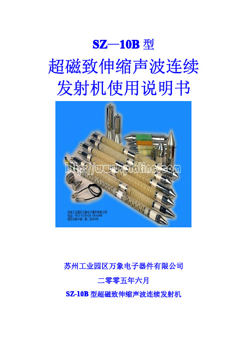
SZ-10B 型超磁致伸缩声波连续发射机售后客户服务中心 联系人: 张晓春 13862580592ቤተ መጻሕፍቲ ባይዱ手机)
售后技术支持热线电话:0512-65042988 售后技术支持热线传真:0512-67253426
孙鹏程 13914955286(手机)
地址:苏州市宏葑新村 39-102 TEL: (0512)65042988 邮编:215002 FAX: (0512)67253426 E-mail:xiaoxians@ 网址:/ 3
2、声波仪和发射机连接及操作说明 ①、按接线图连好设备,使用蓄电池供电时,容量不得低于 20AH。 ②、设备下井前必须清孔,使设备下井顺畅不卡孔。 ③、将声波仪的发射方式设置为单次发射,脉冲宽度设置不大于 80uS(推荐 40uS) ;设置为连续发射时两次发射间隔时间必须大于 5000mS;设置为 外触发时。 ④、应用声波仪同步触发时:合上发射机电源开关,发射电压值在面板上显示,
SZ-10B 型超磁致伸缩声波连续发射机
Ⅲ、一发双收连接图
地址:苏州市宏葑新村 39-102 TEL: (0512)65042988 邮编:215002 FAX: (0512)67253426 E-mail:xiaoxians@ 网址:/ 8
Ⅱ、一发一收连接图
地址:苏州市宏葑新村 39-102 TEL: (0512)65042988 邮编:215002 FAX: (0512)67253426 E-mail:xiaoxians@ 网址:/ 7
苏州工业园区万象电子器件有限公司
苏州工业园区万象电子器件有限公司
SZ-10B 型超磁致伸缩声波连续发射机
一、前言
SZ-10B 型超磁致伸缩声波连续发射机是最近由苏州工业园区万象电 子器件有限公司、中国地质大学、同济大学和中南大学共同研制成功的最 新产品。该发射机采用目前最新技术和材料研制而成,具有声波发射能量 大、频率高、余振小、转换效率高、使用寿命长;且外观设计美观、重量 轻、体积小、抗震性好、有多种保护功能等特点,是目前最理想的声波发射 震源。该产品在试制过程中得到了长江委和华东院大力支持,并提出了许 多宝贵的建议。
Sennheiser Digital 6000 SK 6212 体包发射器说明书

FEATURES• Compact, ultra-small design with ergonomically optimi-zed construction (63 x 47 x 20 mm)• Designed for 12 hours of continuous operation• Made with ultra-light robust metal housing weighingonly 112 grams• Intermodulation-free transmission – permits morechannels even in very narrow frequency spaces thanksto equidistant frequency grid and simple setup• Superb sound and higher dynamic range thanks toSennheiser Digital Audio Codec (SeDAC) and long-ran-ge mode, also found in the Digital 9000 series• Resistant to moisture and sweat• Two detachable clips (0°/90°) for secure fit in anyposition• Exchangeable antenna and battery• Can be used with a variety of lavalier microphones andheadsetsDELIVERY INCLUDES• SK 6212 bodypack transmitter• antenna• clip, vertical• clip, horizontal• quick guide• safety guide• specification and manufacturer declaration sheetThe SK 6212 has been specifically designed to meet thedemands of theatrical performances and broadcast appli-cations. Weighing only 112 grams, it’s ultra-small designmakes every-day use easier for performers, make-upartists and costume designers alike. For audio engineers,the SK 6212 can still be directly operated and controlledvia a display and buttons, and the intermodulation-freetransmission technology is designed for an unbelievable 12hours of continuous operation.It’s robust construction, rounded ergonomic design, andtwo versatile clips ensure the device is comfortable andsecure, whether the user is acting, dancing or singing. Theantennas and batteries are exchangeable and the metalhousing is sealed for sweat resistance.The SK 6212 can be combined with lavalier microphones and headsets. It provides maximum transmission reliability thanks to the legendary ‘long-range mode’, and outstan-ding audio quality thanks to the Sennheiser Digital Audio Codec (SeDAC), also used in the top-class Digital 9000 series. It’s sophisticated transmission electronics generate no disruptive intermodulation, even when there are several transmitters in a very small space. As a result, operation within an equidistant frequency grid is possible. The avai-lable frequency spectrum is used efficiently and remains easy to configure.SYSTEM COMPONENTS• EM 6000 / EM 6000 DANTE• SKM 6000• SK 6000• L 6000PRODUCT VARIANTSSK 6212 A1–A4470.200 − 558.000 MHz Art. no.508513 SK 6212 A5–A8550.000 − 638.000 MHz Art. no.508514 SK 6212 B1–B4630.000 − 713.800 MHz Art. no.508515 SK 6212 A5–A8 US550.000 − 607.800 MHz Art. no.508521 SK 6212 B1–B4 AU630.000 − 693.800 MHz Art. no.508529Frequency range 470.200 to 713.800 MHz Modulation scheme Digital modulation Long Range ModeAudio codecSeDAC (Sennheiser Digital Audio Codec)Switching bandwidth up to 88 MHz Frequency stability < 5 ppm Tuneability25 kHz stepsLower cut-off-frequency (−3 dB)adjustable: 30 Hz, 60 Hz, 80 Hz, 100 Hz, 120 Hz RF output powerstandard mode:15 mW rmslow power mode:3.5 mW rmsAudio frequency response 30 Hz to 20 kHz (-3 dB)Audio Gain Mic: adjustable in 3 dB steps from −6 dB to +42 dB Audio input3-pin audio socket THD(Total harmonic distortion)typ. 0.002%SNR (Signal-to-noise ratio)typ. 113 dB(A)Encryption AES 256Antenna output coaxial socket Operating timetyp 12 h at 25 °C(with BA 62 accupack)Dimensions (H × W × D)approx. 63 × 47 × 20 mm Weightapprox. 112 g (with BA 62 accupack and beltclip)SPECIFICATIONSACCESSORIESBA 62Rechargeable battery Art. no. 508517Clip, horizontal Art. no. 508570Clip, vertical Art. no. 508571Antenna A1-A4Art. no. 508572Antenna A5-A8Art. no. 508573Antenna B1-B4Art. no. 508574MKE 1–4Lavalier microphone, omni-directionalArt. no. 502167MKE 2–4Lavalier microphone, omni-directional)Art. no. 004736MKE 40–4Lavalier microphone, cardioidArt. no. 003579HSP 2Headset microphone, omni-directionalArt. no. 009862HSP 4Headset microphone, cardioidArt. no. 009864SL Headmic 1-4Headset microphone, omni-directional Art. no. 506905MKE Essential Omni Black Lavalier microphone, omni-directionalArt. no. 508251MKE Essential Omni Beige Lavalier microphone, omni-directionalArt. no. 508252HSP Essential Omni Black Headset microphone, omni-directionalArt. no. 508247HSP Essential Omni BeigeHeadset microphone, omni-directionalArt. no. 508248COMPATIBLE WITH• EM 9046 in Long Range mode •EK 6042DIMENSIONSARCHITECT‘S SPECIFICATIONThe bodypack transmitter shall be for use with a companion receiver as part of a true digital wireless RF transmission system. The bodypack transmitter shall operate in the UHF frequency range between 470.200 and 713.800 MHz. Different frequency variants shall be available depending on country-specific regulations.The bodypack shall feature an OLED display showing battery status, the frequency or the channel name, the status of the lock mode, the AES 256 encryption status and warnings. An additional homescreen shall display the AF level only. Remai-ning operating time shall be indicated by both a battery icon and numeric indication in hours and minutes. All transmitter parameters shall be adjustable with function buttons on the device itself or by infrared synchronization via the associated receiver. The function buttons shall be lockable against accidental misuse.The frequency switching bandwidth shall be up to 88 Mhz with a frequency stability of < 5 ppm and a tunability of 25 kHz steps. RF output power shall be switchable between 14 mW rms and 4 mW rms.The transmitter shall feature an LED indicating the operating status when the device is switched on. The LED shall indica-te audio peaks and low battery and shall be defeatable when the device is in lock mode.The transmitter’s microphone input shall utilize a lockable 3-pin audio socket. The AF frequency response shall range from 30 – 20,000 Hz. The lower frequency limit (-3 dB) shall be adjustable between 30 Hz, 60 Hz, 80 Hz, 100 Hz or 120 Hz. The Audio amplification shall be adjustable in steps of 3 dB from -6 dB to +42 dB.The transmitter shall be compatible with microphones for every application: Sennheiser lavalier microphones MKE 1, MKE 2, MKE Essential and MKE 40, Sennheiser headset microphones HSP 2, HSP 4, HSP Essential and SL Headmic 1-4.The transmitter shall be powered by the Sennheiser lithium-polymer rechargeable battery pack BA 62 with a typical operating time of 12 hours. The rechargeable battery pack shall be exchangeable. The housing of the transmitter shall be made of aluminum with a detachable vertical and horizontal belt clip. The antenna shall utilize a coaxial socket and be detachable by the user.Dimensions shall be approximately 63 x 47 x 20 mm. Weight (with battery pack and belt clip) shall be approximately 112 grams. Operating temperature shall range from −10 °C to +50 °C (+14 °F to +122 °F).The bodypack transmitter shall be the Sennheiser SK 6212.Sennheiser electronic GmbH & Co. KG · Am Labor 1 · 30900 Wedemark · Germany · 。
Earthway M20 电动播撒机说明书

12Volt ATVBroadcast SpreaderMODEL #M20 ASSEMBLY INSTRUCTIONS▪ Always wear protective clothing, eye wear, and dust mask to prevent contact with chemicals and other materialsbeing applied with this machine. ▪ Remove any material in the hopper before lifting or detaching this machine from the vehicle.▪ Care must be taken when lifting this machine so as not to cause personal injury or equipment damage. Neverattempt to install this machine to the vehicle alone. Recruit the help of someone to assist when attaching and detaching this machine from the vehicle. ▪Refer to the material packaging or the Material Safety Data Sheet for precautionary measures required whenhandling materials to be applied. Before attaching this machine, consideration must be given to the load capacity of the vehicle. Refer to the owner’s manual of the vehicle for rated load capacity. Be sure to take into account the weight of this machine is 20lbs. and the weight of the material to be placed in the hopper when calculating the total load.Thank you forselecting EarthWay for your spreader needs. Ourproduction team in Northern Indiana takes pride in building thisspreader. Our customer support team is standing ready to ensure your success. Please contact us at to see our full line of commercial, lawn & garden tools.Assembly Instructions:STEP 1: Unpack all parts from shipping carton to ensure no parts are missing. Refer to the exploded view.STEP 2: Install the four (#9) 7/8” Tube plugs onto the ends of the two (#15) Frames with the help of a hammer or someother tool.STEP 3: Determine whether to mount on the front or the back of the luggage rack. Depending on whether the M20 is mounted to the front or rear rack, you will need to install (#4) Control assembly to either the right (#11) or left (#15) Frame tube to allow for use with the non-throttle hand. Wait until the unit is mounted to the Quad before installing the Control.STEP 4: Next install four 1/4-20 x 1-1/2” Carriage bolts (#12) through the Hopper assembly and then through ONE of either side Frame and secure with 1/4-20 Hex Nut (#8).STEP 5: Now position the M20 to the Quad and install theremaining Frame member as outline above in STEP 4. Nowinstall the Control assembly (#4) to the Frame and secure with a1/4-20 x 1-3/4” Carriage bolt (#13) and 1/4-20 Hex Nut (#8) andtighten firmly to allow movement, but not allow the lever tomove unassisted.Now install the M20 on your quad as outlined on the followingpage.KEEP HANDS AWAY FROM ANY SPINNING OBJECT, SHUT-OFF PLATE, SHUT-OFF MECHANISM LINKAGE, AND THE INSIDE OF THE HOPPER, EXTREME INJURY CAN OCCUR.HOW TO OPERATE SAFELY:▪Read, understand, and follow all product label information provided on the material being applied.▪An adjustable solid stop is provided that allows the operator to adjust to the desired opening position on the rate setting control prior to operation of the vehicle. This allows repeatability to the stop without the need to look at the control while operating the vehicle.▪Establish the correct rate and then lock the stop in that position using the thumb wing nut on the setting control. OPERATING INSTRUCTIONS:Before filling hopper, become familiar with the operation of this spreader. (Practice the following steps)▪ Turn the motor switch to the ON POSITION, so that the impeller is turning before going on to the next step.▪ While driving forward pull the lever back to the stop, this opens the shut off plate on the spreader.▪ To stop the flow of material, Push the lever to “0” or closed position, then turn the motor off when finished.▪ When finished empty any remaining material from hopper.▪ Thoroughly wash spreader and allow to dry before storing. A light coating of oil will help prevent corrosion of all metal surfaces.MOUNTING INSTRUCTIONS:Position the M20 on the vehicle so that the impeller is positioned to be ableto spin clear of any part of the vehicle, this will allow a full 180 degreespread pattern. Secure the frame to the mounting location with theenclosed J-Bolts at positions that will secure the spreader so that it will notmove when operating the vehicle. For best results mount the spreader sothat the impeller is as close to the vehicle as possible, but clears any parts onthe vehicle and place the J-Bolts as shown below.Connect the black wire (ground) to the negative (-) post on the battery andthe fused wire to the positive (+) post on the battery.If for any reason the impeller rotates counter clockwise,reverse the battery connection of the spreader. Correctrotation is clockwise.SPREADER CALIBRATION INSTRUCTIONS:▪Loosen stop on the gauge and set to #30▪Open the lever to #30 and make sure that the shut-off is fully open▪Loosen the cable clamp on the bottom of the hopper and slide the outer cable IN/Out until the shut-off is fully OPEN. Tighten the cable clamp and retest.▪Calibration is now complete▪TO CALCULATE THE SETTING:▪Determine how much material is to be applied per 1,000 sq/ft.▪Measure off a distance of 50 feet, preferably on a paved surface such as a parking lot.▪Weigh out enough of the material to be applied to fill the hopper at least half full. Record the weight for future use.▪With the unit mounted on the vehicle and the hopper at least half full of the material to be spread, position the vehicle far enough before the beginning of the 50 foot test area so that the vehicle will achieve the desiredspeed before you reach the starting line.▪Set the rate setting stop at a position that you feel would be an appropriate setting.▪Start the vehicle in motion and as you cross the starting line (of the 50 feet) move the rate lever to the open position against the stop. Take care to be aware of what is going on around you maintaining control of thevehicle.▪Continue from the starting line with the unit spreading the material. As you cross the finish line move the rate lever to the closed position.▪Stop the vehicle and note the width of the spread path that was just completed.▪Return to the start point and empty the remaining material from the hopper into your weighing container and re-weigh.All spare parts listed herein may be ordered direct from the manufacturer. Be sure to give the following information when ordering.1.Model Number2.Part Number3.Part DescriptionYou can contact us by calling (574) 848-7491 to place an order with a credit card, or purchase online at. Questions? Email us at ******************Installation the 77122 3-Sided Deflector Kit requires drilling of the hopper and motor support assembly for fitting.EC DECLARATION OF CONFORMITY(Machinery Directive & ElectromagneticCompatibility Directives)Herewith we declare that the machinery described below is in accordance with the relevant health and safety requirements of the EC Council Directives concerned with Machinery and Electromagnetic Compatibility. No alterations are to be made to the machine without prior consultation and approval of Earthway Products, Inc. otherwise the Declaration may become invalid. This equipment must be commissioned, used and maintained strictly in accordance with the operating and maintenance instructions issued with the machine. Operators must be trained in accordance with the recommendations given in the operating and maintenance instructions issued with the machine.Description of Machine: EarthWay® M20 12-volt Broadcast SpreaderDate of Supply: AS INVOICED DATERelevant EC Council Directives:Machine Directives 89/392/EEC and subsequent amendments.Electromagnetic compatibility Directive 89/336/EEC and subsequent amendments.DO NOT RETURN TO DEALER FOR REPAIR CUSTOMER SERVICE574.848.7491 | ******************** | | 1009 Maple Street, Bristol, IN 46507 ONE YEAR WARRANTYEarthWay Products, Inc. warrants this product free of defects in original workmanship and materials for a period of one year to the end user with the original purchase receipt. If a manufacturing non-conformance is found, EarthWay Products, Inc. at its discretion will repair or replace the part(s)/product at no charge provided the failure is not the result of incorrect installation, mishandling, misuse, tampering, or normal wear and tear as determined by EarthWay.EarthWay at its discretion may require that the part(s) or product be returned along with the original purchase receipt for examination and compliance with the terms of this warranty. Do not return any product without first receiving authorization from EarthWay Products, Inc.Toseekremedyunderthiswarranty,contactEarthWayProducts,Inc.at574-848-7491,***************************** EarthWay Products, Inc. 1009 Maple Street, Bristol, IN 46507 and describe the nature of the manufacturing defect. SPECIFIC LIMITATIONS: This warranty covers only the part(s) or product; any labor charges associated with repair or replacement of non-conformances are specifically excluded. Due to the corrosive nature of most fertilizers and ice melt products, EarthWay Products, Inc. makes no warranty against and specifically excludes part(s) or product degradation or failure due to corrosion or its effects.。
Antari Z-Stream 雾机用户手册说明书

1Z-StreamFog Machine User ManualEnglish© 2014 Antari Lighting and Effects Ltd.234Thank you for choosing the Z-Stream. You now own a durable and powerful state-of-the-art machine. Prior to use, we suggest that you carefully read all of the instructions. By following the suggestions found in this user manual, you can look forward to exceptional performance from your Z-Stream fog machine for years to come.Please follow these operation, safety and maintenance instructions to ensurea long and safe life for your fog machine.Z-Stream Power: AC 120V/60Hz 230V/50HzHeater: 1000W Fuse: 120VAC – F10A/250V230VAC – F5A/250VWarm-up time: 5.5 minutesOutput: 10000 cuft/minTank capacity: 1.35 litreDimensions: 385x 270 x 247 mmWeight: 5.8 kgDanger of electric shock▪Keep this device dry.▪For inside use only. Not designed for outside use.▪For the 110V models, use 3-prong grounded electrical outlet only. Prior to use take care to determine that the unit is installed at the rated voltage.▪Always unplug your Z-Stream fog machine before filling its tank.▪Keep fog machine upright.▪Turn off or unplug when not in use.▪This machine is not water- or splash-proof. If moisture, water, or fog liquid gets inside the housing, immediately unplug the unit and contact a service technician or your dealer before using it again. ▪No user serviceable parts inside. Refer to your dealer or other qualified service personnel.Danger of burns▪For adult use only. Fog machine must be installed out of the reach of children. Never leave the unit running unattended.▪Keep nozzle at least 50 cm (20 in.) away from contact with anything while in operation.▪The fog vapour at point of release is under pressure and is extremely hot .▪Never aim the output nozzle directly at people.▪Fog machine output is very hot. Avoid coming within 50 cm of the output nozzle during operation. ▪Locate the fog machine in a well-ventilated area. Never cover the unit’s vents. In order to guarantee adequate ventilation, allow a free air space of at least 20 cm around the sides and top of the unit.5▪Never aim the output nozzle at open flames.▪The output nozzle becomes very hot during operation (300 degrees C). Keep flammable materials at least 50 cm away from the nozzle.▪Always allow your Z-Stream fog machine to cool down before attempting to clean or service it.Danger of explosion▪Never add flammable liquids of any kind (oil, gas, perfume) to the fog liquid.▪Use only the high-quality, water-based fog liquid that your dealer recommends. Other fog liquids may cause poor effect fog, clogging and “spitting” of unevaporated liquid.▪Always make sure there is sufficient liquid in the fog liquid tank. Operating this unit without liquid can cause damage to the pump and the heater.▪If your Z-Stream fog machine fails to work properly, discontinue use immediately. Drain all fog liquid from the tank, pack the unit securely (preferably in the original packing materials), and return it to your dealer for inspection.▪Always drain tank before shipping or transporting this unit.▪If fog liquid comes in contact with skin or eyes, rinse thoroughly with water. Never drink fog liquid.If ingest accidently and feel not well, call a doctor immediately.Open the shipping carton and check that all equipment necessary to operate the system has arrived intact. In addition to the Z-Stream fog machine, you should receive the following items:1. VR-1T wired timer remote2. 1.35 Liters liquid tank for Z-Stream▪Before beginning initial setup of your Z-Stream fog machine, make sure that there is no evident damage caused by transportation.▪In the event that the unit’s housing or cab le is damaged, do not plug it and do not attempt to use it before contacting your dealer for assistance.6▪Remove all packing materials from the fog machine. Check that all foam and plastic padding is removed, especially in the nozzle area.▪Fill with high-quality water-based fog fluid. Any other types of fluid can damage the unit. When filled, place cap back on the liquid tank.▪Firmly connect the remote control to the proper input on the rear of the machine.▪Plug power cord into a grounded electrical outlet. Then turn on the power switch on the rear of the unit. The machine starts to warm up right away. At the same time, the “Ready” (Green) and“Power” (Red) lamps on the timer remote control will flash. When warm-up is complete the Green and Red lamps will stay lit.▪To emit fog, press the Green button on the remote and hold for the desired length of time.▪The output will stop when the unit needs to reheat, and the “Ready” (Green) and “Power” (Red) lamps on the timer remote control will flash.▪To activate the timer function, turn the knob from off to on and adjust the knob to the length of time for “INTERVAL” needed.▪When the timer function is activated, the “Timer” (Yellow) lamp will be on and the “OUTPUT” time is fixed to 15 seconds.▪VR-1T: 3 meter wire timer remote controller with 1/4 inch stereo plug.7Z-50 (Optional): Wireless remote controller with 6,3 mm jack plug. Operation is possible up to a distance of 50 meters. Keep the red button pressed for fogging.Do not allow the fog liquid to become contaminated. Always place back both the caps on the fog liquid tank and the fog machine liquid tank immediately after filling.8After every 40 hours of operation, it is recommended to run distilled water through the system to prevent the heater clog.Cleaning your fog machine regularly will help reduce costly parts replacement and repaircharges.Always monitor tank fluid level as you are fogging. Running a fog machine without fluid can permanently damage the unit. If you experience low output, pump noise or no output at all, unplug immediately. Check fluid level, the external fuse, remote connection, and power from the wall. If all of the above appears to be O.K., plug the unit again.If fog does not come out after pressing the remote button for 30 seconds, check the tube attached to the tank to make sure there is fluid going through inside.If you are unable to determine the cause of the problem, do not simply continue pressing the remote button, as this may damage the machine. Return the machine to your dealer for inspection.∙All fog machines develop condensation around the output nozzle. Because this may result in some moisture accumulation on the surface below the output nozzle, consider thiscondensation when installing your machine.∙Fog machines may spit small amounts of fog occasionally during operation and for a minute or so after being turned off.∙Z-Stream fog machine has a heating cycle after bursts of fog so the machine stops fogging fora short period in order to reheat. During this time no fog can be produced.∙Only use Antari fog liquids.Save these instructions9___________________________________________________________________________________________________________________________________________________________________________________________________________________________________________________________________________________________________________________________________________________________________________________________________________________________________________________________________________________________________________________________________________________________________________________________________________________________________________________________________________________________________________________________________________________________________________________________________________10___________________________________________________________________________________________________________________________________________________________________________________________________________________________________________________________________________________________________________________________________________________________________________________________________________________________________________________________________________________________________________________________________________________________________________________________________________________________________________________________________________________________________________________________________________________________________________________________________________11C08I28001-ELA12。
肥皂发型机说明书

116286 Spring, Seat-Cap
25
116287 Spring, Cap
26
Cap, Brush Holder
3184212 Black
27 W10068260 Screw
28 W10119326 Control Plate Assembly
29 W10330804 Governor Assembly
29 8533914 Washer, Lock
30 9708652 Screw
31 W11134949 Screw
32 W10903540 Gear, Pinion
33 9706090 Washer
34
Planetary
(Refer to Color Variation Parts Page)
35
240285 Ring, Planetary Drip
19 W10380496 Brush, Cap and Spring
20 9707926 Screw, Set
21 4162546 Brush Holder Assembly
22 3179908 Housing, Brush Holder
23
240680 Insert, Brush Holder
24
Illus. No. Part No. Description
Illus. No. Part No. Description
Illus. No. Part No. Description
1
Gearcase Motor
Housing
(Refer to Color Variation Parts Page)
Illus. No. Part No. Description
ADJ Entourage Touring Fazer烟霰机说明书

American DJ Entourage Touring FazerA hazy atmosphere is crucial for making a lightshow come to life; so if you’re involved in lighting production for anything from large-scale concerts to smaller corporate events, nightclubs to church sanctuaries, a reliable and powerful fog/haze machine is essential. That is where the new ADJ Entourage comes in; this professional-grade ‘faze’ machine generates a massive amount of lightshow-enhancing fog from water-based fluid, but spread out into a fine hazy effect rather than the intense blast created by a regular fog machine.Entourage at a Glance:• 1500W mobile DMX FazeMachine• LCD Function Display withbuilt-in remote• Quick Warm-up time: 45Seconds• Output: 15,000 cubic ft. permin• PowerCon Input• Uses water based fog fluidEquipped with a powerful 1,500W heater, the Entourage offers a vast output potential of 15,000 cubic ft. per minute, making it ideal for large stages and venues. It also boasts a very speedy warm-up time of just 45 seconds, meaning that atmospheric faze can be generated whenever, as well as wherever, it is required.Running on regular water-based fog fluid, the Entourage first creates fog by heating the fluid and then dissipates it evenly using a powerful in-built fan. The output is then directed through a variable-angled hopper which sends the faze upwards and outwards. This gives venues and production companies the benefits of both low-cost water-based fog fluid and a light-enhancing haze-like atmosphere rather than the heavy, smoky atmosphere associated with regular fog machines.Capable of continuous output if required, the Entourage is also fitted with an easy-to-read LCD display interface that facilitates simple configuration of an in-built timer. This allows bursts of variable intensity and length to be programmed to occur at regular intervals. The machine can also be controlled by DMX using a choice of three different modes: 1, 2 or 5 channel.For easy integration into any professional lightingsystem, both 3-pin and 5-pin input and outputsockets are provided for DMX. The unit is alsoequipped with a professional locking PowerConmains input socket to prevent the power cordbeing pulled out accidentally.Further enhancing the Entourage’sattractiveness for event production and touringapplications, the machine is actually built into aheavy-duty road case. This means that no additional storage and transportation case is required and setting up the Entourage is as simple as unhooking two butterfly clips, removing the lid and connecting mains power. The case is fitted with a heat vent, allowing the machine to run safely from within its protective shell. It is also fitted with rubber feet, allowing it to stand directly on a stage without slipping or scratching the surface, and is large enough to accommodate the mach ine’s significant 5.6-liter external fluid tank.Measuring 21” x 15.25” x 9.75” (533 x 387 x 249mm) the Entourage is a relatively compact machine that doesn’t take up unnecessary space, both in use on stage and in transit or storage. Weighing 47 lbs. (21.3 kg.) it is a significant piece of equipment, but one that can be comfortably carried and maneuvered single-handedly.The right atmosphere is essential for creating an impressive lightshow, and the ADJ Entourage is ideal for filling even the largest of spaces with a fine mist of beam-enhancing fog. Thanks to its integrated road case, the unit is also easily portable and it’s varied operating and control modes mean that it is flexible enough to fit into any temporary or permanent installation. If you’re looking for a powerful, reliable and feature-packed source of atmospheric faze, why not add the ADJ Entourage to your entourage of lighting equipment?Specifications•1500W mobile DMX Faze Machine• 3 DMX Channel Modes; 1/2/4• LCD Function Display with b uilt-in remote with Fog Timer, Continuous Fogging, & Manual Fogging•Warm-up time: 45 Seconds•Output: 15,000 cubic ft. per min•External fog fluid tank: 5.6 Liter• Fluid Consumption: Max. Output 9ml/min, mini. Output 0.45ml/min•3-pin & 5-pin DMX In/Out•PowerCon Input•Only use high quality, water based fog fluid• Dimensions (LxWxH): 21” x 15.25” x 9.75” / 533x387x249mm• Weight: 47 lbs. / 21.3 kg.。
- 1、下载文档前请自行甄别文档内容的完整性,平台不提供额外的编辑、内容补充、找答案等附加服务。
- 2、"仅部分预览"的文档,不可在线预览部分如存在完整性等问题,可反馈申请退款(可完整预览的文档不适用该条件!)。
- 3、如文档侵犯您的权益,请联系客服反馈,我们会尽快为您处理(人工客服工作时间:9:00-18:30)。
ZS型系列水泥散装机
使用说明书
中华人民共和国
唐山忠义机械制造有限公司地址: 河北省唐山市高新技术开发区南开道北
电话: ( 0315) 3853580 3855782
传真: ( 0315) 3857682
邮编: 063020
E-mail:
ZS型系列水泥散装机使用说明书
目录
一、前言
二、用途及使用范围
三、主要规格及技术参数
四、结构及工作原理
五、主要设备及配置
六、设备安装
七、调试、运转
八、使用注意事项与维护
九、故障分析及处理措施
十、润滑
十一、电气
十二、订货说明
一、前言
ZS型系列水泥散装机是唐山忠义机械制造有限公司根据国家发展水泥散装产业政策之需要,综合国内外各种物料散装设备的特点,自行研制的产品。
本产品经河北省矿山机械产品质量监督站检验, 技术性能和质量符合JC/T608-1995行业标准。
本产品设计合理、结构紧凑、可与库底、库侧卸料装置组合, 具有电动升降、自动定位、料满自动报警停机等功能, 生产效率高、操作简单、维修方便, 是水泥散装的理想设备。
产品型号说明
ZS ——
安装结构型式代号: Z 直通式
F 非直通式
入料型式代号: KD 库底卸料
KC 库侧卸料
散装能力: t/h
分类代号: G 固定式
Y 移动式
水泥散装机代号
例: 库底卸料直通式100t/h固定式水泥散装机, 型号为ZSG100-KD-Z
二、用途及使用范围
1、用途:
本系列水泥散装机主要用于水泥生产厂水泥物料的汽、火车散装, 同时, 也能够用于其它行业粉粒物料装车, 如粉煤灰、氧化铝等。
2、适用范围:
(1)供电电源: AC 50Hz 3N 380V±10%
(2)使用条件:
a、水泥含水量不应超过1%;
b、环境温度: -10℃~40℃;
c、相对湿度: <90% RH
d、海拔高度: ≤ m
三、主要规格及技术参数( 见下表)
1
主要规格及技术参数
四、结构及工作原理
1、主要结构:
ZS型系列水泥散装机分为固定式和移动式两种类型。
每种水泥散装机根据入料型式不同, 可分别与库底、库侧卸料装置相接, 组成库底卸料水泥散装机和库侧卸料水泥散装机; 还可组成两库合一固定式水泥散装机。
同时, 根据用户现场情况, 可分别采用直通式和非直通式的安装方式, 满足用户实际需要。
固定式水泥散装机由机座、电机、减速机、卷扬装置、内外伸缩套筒、散装头、压力控制器、风机、电控柜等组成。
移动式水泥散装机是将固定式水泥散装机安装在行走车上, 车上有料仓, 经过密封装置与入料机构相接, 确保在行走过程中既能入料, 又不会将物料泄漏。
适合对汽车、火车的散装作业。
2、工作原理
(1)定位:
散装车开至固定式水泥散装机下方, 使贮料罐进料口位于散装头的正下方, 开启升降装置, 使与双层伸缩软管相连的散装头下落贮料罐进料口后, 由行程控制机构自动切断电源, 完成定位。
若散装头不在贮料灌进料口内, 即不是灌装位置时, 按动其它装料按钮不起作用, 拒绝灌装卸料。
移动式水泥散装机有600mm水平行程, 可经过水泥散装机的移动进行定位。
2
(2)卸料:
散装头降至灌装位置后, 按顺序启动散装机全部设备: 库内取料的罗茨风机、空气输送斜槽风机、气动开关阀、除尘器和料满控制系统, 开始灌装。
库侧卸料时, 安装在库内开式充气斜槽向库内充气后, 水泥在库中以流态化卸出, 使卸料流量稳定, 并兼有库内混料和破拱的综合作用。
松动流化的水泥物料经充气式螺旋闸门、气动开关阀、空气输送斜槽、连接管进入散装机, 经过散装头流入散装车贮料罐内。
( 库底卸料直通式为手动螺旋闸门、气动回转阀, 无空气输送斜槽)
气动开关阀可分为有无充气室两种结构形式, 它经过气动执行机构进行阀芯的启、闭, 完成物料的卸料和截止。
气动执行机构开闭迅速、结构简单、工作可靠, 瞬间控制灌装过程的开与停。
除尘器接到两伸缩袋之间的收尘接口, 接收由气体输送和散装车内排出的烟尘并进行收尘, 以保证工作环境无扬尘和烟气, 除尘后的回灰可返回到水泥散装机中, 继续使用。
该过程所有设备动作顺序均采用联锁控制。
( 3) 料位控制:
当贮料罐内的水泥物料达到灌装高度时, 与压力控制器相连并安装在散装头顶端的风管被水泥埋入, 风压增加, 压力控制器动作, 同时发出料满控制信号, 关闭气动开关阀切断料源, 停止供料, 使灌装过程立即停止。
与此同时, 延时继电器接通, 除尘器继续收尘。
( 4) 伸缩袋的提升:
当延时时间到后, 控制柜内的电铃接通, 表示已完成一次灌装循环, 提升伸缩袋, 让散装车开走。
五、主要设备及配置
1、主要单机设备
( 1) 开式充气斜槽( 又称给料器)
它可分为库底和库侧两种, 一般由用户自备。
如需购置时, 应在合同中注明。
所需风源设备罗茨风机, 风压为0.04—0.08MPa, 由用户自备。
( 2) 手动螺旋闸门
手动螺旋闸门根据安装位置分为两种, 一种为水平安装, 无充气室, 适用
3
于库底卸料, 与库底给料器下法兰相接; 一种为垂直安装的充气式手动螺旋闸门, 适用于库侧卸料, 与库侧给料器连接法兰相接。
手动螺旋闸门工作时, 为常开状态, 当设备检修或发生异常情况时, 用于切断料源, 停止供料。
手动螺旋闸门普通型为LZ-300, 充气式为QLZ-300, 分别适用于库底、库侧卸料。
(3)气动开关阀
气动开关阀是经过气动执行机构使扇形阀芯或圆筒形阀芯回转一定角度, 使其开启和关闭, 起到导通和截断物料的作用。
气动开关阀动作迅速, 安全可靠, 结构简单, 维修量小。
气动开关阀需要有工作压力为0.4—0.6MPa的压缩空气供给执行机构做气源, 此气源由用户自备。
气动开关阀通电时, 气阀导通使气缸打开阀门, 断电后气缸自动复位关闭阀门。
气动开关阀有FHQ300、 FKQ300两种型号, 可分别用于库底、库侧卸料。
(4)电动流量控制阀
电动流量控制阀是经过角行程电动执行器接受来自变送单元或调节单元的统一标准信号电流, 并自动地将其变成与之对应的转角位移来调节回转阀芯的开度, 从而达到调节流量之目的。
由于三角形开口在阀芯回转时经过阀内物料流量具有良好的调节性, 故一般电动流量控制阀阀芯开口为三角形。
电动流量控制阀有FLD250、 FLD300两种型号, 分别用于库底和库侧卸料。
此设备应根据工艺布置设计进行选用。
一般情况可不配置。