中间件Niagara的使用说明文档
niagara中间件软件安装及测试文档

6测试6.1硬件测试用万用表测试左右扇面的24V+与24VG是否短路用万用表测试左右扇面的5V与5VG是否短路电源没有短路即可上电,若有短路,排查短路原因。
6.2软件测试6.2.1软件安装1、将U盘中的文件拷贝到一体机D盘下。
2、安装IndyTool v2.3.0,找到D:\一体机软件\R2000\IndyTool中的图标,双击进行安装。
3、将D:\一体机软件\F860光盘文件\app中的UHF.exe,UHFD.exe,UHFExample.exe,建立桌面快捷方式。
4、安装Niagara,运行Niagara4.1在D盘下建立文件夹作为安装Niagara路径4.2解压到’Niagara相关’文件夹下,参考Readme.txt文档。
4.3在D: \一体机软件\Niagara 相关\Niagara_AX_Developer-3.5.30中,双击图标,开始安装点击下一步,选yes,点下一步路径选择为D:\Niagara\Niagara-3.5.30,点下一步:选择select All选下一步:点下一步:点完成,用注册码激活软件将D:\一体机软件目录下的modules文件夹粘贴到D:\niagara\Niagara-3.5.30目录下的modules中;将D:\一体机软件目录下的demo文件夹覆盖D:\niagara\Niagara-3.5.30\stations目录下的demo 文件。
Niagara软件安装完毕。
5、安装Java JDK:找到D:\一体机软件\HerculesSetup.exe下的双击进行安装。
6、将D:\一体机软件\搜索配置设备创建到桌面。
6.2.2软件配置6.2.2.1路由器配置步骤:1、用一条网线将路由器的一个LAN口与电脑的网口连接。
2、打开电脑上的浏览器,输入http://192.168.1.1/后,得到如下页面:查看路由器上的用户名和密码(注意,该用户名和密码为出厂初始密码,在路由器背面有标注)输入到上图中。
Niagara&Sedona

作者:王通生
目录
一、物联网及Niagara在物联网中的位置 一、物联网及Niagara在物联网中的位置 二、Niagara概念 二、Niagara概念 三、Sedona概念 三、Sedona概念 四、Sedona Niagara的关系 四、Sedona与Niagara的关系 Sedona与
是小型设施,远程站点和大型项目分布式监控理想选择 64 MB RAM/64 MB Flash, (2) 10/100 MB Ethernet ports, (1)RS-485 serial port, (1) RS-232 serial port, NDIO port and (2)communication card option slots. Standard features include Niagara station and Web User Interface. Standard driversinclude oBIX Client/Server and Niagara Network (Fox) Client/Server. The JACE® -2 is designed for DIN rail mounting.
通过以太网或者远程基于互联网或拨号modem, JACE-6可以为标准Web浏览器提供数据和丰富的图 形界面 128 MB RAM/128 MB Flash, (2)10/100 MB Ethernet ports, (1) RS-485 serial port, (1) RS-232 serial port, NDIO port and (2) communication card option slots. Standard features include Niagara station and Web User Interface. Standard drivers include oBIX Client/Server and Niagara Network (Fox) Client/Server. The JACE®-6 is designed for DIN rail mounting.
AM2 Niagara产品说明说明书

AM2 Niagara products feature a multiprocessor architec-ture, which guarantees that call volume is not affected by the number of operating channels or the nature of the tests that the user chooses to perform. Extensive use of high speed microprocessors and Digital Signal Processors (DSPs) make AM2 Niagara versatile, accurate and fast.All tone detectors are based on DSPs. Never needing cali-bration, AM2 Niagara systems will last well into the next generation of switching systems.To maintain the maximum level of performance, function-ality and flexibility, every AM2 Niagara is powered by a 32-bit RISC processor, controlled via user defined scripts and protocols and managed via FeatureCall, a Windows based graphical user interface. In addition, every line or channel in an AM2 Niagara is served by “local” DSPs to identify call progress tones, detect digits and to verify the voice path after a connection has been established. The combination of these capabilities allows the user of AM2Niagara to create the complex call testing applications neces-sary to develop and test today’s communication systems and applications.18B00021B-1995MLeading Edge TechnologyThe Ameritec Commitment Ameritec Corporation has been manufacturing Bulk Call Generators for testing switches with analog, PCM, ISDN and SS7 interfaces, as well as other telecommunications test equipment, for over fifteen years. Ameritec test equipment is used by major telecommunication equipment manufacturers,telephone companies, network service providers and PTTs worldwide. Ameritec is an independent test equipment manufacturer, not owned or affiliated with any switch manufacturers or service providers -- your assurance of neutral and unbiased testing.Portable Call GeneratorsAM2-A Analog AM2-D CASAM2-B ISDN BRIAM2-DX ISDN-PRI AM2-P P-Phone (EBS)AM2-S7SS7AM2-Niagara¨760 Arrow Grand Circle ¥ Covina CA 91722 ¥ +626 915 5441 ¥ Advanced Test Equipment Rentals 800-404-ATEC (2832)®Es t a b l i s h e d 1981T1/E1Graphical User InterfaceAmeritec’s AM2 Niagara ®family of products is AM2 Niagara units are ideally suited for testing complex, interactiveSuch test applications include:•Central Office or PBX Switches and Networks ••Signaling:All interface specific signaling functions supported through Testing Your ApplicationsTest configurations can, via Ameritec’s FeatureCall I n t r o d u c t i o nT e s t i n g A p p l i c a t i o n sM o d e l sCapabilities in Call Scripts include:The AM2 Niagara has the flexibility to serve a wide range of telephony testing requirements including both 21Each AM2 Niagara comes with FeatureCall, a Windows based Graphical User Interface (GUI) that provides control and management, via a personal computer, of one or more Ameritec Call Generators via a TCP/IP LAN or a single RS232 port. FeatureCall provides the user with simple, easy to use tools that allow you to:simple stepsCreate reports that verify is runningTesting complex telephony applications requires you to develop many test cases. Limited programmability or learning a programming language used to be your choices - until ScriptMate! ScriptMate is a graphical tool that allows youCall Scripts are templatesdefining the actions of a singlecaller. The Call Script defines calling patterns, voice path con-firmation requirements and the supplemental tones and digits used All AM2 Niagaras are furnished with front panel controls and FeatureCall, Ameritec’s Windows basedGraphical User Interface (GUI)that provides control for test applications with a single AM2 or multiple units via an RS232 port or over a TCP/IP LAN. FeatureCall provides an easy method to configure units,create tests parameters and run test cases.Customizing Call Scripts & ProtocolsThe AM2 allows users to develop scripts and protocols to meet their specific needs. Custom scripts and protocols may be developed by simply modifying the ones supplied with the unit, or new ones may be developed from the ground up using available tools.Call Scripts are developed by using either ScriptMate, Ameritec’s Graphical test script generator tool or in a standard Text Editor. Scripts can be automati-cally downloaded to a unit through FeatureCall’s Call Setup Script window.Statistics & Error MessagesStatistics are automatically accumulated in the unit.Reports include totals for each line/channel, the number of errors recorded as well as totals for the system. The amount of statistical information reported Call Scripts (Template)Programs Statistics & Error MessagesThis option provides up to 64 two second recorded messages for AM2 Niagara Models AM2-A, AM2-B,AM2-D, AM2-De and AM2-PVoice Replay Option:Adds V oP measurement capabilities to all models except AM2-B, AM2-PVoice Over Packet Option:Real Time Error •Displayed or printed as they occur Reports:•Details of the last 100 errors are stored •Error reports include: type, the line(s) or channel(s), time•Error types recognized and reported:•Slow dial tone (AM2-A only)•No dial tone (AM2-A only)•Slow start (Except AM2-A)•No start (Except AM2-A)•No alert tone•Path or B-channel confirmation failed •No answer signal•Ring time-out (Except AM2-B andAM2-DX/DXe)•Busy•Protocol cause values (ISDN-BRI,ISDN-PRI & SS7 only)•Custom code report count(programmable in test script)All Models Available in CE Compatible VersionsThe AM2-A Analog Call Generator provides line interfaces for 64 analog lines and 160 total lines with the AM2E-A Expansion Unit.Provides Analog Display Service Interface(ADSI)/Caller ID test functionality on AM2 NiagaraModel AM2-A.AM2-A and AM2E-A Specifications:ADSI Option:The AM2-P Analog Call Generator provides lineinterfaces for 16 to 64 analog lines.AM2-P Specifications:The AM2-B Basic Rate ISDN FeatureCall Generator provides the line interfaces for 32 BRI/BRA-ISDN U-Interface (2B1Q) lines.The AM2-D Digital Call Generator provides the inter-face for one to four 1.544 Mbps T1 or one to four 2.048 Mbps E1 trunks (AM2-De).AM2-B Specifications:AM2-D and AM2-De Specifications:The AM2-S7 Call Generator provides the interface for four 1.544 Mbps CCS T1 or one to four 2.048Mbps CCS E1 trunks (AM2-S7e).AM2-S7 and AM2-S7e SpecificationsThe AM2-DX Primary Rate ISDN Call Generator provides the interface for one to four 1.544 Mbps CCS T1 or one to four 2.048 Mbps CCS E1 trunks (AM2-DXe).AM2-DX and AM2-DXe Specifications。
NiagaraAX封装Program组件使用说明
介绍
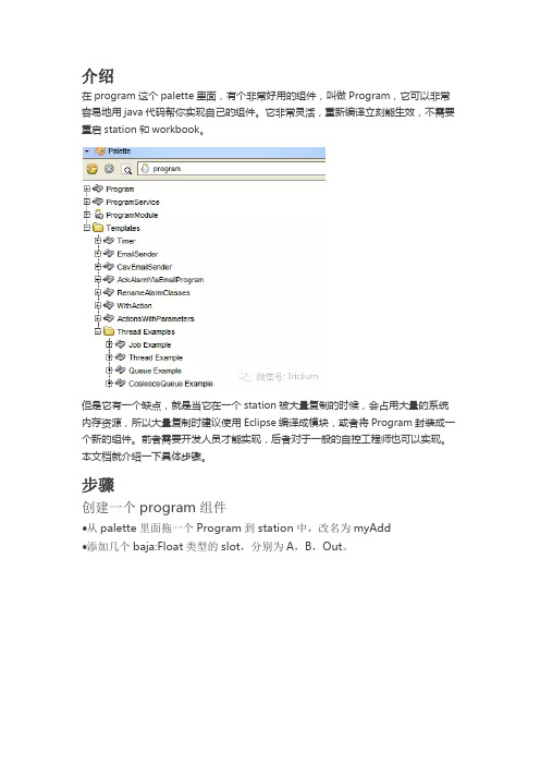
在program这个palette里面,有个非常好用的组件,叫做Program,它可以非常容易地用java代码帮你实现自己的组件。
它非常灵活,重新编译立刻能生效,不需要重启station和workbook。
但是它有一个缺点,就是当它在一个station被大量复制的时候,会占用大量的系统内存资源,所以大量复制时建议使用Eclipse编译成模块,或者将Program封装成一个新的组件。
前者需要开发人员才能实现,后者对于一般的自控工程师也可以实现。
本文档就介绍一下具体步骤。
步骤
创建一个program组件
•从palette里面拖一个Program到station中,改名为myAdd
•添加几个baja:Float类型的slot,分别为A,B,Out。
•写代码,实现A+B=Out
•点击工具栏的编译按钮
•右键点击该模块,复制到剪切板。
使用ProgramModule
在Palette里面,双击ProgramModule。
编辑ProgramModule Builder视图,填写下面的信息,这里将模块名称命名为MartinModule。
并把刚才的模块粘贴过来,改名为MyAdd。
然后点击Build按钮,完成编译。
验证
重启station,重启workbench。
在workbench的Palette里面,打开MartinModule,将MyAdd拖入station中,就可以看到运行结果。
Niagara Framework 介绍(一)

Wireless Protocols
Remote I/O
Modbus RS-485 MSTP RS-485
Ethernet Protocols
LON Devices MSTP Devices Modbus Devices
Modbus TCP, OPC and others IP Controllers
FOX:1911
Device Model
Niagara D:3011
Niagara Station(App)
NRE(Niagara Running Environment)
Niagara Deamon JVM: Hotspot / IMB J9 OS: QNX / Windows / Linux
Hardware: x86 PPC
Niagara Framework——连接任何协议,设备,网络
未来可以智能联接的设备有接近600亿,甚至更多的智能设备将在未来10年内被接入到网络 Niagara 和Sedona平台可以接入任何协议,任何设备,任何网络, 并轻松与企业管理系统进行一体 化应用,为企业创造商业价值…
Niagara Framework 连接任何协议和网络、数据库
Niagara的优势——基于平台的增值服务
OEM 产品开发
SI Solutions 系统集成
统一的开发.应用平台
• NiagaraAX Framework®是一个统一的开发.应用平台,可以方便地创建 基于互联网的产品和应用功能。
•作为一个可复用的通用软件平台,NiagaraAX Framework®能够帮助您 在公共平台上快速、方便、低成本地开发稳定的各种智能应用、智能设 备、以及设备-企业级解决方案。
Niagara讲解要点
1、引言随着当今社会的高速发展,嵌入式、智能设备和系统已经遍及我们的周围,它们隐藏在我们工作和生活的各个角落,负责从环境控制(温度、湿度、空气质量、照度),到安全(消防安防报警、通道控制、视频监视),到测量(水、电、燃气),到服务(电梯、垃圾处理,热水器),甚至是我们所使用的商品的生产线上。
智能设备和系统越来越多的影响着我们的世界。
如今的设备的智能化越来越高,能力也越来越强,但是我们真正发挥出它们的所有能力了吗?它们告诉我们它们在做什么了吗?它们检测到某些情况了吗?它们决定做什么或不做什么吗?它们知道彼此的存在并相互配合了吗?现实是这些嵌入式的设备,不像PC 或者Server,可以支持图形操作系统的各种应用,并不容易相互通信,嵌入式设备大都使用成百上千的不同的,非IP 的通信协议,其中只有一部分被认定为标准。
和我们的PC 和Server 不同的是,用户投资这些设备会保留10 到15 年,而非 3 到 5 年。
也就是说这些设备会跟随我们相当长的时间,如何在不更换这些设备的情况下,让它们协调工作并且更好的管理是摆在每一个集成商和用户面前的关键问题。
正如“团结就是力量”,当信息被分享并相互关联时,智能化的效果就会大大提升,麦特卡夫定律(互联网奠基人)正好说明了这一点,“ 网络价值同网络连接数量的平方成正比”,如何让各种智能设备连接IP 网络并融入上层的应用系统,也就是我们所提出的创建智能设备的各种应用,就变得至关重要。
Tridium 公司所研发的Niagara AX 平台正是设计用于解决设备连接应用的软件框架平台。
2、Niagara AX 简介NiagaraAX 是一种应用框架,或者说是软件框架,特别设计用于应对智能设备所带来的各种挑战,包括设备连接到企业级的应用,支持互联网的产品和基于互联网自动化系统的开发。
应用框架是一个软件工程中的概念,不同于普通的软件,它是用于实现某应用领域通用完备功能的底层服务,使用这种框架的编程人员可以在一个通用功能已经实现的基础上开始具体的产品和系统开发。
niagara中间件软件安装及测试文档

6测试6.1硬件测试用万用表测试左右扇面的 24V+与24VG 是否短路 用万用表测试左右扇面的 5V 与5VG 是否短路 电源没有短路即可上电,若有短路,排查短路原因。
6.2软件测试 6.2.1软件安装1、将U 盘中的文件拷贝到一体机 D 盘下。
2、安装 IndyTool V2.3.0,找到 双击进行安装。
3、将 一体机软件 \F860 光盘文件 \app 中的 UHF.exe , UHFD.exe , UHFExample.exe 桌面快捷方式。
4、安装 Niagara ,运行 Niagara 4.3 在 D: 一体机软件 \Niagara 相关 \Niagara_AX_Developer-3.5.30 中,一体机软件\R2000\lndyTool 中的图标 4.1在D 盘下建立文件夹作为安装Niagara 路径Readme.txt 文档。
图标,开始安装,建立 4.2解压 'Niagara 相关'文件夹下,点击下一步,Please read the folto^ing license agreen^enr End U?er License Agreement 曲也 1 反 2005 [M 曲 be updat&d from time by T ridiurri]IRIDIUM, INC. fTRIDIUM")HAS DEVELOPED A STAhOAFSDIZED ARCHITECTURE AHD RELATED SOFTWARE FOR IMTE FrCON ME CUN G DEVICES AND CONTROLLERS TRIDILJH IS WILLING TO PR0VID "LIMITED LICENSE 0FTH EAECHITE CTURE AND SOFTWARE (THE "NIAGARA FRAMEWORK") TO ?0U ONLY ON THE COMDITION THAT YOU ACCEPT ALL OF THE TERMS IN THIS AGREEMENT.PLEASE READ THE TERMSAND CONDITIONS OF THIS AGREEMENT CAREFULLY BEFORE OLICKING ON THE "I ACCEPT J1 BUTTON. BY COCKING ON THE"I ACCEPT" BUTTON YOU ACKNOWLEDGE THAT YOU HAVE FiEAD THIS AGREEMENT AND AGREE TO SE BOUND BY ITS TERMSAND CONDITIONS.匚 LI 匚 <DN THED Q you ^Gtept thi? ^areerrient?选yes,点下一步、• Papered(Wiamra、一/ OF»!AMEWOPlt fcInstallationWefcome to the NidgaraAXuevelopBr Package 15 30 Installation F\oca?$This program will in si alfthe Niagara 朋 D eveloper 3.5.30 software orto voui computer.guild 3L5.30 MOct2(T10下一古no >取消License Agreement<上一母広)下一母的)>惡消gmpeul耆Apu id圧laqiar^'AK Deve toper Pac.*rawered byFRAMEWORK "3D^lFiation' FolderD : VN iagaraVH iag ara-3.5 30DefaultQtoupjse...Space Required Space A.v^4able* T his insknee of WotkHace 朋 will be iced 日$ an installation tool (10394G冏』Install DceuFrtferthtiarr(67423 旬路径选择为 D:\Niagara\Niagara-3.5.30,点下一步:选择 select AllSelect Install Location<上一步(B)下一步01) >啟消Poiverecf byaraFRAMEWORK'Select Language PackagesLexicon*口 Albanicin (sq |O Arabic 同 □[be]O Eitilgsrian (bg] 口匚制胡an [ca]TAdditionel Space Required<上一步下一步00 >职消AX D^el$E€1 Effi也PS8CO0Select the languaoe packages 5JOU wish to install:0K Select AllWlagaP? AX Devefoper Pa^l^e 3320尹一• Powe/erf 即(miamra冲 AM 出 ORIE +C 上一步(I)下一步(K) > 陋消选下一步:厂、 ■ fotvered by(n)iamra*o 咖阳Select Options点下一步:s e s a e询pum S G 6E E82w k * Iridal Starf Menu ShoftcuU * InaJtal desktop Shartcuts<上一步下一步00 > 軀消AXSelect Language PackagesguHPBUI 舌wacnluSelect lhe language packages you 刚弗 to mtaikAddlional SpaceReq Gired:609 KCleat All、 • fotvered by(n )iamrct丿 o FRAMEWORK ~NiagvFd 程' Developer Package 3.5.30 Ir^tallabon Complete! Would you to?* Lacnch ^A/oikbencIi"Install and Stait Phtlorm DaemonFinish Installi点完成,用注册码激活软件将一体机软件目录下的modules文件夹粘贴到D:\niagara\Niagara-3.5.30目录下的modules中;将一体机软件目录下的 文件。
中间件Niagara的使用说明文档

中间件Niagara的使用说明文档中间件Niagara的使用说明一、启动Workbench1.启动后台服务2.启动控制台3.打开控制台后,输入WB启动workbench二、打开workbench1.打开plantform输入电脑的用户名和密码(本机或者要访问的电脑),点击OK双击Application Director,打开应用向导显示station列表选择demo,点击start,启动,会看到demo状态变化“Idle Starting Running”说明:每台电脑可以同时启动多个station,前提是它们所使用的端口不能相同。
2.打开已有的Station相应的Station就被启动,图标显现颜色。
界面中最重要的几个部分导航栏,调色板和主面板说明:导航栏是树形的结构,可以经由过程双击的办法来挑选要浏览的界面调色板用来选择不同的组件主面板是显示station内容的地方在导航栏或者主面板,都可以通过双击来打开想要浏览的页面二、新建Station点击Tools-New Station输入该站点的名称,点击Next输入用户名、密码、端口号,点击Finish,即完成建好之后,在platform下的Application director-station上右键,可以启动该station。
station启动后,可以经由过程file-open-open station来打开正在运行的station。
如许,你就会在platform下面的节点处看到这个station了。
说明:station其实是在后台运行的,前面所看到的一切,都是通过workbench远程连接而展示出来形象化界面。
所以,workbench关掉了,不会影响到后台station的运行。
除非通过application director发送命令将该station停止。
三、建立数据采集1.新建文件夹在导航栏config上右键,New Folder新建文件夹,输入名称,点击ok在导航栏就会显示新建的文件夹2.新建view在选定的文件夹图标上点击右键,views new view输入相应的名称,点击ok出现图形视图的编纂界面3.新建数据点有四种数据类型:布尔型,数字型,枚举型,字符串型。
NiagaraAX控件开发参考手册
2011 年
Tridium NiagaraAX (HoneyWell WebsAX) 控件开发者向导
NiagaraAX-3.1 Devdloper Guide 中文版
背景............................................................................................................................................. 5 Java...................................................................................................................................... 5 混合集成系统..................................................................................................................... 5 非专业程序员的编程.........................................................................................................5 嵌入式系统......................................................................................................................... 5 分布式系统......................................................................................................................... 6
AQ Niagara 1200AP低阻抗电源噪音排放系统用户手册说明书

N IAGARA 1200AP用户手册|目录Niagara 1200AP 特点 1安装 5连接音频/视频部件 8建议交流连接11操作及连续使用13规格15故障排除指南17保证 21Niagara 1200AP 特点¡接地噪音消散系统: AQ’s 的专利技术能极大地降低接地噪音,而不影响安全性或产生低电平接地回路。
¡X 级线性噪音消散技术: 确保最一致和最宽带宽噪音消散效果,而不会产生不一致的结果,这种结果代表了许多交流电源调节器中出现的最低限度、多节点共振峰值。
¡低阻抗交流电源进线口和出线口: 这些进线口和出线口不仅具有优异的抓握和较低的铍铜电阻,而且还包括重型悬挂镀银,能确保无线电频率下的最低阻抗,从而实现卓越的噪音消散。
¡非牺牲浪涌抑制: 将接受多次高达 6000V 或 3000A(可通过家庭或办公室电气面板的最大值)的瞬时电涌和峰值。
电风暴或电力线中断造成的损坏几乎不可能发生。
设置好之后,就不需要担心。
简介交流电源科学并不简单;它需要专注,细节决定成败。
事实上,机载和交流线路传输无线电信号的急剧增加,加上超负荷的公用线路以及对高清音频/视频部件不断增长的需求,使我们公用事业的交流电源成为一项过时的技术。
就交流电而言,我们所依赖的是一项百年前为白炽灯和电动机创造的技术,当然从来就不是为了给高级音频/视频系统中使用的精密模拟和数字电路供电。
1为了适当地适应如今不断增加的带宽和动态范围的前景,我们必须在广泛的频率范围内实现超低噪音。
此外,如今的功率放大器和接收器因瞬时峰值电流需求而负荷过重,即使它们的驱动量不大。
虽然我们已经看到音频软件的动态和低音内容大幅增加,但我们用来重现它们的扬声器并不比 20 到 40 年前高。
这对放大器的电源以及为其供电的交流电源提出了很高的要求。
我们系统的敏感部件需要更好的交流电 — 这一事实导致了大量的交流电源调节、隔离变压器、再生放大器和电池后备系统拓扑结构。
Niagara 5000 AP 用户手册说明书
N iagara5000aP 低阻抗电源|噪音排放系统Niagara 5000AP 的特性 3简介 3安装 5开箱 5安全信息 | 警告 5维修 | 返回 AudioQuest 5电源 5放置 5与音频/视频组件的连接 6交流电缆布线 6大电流 | 低阻抗电源插座 7级超线性降噪系统电源插座 7X建议交流连接 8操作和连续使用 10电源开关 | 断路器和 LED 电源指示灯 10后面板功率校正开关 | Niagara 5000AP 电流消耗 10极压指示器 11磨合时间 | 连续使用 11说明书 12故障排除指南 13保修 162¡瞬时功率校正可为功率放大器提供超过 90 安培峰值(高达 25 毫秒)的电流存储器。
¡专利接地噪音排放系统通过接地交流电源线/电路,可降低音频、视频和数字组件失真,并提供更高的分辨率¡X 级超线性噪声降噪技术: 超过 23 个八度音阶频差模滤波(3kHz-1GHz 超过 24dB 衰减)和 16个八度音阶共模滤波(20kHz-100MHz超过 30dB衰减)具有线性响应,针对不同的线路和负载阻抗进行了优化¡12 个低阻抗 NRG 系列交流电插座:4 个高电流低阻抗;8 个超线性滤波电源(电源组件)插座在铍铜上镀有厚实的直接银镀层。
这样可以确保最有效地消除感应射频噪声。
简介交流电源这门学问并不简单; 它需要专注,魔鬼往往隐藏在细节中。
实际上,机载和交流线路传输的无线电信号猛增,加上市电线路超负荷运行,以及高清音频/视频组件不断增长的需求,使市电交流电源成为一种过时的技术。
就交流电(AC)而言,我们依靠的是一项为白炽灯和电动机创造的具有百年历史的技术,而这项技术肯定无法为高级音频/视频系统中使用的复杂模拟和数字电路供电。
为了正确地满足当今不断增长的带宽和动态范围,我们必须在广泛的频率范围内实现非常低的噪声。
此外,今天的功率放大器已难以满足瞬时峰值电流需求,即使它们的驱动量不大。
NiagaraAX 培训教材 V0.1
– 分别检查服务器和控制器的软件版本 – 在同一个项目中保持服务器和控制器软件版本一致 – 软件版本(服务器/控制器/调试电脑) 必须小于或等于 License 中版本限
制
– 例如3.5的License可以使用在3.4的软件上
3
调试准备
• 什么时候需要做 Commissioning?
10
Station 站点
• 新建站点
– Tools > New Station
11
Station 站点
• 在网页中打开站点
– 浏览器,输入IP地址或域名。然后输入用户名密码。
• 在Workbench中打开站点
– File > Open > Open Station。然后输入IP地址和用户名密码。
12
服务器级别集成 通过Niagara网络获取代理点 报警路由 历史备份 主时间表 图形 报表 用户安全
18
相关信息
• 帮助文档
– 安装目录\Doc\Index.html
• 相关链接
– /forum ( 第三方中文技术站点) – ( 官方英文站点) – 技术群:54837904 (加入时注明 niagara)
• My Modules 我的模块:文件夹中可用模块列表 • My File System 文件系统: 主机的文件系统树形显示 • Platform:主机的配置工具 • Station:运行在主机上的应用程序
6
Platform 介绍
• Application Director:应用管理器
– 启动,停止,重新启动或终止运行在Niagara平台上的站点
• 实想科技
– support@
19
NIAGARA 5000AP 低阻抗 降噪系统 快速入门指南说明书

Niagara 5000AP 用户手册包含大量信息,可确保最佳性能,对常见和罕见的系统交互进行故障排除,并且是成就该独特设备的绝佳技术入门书。
我们感谢并尊重您宝贵的时间。
但我们诚恳地请求您遵循此快速入门指南。
如果 Niagara 5000AP 遭受过大雨、水灾、火灾或遭受了严重的物理损害,我们要求退还该设备。
请勿给设备通电或将其连接到其它设备!Niagara 5000AP 接入的电源应为220-240VAC 单相标称电压,16安培(电流容量RMS )。
但是,Niagara 5000AP 连接10安培的公共事业插座也可以很好地运行。
为保障正常运行,Niagara 5000AP 需要安全接地(通过电力公司交流电源壁式插座供电)。
Niagara 5000AP 可以放置在任何桌子、橱柜、架子或地板上。
当需要机架安装时,可以使用标准的〸字螺丝刀卸下四个螺纹支脚。
放置或接近其他组件并不重要,在标准使用下,Niagara 5000AP 不会产生任何明显的热量。
Niagara 5000AP 安置后,必须将相应的16 安培额定大电流交流电源线连接到后面板交流电源入口(IEC-C20)连接器。
交流电源线必须具有 IEC-C19 内端连接器和接地的外220-240VAC UK-1、UK-2、Schuko 或中国插头。
为了获得最佳性能和适当的接地噪声消散,我们建议使用AudioQuest 交流电源线。
将交流电缆接入 Niagara 5000AP 的 NRG Edison 交流电源插座 –警告! AudioQuest NRG-Edison 交流电源插座的抓握力是迄今为止任何商用交流电源插座中最牢固。
它们需要缓慢而小心的“摆动” 将插头插入这些插座或从插座上拔下交流电源线的公插头时,轻轻地将交流电源线的公插头从一侧向另一侧移动,同时提供均匀的向前或向后压力。
大电流/低阻抗电源组:有两个大电流/低阻抗电源组(标有“1”和“2”),每个电源组有两个交流插座。
第二单元Niagara平台硬件系统
第二单元Niagara平台硬件系统BACnet网络Lonworks网络Lonworks网络Spyder控制器支持的是LonFT10现场总线,通讯速率78kbps。
LonSpyder?控制器上的两个LonFT10总线接口,不分极性4、WEBs-N4PUC系列控制器4、WEBs-N4PUC系列控制器PUCBACnetIP/MSTP控制器型号PUC8445-PB1-IP通用控制器额定电压24VAC,50-60Hz功耗:最大15VA通讯方式:BACnetIP处理器:32位,NXPKinetis,120MHz通讯接口:2个以太网口,10/100Mbps,支持菊花链连接;1个RS-485接口,支持Modbus连接扩展模块,不支持第三方;1个Syl k接口支持连接Sylk通讯的墙装模块,不支持SIOI/O:8UI,4DI (DI1支持脉冲输入),4AO,5DO(Relay)A/D:12bit温度范围:运行环境0°C~50°C;储运环境-40°C~65.5°C安装:DIN导轨安装尺寸:220x115x57.5MM掉电保持:0-50°C情况下72小时防护等级:IP20认证:CE,BTL,UL,RoHSPUC5533-PB2/PUC6002-PB2BacnetMS/TP通用控制器额定电压:24VAC,50-60Hz通讯方式:RS485通讯协议:BacnetMS/TP通讯距离:1000MI/O:PUC5533-PB2:5UI,5DI,3AO,3DO(Relay)//PUC6002-PB2:6UI,0DI,0AO,2DO(Relay)A/D:12bit温度范围:运行环境0°C~50°C;储运环境-40°C~65.5°C安装:DIN导轨安装尺寸:180x115x57.5MM认证:CE,UL,RoHS编程工具:AlayatoolSylk总线:支持PUC5533-EM2/PUC6002-EM2ModbusIO扩展模块额定电压:24VAC,50-60Hz通讯方式:RS485通讯协议:ModbusRTU(私有)通讯距离:1000MI/O:PUC5533-EM2:5UI,5DI,3AO,3DO(Relay)/PUC6002-EM2:6UI,0DI,0AO,2DO(Relay)A/D:12bit温度范围:运行环境0°C~50°C;储运环境-40°C~65.5°C安装:DIN导轨安装尺寸:180x115x57.5MM认证:CE,UL,RoHS编程工具:Alayatool,点位做在PUC8445里面,占用8445的点位数量Sylk总线:不支持BACnetIP(PUC)控制器通信二、Tridium硬件系统JAC-8000网络控制器JAC-8000网络控制器EasyIO-30PDDC 直接数字控制器EasyIO-30PDDC直接数字控制器EasyIO-30PDDC直接数字控制器EasyIO-30PDDC直接数字控制器EasyIO-30PDDC直接数字控制器EasyIO-30P直接数字控制器跳线设置EasyIO-30P直接数字控制器硬件连接方式EasyIO-30P直接数字控制器地址设置参考霍尼韦尔WEBs-N4Spyder直接数字控制器EasyIO-30PDDC直接数字控制器安装CPT软件感谢您的欣赏第二单元Niagara平台硬件系统模块二Niagara平台控制系统一、霍尼韦尔WEBs-N4硬件系统1、Web8000网络控制器1、Web8000网络控制器1、Web8000网络控制器1、Web8000网络控制器常用的5种通讯协议(BACnet/Modbus/SNMP/KNX/LON)已经全部内置1、Web8000网络控制器1、Web8000网络控制器Web8000网络控制器基础包1、Web8000网络控制器Web8000网络控制器基础包1、Web8000网络控制器2、WEBs-N4Spyder?控制器WEBs-N4SpyderBACnet控制器WEBs-N4SpyderLonworks控制器WEBs-N4SpyderBACnet/Lonworks控制器WEBs-N4Spyder?控制器规格WEBs-N4Spyder?控制器输入输出特性WEBs-N4Spyder?控制器跳线设置WEBs-N4Spyder?控制器跳线设置WEBs-N4Spyder?控制器硬件连接DI端口硬件连接WEBs-N4Spyder?控制器硬件连接UI端口硬件连接WEBs-N4Spyder?控制器硬件连接DO端口硬件连接WEBs-N4Spyder?控制器硬件连接晶体管输出OC端口硬件连接WEBs-N4Spyder?控制器硬件连接AO端口硬件连接电源硬件连接通讯硬件连接2、WEBs-N4Spyder?控制器SylkI/O扩展模块SylkI/O扩展模块3、WEBs-N4Spyder?控制器通讯总线BACnet网络BACnet网络BACnet网络BACnet网络BACnet网络。
Niagara程序入门
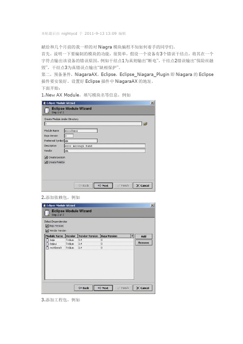
本帖最后由nightycd 于2011-9-13 13:09 编辑献给和几个月前的我一样的对Niagra模块编程不知如何着手的同学们。
首先,说明一下要编制的模块的功能,很简单,假设一个设备有3个错误干结点,将其在一个字符点输出该设备的错误原因,例如干结点1为真则输出“断电”,干结点2错误输出“保险丝融毁”,干结点3为真错误点输出“缺相保护”。
第二,预备条件,NiagaraAX,Eclipse,Eclipse_Niagara_Plugin即Niagara的Eclipse 插件要安装好。
设置好Eclipse插件中NiagaraAX的地址。
下面开始:1.New AX Module,填写模块名等信息,例如2.添加依赖包,例如3.添加工程包,例如4.完成向导。
5.右键单机刚建立工程里com.sh.eb包,选new->new class,填写类名并设定依赖包,例如此步要注意的是,类名首字母必须是大写B,第二个字母必须大写,否则Niagara插件的Slotomatic工具可能不过滤你的类文件。
建立好类后,应显示类,并自动添加形如以“/*”- 开头“-*/”结尾结尾的Slotomatic 注释区域,该区域用起来很方便。
6.使用Niagara插件的Slotomatic工具,过滤你的文件,如条件符合,你会发现类文件中多了类型返回语句,点击Ctrl+shift+o,添加javax.baja.sys.TYPE类型的import。
还有,module-include.xml文件中添加了如下语句<type name="ErroBand" class="com.sh.eb.BErroBand"/>7.添加输入属性和输出属性,将例子中BErroBand类中的Slotomatic注释区域编辑为如下语句/*-class BYcBoolBandString{properties{InBool_1:BStatusBooleandefault{[ new BStatusBoolean(false) ]}flags{ summary,executeOnChange }InBool_2:BStatusBooleandefault{[ new BStatusBoolean(false) ]}flags{ summary,executeOnChange }InBool_3:BStatusBooleandefault{[ new BStatusBoolean(false) ]}flags{ summary,executeOnChange }InBool_1_BindingString:BStatusStringdefault{[ new BStatusString("Bool_1 band Message") ]} flags{ summary }InBool_2_BindingString:BStatusStringdefault{[ new BStatusString("Bool_2 band Message") ]} flags{ summary }InBool_3_BindingString:BStatusStringdefault{[ new BStatusString("Bool_2 band Message") ]} flags{ summary }OutMessage : BStatusStringdefault{[new BStatusString("")]}flags{summary}}actions{}topics{}}-*/其中InBool_1、2、3为输入的3个设备故障干结点,有任何变化都会触发事件。
niagara中间件软件安装及测试文档

6测试硬件测试用万用表测试左右扇面的24V+与24VG是否短路用万用表测试左右扇面的5V与5VG是否短路电源没有短路即可上电,若有短路,排查短路原因。
软件测试6.2.1软件安装1、将U盘中的文件拷贝到一体机D盘下。
2、安装IndyTool v2.3.0,找到D:\一体机软件\R2000\IndyTool中的图标,双击进行安装。
3、将D:\一体机软件\F860光盘文件\app中的,,,建立桌面快捷方式。
4、安装Niagara,运行Niagara在D盘下建立文件夹作为安装Niagara路径解压到’Niagara相关’文件夹下,参考文档。
在D: \一体机软件\Niagara 相关\Niagara_AX_Developer-中,双击图标,开始安装点击下一步,选yes,点下一步路径选择为D:\Niagara\Niagara-,点下一步:选择select All选下一步:点下一步:点完成,用注册码激活软件将D:\一体机软件目录下的modules文件夹粘贴到D:\niagara\Niagara-目录下的modules中;将D:\一体机软件目录下的demo文件夹覆盖D:\niagara\Niagara-\stations目录下的demo文件。
Niagara软件安装完毕。
5、安装Java JDK:找到D:\一体机软件\下的双击进行安装。
6、将D:\一体机软件\搜索配置设备创建到桌面。
6.2.2软件配置6.2.2.1路由器配置步骤:1、用一条网线将路由器的一个LAN口与电脑的网口连接。
2、打开电脑上的浏览器,输入后,得到如下页面:查看路由器上的用户名和密码(注意,该用户名和密码为出厂初始密码,在路由器背面有标注)输入到上图中。
例如:使用TP-LINK路由器,初始用户名为admin,密码为admin。
输入用户名和密码确定后得到如下页面:3、在上面页面中选择“无线管理->无线基本设置”,来设置路由的SSID号。
设置完后,点击“保存”,设置如下图所示:4、在上面页面中选择“无线管理->无线安全管理”,设置安全模式为WEP,密钥长度为64bits,密钥格式为ASCII,然后设置密钥,例如“abcde”(此处仅举例,密钥可根据情况自行设置)(同一实训台M4网关SSID,密钥,要设置成一样的,设置方法见下文),设置完后,点击“保存”,设置如下图所示:5、选择“DHCP服务器”,设置DHCP服务器状态为“开启”“保存生效”,完成设置。
aqua barista 使用说明书
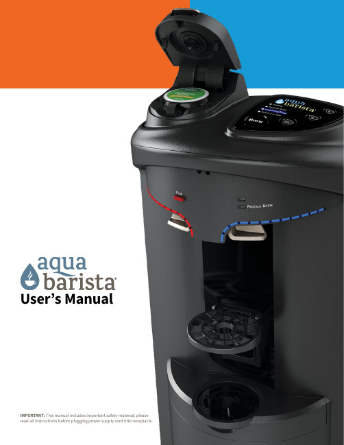
User’s Manual IMPORTANT: This manual includes important safety material; pleaseRead complete HOW TO INSTALL instruction sequence before plugging in and turning on dispenser. Failure to follow proper installation instructions may cause damage to water dispenser.STOP & READ DIRECTIONSbefore plugging in dispenser.SAFETY PRECAUTIONSBasic safety precautions should be followed when using electrical appliances, including: • Only plug in dispenser in the sequence the manual indicates (see HOW TO INSTALL AND USE).• In accordance with these instructions, the dispenser must be properly located and installed before use (see HOW TO INSTALL AND USE).• Use only bottled water in the dispenser.• Do not use with water that is microbiologically unsafe or of unknown quality.• Keep all flammable liquids or vapors away from all appliances.• Dispenser must be unplugged before cleaning, sanitizing or repairing (see CLEANING AND SANITIZING).• Wipe up any water spills immediately after loading or unloading water bottles.• The dispenser heats water to a temperature above 196º F (91.5º C). Water temperatures above 125º F (52º C) can cause severe burns or death from scalding. Most at risk of being scalded are children, the disabled and the elderly.• Ensure the dispenser stands upright for 2 hours before loading water bottle, plugging in and turning unit on.• Always lift dispenser by handle located on rear of unit. Lifting dispenser by faucet or faucet levers will damage the unit.• Follow proper grounding safety precautions and instructions prior to plugging in the unit (see GROUNDING SAFETY PRECAUTIONS AND INSTRUCTIONS).• Do not use an extension cord.• Supervise children when using the dispenser (see CHILD SAFETY).WARNING: Do not remove drain plug from the hot tank.GROUNDING SAFETY PRECAUTIONS AND INSTRUCTIONSWARNING: The dispenser must be grounded – if the appliance is improperly grounded, the result could be electric shock. Do not immerse cord, plug or any other part of the dispenser in water or other liquids.Ensure that the available power supply matches the dispenser’s voltage specifications indicated on the nameplate label (located at the rear). Please ensure that dispenser is set up so access to the power outlet and plug is unobstructed.IMPORTANT : To provide additional protection from the risk of shock, the dispenser MUST be connected to a ground fault circuit interrupter (GFCI) outlet at all times. Use of an extension cord will void any warranties.If the supply cord is damaged, it must be replaced by a special cord or assembly available from the manufacturer or its service agent.Always grasp plug and pull straight out from outlet. Never unplug by pulling on power cord.Load water bottle FIRST.turn on the hot tank switch.water from hot and cold faucets.CHILD SAFETYCAUTION:Supervise children when using the dispenser.The hot dispenser faucet is equipped with a child safeguard that reduces the risk of hot water being dispensed accidentallyor by small children. To dispense hot water, simultaneously depress the child safety lock (located above the left hot faucet lever) and the left hot faucet lever. Do not allow children to hang, climb or stand on the dispenser; the dispenser could fall over and the child could be injured.RECEIVINGInspect the dispenser box carefully for any evidence of shipping or handling damage before signing to receive goods.In case of shipping damage, claims should be filed immediately with the carrier.HOW TO INSTALL AND USEWARNING:Read through every step in HOW TO INSTALL AND USE before plugging in or turning unit on. Do not turn on the hot tank switch until completing step #15. Failure to follow the installation steps in order could causea hot tank failure.1. Install dispenser on a level floor strong enough to support it when fully loaded.2. Ensure dispenser stands upright for a minimum of 2 hours before loading water bottle, plugging in and turning on dispenser.3. Place dispenser a minimum of 4 inches away from the wall to ensure ventilation.4. Do not install dispenser where it will be subject to direct sunlight, heat or moisture.5. Do not install dispenser where the temperature will go below 50º F (10º C) or above 100º F (38º C).6.7.8. Place fresh bottle outside of the cabinet.9.10. Unpackage the bottle adaptor from the bag inside the cabinet. Remove the protective red cap from the SmartFlo™ WaterSystem hose. Insert the hose into the bottle adaptor cap.NOTE: Touching the bottle adaptor assembly pieces with bare hands could cause contamination. Be sure11. Place the bottle adaptor probe into the bottle.NOTE:REPLACING BOTTLE1. Open cabinet door.2. Place new bottle outside of cabinet.3. Remove empty bottle from cabinet.4. Remove bottle cap sticker completely from the top of the bottle.5. Remove the bottle adaptor assembly from the empty bottle and place the bottle adaptor assembly into the new bottle.NOTE: Do NOT touch the bottle adaptor tubing. Remove the bottle adaptor assembly and install the bottle adaptor assembly by grabbing the cap only. Place the bottle adaptor into the new bottle immediately to avoid contaminating the bottle adaptor tube.14. Install drip tray.1 minute (or until water begins to flow from the faucet) and then depressing the hot water lever for approximately 1 minute (or until water begins to flow from the faucet).17. NOTE:BREWING INSTRUCTIONSWARNING:Always use caution when handling hot water.4.1. 2.K-Cup® pod into holder(Fig 2).3.until locked(Fig 3).5.and coffee will brew. If dispense light is not lit, water has notreached optimum brewingtemperature. Wait for the lightindicator to turn solid, and thenpress button to brew(Fig 5).6. Once the brew cycle is complete,open handle to remove browncoffee pod holder. Discard empty K-Cup® pod but do not discardthe coffee pod holder. Place thebrown coffee pod holder back inplace for the next user (Fig 6).CLEANING AND SANITIZINGLoad waterbottle FIRST.turn on the hot tank switch.water from hot and cold faucets.WARNING:Dispense water through the hot and cold spigots before turning on the hot tank switch. Failure to follow proper installation instructions may cause damage to water dispenser.TIP:18. 19. 20. 22. 23. 24. water flows continuously. door top right.TROUBLESHOOTINGWARNING: Always turn off dispenser and unplug from power outlet before inspectingor starting any maintenance.WATER IS LEAKING• Bottle may have a leak. Remove and install new bottle.• If water is present only at base of unit (not dripping from above), first try to replace the water bottle.• If water is leaking from above the bottle (or not bottle related), unplug dispenser and remove bottle. Check water connections and hose connections for holes, cracks or cuts.WATER DOES NOT FLOW FROM DISPENSER• Make sure bottle is not empty; if empty, replace bottle.• Ensure that water selection lever is fully depressed.• Inspect to see if there is a pinhole in the bottle; if so, replace bottle.• Ensure hot/cold tanks have been primed (see priming of water system in HOW TO INSTALL AND USE).• Ensure all SmartFlo™ tubing is free of any holes, cuts or cracks.• Ensure SmartFlo™ locking knobs (in top) are securely locked in place.• Ensure unit is plugged in.• Make sure the tubing lock clip is securely snapped in place.WATER NOT HOT OR COLD ENOUGH• Check to make sure dispenser is plugged in and the hot tank heater switch is turned on.• A fuse may be blown or the circuit breaker may be tripped; if needed, replace fuse or reset breaker.• Dispenser may be placed in direct sunlight or may be too close to a heat source. Try moving dispenser into a cool, shaded area.• Ensure hot/cold tanks have been primed (see priming of water system in HOW TO INSTALL AND USE).• Ensure SmartFlo™ locking knobs (in top) are securely locked in place.BREWED BEVERAGE OVERFLOWS INSIDE UNITNote: Run water through the AquaBarista by completing a couple of brew cycles without a K-Cup® pod to ensure that the coffee pod holder is clean. If the unit continues to overflow outside the unit proceed to the next step.· Brewer mechanism may be clogged. Remove coffee pod holder assembly and rinse thoroughly or wash in top rack of dishwasher.· Always remove K-Cup® pods from unit after brewing. K-Cup® pods left in unit for extended periods can cause clogs.Note: If overflow occurred in the morning, recheck the AquaBarsta in the afternoon. If overflow occurred in the afternoon, recheck the AquaBarista in the morning. This will allow time for the printed circuit board to dry.BREWER NOT WORKING· Ensure only Keurig brand K-Cup® pods are used. Subtle design differences in other pods can impede or prevent brewing.· Remove K-Cup® pod from unit and check bottom of pod for puncture. If it is not punctured, return it to unit and press it firmly down into the coffee pod holder assembly to ensure complete contact with the unit’s bottom needle.DISPENSER NEEDS TO BE STORED• Always drain water completely from dispenser before shipping or storing.NOTE: Water left in the dispenser can freeze, damaging the dispenser.IMPORTANT: The customer acknowledges that water, like other liquids, can cause damage to surfaces. Thecustomer takes full responsibility for placing the dispenser within a residence or business and acknowledgesthat failure to address drips, leaks or spillages is at the customer’s risk.WARNING: The Limited 1-Year Warranty and Underwriters’ Laboratory and CE listings for the dispensers areinvalidated if any alterations, modifications, or use or misuse in combination with any other machines or devices isdeemed to be the source of any claim. See warranty document for complete terms and conditions. Primo Water NorthAmerica accepts no liability (including for bodily injury) resulting from any alterations, misuse, neglect, accidents,improper installations or repairs. The appliance is not intended for use by persons (including children) with reducedphysical, sensory or mental capabilities, or lack of experience and knowledge, without supervision by a personresponsible for their safety.The AquaBarista® is programmed for use of Keurig K-Cup® branded products only. U se of pods other than Keurig K-Cup® branded products may impede optimal performance of the brewer. 11K-Cup® is a registered trademark of Keurig Dr Pepper, Inc.©2023 DS Services of America, Inc., dba Primo Water North America。
Niagara技术文档汇总
Niagara技术文档汇总Niagara技术文档汇总一、多Station间访问一次验证登陆本节主要解决一个比较庞大的系统中有多个站点需要管理时,通过浏览器跨Station 直接登陆而不需要重新输入用户名和密码的问题,这个功能不是新开发或者特地编写程序实现,而是Niagara平台自带的功能。
这个功能对于解决IBMS和连锁行业具有多个站点的项目非常有用。
因为Niagara 平台默认情况下,跨Station之间登陆是需要重新验证用户名和密码,关于这方面的知识原文请参考NiagaraAX的帮助文档:Doc_User\NiagaraAX User Guide\About Security\Security model overview\Multi-station security notes里的说明(强烈建议先对原文浏览一遍),这里只用简要的文字说明其中的配置要点,供大家参考。
1.1关键配置◆不同的Station需要有相同的用户名和密码,在AX-3.3以上的版本可以通过Network User(请参考关于Network User说明的相关配置文档)实现在不同的Station间自动同步用户名和密码,而用户导航、Profile等属性可以自定义;◆Station之间的访问必须通过域名而不能通过IP地址进行访问;如果有固定的域名则可直接配置域名访问,如果是本地的局域网,则可通过Niagara提供的虚拟域名进行访问;◆在一个Station里的PX(或者文本链接,或图片链接)连接到另一个Station的Hyperlink格式也必须使用域名而不能使用IP地址;◆必须对访问Station的客户端电脑配置Hosts文件。
1.2示例说明假设在一个局域网里有两个Station,本例中没有固定的域名,因此需要用到Niagara 提供的虚拟域名(不确定是Niagara提出的还是Windows本来就有,我是初次在Niagara 文档中接触这个概念)Station名字为Sample1(ip:192.168.1.100)和Sample2(ip:192.168.1.200)。
Niagara历史记录介绍

5.2 添加历史记录Extension到组件
• Extension类型
– BooleanChangeOfValue – BooleanInterval – NumericChangeOfValue – NumericInterval – EnumChangeOfValue – EnumInterval – StringChangeOfValue – StringInterval
2.3 log history service
• Station的标准输出可以看见的信息的缓存 历史记录。 • 用途
– Station的故障处理(troubleshooting)。
• 部分属性
– Enabled – Minimum Severity 设置记录的最小输出级别:Error、Warning、 Trace、Message。
– 关闭所有在Max Open Time内没有被访问的历 史记录。
2.2 audit history service
• 保存用户做的改变的历史记录。 • 记录一个组件上的所有属性的改变、活动 发生等,如下:
– Property changed – Property added – Property removed – Property renamed – Properties reordered – Action invoked
5.3 配置历史记录Extension
– Status, Fault Cause, Enabled – Active Period – Active, History Name – History Config Id, Source, Time Zone, Record Type, Capacity, Full Policy, Interval, System Tags, valueFacets. – Change Tolerance – Interval – minRolloverValue, maxRolloverValue – precision
- 1、下载文档前请自行甄别文档内容的完整性,平台不提供额外的编辑、内容补充、找答案等附加服务。
- 2、"仅部分预览"的文档,不可在线预览部分如存在完整性等问题,可反馈申请退款(可完整预览的文档不适用该条件!)。
- 3、如文档侵犯您的权益,请联系客服反馈,我们会尽快为您处理(人工客服工作时间:9:00-18:30)。
中间件Niagara的使用说明
一、启动Workbench
1.启动后台服务
2.启动控制台
3.打开控制台后,输入WB 启动workbench
二、打开workbench
1.打开plantform
输入电脑的用户名和密码(本机或者要访问的电脑),点击OK
双击Application Director,打开应用向导
显示station列表
选择demo,点击start,启动,会看到demo状态变化“Idle→Starting→Running”
说明:每台电脑可以同时启动多个station,前提是它们所使用的端口不能相同。
2.打开已有的Station
相应的Station就被启动,图标显现颜色。
界面中最重要的几个部分导航栏,调色板和主面板
说明:导航栏是树形的结构,可以通过双击的方法来选择要浏览的界面调色板用来选择不同的组件
主面板是显示station内容的地方
在导航栏或者主面板,都可以通过双击来打开想要浏览的页面二、新建Station
点击Tools-New Station
输入该站点的名称,点击Next
输入用户名、密码、端口号,点击Finish,即完成
建好之后,在platform下的Application director-station上右键,可以启动该station。
station启动后,可以通过file-open-open station来打开正在运行的station。
这样,你就会在platform下面的节点处看到这个station了。
说明:station其实是在后台运行的,前面所看到的一切,都是通过workbench远程连接而展示出来形象化界面。
所以,workbench关掉了,不会影响到后台station的运行。
除非通过application director发送命令将该station停止。
三、建立数据采集
1.新建文件夹
在导航栏config上右键,New Folder新建文件夹,输入名称,点击ok
在导航栏就会显示新建的文件夹
2.新建view
在选定的文件夹图标上点击右键,views new view 输入相应的名称,点击ok
出现图形视图的编辑界面
3.新建数据点
有四种数据类型:布尔型,数字型,枚举型,字符串型。
方法一:右键点击Folder→New→选择需要的数据点类型,输入名称,点击ok
方法二:在WireSheet 中,右键New 选择需要的数据点类型,输入名称,点击ok
4.建立逻辑关系
把点和图形组件绑定到一起有两种方法:
方法一:直接把点从导航栏拖拽到主面板中,然后为其选择一个图形组件。
说明:在这个界面下面有几种选择:
Bound Label 是直接把内容显示在界面上。
From Palette 是从调色板中选择图形组件来显示。
选择From Palete
点击打开图标有多个图形组件库可以选择,例如kitPx,kitPxHvac,kitControl,bajaui等。
输入需要的控件库名称
调色板中就会出现选定控件库内的所有控件列表,选中需要的空间,点击ok
显示所选控件图标
点击图标Toggle View/ Edit View 可以在预览模式和编辑模式下切换。
可以通过set方法,设置点的值。
或者
点击ok
在图形界面中可以看到控件随着数值的变化而变化
方法二:先把图形组件添加到界面上,然后再绑定点。
先在调色板中选定相应的组件,点击打开图标,输入控件库名称,点击ok
选择需要的组件图标,直接拖拽到主面板中
编辑模式下就会出现选定的组件图标
绑定:双击图形,或者右键,选择Edit Properties。
找到绑定值,点击浏览,选择逻辑点
点击ok ,在属性列表中就会显示绑定信息,点击ok ,即绑定完成
可以通过set方法,设置点的值。
来验证绑定是否成功。
此处设置值为60 ,初始值0,看到变化即验证。
四、建立逻辑关系
用到表示逻辑的组件
提示:温度值为NumericWritable,报警灯的数据类型为BooleanWritable,
要用到的组件可以在KitControl 模块下面的Logic 以及Constants ,Util 文件夹里面找。
1.将一个数字型常量拖拽到wire sheet 连线视图下,输入名称,点击ok
通过set,将常量的值修改为30.
选择logic下的GreaterThan大于比较组件,拖拽到wire sheet 连线视图下,输入名称,点击
ok
连线:输出对应输入
看结果:在px视图下可以开到灯的变化。
数值为60时,灯亮。
数值为25时,灯灭。
五、网页访问
1.新建文件夹,右键点击files→new→new folder,输入名称nav,点击ok
2.新建导航文件,右键点击文件夹nav→new→NavFile.nav,输入文件名称,点击ok
在导航栏中可以看到新建的文件夹和文件
双击userservice admin
选择导航文件
双击NavFile.nav home
设置完成。
4.用浏览器访问http://localhost
可以在网页中,通过右键set,来修改组件的值。
六、显示历史数据/记录一段时间内的数据
1.选择模拟信号源
先从调色板中选择sinwave正弦波发生器,拖拽到wire sheet 连线视图下,输入名称,点击
ok
2.新建一个数字型变量,命名data
3.创建历史记录属性
双击data,显示属性。
在调色板中history→Extensions→NumericInterval,这是创建数据的历
史记录使用的组件,表示按间隔记录数据点。
将此空间拖拽到data属性列表中,命名。
4.设置属性
打开NumericInterval属性前面的+号,将Enable是能端改为true;Interval设置采点间隔。
将信号发生器的out与data的in连线
5.图形视图显示
双击Folder,显示图形视图,点击编辑模式,把导航栏中的data的属性NumericInterval拖
拽到视图中。
选择Workbench View History Chart历史记录曲线图
此时,数据曲线就显示在图形界面中了。
用浏览器访问http://localhost/
1.打开plantform:【File】->【Open】->【Open Platform】
输入电脑的用户名和密码(本机或者要访问的电脑的用户名及密码),点击OK
1、新建Station:【Tools】->【New Station】
输入要创建的Station名:SmartHome->【Next】->输入Station的访问密码(默认Station的用户名为:admin,密码可以为空)->【Finish】完成。