QSC24ENANO可编程控制舵机板使用说明要点
树莓派舵机扩展板 Servo Driver HAT 用户手册

Servo Driver HAT用户手册前言本产品是基于树莓派而设计的PWM/舵机扩展板,通过PCA9685芯片扩展16路舵机控制或者PWM输出,每个通道12位分辨率。
通过I2C接口控制,无需占用额外的引脚。
板载5V稳压芯片,可接电池供电,最大输出3A电流。
适用于控制机械手臂,以及各种舵机机器人。
产品特性输入电压VIN:6V~12V舵机电压:5V逻辑电压:3.3V驱动芯片:PCA9685控制接口:I2C产品尺寸:65mm x 30mm固定孔通径:3.0mm硬件说明板子可以从树莓派上取电不需要额外供电。
也可以通过右边绿色端子VIN接电池供电,输入电压范围6V~12V。
经过板载的5V稳压芯片输出5V电源给舵机和树莓派供电,最大输出电流3A。
A0~A4可以设置PCA9685芯片的I2C设备地址,可以同时接多个Servo Driver HAT最上面的排针是舵机接口,黑色排针是GND(大部分舵机对应的是褐色线), 红色排针是5V电源,黄色排针是PWM信号线,有0~15个通道,可以同时接16个舵机。
注意舵机线不要接反,否则舵机不会转动。
注意:如果接大功率的舵机可能会出现供电不足的现象,需要接更多的电源使用指南开启I2C接口执行如下命令进行树莓派配置:sudo raspi-config选择Interfacing Options -> I2C ->yes 启动i2C内核驱动注意:运行程序后有提示I2C错误,可以运行如下命令打开配置文件sudo nano /etc/modules如果没有这两行语句则添加上去,并保存退出。
i2c-devi2c-bcm2708运行程序我们提供python2和python3的示例程序,功能包括简单的PCA9685库测试程序,wifi遥控程序以及蓝牙遥控程序。
其中wifi和蓝牙遥控发送端是通过手机APP发送指令,需要安装对应的APP(只支持安卓) 手机下载相应的APP并安装。
QSC24E(NANO)可编程控制舵机板使用说明

舵机板上位机软件使用说明参考QSC32E使用说明这里详解ARDUINO-NANO配合舵机板QSC24E-NANO来解码PS2并使用手柄按键的功能,以及ARDUINO对舵机板接口通讯说明。
此功能仅QSC24E-NANO可用此舵机板套件分别为3块PCB组成,最左边为24路带过载保护的舵机控制板,(专门处理多路舵机控制)。
中间为ARDUINO-NANO编程控制板,PRO-MINI 为编程控制主板(专门负责处理数据编程)使用,最右边为的串口调试板(可给舵机板调试也可给ARDUINO-NANO下载程序)。
此舵机板,他上面可直接插PS2手柄的接收器,其解码是通过ARDUINO-NANO 来完成的。
L1:舵机供电电源指示灯L2:通讯指示灯,随着主板接收外部信号L2跟着同步闪动L3:舵机板状态显示灯。
此舵机板带有电压检测功能,当VSS主板电压低于6.8V (默认为7.4V锂电池供电),或者舵机(+-)电压低于5.5V(默认为7.4V锂电池接入1.3V降压二极管),此时L3灭掉,并伴随喇叭报警。
提示电池电压不足用户需要给电池充电1.驱动的安装:插上CP2102串口设备的USB线,并安装驱动,驱动为ARDUINO-QSC24E(CP2102)驱动对应不同的操作系统选择不同的驱动文件安装,这里注意,如果驱动没有安装时候CP2102串口设备的红色指示灯不会亮,只有正确安装好驱动后,CP2102串口板上的红色指示灯才点亮。
CP2102串口设备使用6P线连接下面的舵机板,连线为BLK---BLK,GRN---GRN.即通过上位机软件Q-robot_Servo_Control调试机器人舵机CP2102串口设备使用6P线连接上面的ARDUINO编程板,连线为BLK---BLK,GRN---GRN.即通过编程软件软件arduino下载机器人主程序。
2.主板的供电VSS表示主板供电正极电压,供电电压为6.5V-12V。
默认为7.4V+表示舵机供电正极电压,供电电压为5.5V-8V。
黄石科威24V新型EC、EP说明书
AI6+、AI6-:6#通道模拟量输入端子,接热电偶、标准信号、PT100 信号。 AI7+、AI7-:7#通道模拟量输入端子,接热电偶、标准信号、PT100 信号。 AI8+、AI8-:8#通道模拟量输入端子,接热电偶、标准信号、PT100 信号。 AI9+、AI9-:9#通道模拟量输入端子,接热电偶、标准信号、PT100 信号。 CANH、CANL:CAN 网络接口端子。 A、B : RS485 网络端子 A+、B-,固化 CAN 网络配置、组建 RS485 网络。固化 CAN 网络配置时要另配 485/232 转换器。 RS0:编程口,为 232 接口,配专用通讯电缆,下载程序、与人机界面连接。 拨码开关:运行控制端子,拨动拨码开关,可编程控制器处于 RUN 或 STOP 状态。
壁挂式垂直安装
4
★ 接地方式 专用接地(最好) 共用接地(可) 公共接地(不可)
1.2 外形结构尺寸
产品型号
L(mm) 产品型号
L(mm)
EC/P-08M08R-24 100
EP-10H-24
100
EC/P-08M08T-24 100
EP-32M-24
140
EP-10E-24
100
EP-32T-24
使用注意事项
● 可编程控制器的安装位置尽量远离高电压、强电流、高频率等对周围有较强干扰的设备。 ● 请一定在可编程控制器外部组成紧急停电电路,制止正反动作同时进行的连锁电路、上下限定位连锁电路。 ● EC/EP 系列可编程控制器指令集有 86 条指令,如果程序中含有超出这 86 条指令范围的指令,可编程控制器运行时会出错。 ● 在下载梯形图或固化 CANSET 时,下载完毕后,将拨码开关拨到 RUN,等可编程控制器运行后,才能断电,否则,程序得不到固化。 ● 对于变更运行中的程序、强制输出、RUN、STOP 等操作,必须熟读使用手册,充分确认其安全之后进行。
QSC24E(NANO)可编程控制舵机板使用说明要点

舵机板上位机软件使用说明参考QSC32E使用说明这里详解ARDUINO-NANO配合舵机板QSC24E-NANO来解码PS2并使用手柄按键的功能,以及ARDUINO对舵机板接口通讯说明。
此功能仅QSC24E-NANO可用此舵机板套件分别为3块PCB组成,最左边为24路带过载保护的舵机控制板,(专门处理多路舵机控制)。
中间为ARDUINO-NANO编程控制板,PRO-MINI 为编程控制主板(专门负责处理数据编程)使用,最右边为的串口调试板(可给舵机板调试也可给ARDUINO-NANO下载程序)。
此舵机板,他上面可直接插PS2手柄的接收器,其解码是通过ARDUINO-NANO 来完成的。
L1:舵机供电电源指示灯L2:通讯指示灯,随着主板接收外部信号L2跟着同步闪动L3:舵机板状态显示灯。
此舵机板带有电压检测功能,当VSS主板电压低于6.8V (默认为7.4V锂电池供电),或者舵机(+-)电压低于5.5V(默认为7.4V锂电池接入1.3V降压二极管),此时L3灭掉,并伴随喇叭报警。
提示电池电压不足用户需要给电池充电1.驱动的安装:插上CP2102串口设备的USB线,并安装驱动,驱动为ARDUINO-QSC24E(CP2102)驱动对应不同的操作系统选择不同的驱动文件安装,这里注意,如果驱动没有安装时候CP2102串口设备的红色指示灯不会亮,只有正确安装好驱动后,CP2102串口板上的红色指示灯才点亮。
机软件Q-robot_Servo_Control调试机器人舵机即通过编程软件软件arduino下载机器人主程序。
2.主板的供电VSS表示主板供电正极电压,供电电压为6.5V-12V。
默认为7.4V+表示舵机供电正极电压,供电电压为5.5V-8V。
默认为7.4-1.3V(即7.4V锂电池接一次降压快)注意以上如果不是默认电压。
主板的低压报警喇叭在电池电压过低的时候不会发生报警。
默认的供电连线如图所示。
3.PS2手柄连线、外接拨动开关的连线。
舵机控制板使用说明
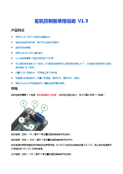
舵机控制板使用说明V1.3产品特点●采用32位ARM 内核的处理器芯片●独创的在线升级机制,用户可以在线升级固件●自动识别波特率●采用USB和UART通讯接口●1us的控制精度(相当于舵机的0.09度)●可以同时同步控制32个舵机(24路舵机控制板可以同时同步控制24个,16路舵机控制板可以同时同步控制16个舵机)●内置512K 存储芯片,可存储上百个动作组●功能强大的电脑软件(内置3种语言,简体中文、繁体中文、英语)●拥有Android手机控制软件(需配合蓝牙模块使用)供电舵机控制板需要2个电源: 舵机电源和芯片电源(舵机的功率比较大,所以不建议共用一个电源)舵机电源(正极):VS(图中3号位置的蓝色接线端子的右端)舵机电源(负极):GND(图中3号位置的蓝色接线端子的中间)舵机电源的参数根据实际所接舵机的参数而定,如TR213舵机的供电电压是4.8-7.2V,那么舵机电源就可以用电压在4.8-7.2V之间的电源。
芯片电源(正极):VSS(图中3号位置的蓝色接线端子的左端)芯片电源(负极):GND(图中3号位置的蓝色接线端子的中间)VSS的要求是6.5-12V,如果芯片供电是从VSS端口输入的,那么电源的电压必须是6.5-12V之间。
另外:1. 图中2号位置的USB接口可以给芯片供电,所以USB接口和VSS端口,任选其一即可。
2. 图中1号位置也可以给芯片供电,标记为5V和GND,5V是正极,GND是负极,供电电源的电压必须是5V。
3. 1234. 图中4号位置的绿色LED灯是芯片电源正常的指示灯,绿色灯亮,表示芯片供电正常,绿色灯灭,表示芯片供电异常。
5. 图中5号位置的绿色LED灯是舵机电源正常的指示灯,绿色灯亮,表示舵机供电正常,绿色灯灭,表示舵机供电异常。
2安装驱动驱动下载地址:/down/usc_driver.exe (全部是小写)直接双击usc_driver.exe ,点击下一步即可安装驱动。
四轴可编程控制器说明书(含圆弧直线实现方式)

四轴可编程控制器说明书(含圆弧直线实现方式)珩源电子科技 一、 功能与接线描述1、可控制xy两轴电机配合走直线插补和圆弧插补;2、可控制4路步进电机同时工作,工作频率每路100KHZ(最高达150KHZ):特别注意的是对应盒子上的标注,DR1为X轴的方向控制脚,DR2为Y轴的方向控制脚,DR3为Z轴的方向控制脚,DR4为C轴的方向控制脚; CP1为X轴的脉冲控制脚,CP2为Y轴的脉冲控制脚,CP3为Z轴的脉冲控制脚,CP4为C 轴的信号控制脚。
与驱动器接的时候,以X轴为例,把驱动器公开端(控制盒子上标注的5V输出脚)接你方驱动器的CP+\DR+;用控制器的CP1接控制器的CP-,用控制器的DR1接你方驱动器的DR-。
这种接法叫单端接法。
如下图一所示。
3、5路继电器输出(常开触点、内部加了RC去弧电路),7路OC输出(控制外部24V继电器或电磁阀)特别注意:对应文本上设定Y1-7表示控制7路OC;Y8-12对应本控制器的5路继电器输出。
如下图一所示。
4、13路光耦隔离输入(每路外部接到地表示接通):盒子上标为YL1-YL13,分别对应输入X1-X13(在文本上设定):特别说明的是对应外部的输入信号,平时悬空或为24V(控制器工作的输入电源24V),当外部输入信号为电源24V的地的时候表示这个输入口有效。
经常外接开关按钮,或光电反馈开关,接触开关反馈信号等。
如下图一所示。
5、通过串口与外部文本进行通信功能6、可存储10个工程,每个工程可以设置50步二、编程界面和说明1、运行主界面X\Y\Z\C 四轴的运行参数进行实时显示,单位是MM。
参数对应按键,进入相应的设定界面。
测试对应按键,进入相应的测试界面。
启动对应按键,对应启动当前的工程进行运行。
停止对应按键,将停止当前运行的工程,不管当前运行工程到哪一步。
当“启动”时将重新按工程的第一步开始运行。
量产是对应工程的运行次数,假定工程运行一次,加 1.可以按“SET”键进行设定数字,比如清“0”。
机械手舵机的用法及程序

舵机是一种位置伺服的驱动器,主要是由外壳、电路板、无核心马达、齿轮与位置检测器所构成。
其工作原理是由接收机或者单片机发出信号给舵机,其内部有一个基准电路,产生周期为20ms,宽度为1.5ms的基准信号,将获得的直流偏置电压与电位器的电压比较,获得电压差输出。
经由电路板上的IC 判断转动方向,再驱动无核心马达开始转动,透过减速齿轮将动力传至摆臂,同时由位置检测器送回信号,判断是否已经到达定位。
适用于那些需要角度不断变化并可以保持的控制系统。
当电机转速一定时,通过级联减速齿轮带动电位器旋转,使得电压差为0,电机停止转动。
一般舵机旋转的角度范围是0°到180°度。
舵机有很多规格,但所有的舵机都有外接三根线,分别用棕、红、橙三种颜色进行区分,由于舵机品牌不同,颜色也会有所差异,棕色为接地线,红色为电源正极线,橙色为信号线。
舵机的转动的角度是通过调节PWM(脉冲宽度调制)信号的占空比来实现的,标准PWM(脉冲宽度调制)信号的周期固定为20ms(50Hz),理论上脉宽分布应在1ms到2ms之间,但是,事实上脉宽可由0.5ms到2.5ms之间,脉宽和舵机的转角0°~180°相对应。
有一点值得注意的地方,由于舵机牌子不同,对于同一信号,不同牌子的舵机旋转的角度也会有所不同。
大概了解了舵机以后,我们就试着来控制一个舵机吧,将GND和+5V连接好之后,我选择信号输入口为数字接口7,至于供电部分要注意,舵机转动时电流会比较大,连接好电路就来编写程序吧,我就让舵机转动到我输入数字所对应的角度数,并将角度显示到屏幕上。
程序如下:int servopin=7;//定义舵机接口数字接口7int myangle;//定义角度变量int pulsewidth;//定义脉宽变量int val;void servopulse(int servopin,int myangle)//定义一个脉冲函数{pulsewidth=(myangle*11)+500;//将角度转化为500-2480的脉宽值digitalWrite(servopin,HIGH);//将舵机接口电平至高delayMicroseconds(pulsewidth);//延时脉宽值的微秒数digitalWrite(servopin,LOW);//将舵机接口电平至低delay(20-pulsewidth/1000);}void setup(){pinMode(servopin,OUTPUT);//设定舵机接口为输出接口Serial.begin(9600);//连接到串行端口,波特率为9600Serial.println("servu=o_seral_simple ready" ) ;}void loop()//将0到9的数转化为0到180角度,并让LED闪烁相应数的次数{val=Serial.read();//读取串行端口的值if(val>'0'&&val<='9'){val=val-'0';//将特征量转化为数值变量val=val*(180/9);//将数字转化为角度Serial.print("moving servo to ");Serial.print(val,DEC);Serial.println();for(int i=0;i<=50;i++)//给予舵机足够的时间让它转到指定角度{servopulse(servopin,val);//引用脉冲函数}}}下载完程序就可以输入1到9的数字,让你的舵机转相应的20°到180°了。
飞鸿24路舵机控制器使用说明书

FH24路舵机控制器使用说明书飞鸿科技2012-5-24一、产品介绍 (2)二、接口说明 (3)三、指令说明 (4)1、波特率识别指令 (4)2、舵机移动指令 (5)3、动作组指令 (5)4、脱机运行 (6)四、24路舵机调试软件使用说明 (6)二、连接PC上位机 (8)三、上位机界面编辑 (9)四、单路舵机调试 (11)五、动作组编辑 (11)六、下载调试窗口 (12)五、无线通信 (13)一、蓝牙遥控 (14)1、硬件连接 (14)2、蓝牙设置 (14)二、红外遥控 (18)1、硬件连接 (18)2、应用举例 (18)六、注意事项及故障解决 (19)一、产品介绍1、使用32位ARM芯片,运行速度快,控制精度高。
2、多达24路独立的舵机控制通道,满足大部分用户需求3、512K动作存储,轻松实现脱机运行。
4、1us的位置控制精度,支持命令控制,速度控制(做机器人应选择能进行速度控制的控制器)5、自动识别波特率,方便使用在各种场合。
6、3.8*4.8cm的尺寸。
体积小,重量轻,便于集成到各种人型机器人、仿生机器人、多自由度机械手中。
7、具有联机、脱机、蓝牙无线控制、红外无线控制四种工作模式。
联机模式下,可以通过上位机或单片机进行控制;脱机模式下,自动运行预先通过上位机烧写好的动作,板载512K动作存储器;还可以用蓝牙或者红外遥控器无线控制。
8、控制接口:miniUSB,只需一根usb线即可方便的用电脑给机器人编辑动作,控制机器人运行。
配套的无线通信模块支持蓝牙、红外遥控器控制。
配套的功能强大的PC上位机软件,支持界面编辑,舵机角度编辑,全速/单步调试,动作保存、动作下载、脱机运行设置。
这一切只需动动鼠标,没有任何基础也能搞定。
二、接口说明1、MiNiUSB:可以用来供电,也可以用来通信。
只需用本产品赠送的usb线将控制器与电脑的usb口连接起来就可以控制舵机转动。
2、控制电源接口:给单片机等控制电路供电,如果使用USB供电,此处可不接电源。
舵机控制板使用说明V3torobot

舵机控制板使用说明V3.3规格参数1. 舵机电源和控制板电源分开,独立供电2. 控制通道:同时控制32 路。
(舵机速度可调)3. 通讯输入:USB 或者串口(TTL)4. 信号输出:PWM(精度0.5us)。
5. 舵机驱动分辨率:0.5us , 0.045 度。
6. 波特率范围:9600 19200 38400 57600 115200 128000。
7. 支持的舵机: Futaba 、 Hitec 、辉盛、春天,等市面上 98%以上的舵机8. PCB 尺寸:63.5mm×43.5mm。
9. 安装孔间距:55*35.5mm。
10.存储空间:板载16M U 盘。
1)供电说明本模块电源部分是分离设计的,控制板电源和舵机电源是分开供电的,这样不会相互干扰。
a)控制板电源VSSUSB 接口和蓝色端子中的 VSS 和 GND 都可以给控制板供电,两者任选一种即可。
(VSS 的供电范围是 6.5-12V)b)舵机电源VS舵机的供电情况是根据使用的舵机而定,可以查阅舵机的相关参数,若你不了解,可以使用5V 供电。
VS输入多少付电压,给舵机的就是多少付的电压,所以必须严格匹配舵机的电压参数舵机电源输入接口为蓝色接线端子中的 VS 和 GND。
(控制板电源和舵机电源中的GND 是共用的)常规舵机的电压参数MG995、MG996 供电电压为 4.8-6.8V TR213、TR223、1501MG 供电电压为 4.8-7V TR227 供电电压 4.8-7.2V未知舵机,请给 5V 供电(标准舵机 99%都可以用 5V 供电)如果供电电压超过舵机的范围,有可能造成舵机烧坏,或者烧坏舵机控制板。
请用户谨慎操作,查看舵机的相关参数。
舵机电源的其他说明请看 11 页。
2)安装驱动驱动下载地址:/down/usc_driver.exe (全部小写)直接双击 USC_driver.exe ,点击下一步即可安装驱动。
驱动安装过程中如果出现下面的提示,请选择“始终安装此驱动程序软件”。
舵机控制板使用说明
毛毛雨24路舵机使用说明书
一.毛毛雨24路舵机基本功能
独家特点:采用高速CPU(atme32),处理速度更快,控制更精确,运行更稳定。
你可以不会编程,但是你只要使用你的鼠标,你的机器人就会舞动起来、
完美的脱机运行功能,不要外接单片机,更不要连接PC,即可运行数千个动作指令。
自动识别波特率(9600,19200,38400,57600.1115200,128000)自动识别
真正的舵机运行,按一个开关就可解决问题
USB和TTL串口费用不同的IO口分开处理,绝对没有任何干扰。
产品参数:
1.控制芯片供电范围:4.5V-5.5V(自带稳压芯片,无需多个电源)
2.舵机部分供电范围:DC直流(电压与舵机参数有关,一般使用5-8vDC)
3.信号输出:pwm(精度1us
4.
5.
使用过程:
1、,收到我们的宝贝时,请检查舵机控制板套件是够齐全,包括舵机控制板一块,usb转串口一块,串口线一条。
如果配件不齐全请立刻与我们的客服人员取得联系。
2使用前请先洗手,防静电,舵机控制板在使用时经历,抓住舵孔板的边缘部分,切勿将舵控孔板背面与金属物质接触,防止发生多路烧坏舵机板。
3usb转串口与舵机控制板的连接:用串口线将usb转串口模块与舵机控制板连接起来。
对应的连接为VCC接VCC GND接GND,RXD接RXD TXD接TXD。
(注明;在实际的单片机应用中,一般RXD是接TXD,而TXD是接RXD的。
)
74hc595引脚图管脚图
2008年01月11日 23:59 本站原创作者:本站用户评论(0)
关键字:74(239)
74hc595引脚图
引脚说明。
Mitsubishi MR-C Servo:微型迷你舵机说明书
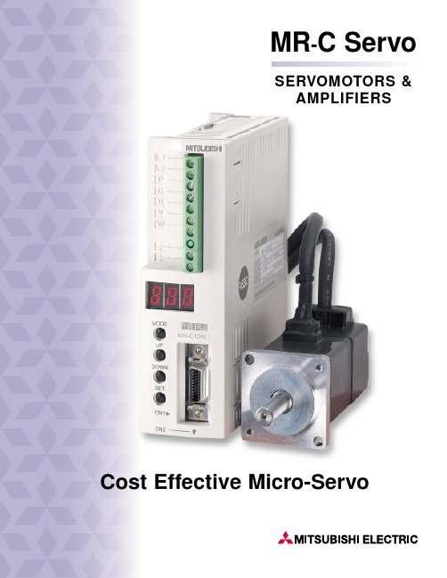
MR-C ServoSERVOMOTORS &LIFIERS Cost Effective Micro-Servo1Actual Size Small,Easy-to-Use,High-Performance.An Extraordinarily Compact,Intelligent Servo.The MELSERVO-C brushless servo,in a handy super-compact size,is the culmination of Mitsubishi servo technology.The servo amplifier achieves high performance in an unprecedented compact body, only 40 millimeters wide and 130 millimeters tall.Small but powerful, it comes equipped with a serial encoder, and is packed with high-level features, including real-time auto-tuning and model adaptive control.This servo can substitute for microstep and five-phase stepping motors, and it can be easily used even by first-time users.A “new age”servo for use in a broad range of fresh applications, including semiconductor manufacturing devices, printing machines and electronic component assembly.2Handy Super-Compact Sizes Servo Amplifier•For up to 400 watts, a super-compact size of only 40 millimeters by 130 millimeters was achieved through the incorporation of a newly developed power module and an optimal thermal design made possible with computer-aided engineering techniques.•Mitsubishi servo control technology including model adaptive control and real-time auto-tuning is achieved with a micro-controller, resulting in the maximum performance with the fewest number of parts.•Select either a single-phase 100 V or 200 V amplifier.s Servomotor•Improved heat dissipation of the motor and a super-compact design were achieved with a molding process that uses newly developedhigh-thermal conductivity resin.(Frame diameter on 100-watt and below units is 40 millimeters square.)•This compact design offers maximum torque of 400% (100-watt and below units) through enhanced coil density made possible through original Mitsubishi technology.•Motors with failsafe electro-magnetic brakes are available.Stepping Motor Replacements No More Cogging or StallingBecause control is performed using integral feedback to verify the servomotor’s position, this unit can start smoothly, without losing step.This is often a problem with stepping motors responding to sudden load fluctuations and sudden acceleration /deceleration.s Smooth OperationOperation is smooth at low speeds and duringacceleration /deceleration because feedback control is performed with a 4,000 pulse /rev encoder.s Stable Torque CharacteristicsReduced machine cycle time and greater production speeds are achieved thanks to stable torque characteristics, from low to high-speeds (maximum rotation speed 4,500 rpm).s Controllable TorquePrevent damage to machines and products by using the torque-limiting feature.Move Up to the Next Level Now010002000300040004500TorqueIntermittent RatingStepping MotorContinuous RatingServomotorRotation Speed (rpm)0-0-Positioning CommandStepping MotorControllerFeedbackServomotorControllerPositioning CommandOpen-Loop ControlStepping MotorSpeed Waveform at 10 rpmServomotorSpeed Waveform at 10 rpmFeedback ControlComparison of Stepping Motor and Servomotor T orque Speed CurvesEasy Operations Real-Time Auto-TuningMerely selecting the response setting that fits themachine being used eliminates the need for servo gain adjustments.This is because the real-time auto-tuning function automatically adjusts the gain to fit themachine.And Mitsubishi’s unique control technology model adaptive control makes possible a highly responsive and stable system.s Automatic Recognition of Motor ModelThe servo amplifier automatically recognizes the drive motor with the motor ID information (motor model name, etc.) built into the encoder.This eliminates the need to set parameters, thereby removing setting errors as well.s Easy Operation•T est operation, monitoring, and parameter setting can all be performed easily using just four buttons.•The monitoring function allows you to display the status of nine parameters, including motor rotation speed, feedback pulse, command pulse, effective load factor, and peak load factor.•The servo can remember the conditions that existed during the last four alarms.•Either a 24 V or 5 V power supply can be selected for the I/O that can be user assignable.•The MR-C can handle three command pulseformats:encoder signals, pulse and direction and CW /CCW pulses.Satisfies Overseas Industrial Standardss Satisfies EN,UL,and cUL Standards•An EMC filter (optional) is available for meeting EN-standard EMC directives.The MR-C-UE servo amps and HC-PQ-UE servomotors meet low-voltage directives (LVD).•The MR-C-UE servo amps and HC-PQ-UE servomotors meet UL, cUL and EC standards.Personal Computer Interfaces Communication with a PC is Made Possible •This servo can be connected to a PC using the optional RS-232C unit.•Setup software can be used to display various monitoring details and to enter and save all parameters.And with its graphing functions, it is possible to display servomotor speed, torque waveform, and digital I/O status.Thismakes it possible to check operating conditions.3q Speed response frequency characteristics 200Frequency Gain (dB)(Hz )Speed Response Frequency CharacteristicsEncoder Serial CommunicationsDisplay Panel and Operation ButtonsGraph Display WindowParameter Display WindowSerial Communications •Feedback Pulse •Motor Capacity •Magnetic Pole Detection•Alarm InformationApplicationsSemiconductorManufacturing Devices The MR-C can be used to replace stepping motors in LCD and wafer conveyance devices.Electronic Component AssemblyCan be used with small loaders and unloaders and simple X-Y positioning tables.RobotsSuited for use at the tips of small and ultra-compact robots.Printing Machines Well suited for use in positioning for registration presses and label printing.Textile Machines Well suited for use in positioning with knitting, embroidering,and laundry machines.Other Applications The MR-C can be used to replace microstepping and five-phase step motors in office, medical andexperimental machinery.s Specifications (Those inside parentheses are not available with the MR-C.)Function DescriptionMonitoring Comprehensive display, high-speed display, graphingAlarm Alarm display, alarm history, (alarm data display), (pre-alarm graph display)Diagnosis DI /DO display, (display of reasons for failure to rotate), (time setting display), (cumulative power on display), software number display, tuning data display, (ABS data display), (VC automatic offset display)Parameters Data setting, list display, list display of changes, detailed information display, (feed method selection [note 2])Test Operation JOG operation, (positioning operation), (motor-less operation), DO forced output, (programmed operation through simplified language), (one-step feed [note 2])Point Data [note 2](Comprehensive position /speed block data display, data setting, teaching function)File Management Data entry/saving, printingOther Functions(Automatic operation), help displaysMCOMM Configuration SoftwareWith this software everything from setup to monitoring, diagnostics, parameter entryand recall, and test operation can be performed easily with a personal computer.To use this software, the optional RS-232C unit must be attached to the servo amplifier.Version 21 and above can be used with the MR-C series.sFeatures•Windows 3.1,Windows 95 CompatibleCompatible with PCs running Microsoft Windows 3.1 (note 1),Windows 95.Setup can be performed with a PC.Required memory:4MB (more recommended)Required hard disk space:1MB (more recommended)Serial port required•Wide Range of Monitoring FunctionsEquipped with graphing functions capable of displaying servomotor status through input signal triggers, such as command pulse, standing pulse, and rotation speed.•PC Test OperationServomotor test operation can be performed easily with a PC.6Notes:1.Windows is a trademark of the Microsoft Corporation.2.Available with MR-H-AC.3.This software may not operate properly on all personal computers.4MCNFBL1L2PCUVWConnections between the MR-C and peripheral equipment.Required connectors and options have been listed to allow usersto set up their systems and use immediately after purchase.Connections with Peripheral EquipmentDisplay PanelDisplays alarms, parameterand system function values.(See page 7)Setting SectionParameters, system functions,and modes are selected and setwith push buttons.(See page 7)Power SupplySingle-Phase 100 V or 200 V Power Supply(Power Supply and Voltage Vary Depending on the Series)MR-C Servo AmplifierMR-C A or MR-C A1Twist to Less than 10 MetersConnector for encoder feedback.CN2 Magnetic Contactor (MC)Used to turn off the servo amplifier’s powerwhen an alarm has been triggered.Models:S-N18,S-N21(See manual)Optional Regeneration UnitAttached as necessary whenregeneration frequency is high orload’s moment of inertia is large.Models:MR-RB013, MR-RB033(See manual)No-Fuse Circuit Breaker (NFB)Used to protect the power supply line.Models:NF30 type A for:MR-C10A,MR-C10A1 and MR-C2OANF30 type 10A for:MR-C20A1and MR-C40A(See manual)5MR-TB20Junction Terminal BlockSignals can be easily wired to the optional terminal block and optional CN1 cable.MR-C-TO1Optional RS232-C UnitMounting this optional unit on the underside of the servo amplifier makes RS-232C communications possible.Turn the power off when mounting or removing this unit.U V WControl signal connector.(See manual)Upper ControllerThis servo can be connected to a Mitsubishi motion controller or any pulse output controller.External 24 V or 5 V Power SupplyConnects to an external power supply.(24 or 5 volts, 0.2 amperes or greater)Encoder CableThis cable connects the servomotor encoder to the servo amplifier.Extended-life cables with a long bending life are also available.This cable comes in standard lengths of 5 and 10 meters.Models:MR-JCCBL s M-L (Standard model)MR-JCCBL s M-H (Extended-life model) (See manual)EncoderDetects position, speed and magnetic pole position.Terminal BlockThe power supply, optional regeneration unit, and motor’s U, V , W ground wires are connected to the terminal e a regular flat head screwdriver to connect the power supply to the terminal block.(See manual)Servomotor CableThe motor’s power cable and theencoder cable are extended 0.3 meter.CN1CN3RS-232C Communications (CN3)Connects the unit to user’s personal computer, making possible monitoring, batch parameter entry and storage, graph display,and test operation.Dedicated cables and setup software are available also.Cables:For IBM compatibles:MR-CPCATCBL3M Setup software:MCOMM and above (See page 6)Control Signal(for Operation Panel)Connects to the PLC I/O or the machine’s operation panel.AD75 P1-P3, A1SD75 P1-P3FX-1PGHC-PQ Servomotor(See manual)SET -UP SO FTW ARECo nfi gu rat ion Softw are fo rMi tsu bis hi Se rvo Am pli fie rs & M oto rs3-digit, 7-segment displaypanelMODE:Used to switchbetween displaymodesSET:Used to setparameters, forauto-tuning, and forswitching to the testscreenUP:Used to change displayand for re-enteringparameter dataDOWN:Used to change displayand for re-enteringparameter data7Explanation of 7-Segment Display Device[MODE]ButtonC Lr o F1 - -2 - -3 - -4 - - E - -d o n T S TP 0 0P 0 1P 0 2P 0 3P 0 4P 0 5P 0 6P 0 7P 0 8P 1 2P 1 1P 1 0P 0 9A OC H r E L E H P L P HP HnbLJPressing the MODE button causes the display mode tochange one step at a time in the sequence illustrated belowDiagnosticAlarmBasicParametersPowerOnRegenerationLoad FactorFeedback PulseAccumulation L(note 3)Feedback PulseAccumulation HMotor RotationSpeedStandingPulse LStandingPulse HCommandPulseAccumulation LCommandPulseAccumulation HCommandPulseFrequencyEstimated LoadInertia RatioEffective LoadFactorPeak LoadFactorSoftware VersionSequenceExternal SignalDisplayOutput SignalForced Output Test OperationParameter ErrorNumberMost Recent AlarmSecond MostRecent AlarmThird MostRecent AlarmFourth MostRecent AlarmFifth MostRecent AlarmCommand PulseSelectionRegenerationOption Selection(note 1)Auto-Tuning(note 2)ElectronicGearNumerator(note 2)ElectronicGearDenominator(note 2)PositioningCommandAcceleration/Deceleration Time(note 2)In-PositionRange(note 2)Input SignalSelection 1(note 2)Parameter EntryRangeTorque Limit Note 1. Set when using the optional regeneration unit.Note 2. Can operate without being set. Set the basic parameters as necessary.Note 3. L: low, H: highStatusDisplayLocal Operation8Standard SpecificationsModelServomotor Model*HC-PQ033(B)HC-PQ053(B)HC-PQ13(B)HC-PQ23(B)HC-PQ43(B)HC-PQ033(B)HC-PQ053(B)HC-PQ13(B)HC-PQ23(B)SpecificationServo Amplifier Model*MR-C10AMR-C20AMR-C40AMR-C10A1MR-C20A1Continuous Rated Output (W)30501002004003050100200CharacteristicsRated Torque (N•m (oz•in))0.095 (13.45)0.16 (22.66)0.32 (45.32)0.64 (90.63) 1.3 (184)0.095 (13.45)0.16 (22.66)0.32 (45.32)0.64 (90.63)Maximum Torque (N•m (oz•in))0.38 (53.8)0.64 (90.63)1.28 (181)1.92 (271.9)3.0 (432) 3.0 (432)0.64 (90.63)1.28 (181)1.92 (271.9)Rated Rotation Speed (rpm)3,000Maximum Rotation Speed (rpm)4,500Permissible Instantaneous Rotation Speed (rpm)5,4005,1755,400Servomotor Power Rate at Continuous Rated Torque (kW/s) 6.4513.4734.1346.02116.556.4513.4734.1346.02(note 1)Moment of Inertia J (kg•cm 2(oz•in 2)) (note 7)0.014 (0.077)0.019 (0.104)0.03 (0.164)0.089 (0.487)0.145 (0.793)0.014 (0.077)0.019 (0.104)0.03 (0.164)0.089 (0.487)Speed /Position Encoder Encoder (resolution:4,000 P /rev)Attachments Encoder, serialStructureTotally enclosed, self-cooling (protection method:IP44)Ambient Temperature /Humidity0-40°C (avoid freezing), storage:-15-70°C /80% RH or below (avoid condensation), storage:90% RH or belowEnvironmentAtmosphereIndoor (avoid exposure to direct sunlight);no corrosive gas, inflammable gas, oil mist or dustElevation /Oscillation (note 6)1,000 meters or less above sea level, X:19.6 m /S 2(2G), Y:19.6 m /S 2(2G)Weight (kg) (lb)0.32 (0.71)0.37 (0.82)0.50 (1.1)0.96 (2.1)1.42 (3.13)0.32 (0.71)0.37 (0.82)0.50 (1.1)0.96 (2.1)Voltage /FrequencySingle-Phase AC 200 ~ 230 V 50/60 HzSingle-Phase AC 100 ~ 115 V 50/60 HzPower Supply Permissible Voltage Fluctuation Single-Phase AC170 ~ 253 VSingle-Phase AC85 ~ 126 V(note 3)Permissible Frequency Fluctuation ±5% or LessPower Facility Capacity (kVA)0.10.20.30.50.90.10.20.30.5Control System Sinusoidal PWM control /control systemControl Mode Pulse-train input position controlControl Logic Model adaptive control Auto-TuningReal-time auto-tuningRated Output Current (A)0.850.850.85 1.5 2.80.850.850.85 1.5Maximum Output Current (A)5.0 5.0 5.06.0 6.44 5.0 5.0 5.0 6.0Regeneration Brake No Options(note 4-1)(note 4-2)(note 4-3)(note 4-1)(note 4-2)Frequency MR-RB013 (10W)4,6601,4008004,6601,400(times /min)(note 4)MR-RB033 (30W)4,3002,4004,300Servo Recommended Load’s Moment of Inertia Ratio 30 times the servomotor’s moment of inertia or less (note 5)Amplifier Safety FeaturesExcess current, regeneration error (electronic thermal), excess voltage, motor-amp combination error, encoder error,(note 2)insufficient voltage /sudden power outage, excess speed, large errorMaximum Input Pulse FrequencyMax.200kpps Position Control Positioning Feedback Pulse 4,000 pulse /revolutionSpecificationsCommand Pulse Multiple Electronic gear A /B multiple ;A, B:1-199 1/50<A /B<20Positioning Complete Width Setting 0-999 pulses Excess Error±50k pulsesPower Supply External DC 24 V or DC 5 V power supplyPC Communication Necessary Options Optional RS-232C unit (MR-C-T01), optional dedicated cable, and PC setup software required Functions FunctionsStatus display, diagnostic display, alarm display, parameter setting, operation waveform monitoringStructureOpenAmbient Temperature /Humidity0-50°C (avoid freezing), storage:-20-65°C /90% RH or below (avoid condensation), storage:90% RH or belowEnvironmentAtmosphereInside control panel;no corrosive gas, inflammable gas, oil mist, or dust Elevation /Oscillation (note 6)1,000 meters or less above sea level;5.9 m /S 2or below, (0.6G) or belowWeight (kg) (lb)0.6 (1.323)0.6 (1.323)0.6 (1.323)0.6 (1.323)1.0 (2.205)0.6 (1.323)0.6 (1.323)0.6 (1.323)0.6 (1.323)Notes 1.Inquire about use in special conditions, e.g.where oil and water are present in the machine site.2.Output and rated rotation speed cannot be guaranteed when the power supply’s voltage falls.The currents indicated are the amplifier’s rated and maximum current.3.The power facility capacity varies depending on the power supply’s impedance.4.The figures for regeneration brake frequency indicate the permissible frequency when the motor alone decelerates to a stop from the rated rotation speed.The triangle marks in the table indicate that there are no limits on regeneration if the effective torque is less than the rated torque.When load is applied, regeneration frequency is 1/(m+1) of the figures in the table (m = load’s moment of inertia /motor’s moment of inertia).When the rated rotation speed is exceeded, the permissible number of times is in inverse proportion to the square of operating speed divided by rated speed.When the operation rotation speed is frequently changing, or when a continuous regeneration condition exists, such as during up /down feed, the regeneration heat during operation must be assessed and measures taken to ensure that it does not exceed the permissible range.4-1.When the load’s moment of inertia is 30 times or less, there are no limits on regeneration brake frequency if the effective torque is less than the rated torque.4-2.When the load’s moment of inertia is 10 times or less, there are no limits on regeneration brake frequency if the effective torque is less than the rated torque.4-3.When the load’s moment of inertia is 1 time or less, there are no limits on regeneration brake frequency if the effective torque is less than the rated torque.5.Contact Mitsubishi if the load’s moment of inertia ratio exceeds the figure in the table.6.The direction of oscillation is as shown in this diagram.7.The moment of inertia of a motor with a built-in electromagnetic brake is noted in the diagram of external dimensions.*See Product Manual or Selection Guide for complete part numbers.XYL-VH-02003 Printed in USA Effective March, 2000Specifications and products offered subject to change without notice.MR -C ServoSERVOMOTORS &LIFIERSCorporate Headquarters:Mitsubishi Electric Automation, Inc.500 Corporate Woods Parkway Vernon Hills, IL 60061Phn:(847) 478-2100Fax:(847) Mitsubishi Electric Automation, Inc.4299 14th AvenueMarkham, Ontario L3R 0J2Phn:(905) 475-7728Fax:(905) 475-7935。
LOBOT 24路舵机控制器使用手册
LOBOT 24路舵机控制器使用手册舵机控制器是机器人的核心控制部分。
在安装机器人之前,必须学会并熟练舵机控制器的使用,因为我们在安装机器人之前,要设置所有舵机的初始位置,这个时候就是用舵机控制板来调试舵机,使舵机转到指定的位置,我们才可以安装机器人。
有3个接线口:VCC、+、-。
VCC是给控制板上面的芯片供电的,电压需要在7V~9V之间,低于7V则芯片停止工作,并且蜂鸣器会发出报警声音。
在机器人内部,我们一般采用7.4V航模锂电池充电,所以直接接上电池正极即可,无需转换电压。
+是给控制板上面的舵机供电。
电压需要在6V~7.5V中间。
在这个电压范围内,不仅可以保证舵机的扭力,并且舵机也比较安全。
因为用7.4V锂电池给舵机供电,所以需要用降压芯片串联一下,降低1.2V左右,再接到+端口。
-是负极,直接接锂电池的负极。
**************************************************************** 一共24路,舵机线的红色线接+,黑色线接-,白色线接S。
**************************************************************** PS2手柄接收器插线端:手柄接收器有3根3P线,如下图所示,把1号线、2号线、3号线,分别插到控制板上面的1列、2列、3列上。
(线头上露出金属片的那一面都朝左)**************************************************************** 电源开关。
左边OFF,右边ON。
**************************************************************** 控制板模式切换开关。
控制板有2种模式:USB模式和PS2模式。
在USB模式下,可以在电脑上对机器人进行编程。
在PS2模式下,可以对机器人进行手柄遥控。
2.使用说明

舵机控制板使用说明V3.0规格参数1. 舵机电源和控制板电源分开,独立供电2. 控制通道:同时控制 16 路。
(24路舵机控制板可以控制24路)(舵机速度可调)3. 通讯输入:USB 或者串口(TTL)4. 信号输出:PWM(精度 0.5u s)。
5. 舵机驱动分辨率:0.5us , 0.045 度。
6. 波特率范围:9600 19200 38400 57600 115200 128000。
7. 支持的舵机: Futaba 、 Hitec 、辉盛、春天,等市面上98%以上的舵机8. PCB 尺寸:63.5mm×43.5mm。
9. 安装孔间距:51*43.5mm。
10.存储空间:512k。
1)供电说明本模块电源部分是分离设计的,控制板电源和舵机电源是分开供电的,这样不会相互干扰。
a)控制板电源VSSUSB 接口和蓝色端子中的 VSS 和 GND 都可以给控制板供电,两者任选一种即可。
(VSS 的供电范围是 6.5-12V)b)舵机电源VS舵机的供电情况是根据使用的舵机而定,可以查阅舵机的相关参数,若你不了解,可以使用5V 供电。
VS 输入多少付电压,给舵机的就是多少付的电压,所以必须严格匹配舵机的电压参数舵机电源输入接口为蓝色接线端子中的 VS 和 GND。
(控制板电源和舵机电源中的GND 是共用的)常规舵机的电压参数MG995、MG996 供电电压为 4.8-6.8V TR213、 TR223、1501MG 供电电压为 4.8-7V TR227 供电电压 4.8-7.2V未知舵机,请给 5V 供电(标准舵机 99%都可以用 5V 供电)如果供电电压超过舵机的范围,有可能造成舵机烧坏,或者烧坏舵机控制板。
请用户谨慎操作,查看舵机的相关参数。
舵机电源的其他说明请看倒数第二页。
2)安装驱动驱动下载地址:/down/usc_driver.exe (全部小写)直接双击 USC_driver.exe ,点击下一步即可安装驱动。
2010年代新版ERA24CNC操作手册
ERA-24CNC-3A 操作說明手冊安全上的注意安裝、運轉、保養、檢查前請務必詳讀本操作說明書及附屬資料,關於機器的知識、安全的資訊以及一切的注意事項都熟習之後,再正確使用。
本操作說明中,安全注意事項的等級可區分為「危險」、及「注意」。
因操作錯誤而發生危險情 時,可能導至死亡或重傷。
.因操作錯誤而發生危險情 時,可能導至中度傷害或輕傷,以及物件損壞。
在「注意」上所記載的事項,依情 也可能發生重大後果,所以無論如何,請一定要遵守以上兩者所記載的內容。
安全的使用方式 1.預防觸電注意事項2. 預防火災注意事項目錄 頁1. 規 格1.1 電氣 (7)1.2 油壓台(手臂座) (8)1.3 軸向定義 (8)2. 外部開關2.1 軸選擇 (10)2.2 寸動(CW+,CCW-) (10)3. 觸控螢幕3.1 主畫面 (10)3.2 手動模式……………………………………………………………………… 11~123.3 自動模式 (15)3.4切溝/邊刀參數設定…………………………………………………………… 16~183.5切溝2設定 (18)3.6邊刀設定(獨立邊刀) (19)3.7取放參數設定………………………………………………………20~223.8延遲時間………………………………………………………………………23~243.9定位測試……………………………………………………………24~253.10異常履歷 (26)鑽頭銑刀研磨機4. 簡易故障維護排除4.1 電源失效 (27)4.2 照明失效 (27)4.3 砂輪轉動無效 (27)4.4 切銷液流動無效 (27)4.5 螢幕切換無效... (28)4.6 自動啟動無效 (28)1.規 格1.1電氣電 源 開 關(主電源開關)(油壓及切銷液PUMP開關)主控制器 : 2∮220VAC伺服驅動器 : 3∮220VAC 60HZ 輸入電壓變頻器 : 3∮220VAC 60HZ電 流 15A主控制器名稱 Mitsubishi Motion Controller 控制方式 外部按鍵、觸控螢幕顯示方式 警告燈、觸控螢幕冷卻方式 油傳動方式 油壓、伺服馬達(控制單元電源啟動開關)(控制單元電源關閉開關)1.2 油壓台(手臂座)定義1.3 軸向定義2. 外部開關定義2.1 軸選擇電源啟動後,所有開關內的燈是不會亮的,直到有按任一軸鍵,此鍵內之燈才會亮起, 同時此軸已被選取,若要取消,再按一次原來的按鍵或按其他軸選擇鍵。
1、cnc可编程步进电机控制器(说明书)
CNC可编程步进电机控制器(说明书)一、概述CNC可编程步进电机控制器可与步进电机驱动器、步进电机组成一个完善的步进电机控制系统,能控制多台步进电机多段分时运行。
本控制器采用计算机式的编程语言,拥有输入、输出、计数、循环、条件转移、无条件转移、中断等多种指令。
具有编程灵活、适应范围广等特点,可广泛应用于各种控制的自动化领域。
二、技术指标1. 可控制3台步进电机(分时工作)2. 可编100段程序指令(不同的工作状态)3. 5条升降速曲线选择4. 最高输出频率:10 KPPS(脉冲/秒)5. 可接受外接信号控制6. 可控制外部其它部件工作7. 数码显示,可显示当前的运行状态、循环次数、脉冲数等8. 采用超高速单片机控制,采用共阳接法,可直接驱动我厂生产的SH系列步进电机驱动器三、控制器的显示及操作键1.面板说明:8位数码显示:作设定、循环作计数、运行状态、电机工作之用。
指示灯显示输入、输出、方向、脉冲等各种工作。
操作键多为复合键,在不同的状态下表示不同的功能。
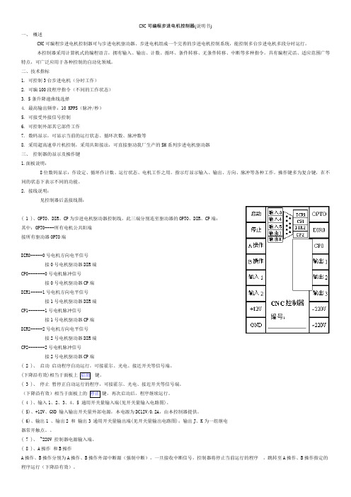
2.接线说明:见控制器后盖接线图:( 1 )、OPTO、DIR、CP为步进电机驱动器控制线,此三端分别连至驱动器的OPTO、DIR、CP端:其中:OPTO----所有电机公共阳端接所有驱动器OPTO端DIR0-----0号电机方向电平信号接0号电机驱动器DIR端CP0-------0号电机脉冲信号接0号电机驱动器CP端DIR1-----1号电机方向电平信号接1号电机驱动器DIR端CP1-------1号电机脉冲信号接1号电机驱动器CP端DIR2-----2号电机方向电平信号接2号电机驱动器DIR端CP2-------2号电机脉冲信号接2号电机驱动器CP端( 2 )、启动启动程序自动运行,可接霍尔、光电、接近开关等信号端。
(下降沿有效)相当于面板上键。
( 3 )、停止暂停正自动运行的程序,可接霍尔、光电、接近开关等信号端。
(下降沿有效)相当于面板上的键,再次启动后,程序继续运行。
舵机板说明书
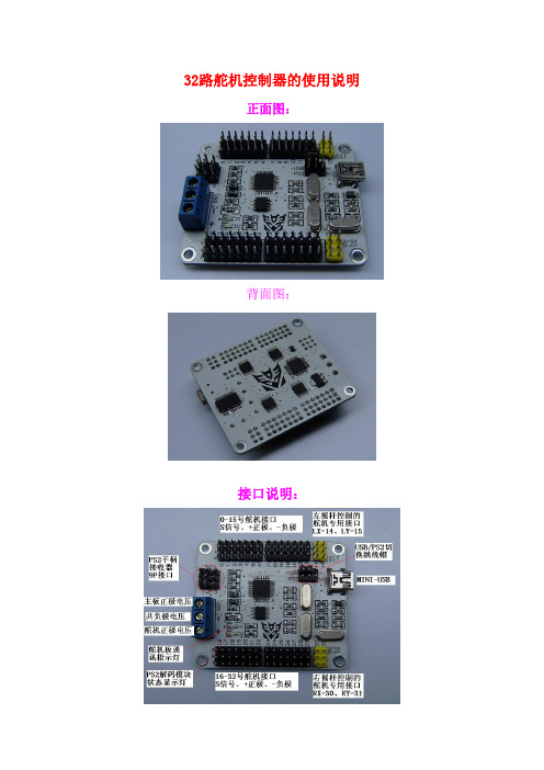
32路舵机控制器的使用说明正面图:背面图:接口说明:1、安装驱动使用MINI-USB线连接上舵机板找到以下的驱动,这里可跳过安装然后打开QSC-32E(PL2303)驱动文件夹双击PL2303 Driver 来手动安装驱动程序如果是WIN7系统需要进行如下操作:鼠标右键单击此文件选择属性弹出如下窗口:然后选择兼容性窗口再这里的用兼容性模式运行这个程序打上勾再下拉窗口中选择WINXP,我这里使用的本身已经是WINXP系统所以无此选项使用者选择WINXP即可然后点击确定退出该窗口然后重新双击驱动软件便可在WIN7模式下用兼容模式安装WINXP的驱动程序2、安装 Framewoks2.0,如果已经安装了或者有高版本的NetFramewoks 文件可跳过安装,如果没有安装这个文件则打不开上位机软件,如果能直接打开上位机软件则可不安装此文件。
WIN7或以上操作系统可直接跳过安装。
3.上位机软件说明左边为舵机图标操作窗口,打钩显示该舵机口、取消就关闭该舵机口右边为舵机图标位置保存窗口,舵机图标可自由拖拉,拖拉后保存位置舵机图标窗口,可自由拖拉如下人形的图标窗口,然后保存位置保存的位置一定要跟上位机软件QSC舵机控制器同一个目录下,以后才能从选择那里直接打开,保存到其他文件夹无效COM口选择端默认通讯速度为高速模式115200 特殊情况下使用低速模式9600动作组调试运行窗口,上面是调试窗口下面是运行窗口初始化:上位机软件初始化,表示从开始地址256号位置开始写动作,只是对软件操作,而不改变已经下载到主板上的动作擦除:对下载到主板上的动作组做清空操作运行动作组:运行已经下载到主板上的动作组停止:停止运行动作组脱机动作组:运行已经下载到主板上的动作组并且下次开机直接执行该动作组禁用:禁用脱机动作组功能舵机口指示条也随意拖动B表示舵机偏差(默认为0),即舵机的相对位置范围为-100----100P表示舵机位置(默认为中位1500)范围为500-2500而导入动作组中的是绝对位置P0=B+P在上图中:#表示几号舵机;P表示舵机的位置;T表示舵机运行到该位置的时间串口发送接收区输入代码点击发送按键即可调试好的舵机偏差值B 跟动作文件P 的保存操作窗口B跟P需要独立保存打开使用也需要独立操作不能用P的打开窗口打开B保存好的文件。
- 1、下载文档前请自行甄别文档内容的完整性,平台不提供额外的编辑、内容补充、找答案等附加服务。
- 2、"仅部分预览"的文档,不可在线预览部分如存在完整性等问题,可反馈申请退款(可完整预览的文档不适用该条件!)。
- 3、如文档侵犯您的权益,请联系客服反馈,我们会尽快为您处理(人工客服工作时间:9:00-18:30)。
QSC24ENANO可编程控制舵机板使用说明要点
1.引言(100字):
2.特性(200字):
QSC24ENANO支持最多24个舵机,每个舵机都有独立的PWM输出。
它采用高性能的STM32F030C8T6单片机,内置四通道驱动芯片,可直接驱动舵机,无需其他设备。
该板还支持通过I2C总线进行网络扩展,可同时驱动多块扩展板。
3.连接方法(200字):
首先,将QSC24ENANO插入主控制器的GPIO引脚,并连接电源。
接下来,将舵机的信号线插入QSC24ENANO的相应引脚上,确保舵机的电源线和地线与QSC24ENANO相连接。
最后,连接其他扩展板或外设,如传感器或显示屏。
4.控制方式(300字):
可以通过多种方式控制QSC24ENANO,包括手动控制、编程控制和远程控制。
手动控制可以通过按钮、滑块或旋钮等输入设备实现。
编程控制可以使用C、C++、Python等语言编写程序,通过串口或无线模块将程序加载到主控制器上。
远程控制可以使用红外遥控器或无线控制器等遥控设备,通过无线通讯方式与QSC24ENANO通信。
5.编程方法(400字):
QSC24ENANO可通过多种编程方法进行控制。
首先,可以使用官方提供的库函数进行编程,该库函数提供了丰富的API接口,方便用户进行开发和控制。
其次,支持通过Arduino IDE进行编程,用户可以选择适合自
己的开发环境和编程语言。
此外,还可以使用ROS(机器人操作系统)进行编程,ROS提供了强大的工具和库,方便用户进行机器人控制和协作开发。
在编程过程中,用户可以根据实际需求对舵机进行控制。
可以控制舵机的位置、速度和加速度等参数,还可以进行运动轨迹规划和复杂动作序列控制。
用户还可以通过编程实现舵机的同步运动、互动控制和多舵机协同等功能。
6.实例应用(200字):
QSC24ENANO可广泛应用于机器人、航模和其他遥控应用。
在机器人领域,可以用于控制机器人的关节和执行器,实现机器人的运动和动作。
在航模领域,可以用于控制飞机、直升机和无人机等的舵机,实现精确操控和飞行控制。
在其他遥控应用中,可以用于控制车辆、船只、摄像云台等设备,实现远程操控和平稳运动。
总结(100字):
通过本文的介绍,您应该了解到QSC24ENANO可编程控制舵机板的特性、连接方法、控制方式和编程方法等要点。
它具有丰富的功能和灵活的应用,适用于各种机器人、航模和遥控应用。
希望本文对您使用
QSC24ENANO有所帮助,祝您开发顺利!。