甲烷CH4气体报警器使用规范 说明书
可燃气体检测仪操作说明书及注意事项
XP-3140(单一气体CH4高量程)使用:一、使用程序:装入电池-打开电源-预热运转(显示预热画面ADJ)-检测(显示检测画面)-关闭电源二、注意事项1、必须在洁净空气中接通电源,如气体浓度显示不为零(浓度显示闪烁或上升),则需按AIR键(约按3秒)进行零位调整,显示浓度为零后方可进行检测。
2 切断电源时,返回到洁净空气中,待气体浓度下降后再关闭电源。
3、不得堵塞进气口和排气口4、夜间使用时可按LIGHT键5、此款可燃气体报警器为高量程,可检测可燃气体浓度为0-100%vol(CH4在混合气体中的体积比)。
GASALERTMICROCLIP(四合一)便携式报警器使用一、使用程序:充电-打开电源-进行自检-检测-关闭电源二、注意事项1、此款报警器甲烷检测范围为0-100%LEL(爆炸下限5% vol的百分比),氧气的检测范围为0-30% vol,硫化氢的检测范围为0-100ppm (危险浓度为20ppm),一氧化碳的检测范围为0-500ppm。
2、夜间使用时,可按控制键,背景灯亮。
3、只有显示TEST OK 后方可进行检测。
4、自校零。
在清洁空气环境下,按住○直至屏幕出现OFF倒计时,屏幕暂时关闭时继续按住○。
检测仪此时显示CAL倒计时,按住○直至倒计时完成并进入校准状态。
此时屏幕闪烁,检测仪开始将所有传感器归零,并对氧气传感器进行校准。
5、严禁超量程使用。
6、GASALERTMICROCLIP(单一气体CH4微量)使用方法同上。
GASALERTMICRO(四合一)便携式报警器使用一、使用程序:安装电池-打开电源-进行自检-检测-关闭电源二、注意事项1、此款报警器甲烷检测范围为0-100%LEL(爆炸下限5% vol的百分比),氧气的检测范围为0-30% vol,硫化氢的检测范围为0-100ppm (危险浓度为20ppm),一氧化碳的检测范围为0-500ppm。
2、只有显示TEST 后方可进行检测。
甲烷检测报警器的使用方法

书山有路勤为径,学海无涯苦作舟
甲烷检测报警器的使用方法
很多人对于甲烷检测报警器的使用方法都不是很理解,今天我为大家描述下JCB4 型甲烷检测报警器的使用方法,希望能给大家带来帮助。
1、按键功能甲烷检测报警器按键功能如下:
1)开关键:当仪器处于关机状态,长按该键仪器开启;当仪器处于开机状态,并且未处于设置状态时,长按该键仪器关机;当仪器处于设置状态时,作为数据递减键;
2)电压键:当仪器处于开机状态时,按该键仪器显示电池电压;子啊系统设置、仪器调校时,作为数据递增键;
3)设置键:当仪器处于开机状态,长按该键仪器进入设置状态;的那在系统设置、仪器调校时,作为确认键。
2、系统设置及调校
甲烷检测报警器设置或调校前应保证仪器处在稳定状态或开机预热10 分钟
后进行。
1)校零:长按设置键3 秒,仪器进入设置状态,数码管显示1。
按设置确认。
听到嘀的一声,即校零完毕。
注:
甲烷检测报警器校零必须在清洁的空气中进行。
当环境空气清洁度达不到校零的要求时,数码管显示ERR,禁止校零。
2)标定:在设置状态下,使用电压或开关键调整,使数码管显示2,按设置
确认,听到嘀的一声,进入标定状态,此时数码管显示的数值为上次标定的数值。
使用电压或开关键,调整到本次标定的标准气样数值,按设置键确认后即退出标定状态,回到设置状态。
JCB4便携式甲烷检测报警仪使用说明书
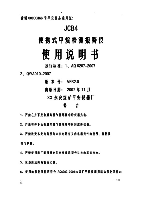
- .渝制00000866号平安标志准用证:JCB4便携式甲烷检测报警仪使用说明书执行标准:1、AQ 6207-20072、Q/YA010-2007版本号:VER2.0出版日期:2007年11月XX永安煤矿平安仪器厂警告1、严禁在井下及有爆炸性气体环境中给仪器充电。
2、严禁在井下及有爆炸性气体环境中拆卸维修仪器。
3、严禁改变本安电路及与本安电路有关的电器元件的型号、规格及电气参数。
4、严禁使用出厂时所规定的电池规格型号以外的其它电池。
5、仪器应远离高温及火源。
6、使用的催化元件应符合AQ6202-2006<<煤矿甲烷检测用载体催化元件>> - . 可修的规定,且应有有效期内的平安标志准用证。
7、使用时必须佩动物皮套使用。
一、概述1、产品的主要特点:JCB4型便携式甲烷检测报警仪是我厂在吸取国内外同类产品之根底上精心设计、研制的新一代高智能化产品,它具有如下特点:测试精度高、反响灵敏、稳定可靠、自检功能强〔电池电压自检、报警点设定自检、催化元件灵敏度自检〕,自动校零,超限报警,实时显示瓦斯浓度,保护催化元件不受高浓瓦斯冲击,电池电压欠压预警,欠压自动关机,开关机按键时间长,确保不误开机和误关机。
大容量高性能可充电镍氢电池,整机工作时间可长达12小时,电池无记忆,可随时充电。
电池保护采用新型自恢复保护器件,短路后不发热、不过流。
仪器充电采用限压恒流充电原理,延长电池使用寿命。
本仪器操作简单,体积小,重量轻〔仅150g〕,维护修理十分简便等特点。
2、仪器用途:JCB4型便携式甲烷检测报警仪为矿用本质平安兼隔爆型,防爆标志ExibdI,主要用在有瓦斯的矿井或其它有瓦斯的环境中,用于快速检测瓦斯浓度。
二、仪器型号、编制方法、执行标准2.1执行标准AQ 6207-2007、Q/YA010-20072.2产品型号J C B4测量X围〔0.00~4.00〕%CH4便携式热催化甲烷检测报警仪三、主要技术参数:1、工作条件a) 环境温度为(0~+40)℃;b) 海拔高度不超过2000m;c) 环境大气压为〔80~116〕KPa;d) 相对湿度≤98%(25℃时);e) 具甲烷混合物及煤尘爆炸危险的煤矿井下;f) 在无破坏绝缘的气体或蒸汽的环境中;g) 在无滴水的地方;h) 风速≤8m/s的环境中。
便携式甲烷报警仪使用管理与维修操作规程通用范本

便携式甲烷报警仪使用管理与维修操作规程通用范本一、引言便携式甲烷报警仪是一种用于检测空气中甲烷浓度的设备,广泛应用于石油、化工、煤矿等行业。
为了确保便携式甲烷报警仪的正常使用和维护,制定本操作规程。
二、使用管理1. 设备准备1.1 确保便携式甲烷报警仪处于正常工作状态,电池电量充足。
1.2 检查传感器是否干净,无损坏和污染。
1.3 确保报警仪与配套设备(如计算机)连接正常。
2. 操作流程2.1 打开便携式甲烷报警仪电源,待设备自检完成后进入正常工作状态。
2.2 使用仪器操作按钮或触摸屏设置相关参数,如报警阈值、单位等。
2.3 将便携式甲烷报警仪放置在待测区域,确保传感器暴露在空气中。
2.4 实时监测甲烷浓度,当浓度超过设定阈值时,报警仪将发出声光报警信号。
2.5 在使用过程中,注意观察仪器的工作状态,如有异常及时停止使用并进行维修。
3. 注意事项3.1 使用时需佩戴个人防护装备,如安全帽、防护眼镜等。
3.2 避免便携式甲烷报警仪暴露在高温、高湿度、腐蚀性气体等环境中。
3.3 避免剧烈震动和摔落,以免损坏设备。
3.4 定期校准和维护便携式甲烷报警仪,确保其准确性和可靠性。
3.5 禁止私自拆卸或修改设备,如需维修请联系专业人员。
三、维修操作1. 维修前准备1.1 停止使用便携式甲烷报警仪,并将其置于安全位置。
1.2 关闭电源,拔掉电池或断开电源连接线。
1.3 准备必要的维修工具和备件。
2. 常见故障排除2.1 无法开机:检查电池电量是否充足,是否正确连接电源。
2.2 传感器故障:检查传感器是否干净,是否损坏,如有问题需更换传感器。
2.3 报警信号异常:检查报警阈值设置是否正确,是否存在误报情况。
3. 维护保养3.1 定期清洁传感器,避免污染和损坏。
3.2 定期校准仪器,保证测量结果的准确性。
3.3 检查电池电量,确保充足。
3.4 定期检查设备的外观和连接线路,如有损坏及时更换。
四、紧急处理1. 报警信号响起时,应立即停止工作,迅速撤离现场,并采取相应安全措施。
SBS-CH4 甲烷气体探测器安装、操作和维护手册说明书

SBS-CH4Methane Gas Detector KitFor applications and processes where Methane gas may be present INSTALLATION, OPERATION & MAINTENANCEINSTRUCTIONSProtects Life, Property and ProfitsElectrical Safety – UL 61010-1Compliant with NFPA 70E® and IEEE RecommendationsPollution Degree 21-800-554-2243*******************Warnings∙This detector is added protection, not a substitute for prudent safety measures, for where methane gas may be present.∙For large or highly-sensitive areas, SBS recommends installing additional sensors for increased coverage area.∙The methane sensor does not provide protection from fires or methane explosions.The relay contacts are intended to be connected to a safety system that would enable audible alarms, system shutdown and ventilation.∙Ensure that installation complies completely with all relevant Local, State, Federal and OSHA safety and health regulations.∙If a sensor enters warning or alarm mode there is a risk of combustion or explosion. To avoid injury, leave the area immediately.∙The sensor is calibrated for operation in air. Tampering with the sensor or operation in environments that are exposed to other types of gases can lead to inaccuratereadings, false alarms or permanent damage.∙Please see troubleshooting guide for list of gases and compounds that may damage or alter a sensor’s performance.∙Uncured silicone compounds or extended exposure to silicone off gassing can give inaccurate readings or false alarms on a sensor.Table of ContentsDescription Page SectionBenefits 5 2.0Specifications 6 4.0Main Control 7 6.0Operation 12 8.0Testing the Sensor 13 10.0Main Unit and Accessories Part No. DescriptionSBS-CH4Methane Gas DetectorIncludes: one (1) main control, one (1) CH4-SENSOR and one (1) 25 ft. cableCH4-JB Junction Box with Knockouts, 4 11/16" X 4 11/16", MetalCH4-SENSOR Methane Gas Sensor Only (No Cable)CH4-SENSOR-25FT Additional/Replacement Methane Gas Sensor with 25 ft. Cable CH4-SENSOR-50FT Additional/Replacement Methane Gas Sensor with 50 ft. Cable CH4-SENSOR-100FT Additional/Replacement Methane Gas Sensor with 100 ft. CableCH4-TESTKIT Field Test Kit for SBS-CH4Includes: case, regulator, tubing and two (2) cylinders of CH4 gas (25%LEL and 50%LEL)CH4-TESTKIT-INTL Field Test Kit for SBS-CH4Includes: case, regulator and tubing – does not include CH4 gas cylindersE190399110Vac 3 Prong AC Cord, 10 Ft., 18-3 AWG1.0 OverviewAt room temperature and pressure, methane is a colorless, odorless gas.Concentrations of 4.4% to 17% CH4 mixed with air can be explosive. Sparks or hot surfaces can ignite methane gas.The SBS-CH4 methane detector acts as a monitor and provides a visual and audible alarm when methane gas is detected. The unit also has a 25%LEL concentration relay that can trigger exhaust fan operation and a 50%LEL concentration relay that can trigger a building management/alarm system (via SCADA/Modbus) before the gas reaches the lower explosive limit (LEL) of 4.4%.2.0 BenefitsIn addition to protecting employees and property, the detector may also reduce the following costs: Energy EfficienciesInstead of continuously running an exhaust fan to prevent methane gas accumulation, use the detector to activate a fan only if the gas concentration reaches 25%LEL.Insurance SavingsInstallation of a detector in areas where batteries are charged may result in a premium reduction.3.0 How it WorksShould the concentration of methane gas in the air surrounding the sensor reach 25%LEL by volume, the “25%LEL Warning” yellow LED will light up on the main control of the unit. In addition, the25%LEL internal relay will energize and can be used to activate a remote exhaust fan.Should the methane gas concentration reach 50%LEL by volume, the “50%LEL Alarm” red LED will light up, the strobe will flash and an audible alarm will sound. In addition, the 50%LEL internal relay will energize and can be used to activate a building management/alarm system (via SCADA/Modbus). The SBS-CH4 provides automatic operation, continuous detection, high sensitivity, stability and solid-state reliability. The unit uses 120/240 Vac 50/60 Hz and/or 12 - 48 Vdc operating voltages.4.0 SpecificationsDimensions∙Main control: 4.7" L x 4.7" W x 1.2" D∙Sensor: 3.1" L x 1.6" W x 0.87" DMounting∙Wall: two 3/16" screws (not included)∙CH4-JB Junction box: 4 11/16" x 4 11/16" 2-gang junction boxPower Requirements/OptionsWarning: Power requirements for the unit and relays should not exceed min/max specifications ∙120 Vac, 50/60 Hz Nominal (Terminal J8)o93 - 121 Vaco250mA / 10W Max∙220 Vac, 50/60 Hz Nominal (Terminal J8)o185 - 242 Vaco125mA / 10W Max∙12-48 Vdc Nominal (Terminal J9)o9 - 58 Vdco600mA / 6W Maxo Note: An earth ground must be supplied to the GND terminal on the AC terminal block when using only the DC power supplyRelays∙25%LEL Warning Relay (Terminal J6)o 1 Normally Open and 1 Normally Closed contacto Rated for 15 A resistive @ 120 Vaco Rated for 10 A resistive @ 277 Vaco Rated for 10 A resistive @ 28 Vdc∙50%LEL Alarm Relay (Terminal J3)o 1 Normally Open and 1 Normally Closed contacto Rated for 0.5A @ 28 VdcTemperature/Humidity∙Operating Temperature Range: 32°F (0°C) to 122°F (50°C)∙Operating Humidity Range: 20-95% non-condensing∙Storage Humidity Range: 5-95% non-condensingMaximum Altitude∙2000 metersAudible Alarm∙85 dB at 10’ @ 1.6 - 3.2 KHzStrobe LED∙*******************.2V5.0 SensorThe CH4-SENSOR consists of an electronic sensing element whose electrical conductivity increases when Methane is detected at its surface. Conductivity of the sensor is proportional to the gas concentration, which is continuously monitored by the electronic alarm circuits.The sensor is calibrated specifically for methane gas (CH 4) and can detect other combustible gases that it is not specifically calibrated for.6.0 Main ControlSensor HeadStrobe AlarmIndividual Sensor Indicators (For troubleshooting, refer to page 14.)Methane SensorCat5 Cable(25 ft. std., 50/100 ft. optional)Main ControlMain Control Indicators (3 LEDs)7.0 InstallationWARNINGAC voltage relay terminals (120/240 Vac) are located within this detector, presenting a hazard toservice technicians. Only qualified technicians should open the detector case and service the internal circuits. Ensure power is removed from the detector relays prior to servicing the unit. Failure to do so may result in injury or death.Mounting and Power OptionsAlarm WiringCH4-JB Junction Box Mountable (optional) Mounts to a standard, 4 11/16" x 4 11/16" 2-gang junction boxHardwire OptionRun AC and/or DC power and alarm wires through back of the unit, into the gang box and out through conduit.E190399 AC Line Cord3-prong grounded AC cord, 18-3 AWGWall MountableIntegrated back mounting plate allows user to easily mount directly to any wall using 3/16" screws (not included).WiringPower and alarm wires can run through the sides of the unit.Input PowerMounting LocationMethane is colorless and odorless; the leaks from a refrigerated liquid container are heavier than air due to increased density of the cold gas, however the gas at ambient temperature is lighter than air and thus rises. The sensor should be installed in proper location for detection of leaking liquid gas, or rising ambient temperature gas accumulation.The detector measures methane gas concentration in the air immediately surrounding the sensor’s surface. The area one sensor will monitor depends on the properties of the compartment or room. Methane gas may accumulate in several areas of the compartment or room and multiplesensors/detectors may be necessary depending upon construction and design of the application.The main control can be mounted wherever is convenient for the user, but should be within the cable length range to connect to each sensor.The sensor should be mounted at the location where leak detection or gas concentration buildup is to be monitored. Each sensor connects with the main control via the cable.Carefully remove the main control cover by removing the two screws located on the front of the cover. Attach the main control to the wall, ceiling or optional junction box using the mounting holes at the top and bottom of the main control’s mounting plate.After the power and relay wiring is complete, connect each cable from main control to each sensor and refasten the main control cover.Power OptionsThe detector has terminal blocks for connections to a single-phase 120/240 Vac 50/60 Hz power source (Terminal J8), and/or a 12-48 Vdc power source (Terminal J9). The power supply inputs are redundant, so the unit can use the DC input as a backup source.RelaysThe detector has two (2) internal alarm relays:∙25%LEL warning relay (Terminal J6) is activated when a sensor detects 25%LEL concentration of methane gas. The 25%LEL relay’s dry contacts are rated at 10A/250 Vac,sufficient for most 1/3 HP exhaust fans.∙50%LEL alarm relay (Terminal J3) is activated when a sensor detects 50%LEL concentration of methane gas. The 50%LEL relay’s dry contacts are rated for 0.5A/28 Vdc.∙Note: For higher current requirements, add an external relay.Mounting OptionsJunction Box MountedFor 120/240 Vac power, use 18-3 gauge stranded wire.For 9 - 58 Vdc power, use 18-2 conductor insulated wire.For relay wires, use stranded wire. Maximum wire size for connector terminations is 14 AWG. Stranded conductors must be terminated in a manner to prevent shorting from one terminal to another by a loose strand. Tin the wires with solder if required.Wall MountedFor 120 Vac power, an 18-3 gauge insulated line cord is required.For 9 - 58 Vdc power, use 18-2 conductor insulated cable from the DC supply.For relay wires, use stranded wire. Maximum wire size for connector terminations is 14 AWG.Disconnection of Supplying PowerWhen the unit is hard wired, an external 10 Amp (minimum) circuit-breaker or switch should be installed to act as a disconnecting device. The circuit-breaker must open all supply conductors simultaneously, be easily reached by operators and be marked as the disconnecting device for the equipment.For Installation of Additional SensorsA maximum of three (3) sensors may be connected to each main control. Multiple detectors and sensors can be installed to meet the space coverage requirements of your particular installation.Locate the additional sensors ’ installation points within cable reach of the main control and mount the sensor. Connect the cables from any additional sensors to the Sensor 2 and Sensor 3 inputs on the main control.SBS supplies a tie-wrap to secure the AC mains ’ wiring. The tie wrap can rotate up to 270 degrees to accommodate your installation.Alarm System ElectronicsPlease refer to the illustration below to identify proper power and relay connection points in the detector. It is advisable to use a pair of 14 gauge or smaller stranded wire for the relay contacts to help reduce any interference within the area that may cause false alarms.Each of the Cat5 sensor input connections has a status indicator LED on the main control, which will illuminate solid green when a sensor is connected and operating normally. A sensor’s corresponding LED will flash at the same rate as the strobe LED when detecting 25%LEL or 50%LEL CH4 concentration. The LED for a sensor that is in alarm mode will flash at the same rate as the strobe LED. The alarming sensor and strobe LED will flash at a faster rate than the LED for a sensor that is only in warning mode.Terminal Connection DiagramUsing the Mechanical Relays1. Remove the front cover of the main control by removing two fix screws and pulling straight offthe body. This will reveal the inner electronics of the alarm box.2. Locate the terminal blocks for the relays and determine which condition you would like therelay to be related to. Use the 25%LEL relay (Terminal J6) for the warning condition and the 50%LEL relay (Terminal J3) for the alarm condition.3. Replace the front cover on the alarm box.8.0 OperationKeep the detector on at all times. The solid green LED for ‘POWER’ on the main control indicates that the detector is powered on.When power is first turned on, a warm up period of 30 seconds will elapse before the unit will function. This delay is to prevent false activation of the internal relays and alarm.Should the concentration of methane gas in the air surrounding the sensor reach 25%LEL by volume, the “25%LEL Warning” yellow LED will light up on the main control of the unit. In addition, the25%LEL internal relay will energize and can be used to activate a remote exhaust fan.Should the methane gas concentration reach 50%LEL by volume, the “50%LEL Alarm” red LED will light up, the strobe will flash and an audible alarm will sound. In addition, the 50%LEL internal relay will energize and can be used to activate a building management/alarm system (via SCADA/Modbus).ConditionMain ControlIndicatorsPower Warning AlarmIndividual SensorIndicatorsRelayClosureAudibleAlarmStrobeNormal Operation(sensor installed)None None NoneCH4 Warning(25%LEL CH4)(blinking green)WarningRelayEnergizedNone NoneCH4 Alarm(50%LEL CH4)(same flash rate as strobe)Warning andAlarm RelayEnergizedON ONSensor/Cable Fault None None NoneCommunicationwith Sensor Lost(plugged in, but not lit)None None NoneMain Control IndicatorsIndividual Sensor Indicators9.0 Electrical TestingA "TEST" button is located on the front of the main control. Push and hold this button for approximately 10 seconds to test the unit's electronic circuitry.The warning and alarm LEDs will light up in sequence, the strobe will flash, the relays will activate whatever is connected to them and the internal warning alarm will sound.Note: The "TEST" button does NOT test the sensor(s) itself –only the unit’s electronic circuitry.10.0 Testing the SensorThe sensors and main controls are factory calibrated. It is recommended to test each sensor’s functionality every 12-18 months with the CH4-TESTKIT.The CH4-TESTKIT is intended for periodic testing of the functionality and proper operation of the system. Once a sensor is installed, calibration or adjustment of the sensor is not possible. Please contact your sales representative if sensor calibration is desired or required.The CH4-TESTKIT includes the following:∙25%LEL (17 liters) CH4 in air calibrated gas canister∙50%LEL (17 liters) CH4 in air calibrated gas canister∙Regulator∙Flexible tubing with sensor head adapterTesting the 25%LEL Warning and 50%LEL Alarm State1. Connect the test fixture to the 25%LEL CH4 air gas cylinder.2. Secure the test fixture to the sensor module connected to sensor by pressing the flexible tubingcompletely over the inlet to the sensor head.3. Turn on the gas flow by slowly cracking then fully opening the valve completely. Please wait 60seconds to ensure the air in the tubing has been purged.4. Continue gas flow and wait for the yellow LED warning to light up and the 25%LEL relay toenergize.5. Turn off gas and remove from sensor.6. Repeat Steps 1-5 above using the 50%LEL CH4 air gas cylinder to activate the 50%LEL alarmand relay. The 50%LEL alarm threshold is connected to the red LED, the audible alarm and the strobe light up, which will activate during testing.7. Repeat steps for every sensor installed.Note: If the unit does not alarm during these tests the sensor may need to be replaced.Replacing the SensorIn a typical operating environment SBS recommends that each sensor be replaced every three years. An abusive operating environment can and will shorten a unit’s useful life. In dusty/dirty applicationsor in situations where a sensor is often subjected to different gases, it is recommended to replace each sensor after one (1) year.11.0 Troubleshooting and MaintenanceNo PowerVerify the AC and/or DC power cables are installed per the connection diagram on page 11.RelaysThe SBS-CH4 system was designed for the relays to operate in a failsafe condition when the power supply is interrupted. If the fan connected to a relay runs as soon as the unit is powered on, the unit has been wired for the use of the Normally Open contact instead of a Normally Closed contact.False AlarmsEach sensor has been calibrated for the detection of methane gas, however any combustible gas that comes in contact with a sensor has the potential to activate the warning and/or alarm relays. Contact with any individual or combination of the following gases could trigger false alarms and/or contaminate a sensor.Gases include but are not limited to:-Acetone-Acetylene-Ammonia-Benzene-Butane-n-Butyl Acetate -Carbon Dioxide -Carbon Monoxide -Ethane-Ethanol-Ethyl Acetate -Ethyl Ether-Ethyl Oxide-Gasoline-Heptane-Hexane-Isopropyl Alcohol-Methane-Methane Cyanide-Methane Sulfide-Methanol-Methyl Ethyl Ketone-Nitric Oxide-Nitric Dioxide-Propane-Propylene Oxide-Styrene-Sulfur Dioxide-Toluene-Turpentine-Vinyl Acetate-XyleneIf a sensor’s warning or alarm condition is reached, ventilate the area with clean air. This should reduce the concentration of most gases and the warning or alarm condition should clear.Note - when a warning occurs at 25%LEL, the warning will not clear until concentrations drop below 0.5%. Similarly, when an alarm occurs at 50%LEL, the alarm will not clear until concentrations drop below 1.5%.Avoid installation in highly corrosive environments where high densities of Methane sulfide, sulfur oxide, chlorine, Methane chloride, etc. may be present. These gases can cause corrosion of the element and the power leads to the circuit board.A sensor’s output characteristics can be affected if the sensor becomes contaminated or exposed to heavy alkaline metals.A sensor cannot operate in a zero or low oxygen content atmosphere.If a sensor collects water condensation, its characteristics may temporarily drift. However, light levels of condensation under normal indoor use should not pose a significant problem with performance.StorageThe longer a sensor is stored prior to being energized, the longer the warm up and stabilization period may become. Storage Humidity Range: 5 - 95% non-condensing.Maintenance TipsTo maintain the unit, it is recommended to:1. Test the detector once a month by pressing the ‘TEST’ button.2. Vacuum the alarm cover once a month to remove accumulated dust.3. Never use detergents or solvents to clean the unit or sensor. Chemicals can permanentlydamage or temporarily contaminate a sensor.4. Avoid spraying air fresheners, hair spray, paint or other aerosols near a sensor.5. Never paint the unit or sensor. Paint will seal the vents and interfere with proper sensoroperation.WARNINGSDo not disassemble unit or attempt to repair or modify any component of this instrument. This instrument contains no user serviceable parts, and substitution of components may impair intrinsic safety, which may adversely affect product performance and result in injuryThe SBS-CH4 Methane Alarm System is not a standalone safety device and does not provide protection from methane explosions. The relay contacts are intended to be connected to a safety system, enabling audible alarms, system shutdown, ventilation, or other measures to ensure monitoring of methane gas occurs before concentrations reach dangerous levels.The information in this sheet has been carefully reviewed and is believed to be accurate; however, no responsibility is assumed for inaccuracies. Storage Battery Systems, LLC reserves the right to make changes without further notice to any product, datasheet, technical data bulletin, or website.Storage Battery Systems, LLC makes no warranty, representation of guarantee regarding the suitability of its product for any particular purpose, nor does Storage Battery Systems, LLC assume any liability arising out of the application or use of any product and specifically disclaims any and all liability, including without limitation consequential or incidental damages. “Typical” parameters can and do v ary in different applications. All operating parameters, including “Typical” must be validated for each customer application by customer’s technical experts.Storage Battery Systems, LLC products are not designed, intended, or authorized for use in any application in which the failure of the SBS product could create a situation where personal injury or death may occur.Should buyer purchase or use SBS products for any such unintended or unauthorized application, Buyer shall indemnify and hold Storage Battery Systems, LLC and its officers, employees, subsidiaries, affiliates, and distributors harmless against all claims, costs, damages, and expenses, and reasonable attorney fees arising out of, directly or indirectly, any claim of personal injury or death associated with such unintended or unauthorized use, even if claim alleges that Storage Battery Systems, LLC was negligent regarding the design or manufacture of the part.In the case of a defect in the sensor, Storage Battery Systems, LLC shall not be liable for any damages which may result, including, but not limited to, loss of revenue, property, or life. In an event, Storage Battery Systems, LLC shall limit liability to replacement of the defective unit. Storage Battery Systems, LLC does not convey any license under its patent rights nor the rights of others.。
甲烷报警仪调控操作规程
甲烷报警器的调节和操作程序
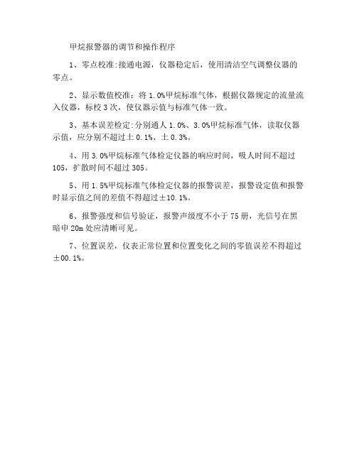
1、零点校准:接通电源,仪器稳定后,使用清洁空气调整仪器的零点。
2、显示数值校准:将1.0%甲烷标准气体,根据仪器规定的流量流入仪器,标校3次,使仪器示值与标准气体一致。
3、基本误差检定:分别通人1.0%、3.0%甲烷标准气体,读取仪器示值,应分别不超过土0.1%、土0.3%。
4、用3.0%甲烷标准气体检定仪器的响应时间,吸人时间不超过105,扩散时间不超过305。
5、用1.5%甲烷标准气体检定仪器的报警误差,报警设定值和报警时显示值之间的差值不得超过±10.1%。
6、报警强度和信号验证,报警声级度不小于75册,光信号在黑暗申20m处应清晰可见。
7、位置误差,仪表正常位置和位置变化之间的零值误差不得超过±00.1%。
甲烷报警仪调控操作规程

甲烷报警仪调控操作规程背景甲烷是一种易燃易爆的气体,常被认为是矿井和工厂等危险场所中存在的主要隐患之一。
为了确保工作场所的安全性,甲烷报警仪被广泛应用于工厂、矿井等危险场所。
甲烷报警仪是一种用于检测空气中甲烷浓度的设备,一旦检测到空气中甲烷浓度超过一定阈值,报警仪会发出警报,提醒操作人员及时采取措施,以避免潜在的危险。
为了确保甲烷报警仪能够正常运作,需要按照一定的操作规程进行调控。
本文档就是为了介绍甲烷报警仪的调控操作规程。
操作流程步骤一:准备工作在调控甲烷报警仪之前,需要先进行以下准备工作:1.清洁甲烷报警仪,确保其表面干净无尘。
2.检查甲烷报警仪的电源是否正常,并确保其连接稳定。
3.确保甲烷报警仪的传感器齐全且安装正确。
完成以上准备工作后,方可进行甲烷报警仪的调控。
步骤二:设置甲烷报警仪的警报阈值甲烷报警仪的警报阈值是指该设备检测到空气中甲烷浓度超过该阈值时所发出的警报。
不同场所的甲烷浓度阈值不尽相同,为确保甲烷报警仪能够在实际场所中得到有效的应用,需要进行如下设置:1.按下甲烷报警仪的“设置”按钮,进入设置模式。
2.在设置模式中,按下“警报阈值”按钮。
3.通过按“+”或“-”按钮来调节警报阈值,直至其符合实际场所的需求。
完成以上步骤后,甲烷报警仪的警报阈值就被成功设置。
步骤三:测试甲烷报警仪的警报效果为确保甲烷报警仪在实际使用中能够正常发出警报,需要对其进行测试,具体操作步骤如下:1.在实际使用场所中,向甲烷报警仪所在区域放置一些甲烷浓度较高的物品,使得其能够检测到空气中存在甲烷。
2.检查甲烷报警仪的操作状态是否正常,并确保其处于警报模式。
3.等待约10-20秒,观察甲烷报警仪是否发出了警报。
若发出了警报,则说明其警报效果良好。
步骤四:保养甲烷报警仪为确保甲烷报警仪的长期稳定运作,需要进行定期保养,具体操作如下:1.定期对甲烷报警仪的外部进行清洁,确保其表面干净无尘。
2.定期对甲烷报警仪的传感器进行校准,以确保其检测精度和准确度。
便携式甲烷报警仪使用管理与维修操作规程范本

便携式甲烷报警仪使用管理与维修操作规程范本第一章总则第一条为了规范便携式甲烷报警仪的使用管理与维修操作,确保设备的正常运行和使用安全,制定本规程。
第二条本规程适用于公司内部所有便携式甲烷报警仪的使用、维修人员,包括运维人员和维修工程师。
第三条本规程的内容包括便携式甲烷报警仪的安全用电、保养、维修和事故处理。
所有相关人员必须遵守本规程的要求。
第四条便携式甲烷报警仪维修工程师必须具备相关的技术和培训证书,并定期参加培训。
第五条严禁未经授权的人员擅自拆解、更改、修理便携式甲烷报警仪。
第二章安装与使用第六条便携式甲烷报警仪的安装必须遵循安全操作规程,并确保设备连接稳固、线路接地可靠。
第七条使用人员在使用便携式甲烷报警仪前,应仔细阅读设备的说明书,并按照说明书的要求正确操作。
第八条使用人员在使用便携式甲烷报警仪时,需佩戴个人防护装备,包括防护手套、防护眼镜等。
严禁将设备用于非指定的工作环境。
第九条使用人员在使用便携式甲烷报警仪时,需定期检查设备的电量和存储容量,并及时更换电池或清理存储器。
第十条使用人员在使用便携式甲烷报警仪时,如发生设备故障或异常情况,应立即停止使用,并及时向维修人员报告。
第三章保养与维修第十一条便携式甲烷报警仪的保养需定期进行,包括设备的清洁、检查和校准。
第十二条保养人员在进行设备保养时,应按照说明书的要求进行,严禁使用不符合要求的清洁液和工具。
第十三条保养人员在进行设备保养时,应遵循安全操作规程,并戴上相应的个人防护装备。
第十四条设备维修工程师在进行设备维修时,应具备相关技术和培训证书,并遵循维修操作规程。
第十五条设备维修工程师在进行设备维修时,应按照维修手册的要求进行,不可随意更换设备零部件。
第十六条设备维修工程师在进行设备维修时,应仔细记录维修过程和维修结果,并及时向上级报告。
第四章事故处理第十七条便携式甲烷报警仪在使用中如遇到设备故障、失效或其他异常情况时,应立即停止使用,并及时向上级报告。
便携式甲烷报警仪使用管理与维修操作规程

便携式甲烷报警仪使用管理与维修操作规程
一、设备介绍
便携式甲烷报警仪是一种小型、轻便、易于携带的气体探测仪器,主要用于监测甲烷气体浓度的变化并发出警报以保障人员生命
安全和财产的安全。
该设备采用超低功耗设计,能够长时间持续工作。
同时,该仪器也具有防水、防尘和抗震性能,适用于各种场合
中使用。
二、使用管理
1. 报警仪的存放和运输应注意避免受湿、受热、受冲击、挤压
和震动等影响,保持制造商提供的原始包装;
2. 使用前应检查仪器的表面是否有划痕、损坏等情况,并确认
其电池电量是否充足;
3. 在使用报警仪时应穿戴适当的防护用品,如手套、安全鞋等;
4. 报警仪的使用环境一定要与使用说明书的标定环境相匹配,
不得使用在低于或高于其标定环境的情况下;
5. 在使用仪器时应确保仪器接触的环境为无阻挡的空气环境,
避免接触水雾、烟雾、油雾等不利于仪器灵敏度和准确性的气氛环境;
6. 使用后,应将其放置在存放盒中,避免受到湿度、温度等影响,并定期检查仪器的状态。
三、维修操作规程
1. 在维修操作前,应切断报警仪的电源,并将其从使用环境中移除;
2. 维修操作应由具有相关专业知识和技能的人员进行,且应更换原厂配件;
3. 维修操作前应检查维修场所是否符合安全要求;
4. 维修操作中应注意防止电路板等脆弱部件的损坏,并确保拆卸和组装的步骤正确;
5. 维修后应进行实验检测和质量控制,确保报警仪维修后的准确性和可靠性。
便携式甲烷检测报警仪使用及管理制度

便携式甲烷检测报警仪使用及管理制度引言随着城市化进程的发展,能源的需求日益增加,天然气也逐渐成为人们生活中不可或缺的一部分。
但是,天然气的泄漏也时有发生,一旦泄漏不及时发现,将会可能引起火灾、爆炸或中毒等严重后果。
因此,使用便携式甲烷检测报警仪,对于保障人们的安全具有非常重要的作用。
便携式甲烷检测报警仪的使用规定1. 检测时机1.在使用燃气设备之前,需先使用甲烷检测报警仪检测周围环境中的甲烷浓度。
2.当燃气设备使用后,应及时使用甲烷检测报警仪对周围环境中的甲烷浓度进行检测。
3.在燃气设备长时间未使用或燃气管道维修后,重启后需使用甲烷检测报警仪对周围环境中的甲烷浓度进行检测。
2. 检测流程1.打开甲烷检测报警仪开关,等待2-3秒,等待报警仪自检完成。
2.将甲烷检测报警仪朝向需要检测的区域,持续检测,直至检测流程完成。
3.如果甲烷浓度达到警戒值,则甲烷检测报警仪会发出报警信号,提醒人们注意安全。
3. 使用安全注意事项1.检测过程中不能使用明火和火源。
2.不能把甲烷检测报警仪与其它电器连接到同一电线插座上。
3.不能把甲烷检测报警仪放置在高温和潮湿环境中。
4.不能在高温和日光直射的地方存放甲烷检测报警仪。
5.如果甲烷检测报警仪在使用过程中出现故障、损坏或误差变大,应该及时更换或维修。
便携式甲烷检测报警仪的管理制度1. 甲烷检测报警仪购置1.甲烷检测报警仪应该从正规渠道购置,确保质量和有效性。
2.购置的甲烷检测报警仪应该有统一编号,是唯一的个体,方便管理维护。
3.购置的甲烷检测报警仪应该符合国家相关标准。
2. 甲烷检测报警仪维护1.定期检测甲烷检测报警仪的工作性能和准确性。
2.定期更换甲烷检测报警仪的电池。
3.对甲烷检测报警仪进行定期校准和维护,确保检测的准确性和可靠性。
3. 甲烷检测报警仪存放1.把甲烷检测报警仪存放在通风干燥、低温、不受阳光直射的地方。
2.存放的甲烷检测报警仪要与其它电器隔离开来,以免互相干扰。
2023年便携式甲烷报警仪使用管理与维修操作规程

2023年便携式甲烷报警仪使用管理与维修操作规程便携式甲烷报警仪使用管理与维修操作规程第一章总则第一条为了规范便携式甲烷报警仪的使用管理与维修操作,确保工作场所的安全生产,特制定本规程。
第二条本规程适用于所有使用便携式甲烷报警仪的单位和人员。
第三条便携式甲烷报警仪的使用管理与维修操作应符合国家相关法律法规和标准的要求,并依据本规程执行。
第四条本规程应由单位安全管理部门负责组织实施,相关人员应接受相关培训并持有效资格证书。
第五条便携式甲烷报警仪的维修操作必须由具备相应资质和经验的人员进行,同时应使用规定的工具和设备,严禁私自拆卸和修理。
第二章使用管理第六条便携式甲烷报警仪的使用前应进行检测,确认仪器状态正常后方可投入使用。
第七条使用人员应熟悉便携式甲烷报警仪的外观、功能、使用方法及注意事项,并按照说明书正确使用。
第八条使用人员应随身携带并正确佩戴便携式甲烷报警仪,在有毒有害气体环境中进行实时监测。
第九条便携式甲烷报警仪的操作人员应随时关注仪器显示和报警情况,一旦报警应立即采取相应措施,并上报相关部门。
第十条使用人员应定期进行便携式甲烷报警仪的维护保养工作,保持其良好的工作状态,并记录维护保养情况。
第十一条便携式甲烷报警仪的使用环境应保持洁净、干燥,并防止灰尘和湿气进入仪器内部。
第十二条便携式甲烷报警仪的存放应放置在干燥、通风的地方,避免阳光直射和降水,防止撞击和挤压。
第十三条使用单位应建立便携式甲烷报警仪的档案,包括购置台账、使用记录、维护保养记录和检测结果等。
第十四条对于使用过程中损坏的便携式甲烷报警仪,应及时停止使用并上报,由专业维修人员进行检修,并记录维修情况。
第三章维修操作第十五条便携式甲烷报警仪的维修操作必须在无电源、无气源、无高温等危险环境下进行。
第十六条维修人员在维修操作前应检查维修工具和设备是否齐全,确保工具的安全可靠。
第十七条维修人员在维修前应将便携式甲烷报警仪的电源和气源切断,并拆除相关连接管路,准备进行维修操作。
JCB4便携式甲烷检测报警仪使用说明书

感谢您选用本产品!使用产品前请详细阅读本使用说明书并妥善保管,以备今后参考。
JCB4便携式甲烷检测报警仪使用说明书产品执行标准AQ 6207-2007,GB3836.1-2010、GB3836.2-2010、GB3836.4-2010、Q/AKS003-2019艾科思电子科技(常州)有限公司2019年11月V1.0版警告:维修时不得随意改变本安电路和与本安电路有关的元、器件的电气参数、规格和型号!产品只能与说明书规定的产品联接使用!严禁井下充电。
严禁使用说明书中规定以外的电池!1 概述1.1 用途及适用范围JCB4甲烷检测报警仪适用于煤矿井下作业环境中甲烷气体浓度的测量及报警。
具有日期、时间、声光报警等功能。
测定器具有操作简单、携带方便、准确可靠等优点。
1.2 型号及含义J C B 4甲烷检测范围,(0.00~4.00)%CH4便携式催化原理甲烷检测报警仪1.3 防爆类型及防爆标志防爆型式:矿用本安兼隔爆型防爆标志:Ex d ibⅠ Mb1.4 使用环境条件a) 环境温度:0℃~40℃,此时应按GB 3836.1-2010中5.1.1条附加标志“X”,或在铭牌中标注温度范围;b) 相对湿度:不大于98%;c) 大气压力:80kPa~116kPa;d) 风速:≤8m/s ;e) 环境噪声不超过70 dB(A)的场合;f) 煤矿井下有瓦斯,煤尘等爆炸危险的环境;g)无破坏金属和绝缘材料的腐蚀性气体的地方。
2 工作原理与结构特征2.1 整机工作原理仪器对于甲烷(CH4)气体测量采用催化燃烧原理。
2.1.1 甲烷测量原理催化瓦斯探头测量臂由载体催化元件(俗称黑元件)和纯载元件(俗称白元件)组成,辅助臂由金属膜电阻和电位器组成,稳压电路为电桥提供稳定的电压。
在新鲜空气中桥路处于平衡状态,在被测气体中,黑元件在催化作用下发生燃烧,使内部温度升高,电阻增大,桥路失去平衡,从而输出一定的电压,其大小与甲烷浓度存在这一定的关系,由单片机通过A/D采集后按照响应的计算公式可以计算出对应的甲烷浓度值。
甲烷操作规程

AZJ-2000型便携式甲烷检测报警仪操作规程
一、仪器使用环境条件
工作温度:O℃一+40C;
相对湿度:≤98 %;
空气中的H2S:<6ppm;
二、主要技术指标
测量范围:(0—5.00)%CH4;
测量精度:(0-1.00)%CH4允许误差±O.l%CH4;
(1.00-5.00) %CH4允许误差±10%真值;
三、操作步骤
1、按压报警仪面板上的电源开关,接通电源,报警仪即进人工作状态。
报警仪在空
气中开机,正常情况下应显示O.OO%CH4。
否则,交调校人员处理。
2、报警仪电池电压的检测,按压整机面板上的“自检”键,报警仪将巡回显示当前的电池电压值和报警点。
开机预热20分钟,在新鲜空气中观察显示值是否等于0.00%CH4,若不为零,用小改刀调节仪器右侧“调零(Z)’’电位器,使仪器显示归零。
3、报警点调校,使用中用户可根据自己的需要,修改报警点。
报警点的设置范围为:(0.50%一2.00%)CH4。
打开报警仪后盖,按压仪器电路板上按键Sl 二次,使电路板上的状态指示灯L2点亮,此时仪器的显示值即为报警仪的报警点。
按压线路板上S2、S3按键即可完成的修改。
4、调校完成后必须将报警仪恢复到正常工作状态,这样调校好的参数才会被存入报警仪中,之后可进行甲烷浓度检测。
便携式甲烷检测报警仪使用及管理规定

便携式甲烷检测报警仪使用及管理规定一、概述二、使用规定1.仪器操作必须由具备相关技能和知识的专业人员进行。
2.检测前需要对设备进行必要的检查,如确认传感器、电池及报警器等是否正常工作。
3.在检测之前,应清除现场可能影响检测准确性的其他气体。
4.检测人员需佩戴适当的防护装备,如手套、防护眼镜、口罩等。
5.在检测过程中,应严禁任何火源或明火接近检测点。
6.仪器应与其他可能干扰检测结果的电子设备保持一定的距离。
7.使用者应熟悉仪器的各项操作功能,并根据使用说明进行操作。
8.在使用过程中,应注意仪器的电池电量,如电量过低,应及时更换电池。
9.在检测到甲烷气体浓度超过设定阈值时,应按照预定程序进行处理,并迅速撤离现场。
三、管理规定1.定期对所有便携式甲烷检测报警仪进行维护和校准,确保其准确性和可靠性。
2.根据使用频率和环境情况进行仪器的清洁和保养,保证仪器长时间处于良好状态。
3.对所有仪器配备完善的管理系统,如建立仪器档案、维修记录、校准记录等。
4.严格按照使用说明要求,进行仪器的操作和维修,禁止未经授权的人员进行非法拆卸和改装。
5.对于失效的仪器,应及时进行维修或更换,确保使用的仪器都处于良好状态。
6.培训使用人员,提高其操作技能和安全意识,确保仪器的正确使用。
7.建立定期检查制度,定期检查仪器是否正常工作,如发现问题应及时处理。
8.在仪器使用过程中,需与其他相关设备配合使用,确保整个安全系统的协调运行。
四、应急措施1.当甲烷气体浓度超过设定阈值时,应立即采取紧急撤离措施,并启动现场应急预案。
2.在甲烷泄漏事故发生时,应及时向相关部门汇报,并按要求进行处理和处置。
3.在使用过程中,如发现仪器故障或误报警情况,应立即停止使用,并进行维修或更换。
4.在使用过程中,如发现仪器响警后未检测到甲烷气体,应重新进行检测,确保安全。
五、总结便携式甲烷检测报警仪的使用及管理规定对于确保使用安全、提高工作效率具有重要意义。
甲烷气体报警控制器使用说明
甲烷气体报警控制器使用说明
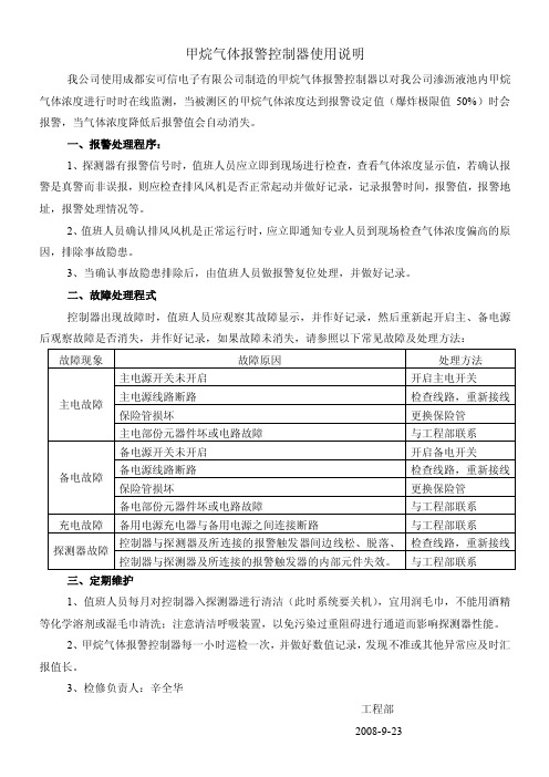
我公司使用成都安可信电子有限公司制造的甲烷气体报警控制器以对我公司渗沥液池内甲烷气体浓度进行时时在线监测,当被测区的甲烷气体浓度达到报警设定值(爆炸极限值50%)时会报警,当气体浓度降低后报警值会自动消失。
一、报警处理程序:
1、探测器有报警信号时,值班人员应立即到现场进行检查,查看气体浓度显示值,若确认报警是真警而非误报,则应检查排风风机是否正常起动并做好记录,记录报警时间,报警值,报警地址,报警处理情况等。
2、值班人员确认排风风机是正常运行时,应立即通知专业人员到现场检查气体浓度偏高的原因,排除事故隐患。
3、当确认事故隐患排除后,由值班人员做报警复位处理,并做好记录。
二、故障处理程式
控制器出现故障时,值班人员应观察其故障显示,并作好记录,然后重新起开启主、备电源后观察故障是否消失,并作好记录,如果故障未消失,请参照以下常见故障及处理方法:
三、定期维护
1、值班人员每月对控制器入探测器进行清洁(此时系统要关机),宜用润毛巾,不能用酒精等化学溶剂或湿毛巾清洗;注意清洁呼吸装置,以免污染过重阻碍进行通道而影响探测器性能。
2、甲烷气体报警控制器每一小时巡检一次,并做好数值记录,发现不准或其他异常应及时汇报值长。
3、检修负责人:辛全华
工程部
2008-9-23。
AZJ-2000甲烷检测报警仪(便携仪)使用说明书
IS09001:2000认证企业AZJ-2000型甲烷检测报警仪产品使用说明书感谢您选购本产品!为了保证安全并获得最佳效能,在安装、使用产品前,请详细阅读本使用说明书并妥善保管,以备今后参考。
前言本说明书详细地介绍了AZJ-2000型甲烷检测报警仪的使用方法及注意事项,使用者在使用前请务必仔细阅读。
AZJ-2000型甲烷检测报警仪在生产过程中执行的是国家质量技术监督局发布的国家标准:GB 13486-2000。
l概述AZJ-2000型甲烷检测报警仪(以下简称报警仪)是一种以热催化敏感元件为探头、智能单片机及多功能外围电路为核心的智能化、数字化矿用便携式安全检测仪表。
1.1产品特点1.1.1报警点在(0.50%。
2.00%)CH.范围内任意可调。
1.1.2具有整机电池电压、报警点显示功能。
1.1.3具有电源保护功能:当电池电压低于3.3V时,报警仪将长鸣10秒钟,,并在10秒钟后自动关机1.1.4报警仪配有专用的充电器:使用时只需接好电源,然后将报警仪插人充电器充电器即会自动给报警仪充电。
充电完成后,充电器将自动指示仪器充满。
1.1.5报警仪性能可靠,结构合理,操作方便,一次可连续工作12小时以上。
1.2主要用途及适用范围1.2.1主要用途用于连续监测煤矿井下各工作场所甲烷气体浓度。
1.2.2适用范围:煤矿、隧道及各种地下工程。
123适用人员:适合于煤矿管理干部、安全监察人员、通风管理人员、机电维修人员及井下流动作业人员。
1.3品种、规格1.3.1品种;煤矿井下安全检测仪表。
1.3.2规格:低浓度甲烷检测(O一5.OO%)CH4及声光报警检测范围(0.50%一2.00 %) CH4。
1.3.3型号:AZJ-2000型。
1.4型号的组成及其代表意义1.5使用环境条件1.5.1工作温度:O℃一+40C;1.5.2相对湿度:≤98 %;1.5.3大气压力:80kPa.llOkPa;1.5.4空气中的H2S:<6ppm;1.5.5风速:0 m/s一8m/s;1.5.6机械环境:无显著震动和冲击的场合;1.5.7可用在有瓦斯(甲烷)和煤尘存在的场所。
便携式甲烷报警仪使用管理与维修操作规程模版
便携式甲烷报警仪使用管理与维修操作规程模版一、概述便携式甲烷报警仪是一种用于检测甲烷气体浓度并发出警报的便携式设备。
本规程旨在规范便携式甲烷报警仪的使用、管理和维修操作,确保其正常工作和安全使用。
本规程适用于所有使用便携式甲烷报警仪的工作人员。
二、使用规程1. 使用前准备(1)在使用便携式甲烷报警仪之前,工作人员应先穿戴好个人防护装备,包括防护眼镜、防护口罩、防护手套等。
(2)检查便携式甲烷报警仪的外观是否完好,无损坏和松动等现象。
(3)确保便携式甲烷报警仪已充电或安装好电池,并处于正常工作状态。
(4)检查便携式甲烷报警仪的气体传感器是否完好,并进行相应的校准。
2. 使用方法(1)打开便携式甲烷报警仪的电源开关,待其启动后,设备开始自检。
(2)如果设备自检通过,便携式甲烷报警仪进入正常工作状态。
(3)将便携式甲烷报警仪靠近可能存在甲烷泄漏的区域,将其传感器暴露在空气中。
(4)等待几秒钟,便携式甲烷报警仪将显示当前环境中甲烷气体的浓度。
(5)当甲烷气体浓度超过预设的警戒值时,便携式甲烷报警仪将发出警报声,并同时显示高浓度警告。
3. 注意事项(1)在使用便携式甲烷报警仪时,应保持设备的传感器和气体泄漏源之间的距离不少于30厘米。
(2)当便携式甲烷报警仪发出警报时,工作人员应立即采取安全措施,迅速撤离现场,并及时报告相关人员。
(3)不得私自对便携式甲烷报警仪进行修理、改装或更换零件,如有需要,请将设备送至指定的维修点进行维修。
(4)严禁将便携式甲烷报警仪暴露在阳光下或高温环境中,以免影响设备的正常工作。
(5)在平时不使用便携式甲烷报警仪时,应将其存放在干燥、通风的地方,避免受潮或受损。
三、管理规程1. 借用记录(1)每次借用便携式甲烷报警仪,应填写借用记录,包括日期、借用人员、使用地点等信息。
(2)借用人员在借用时应对便携式甲烷报警仪进行检查,确保设备完好并处于正常工作状态。
(3)归还时,借用人员应在借用记录上签字确认,归还后由负责人核对设备的完整性,并签字确认。
- 1、下载文档前请自行甄别文档内容的完整性,平台不提供额外的编辑、内容补充、找答案等附加服务。
- 2、"仅部分预览"的文档,不可在线预览部分如存在完整性等问题,可反馈申请退款(可完整预览的文档不适用该条件!)。
- 3、如文档侵犯您的权益,请联系客服反馈,我们会尽快为您处理(人工客服工作时间:9:00-18:30)。
深圳东日瀛能科技有限公司有毒有害智能气体变送器产品说明书深圳东日瀛能科技有限公司目录1、概况-------------------------------------------------------------------------------22、技术特点-------------------------------------------------------------------------23、技术参数-------------------------------------------------------------------------34、外形尺寸及安装方式----------------------------------------------------------44.1安装位置--------------------------------------------------------------------54.2安装方法--------------------------------------------------------------------55、电气连接-------------------------------------------------------------------------66、负载特性--------------------------------------------------------------------------77、操作说明--------------------------------------------------------------------------87.1LCD显示说明---------------------------------------------------------------87.2按键操作说明---------------------------------------------------------------817.3变送器设置------------------------------------------------------------------98、设备维护--------------------------------------------------------------------------159、注意事项--------------------------------------------------------------------------1510、检测气体一览表----------------------------------------------------------------161.概述固定式气体变送器通过对大气中氧气、可燃气体、有毒有害气体进行连续在线检测及声光报警,不仅对特殊场合气体浓度起到控制作用,对危险现场气体泄漏更有预警作用,及时保护各种现场的生命以及财产安全。
检测仪采用进口传感器结合高速、高精度处理电路,具有信号稳定,精度高、重复性好等优点,并且采用防爆设计,适用于各种危险场合。
仪器输出各种标准信号,可以兼容各种报警系统、PLC、DCS等控制系统。
仪器广泛应用于石油、化工、冶金、消防、煤矿、电力、船舶、环保、电信、医疗等行业。
2.技术特点采用高速、高精度处理电路,实现仪器测量的快速和准确三线制4-20mA信号和RS485数字信号输出,可实时与计算机进行通讯2深圳东日瀛能科技有限公司即插即用国际标准智能化传感器,现场维护非常方便独特的LCD带背光设计技术,现场设备的观察、维护不再受光线变化的困扰全量程范围的温度数字补偿软件或按键实现变送器在现场自由组态,如查看、设定、校准本安电路及防爆外壳设计,现场维护安全、方便、快捷3.技术参数壳体材料:铝合金隔爆外壳外型尺寸:125X94X199隔爆等级:Ex d IIC T6防护等级:IP66整机重量:1.8Kg精度:±3%F.S.LCD显示内容:5位8段数码显示测量值,8位16段米字型信息提示LCD显示模式:ppm、%VOL,%LEL工作环境温度:-20~50℃工作环境湿度:10~95%RH非凝露3模拟信号输出:三线制4-20mA线性输出数字信号输出:标准RS485信号输出,配合Moden及通讯软件可与计算机进行通讯工作电压:24VDC(12~30VDC)基本工作电流:11mA@24V(毒气和氧气),33mA@24V(催化燃烧、红外传感器)本安等级:Exd II CT64.外型尺寸及安装方式4深圳东日瀛能科技有限公司单位:mm4.1安装位置根据气体的比重及风向,变送器应安装在离气体可能泄漏地点处一米范围内,这样变送器的实际反应速度比较快,否则,有可能出现变送器安装处可燃气体或有毒有害气体浓度不超标,而泄漏点处局部气体已经超标,变送器和主机却不能报警的现象。
变送器安装距地面高度应大于30厘米以防有水溅入。
一般情况下,检测比重小于空气的有害气体,探头应安装于房屋或设备的上方;比重大于空气的有害气体,探头应装于贴近地面处。
变送器安装探头应朝下,如在户外安装应在变送器上方加装遮雨板。
5注意:开放区域每一探头的检测范围为100平方米,同时还要考虑气体扩散、风向、温度、湿度及区域封闭性等因素。
安装时还应考虑防尘防水和防高温等保护措施。
4.2安装方法用户可以自行设计固定方式。
但是要注意保持探头的传感器面和地面垂直。
探头固定后,将壳体上盖螺钉卸下,把屏蔽(三芯3×1.5mm)传输电缆从过线通道插入。
建议使用屏蔽软芯(三芯3×1.5mm)电缆,将电缆接于端子位置。
检查接线牢固后,固定电缆和壳体上盖。
5.电气连接电气定义如图5.1所示。
6深圳东日瀛能科技有限公司图5.1仪器输入:24V(供电电源功率2.4W以上)仪器输出:RS485,4-20mA,继电器(声光报警可选)接线方式及定义见电气连接图6.负载特性7输出信号:4-20mA负载阻抗R与电源V的关系为:R≤50(V-12)7.操作说明8深圳东日瀛能科技有限公司变送器一旦接通电源(12~30VDC)开始工作,LCD显示屏背光被点亮,信号强制输出4mA。
变送器显示测量量程。
如右图所示。
图7.17.1LCD显示说明LCD显示按照操作需求分为两部分:测量信息设置信息测量信息显示仪器检测对象,当前浓度,显示单位。
如右图7.2所示。
当前检测气体为一氧化碳(CO),0.0ppm。
图7.2设置信息显示仪器量程、零点漂移等信息;具体详见7.2;7.2按键操作说明仪器总共3个按键,分别为M(设置键)、+(增加键)、—(减少键);位置如下图7.3所示。
9图7.3进入菜单:测量状态下,按下M键5S以上,进入设置状态菜单定义:CAL、LSE、CSE、HSE、ALE、AHE、AHAL、SAVE 按键加速:长按+、—按键具有加速功能7.3变送器设置显示变送器量程功能:显示变送器测量量程显示:CAL菜单、仪器满量程;如右图7.4所示。
图7.410深圳东日瀛能科技有限公司操作方法:在测量状态,按下‘M’键5秒以上,则进入设置状态,显示变送器的设定量程,再次按下设置键,则进入变送器调零功能。
变送器调零功能:变送器调零显示:LSE菜单、当前零点漂移值;如右图7.5所示。
图7.5操作方法:将变送器放在空气中(注意:如果有被测气体存在,则调零后会将目前的浓度定为零点)。
同时按住+、—按键3秒以上,此时LCD背光灯闪烁,则调零完成,并退出设定状态。
进入下一菜单CSE。
标定气体浓度设置功能:设定校准气体的浓度值。
显示:CSE菜单,设定校准气体浓度值;如右图7.6所示图7.6操作方法:使用‘+’与‘—’按键,使LCD显示为当前标定气体的浓度值,同时按下‘+’和‘—’按键,则完成标定气体浓度设定,进入11下校准功能。
如果不需要修改标准气体浓度值时,按下M键,则可进入标定设置。
变送器标定功能:变送器标定显示:HSE菜单,当前测量值;如右图7.7所示操作方法:给变送器通入标准气图7.7体(如:350PPM),待显示稳定后,同时按下‘+’与‘—’按键3秒以上,此时LCD背光闪烁,则标定完成。
如需退出标定状态,需按下‘M’按键。
图7.8为变送器标定示意图,操作方法如下:标定说明:将已知的标准气体,通过流量计控制在200—300ml/min,再通过导管与标气罩连接,将标气罩罩在变送器探头上通气,输出稳定后,依照“变送器标定方法”操作使主机的显示值与标准气体标称值相同,然后关掉气体。
观察能否回到零点(在纯净空气环境中)或起始点,然后再重复一次,两次数值相差较小(在基本误差范围内)标定即可结束。
相差很大(3%以上)则需重复以上12深圳东日瀛能科技有限公司方法标定直至符合要求。
图7.8恢复出厂设置(误操作下使用)功能:恢复出厂设置显示:CSE菜单,恢复数据密码。
如图7.9所示图7.9操作方法:使用‘+’与‘—’按键,使LCD显示恢复设置代码1101。
13按住‘M’键10秒以上,此时LCD背光闪烁,并进入HSE菜单。
仪器恢复出厂设置。
仪器满量程修改功能:修改仪器满量程,即20mA对应浓度值。
显示:CAL菜单,仪器满量程。
操作方法:在CSE菜单下,使用‘+’与‘—’按键,使LCD显示代码1104。
按下‘M’按键,显示画面图7.10跳至CAL菜单画面,如图7.4所示。
使用‘+’与‘—’按键,将量程示值调至目标值,按‘M’按键,画面跳至密码输入页面,如图7.10所示,输入保存密码“158“,长按‘M’按键直至背光闪烁,满量程修改完成。
报警点设置功能:修改仪器报警点显示:ALE、AHE、AHAL菜单,报警点。
操作方法:图7.1114深圳东日瀛能科技有限公司1)修改第一报警点在测量状态下,同时按下‘+’与‘-’按键,此时屏幕提示AL,即进入第一报警点设置。
如图7.11所示。
使用‘+’‘-’按键调节第一报警点,此数值即为继电器动作点。
2)修改第二报警点第一报警点设置完毕,按‘M’按键一次,进入第二报警点设置,如图7.12所示。
该报警点高于下限报警点。
(该功能不对继电图7.12器进行动作,为预留功能)3)设定报警回差在AH画面,按‘M’按键一次,LCD显示画面跳进AHAL界面。
如图7.13所示。
用户可根据需求输入适当数值,也可输入0。
图7.134)报警点保存输入回差值后,按住‘M’按键。
15屏幕左下方会显示SAVE,输入密码‘3’之后,如图7.14。
持续按‘M’按键,直至背光闪烁,系统自动退图7.14出到工作状态,报警点保存完成。