Makerware简易使用手册
【一键搞定软包建模】3DMAX面包机插件BreadMaker使用教程
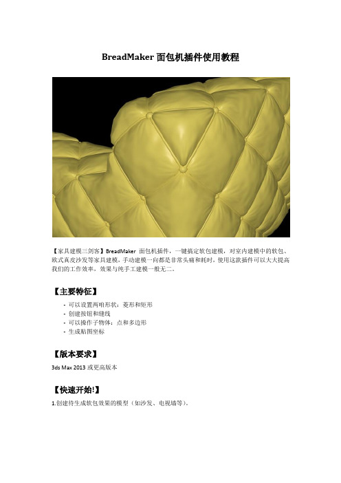
BreadMaker面包机插件使用教程【家具建模三剑客】BreadMaker面包机插件,一键搞定软包建模,对室内建模中的软包、欧式真皮沙发等家具建模,手动建模一向都是非常头痛和耗时,使用这款插件可以大大提高我们的工作效率,效果与纯手工建模一般无二。
【主要特征】- 可以设置两咱形状:菱形和矩形- 创建按钮和缝线- 可以操作子物体:点和多边形- 生成贴图坐标【版本要求】3ds Max 2013或更高版本【快速开始!】1.创建待生成软包效果的模型(如沙发、电视墙等)。
2.打开BreadMaker面包机插件。
方法有两种:- 直接拖动BreadMaker脚本文件到3dMax窗口。
- 点击3dMax主菜单–脚本–运行脚本,选择BreadMaker脚本,点击“打开”按钮打开BreadMaker窗口面板。
【BreadMaker界面】3.设置参数。
(后面附录“参数详解”)4.点击“生成”按钮生成。
【参数设置效果图】【压力设置效果图】【编辑钮扣】钮扣是一组实例化的半球,编辑钮扣就是编辑实例中的任一个半球。
1.选择任一个“钮扣”对象,切换到修改面板,可以通过修改球体参数来修改“钮扣”,比如修改控制大小的“半径”参数:【修改球体半径】2.也可以给“钮扣”应用“编辑多边形”修改器,切换到子物体,编辑“钮扣”的形状、位置、大小等。
【沿Z轴向外移动球体顶点】【编辑球体形状】【编辑缝线】缝线是一组可渲染样条线,编辑缝线就是编辑样条线。
选择缝线对象,切换到修改面板。
通过修改样条线参数来修改缝线。
【修改“厚度”参数来设置缝线粗细】【按选择的“点”生成】1.编辑多边形,切换到“点”子物体,选择一些点(一般按棋盘格布局选择)。
2.应用readMaker插件,勾选“点”选项生成。
【按选择的“面”生成】1.编辑多边形,切换到“多边形”子物体,选择一些面。
2. 应用readMaker插件,勾选“多边形”选项生成。
附:参数说明创建方法:-菱形、矩形:生成软包单元格的形状。
威尔克姆简明教程.doc

威尔克姆制版软件简明教程第一节电脑绣花制版基本知识1、花样编辑器和花样浏览器:威尔克姆软件包由花样编辑器和花样浏览器组成;花样编辑器即制版软件,它是电脑绣花制版和设计的主程序,它可以设计、编辑和修改花型,并将已设计好的花型输入到绣花磁盘上,在桌面上的图标为花样浏览器是编辑器的一个辅助程序,在桌面上的图标为它专用于查看和管理已设计好的EMB格式的花形,并可进行一些简单的辅助性操作,如通过双击EMB格式的花型图象可直接打开文件、格式化磁盘、删除、复制花样、将花样文件转换到绣花磁盘上等。
要运行浏览器,必须先打开花样编辑器;读者要注意,花样浏览器不能直接查看 DST或DSB等电脑绣花机可读入的文件,这些类型的文件可由富怡花样管理软件来查看。
2、花样文件格式和绣花磁盘文件格式通常情况下,不论是什么制版软件,它所设计出来的花型都是以一种电脑绣花机不能直接读出的文件格式保存下来的,然后再转换成电脑绣花能读出的格式。
例如:DOS版本的田岛软件所生成的花型设计文件格式为*.ESD,Windows版本的田岛软件所成的花样文件格式为*.EMB,Windows版本的威尔克姆软件所成的花样文件格式为*.EMB ,DOS版本的天木软件所生成的花样文件格式为*.ndp等;这些格式的文件电脑绣花机都不能直接使用,必须转换成*.DST(田岛绣花机三进制格式)或*.DSB(百灵达二进制格式),电脑绣花机才能读进内存进行绣花。
为什么制版软件所生成的花型设计文件(EMB格式)绣花机不能读进呢?这是因花样设计文件实际上是一种特殊的格式的图形文件,它含有图象信息(如图形大小、色彩、相对位置等信息)和制版编辑信息(如选用的针迹类型和密度等信息),而绣花机只能读DST(三进制)或DSB(二进制)格式的针位文件,因为绣花机的步进电机X轴和Y轴的位移尺寸(最低偏移量为0.1mm)以及停止、换色、剪线等控制信息只能用二进制或三进制来编码。
由此可见,DST或DSB格式的文件是由EMB文件经过滤除去制版信息转换而来的。
西通电子有限公司桌面型3D打印机使用手册说明书
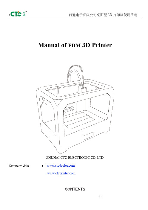
Manual of FDM 3D PrinterZHUHAI CTC ELECTRONIC CO, LTD Company Links:CONTENTS1. CONTENTS………………………………………………………..Description Matters…………………………………………………Manual Introduction………………………………………………Precautions ………………………………………………………Safety Precautions……………………………………………………Contact us……………………………………………………Accessories List………………………………………………….2. Product Description………………………………………………………………Product Categories………………………………………………………Appearance………………………………………………………….Product Specifications………………………………………………………….Technical parameters……………………………………………………Environmental Specifications……………………………………………………3.Instructions……………………………………………………………….Prepare for printing……………………………………………..Computer preparations………………………………………………….Replicatorg installment………………………………..Software Functions……………………………………………..Makerware installment (compatible with this software)……………Software Function………………………………………………LCD screen function keys and the Key Functions comment…………………………….4.Take the model…………………………………………………………………5.Maintenance……………………………………………………………………Clean the printhead………………………………………………………Tighten belts…………………………………………………………Screw axis and Maintenance…………………………………………………6.Troubleshooting………………………………………………………………7.Warranty statements and license agreement………………………………………………8.Operations Guide………………………………………………………………Let’s go1.Instructions mattersManual IntroductionThis User's Guide includes product description, operating instructions, print a test model, consisting of maintenance and troubleshooting, and several other parts. Please read it carefully, and use the3D printer based on the contents of the specification.PrecautionsThis product is due to the different regions from each customer, and the voltage of each region are different, so please make sure how much voltage before you use the printer in your area (generally 110v and 230v)This product required the customer's printer maintenance after using a period of time, it can extend the life of the printer with regular proper maintenance.Safety PrecautionsOur company do not recommend using other brands of supplies, in order to get the 3D best printing results, please use our special supplies. If use other supplies caused by maintenance and repair, its not included in our company's warranty.When the printer is printing or just finished printing , please do not touch the rest of the model, the head of printer and the platform or the internal body due to the high temperature .Contact UsIf you need to contact the after-sale 3D printers service, you can add my company’s group number "102304634" directly SD card user guide : about 3D printers use and troubleshooting information, available on the instruction included, you also can add my company's 3D printing community (group no. "102304634") for online technical support.You can add my company's sina weibo, it always update my company's new technology and software upgrades, add sina weibo have access to random rewards and prizes "a tablets "go into the sina weibo search CTC 3D printing in the future "concern" and “reprinted”can get more opportunity and higher rewarded .Accessories Listnumber the name of material quantity unit1 3D printer 1 table2 power line 1 root3 USB cable 1 root4 toolkit 1 cover5 SD卡 1 piece6 printing supplies 1 volume7 hanging material column 2 slipProduct CategoryProduct Categories3D printing is based on the west fuse deposition manufacturing process (FDM) rapid prototyping device that connected to the computer via an SD card online or print spooling, only an ordinary computer can be completed via USB cable to print, as long as you there have STL 3D file format you can complete a variety of print job complex three-dimensional solid model. This device is easy to use, even if you have never used 3D printer, but you can easily print all kinds of 3D models through 3D printer.Appearance(three Generation)(one Generation)(two Generation)Product SpecificationsThe total volume of printer:320*467*381mmPackage Size:565*430*535mmWeight (with packaging):15KGConstruction size:225*145*150mmInput voltage : 220VPower Requirement:210VConstruct platform temperature: about110(adequate heating in winter,appropriate cooling in summer)Nozzle extrusion flow rate is about 24cc / hrSupported operating systems:Windows XP Windows7/8(32位/64位)Software:ReplicatorG 或西通汉化版(Software is compatible with MakerWare)Print materials:ABS ,PLAMaterial properties: 3D printing special ABS and PLA(only produced in our company)Layer precision:0.1mm-0.5mm Positioning Precision:XY axis 0.011mm Filament Diameter:Z axis 0.0025mm Nozzle diameter:0.4mmMovement shaft speed:30mm/s_100mm/sRecommended nozzle movement speed: 35-40 mm/sInput file types:stl , gcodeRecommended environmentOperation environment :Installed in a well-ventilated, dust-free area. Temperature: 15 ° C to 35 ° C. Humidity: 20-80% (non-condensing)Storage environment : Temperature: 0 ° C to 40 ° C . Humidity: 10-80% (non-condensing). The existence of non-corrosive gases and cleaning applications.3.InstructionsPrepare for printing(1) Check whether the appearance of 3D printers outside the box bumps scratches and other defects.Check the box edges and corners are squeezed or without deformation or rupture of the place.(2)Open the box, after subtracting out the printer nozzle fixed tie, (tied in the front left side of the Z-axis X-axis Y-axis.Use Water-nose pliers to cut straps fixed printhead.(3)open the print head surface foam (Note: Try not to use face of the knife in order to avoid the above print head cable was hung before to hung up now)take the print head is mounted on the X-axis bracket, mounting orientation shown in rather the two screws.(图一)(图二)(4)Taking out the tube hanging material feeding tube installed in the hole at the back of the printer, and put the printing supplies into the feeding tube hanging, then pull out the printing supplies, printing supplies section of the circle into the print head party hole (Note use the left print head is inserted left and use the right print head is inserted on the right)(5) Check Limit switches cable of the printer loose or fall off the surface.(Z-axis ) (Y-axis ) (X-axis )(6)Check whether the voltage can reach the printer of voltage required (110 v or 220v, where the power supply is determined on the printer)(7)Taking out the SD card to read inside of the printer driver and installing the driver.(8)Turn on the printer and manipulate to control panel , make Z axis up to the top of the printer, check the printer nozzle parts and print platform’s distance can meets the criteria (best distance test method: Put a sheet of A4 paper in the printing surface of the platform and control panel make it go to the top of the Z-axis, and then pull the A4 paper, printing paper can be pulled out, but with a little bit of strength, but the paper will not be scratched,) Note: The blue paper of print platform surface can not be teared. Otherwise it will affect the print quality(9)You need to be ready for STL file format, after the software has been installed in the printer top can open the file, adjust the parameters, you can start printing3.1 Preparations for computer3.1.1 Installing Replicatorg drive software(1)Taking out SD card to read inside of the printer driver, looking for 3dsetup folder(2)Open 3dsetup file folders and looking for software(3)Right-click the file to open the software into the software installation manager(4)Click Replicatorg software installation (you can choose to install English, Chinese also can choose )(5)Click Replicatorg software automatically installs the icon will appear and then click the Next button.(6)Click Next will appear one icon, click on the Install button、(7)Click the Install button will pop up a window, need to wait for moments(8)After Click the Install button in the process the computer will pop up dialog box, please click Next(9)After clicking Next the computer will appear fifth consecutive prompt, click "Install this driver software."(10)Click Five times"Install this driver software" button to complete the installation , at the same time the computer will pop up dialog box to view the program was successful (query methods: View pop-up dialog box Driver Name, all check mark indicates that the software is installed successfully, if X number or ! number will be deemed not to have been successfully installed), after checking please click "Finish."(11) Click Finish emperor of the page "Next" button to begin the lights, the left the mouse click "Next" button, the computer Replicatorg print software installation completed.3.2.2 Software Functions(1) Charging the machine, link USB, open replicator, (first double nozzle to choose The Replicator Dual machine, choose the first single nozzle The Replicator Single)(2) Next is to select the correct serial port (Please note the serial number of the machine is often not com1)(3) Click online.(4)Then select the file you want to printThen there will be a pattern file:(5)Open the Control PanelSet the nozzle temperature: Target Tempriture box set a carriage.Different machines due to differences in temperature conductivity, temperature difference is relatively large, its better to start from 215 degrees , try to use the wire. The temperature rises rapidly to reach 190 degrees, indicating a larger margin heating. If relatively slow, indicating a small heating. If the Szymborska appear, there may bot be enough temperature. If there are bubbles silk sound, temperature high. From low to high, according to the actual situation to set a suitable temperature. If you click on the reverse, the extrusion head motor reversal,l running out of the material is sent back . Cut flat new material, take them into the hole , click stop, then click forward, the motor is transferred out of the head, insert a little tight, the material is bite into the nozzle, until spinning. Please note, it will arrive at a predetermined value will continue to wait for the temperature down when he reaches the bottom surface of the print.How to start printing:The map is moved to the appropriate location, click the following buttonChoose:Please note that the above options, click Generate Gcode to be Gcode. After generating gcode, this time move the print head to the center position,Can modify Feedrate (mm / s) to 20, Tralvel Feedrate 20 can make more accurate printing. How to calibrate (normal calibration is not necessary):Through the control panel take the head to the platform。
schema maker使用说明
schema maker使用说明Schema Maker使用说明1. 简介Schema Maker是一个用于创建结构化数据(schema)的工具。
结构化数据是一种描述网页内容的标记语言,可以帮助搜索引擎更好地理解和展示网页内容。
2. 安装和启动安装在终端中执行以下命令来安装Schema Maker:npm install -g schema-maker启动在终端中执行以下命令来启动Schema Maker:schema-maker3. 创建Schema新建Schema启动Schema Maker后,点击”New Schema”按钮创建一个新的Schema。
在新建的Schema中,点击”+ Add Property”按钮来添加属性。
属性包括属性名、属性类型、描述等内容。
添加子属性在属性中,点击”+ Add Sub-property”按钮来为属性添加子属性。
4. 生成代码选择生成代码类型点击”Generate”按钮后,选择要生成的代码类型,目前支持JSON-LD和Microdata两种类型。
生成代码选择完代码类型后,点击”Generate Code”按钮即可生成代码。
5. 导出代码复制代码生成的代码会显示在界面上,可以直接选中代码并复制。
保存为文件点击”Export”按钮,选择保存为文件,即可将生成的代码导出为指定的文件。
以下是一个使用Schema Maker创建的简单Schema示例:•Property 1:–Name: property1–Type: Text–Description: This is property 1•Property 2:–Name: property2–Type: Number–Description: This is property 2–Sub-properties:•Sub-property 1:–Name: subProperty1–Type: URL–Description: This is sub-property 1 7. 注意事项•请确保属性名、属性类型等信息的准确性。
Makerbot 3D打印机使用手册

Makerbot打印机基本使用手册使用前需要注意: 1.文件名不能为中文,并且文件名字符最好不超过30字符;2.模型必须为密封无缝无破面,模型内部干净无重面;3.模型三角面数最好不超过一百万个;4.模型细节最好不小于1mm。
一、Makerbot2/2X打印机物理按钮的操作指示介绍: M 字按钮的操作指示:为确认和调出菜单选项的命令;左箭头按钮的操作指示:为返回和取消任务的命令;右箭头按钮的操作指示:为进入下一层操作的命令;上箭头按钮的操作指示:为向上移动的命令;下箭头按钮的操作指示:为向下移动的命令。
二、Makerbot 2/2X 主次页展开操作命令树: 1、BuildfromSD从SD卡中选择构建(按M键进入并通过上下箭头选择程序后按M键确认打印)2、Preheat预热2-1startpreheat开始预热ExtruderON挤出机正在进行中☆2X预热RExtruderON挤出机正在进行中LExtruderOFF挤出机正在进行中Platform OFF 水平构建底板取消3、Utilities 实用工具3-1Monitormode监控模式3-2ChangeFilament更换材料Load进丝Unload退丝☆2X退换丝Loadright右边进丝Unloadright右边退丝Loadleft左边进丝Unloadleft右边进丝 3-4 LevelBuildplate 水平构建底板矫正(此操作命令,需要准备一张0.1-0.2mm厚度的纸,当启动水平矫正命令时,将纸片放置于构建底板与喷头之间,然后按M键读取显示屏信息一直到喷头开始移动,这个时候,我们可以通过旋钮调整水平构建板底部的三个螺丝来达到喷头与底板的间隙均匀,间隙大概有0.2-0.3mm即可,详见附录图目一)3-5HomeAxes回归初始轴(此命令的要点在于运行后,打印机喷头会向右后方移动,并且水平底板会向上抬高,就是预备打印的状态。
此命令的中,需要水平底板在休息状态时,必须借助Runstartupscript命令调整Z轴来实现)3-6 JobMode 工作模式(此命令主要是在于手动调节X轴、Y轴和Z轴的位置)3-7Runstartupscript运行启动脚本(第一次启动打印机时使用,目的在于调整机器到最佳打印状态)3-8Enablesteppers/DisableSteppers启用/禁用电步机3-9 Blink LEDs 调整LED灯Exitmenu 4、Infoandsettings信息和设置4-1Botstatistics构建统计4-2GeneralSettings综合设置Sound OFF 声音关闭/LEDcolorWHITE/LED灯颜色/AccelerateON加速打开/ HeatHold00m热度保持00分钟HelpTextON帮助文本打开/ToolCountON 工具计算打开HeatedPlateON 加热底板打开(2X功能)Exitmenu 4-3PreheatSettings预热设置RightTool 230 正确共设230°(指的是默认总成温度,比如预热的顶点温度)4-4VersionNumber版本信息4-5 RestoreSettings还原设置Exit menu ☆另:特别需要注意的是,我们在打印过程的中,难免会出现各种各样不可预知的问题。
makerware软件操作教程
makerware软件操作教程
大家都知道现在3D打印机很火热,
今天我就和大家一起来学习使用Windows版makerware的软件操作,并利用点构的3D打印机以win7系统为例:
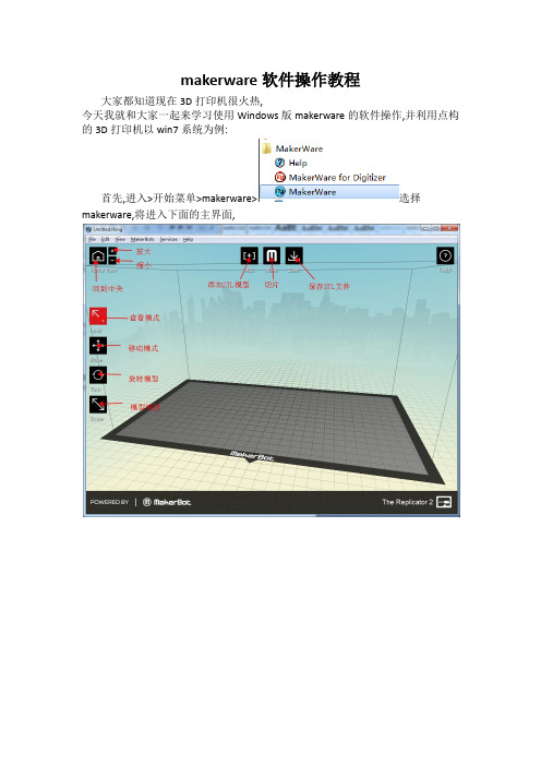
首先,进入>开始菜单>makerware>选择makerware,将进入下面的主界面,
第二步,调整好模型大小\方向等参数后,点击按钮后进行切片操作,
选择好耗材类型\打印精度等参数后就可以点击下方的按钮进行切片了, 如果勾选了将会出现下面的预览界面
点击保存gcode
最后,将保存好的GCODE文件传入内存卡中,插入变形金刚3D打印机中,选择你刚保存的文件,这样你想要的作品就完成了。
X-MAKER 3D打印机用户使用手册说明书
用户使用手册目录我们的产品3D打印机通电开机开机配置安装料架安装耗材屏幕功能进料操作退料操作模型打印打印完成拆除支撑换料操作移动校准&调平常用设置产品组成包装清单3D打印机结构X-MAKER App软件下载软件介绍万物 / 主题 / 设计打印010419X-PRINT 3D打印机基本参数软件下载界面概览模型编辑切片设置模型打印2530注意事项31帮助与支持32常见问题和解决方案33我们的产品产品组成X-PRINT切片软件X-MAKER 3D打印机X-MAKER设计App柔性磁吸底板×1U盘×1快速指导手册×1电源线×1工具钳×1工具袋×1内置可直接打印的创意模型配套App X-MAKER 安装包切片软件X-PRINT安装包PLA耗材×1料架×13D打印机×1包装清单3D打印机结构主机箱电源开关电源接口外装饰灯喷头套件USB接口料架位置耗材入口挡板柔性磁吸底板打印平台外装饰灯触摸屏材料挤出机断料检测取出电源连接线,连接打印机和电源插座,如上图所示(*接电时请保持手部干燥)开机按下开关按钮,即可启动打印机通电3D打印机通电开机根据需求,选择合适的语言;也可以在“设置”>“语言”里面重新配置WIFI连接: 同一局域网内,通过APP搜索机器连接热点连接: 没有网络的情况下,将机器作为连接热点打印机通电后,打印屏启动,根据提示可以对3D打印机进行简单的设置。
选择语言连接方式放置耗材安装料架将料架配件安装在X-MAKER 主机上,放置打印耗材将耗材整理好,挂在料架装置上(*注意耗材不要出现打结和穿插的现象)耗材入口正确悬挂方式耗材入口错误悬挂方式送材料进入导料管约3-5cm。
为了使材料能顺利进入,需向上推动弹簧(如图红色箭头位置)安装方式注意:为了方便进丝,耗材的首端需捋直并剪成斜角耗材入口打印:选择打印文件连接:打印机连接方式 (WIFI/热点)设置:更多其他设置换料:智能进料/退料功能预热:喷头和热床升温降温 挤出:手动进料和退料校准:调整喷头和底板间隙移动:对X、Y、Z轴进行移动语言:切换各种语言控制:灯光、风扇、断电续打等开关帮助:更多信息入口状态:打印机状态关于:打印机相关信息首页设置换料: 进入换料界面,选择进料,进入对应的界面,喷头自动开始升温,达到目标温度,喷头自动进料,看到喷嘴有材料挤出,即可点击取消进料,也可以等待自动进料完成。
Makerware简易使用手册
保存文件
另存为
生成s3g文件
联机打印(暂不支持)
连接数据库打印(暂不支持)
2.Edit/编辑(后为快捷键):
后退一步
复原一步
剪切模型
复制模型
粘贴模型
原地复制模型
删除
全选模型
取消全选
所有模型自动布局
设置
3.View/视图(后为快捷键):
回归3/4视角
顶视图视角
侧视图视角
前视图视角
透视视角模式(建议选择)
快捷帮助
联网获取帮助
关于软件版本
软件基础界面一定要熟练掌握,其他功能平时使用不多,熟悉即可。
操作详解(以更复杂的双喷头做范例)
将模型拖动至软件界面中或者点击Add打开模型。
注:1.模型路径需要是全英文路径,模型文件名称也要使用英文标识。
2.兼容模型格式:Stl和Obj)
模型可通过左侧使用栏来调整位置、大小以及打印使用喷头。
题前文
Makerware相较于ReplicatorG软件界面设计更加美观、软件优化更加完善、键位设计更加合理,故使用上流畅很多,转码速度也较ReplicatorG更加迅速、稳定。
软件使用
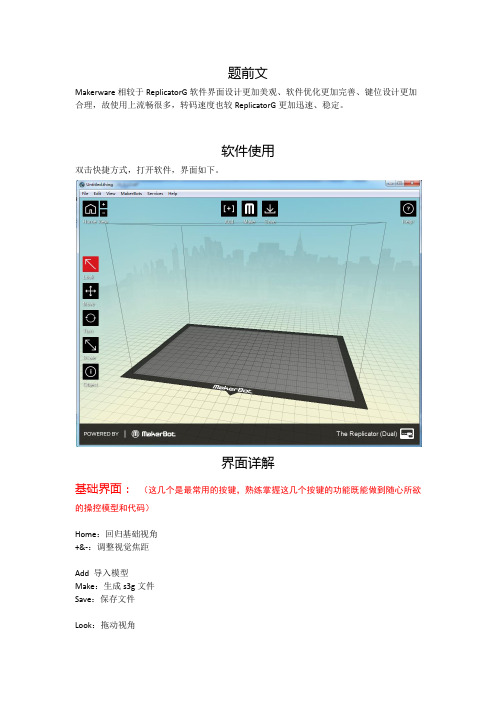
双击快捷方式,打开软件,界面如下。
界面详解
基础界面:(这几个是最常用的按键,熟练掌握这几个按键的功能既能做到随心所欲的操控模型和代码)
Extruders喷嘴温度
Bulid Plate底板温度
常用材料温度设置
打印速度设置
Speed打印速度:
Speed while Extruding打印速度建议40mm/s
Speed while Traveling空走速度建议70mm/s
最后点击Export生成s3g代码或者x3g代码进行脱机打印。
ledmaker软件应用仿单v3.0[宝典]
![ledmaker软件应用仿单v3.0[宝典]](https://img.taocdn.com/s3/m/5fe696cfcf2f0066f5335a8102d276a2002960aa.png)
LedMaker软件使用说明书(V3.0)北京精信达安科技有限公司目录LedMaker软件使用说明书 (1)第一章概述 (3)1.1 概述 (3)1.2 主要特性 (3)1.3 运行环境 (3)第二章安装与卸载 (4)第三章使用详解 (4)3.1 菜单栏 (4)3.1.1文件 (5)3.1.2屏参设置 (7)3.1.3 控件 (13)3.1.4操作 (13)3.1.4语言 (19)3.1.5帮助 (19)3.2 工具栏 (19)3.2.1创建向导 (20)3.2.2添加节目 (20)3.2.3添加模拟时钟 (21)3.2.4添加文本 (22)3.2.5添加时间 (25)3.2.6添加温度 (26)3.2.7添加计时 (27)3.2.8添加图片 (27)3.2.9删除 (28)3.3 状态栏 (28)3.4 多分区编辑 (28)3.5 文本编辑的特殊说明 (28)第四章异步控制卡说明 (29)第五章常见问题答疑 (29)第六章技术支持 (30)第一章概述1.1 概述LedMaker系统软件是一款由北京精信达安科技有限公司研发并发行的、专为本公司异步控制卡配套的操作软件,是集编辑、模拟和控制为一体的专用的LED显示屏编辑系统。
本软件对其配套的控制器的功能提供了安全、稳定及可靠的支持,因此,其控制不仅被广泛用于车站、码头、医院、银行、邮局、政府等对可靠性有严格要求的领域,而且在娱乐、餐饮、商场、高校等场所也得到了广泛应用。
本软件根据人机交互原理设计,界面简洁而不单调,功能强大而不紊乱,结构合理,层次分明,处处显示出人性化的特点,学习、使用及维护都非常方便,大大地减少了重复性劳动、提高了工作效率。
1.2 主要特性可以进行多区域和多节目同时编辑,互不影响,并且能够实时预览编辑效果;可以从串口自动检索显示屏;丰富的边框特效,并实时显示。
支持文本编辑,文字特效;支持静态、动态图片(bmp,jpg,gif等格式(V2.0版本仅支持gif的第一帧));支持数字钟、模拟时钟、农历;支持倒计时;提供节目列表,可以在同一场景依次播放不同节目,并能对各个节目设置不同的播放模式、停留时间、定时播放等;支持显示屏参数的初始化设置、保存及加载。
CityMaker Explorer V6.0用户手册
版权声明《CityMaker Explorer》版权属于北京伟景行数字城市科技有限公司所有。
任何组织和个人未经北京伟景行数字城市科技有限公司许可与授权,不得擅自复制、更改该软件的内容及其产品包装。
本软件受版权法和国际条约的保护。
如未经授权而擅自复制或传播本程序(或其中任何部分),将受到严厉的刑事及民事制裁,并将在法律许可的范围内受到最大可能的起诉!版权所有,盗版必究!(C)2001-2010 北京伟景行数字城市科技有限公司地址:北京市海淀区中关村南大街35号紫竹院公园西院北京伟景行数字城市科技有限公司邮编:100048目录引言 (1)关于本手册 (1)阅读说明 (1)第一章CityMaker Explorer介绍 (3)CityMaker Explorer介绍 (3)CityMaker Explorer新特性 (3)CityMaker产品体系 (4)CityMaker Builder (4)CityMaker Server (5)CityMaker SDK (6)第二章安装与卸载 (7)运行环境 (7)软件环境 (7)硬件环境 (7)安装CityMaker Explorer (7)卸载CityMaker Explorer (8)第三章界面说明 (13)CityMaker Explorer界面布局 (13)鼠标漫游操作 (14)键盘漫游操作 (14)第四章工程的创建与管理 (15)新建工程 (15)打开工程 (15)保存工程 (15)另存工程 (16)第五章CityMaker Explorer选项 (17)关于CityMaker Explorer选项 (17)漫游参数 (17)缓存位置 (18)软件授权 (19)第六章工程设置 (20)关于工程设置 (20)导航图设置 (20)安全 (21)第七章图层 (22)加载地形图层 (22)加载模型图层 (22)加载矢量图层 (23)矢量图层属性 (24)Style选项卡 (24)Annotations选项卡 (26)Layer选项卡 (26)第八章场景 (27)模型显示模式 (27)实体模式 (27)草图模式 (27)视图要素 (27)大气效果 (27)天气特效 (28)第九章漫游 (29)漫游模式 (29)相机控制 (29)智能比例尺 (29)全屏 (30)第十章创建二维对象 (31)文本标注 (31)创建文本标注 (31)文本标注属性 (31)图片标注 (32)创建图片标注 (32)图片标注属性 (33)多段线 (33)创建多段线 (33)多段线属性 (34)多边形 (34)创建多边形 (34)多边形属性 (35)矩形 (36)创建矩形 (36)矩形属性 (36)正多边形 (37)创建正多边形 (37)正多边形属性 (37)圆形 (38)创建圆形 (38)圆形属性 (39)椭圆 (40)创建椭圆 (40)椭圆属性 (40)圆弧 (41)创建圆弧 (41)圆弧属性 (42)二维箭头 (43)创建二维箭头 (43)二维箭头属性 (43)第十一章创建三维对象 (45)导入模型 (45)导入模型 (45)模型属性 (45)三维多边形 (46)创建三维多边形 (46)三维多边形属性 (46)长方体 (47)创建长方体 (47)长方体属性 (48)圆柱 (49)创建圆柱 (49)圆柱属性 (49)圆锥 (50)创建圆锥 (50)圆锥属性 (51)棱锥 (52)创建棱锥 (52)棱锥属性 (52)球 (53)创建球 (53)球属性 (53)三维箭头 (54)创建三维箭头 (54)三维箭头属性 (55)第十二章创建动态对象 (57)动态水 (57)创建动态水 (57)动态水属性 (57)运动物体 (58)创建运动物体 (58)运动物体属性 (58)第十三章创建空间对象 (59)特定场景 (59)创建特定场景 (59)特定场景属性 (59)动画导航 (59)创建动画导航 (59)第十四章编辑 (61)选择对象 (61)地形挖洞 (61)创建地形挖洞对象 (61)地形挖洞属性 (62)地形编辑 (62)创建地形编辑对象 (62)地形编辑属性 (63)地下模式 (63)地形不透明度 (63)第十五章测量工具 (64)坐标 (64)水平距离 (64)垂直距离 (65)直线距离 (66)地表距离 (66)投影面积 (67)第十六章空间分析 (68)通视分析 (68)视域分析 (69)日照分析 (70)断面分析 (71)第十七章其它工具 (75)出图 (75)引言关于本手册本手册是北京伟景行数据城市科技有限公司的CityMaker软件系列的CityMaker Explorer的中文用户手册。
MakerBot Replicator R2中文参考手册
Makerbot Replicator2中文参考手册西安非凡士机器人科技有限公司第一部分欢迎使用Makerbot Replicator2Makerbot Replicator2是全新一代3D打印机,也是目前市面上可以见到的最好的一款桌面3D 打印机。
Makerbot Replicator23D打印机层厚度可达100微米,打印体积增大至6.8L更简单更高效的制作出你想象中模型。
特性参数一.打印参数:1.打印尺寸:285x153x155mm2.层分辨率设置:高:100微米中间:270微米低:340微米3.定位精度:X/Y轴:11微米Z轴2.5微米4.丝直径:1.75mm5.喷嘴直径:0.4mm二.软件:软件包:MakerWare TM1.支持大打印文件类型:.stl.obj.thing2.支持的系统:Windows(XP/7)Ubuntu Linux(10.04+)Mac OS X(10.6+)三.物理尺寸:1.打印机尺寸:49x32x38cm2.包装箱:59x55x43cm3.重量:11.5kg4.运输重量:14.5kg四.硬件配置:1.机箱:粉末涂层钢2.构建平台:亚克力五.温度要求:1.操作温度:15°—32°C2.储存温度:0°—32°C六.电源:全球通用的电源配适器具体参数:1.输入电压:100—240V,50—60Hz2.供电要求:24V DC连接:USB,支持无PC环境下SD卡直接打印西安非凡士机器人科技有限公司西安非凡士机器人科技有限公司工作原理MakerbotReplicator23D 打印机使用PLA(绿色环保生物降解塑料材料聚乳酸Polylactic acid),您可以将您的三维模型保存成.stl .obj .thing 格式,然后通过使用MakerWare 软件,将你的模型转换为Makerbot Replicator23D 打印机可以使用的代码,通过USB 接口或者SD 卡传递给3D 打印机,然后Makerbot Replicator23D 打印机通过加热PLA 细丝,并有喷头喷出,一层一层的累积成型。
KEPWARE使用说明
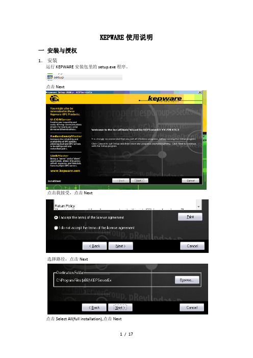
KEPWARE使用说明一安装与授权1.安装运行KEPWARE安装包里的setup.exe程序。
点击Next点击我接受,点击Next选择路径,点击Next点击Select All(full installation),点击Next点击确定在接下的安装界面中点击Next,直到出现完成界面,点击Finish完成。
2.授权运行授权文件,Kepware.KEPServerEX.v4.270.416-Keygen.exe以Modbus ASCII Device Driver为例,其他类似,Driver Name里选择Modbus ASCII Device Driver复制License:中的9-20041-59051721481-3217到KepServerEX中的Help License a Plut-in…在Drivers:Name中选择同样的驱动Modbus ASCII Device Driver,点击License…将授权得到的授权号9-20041-59051721481-3217,复制到License框中,点击OK点击是(Y)复制Computer ID中的:1230923-237756953到授权中粘贴刚才得到的Computer ID,1230923-237756953,到Computer ID中,并复制Unlock:中的028625035210496,到软件中粘贴刚才得到的Unlock,028625035210496,到软件中的Password,点击OK授权成功注:1.下图中的基础内容必须全部完成注册,特别是OPC Data Exchange Server。
2.OPC通讯对应的驱动是下图中OPC DA Client Driver。
二变量连接1.添加通道点击File New,新建工程,点击或者View下方的来添加通道。
在Chanel name中输入通道名,建议用所连接的控制器类型作为通道名。
点击下一步。
Mercedes-Benz Fahrwerkvermessung软件操作手册说明书

Mercedes-Benz FahrwerkvermessungIntroductionThis manual illustrates certain procedures which must be carried out when measuring the setup of Mercedes Benz vehicles. They apply only to Mercedes Benz and they must be followed scru-pulously when controlling and adjusting the setup.This integration refers only to procedures applied exclusively to Mercedes-Benz vehicles. Refer to the main instructions manual, which can be accessed by pressing “F1” in the main menu or by clicking on the question mark on the top left, for the standard operations and instructions on using the software. Select the desired topic from the contents to view further explanations.Table of ContentsChecking the software installed and the active databank (4)Romess inclination measuring instrument connected (4)System configuration (4)Measuring points check system (MKS) (4)Main menu (5)Selection (5)Client data (5)Mercedes tyres information (6)Vehicle selection Make (6)Vehicle selection Model (6)Claw selection (6)Preparing the initial measurement (7)Camber measurement with zero toe-in (7)Measuring the caster / inclination of the kingpin / track difference (7)Steering wheel alignment and blockage (7)Checking the steering control and the front axis (8)Determining the setup (8)Results of the initial measurement (9)Determining/controlling the setup (9)Displaying the rear measurements (10)Displaying the front measurements (10)Preparing the front toe-in setting (11)Setting the front toe-in (11)Concluding the front toe-in setting (11)Preparing the final measurement (11)Camber measurement with zero toe-in (12)Measuring the caster / inclination of the kingpin / track difference (12)Results of the initial and final measurement (12)Print measurement sheet / record (13)Checking the software installed and theactive databankClick on F12 in the tool bar of the main menu to display the information shown here.\In the example the software version is PRO42 3.0 and the active databank is V2.04Romess inclination measuring instrumentconnectedFrom the Home Screen select “Grundeinstel-lungen” (Features) From the side Carousel bar. Then select “Einstellungen der Periph-eriegerate” (Connectivity Option) to open the screen shown here. Activate “Romess Incli-nometer” by clicking on the toggle switch.The inclination measurement instrument is now activated (see yellow arrow).System configuration• This screen is used to configure the cam-eras, and if a control camera is installedsubsequently.• Select the wheel clamps to used during the alignment.• Select if a ride height target is to be used.Measuring points check system (MKS) When the aligner is switched on the measur-ing point and work station control procedure isdisplayed automatically.Follow the on-screen instructions.If all the values of the control screen are green, the system and the work station are setup correctly.If they are not, check the aligner and the work station.The aligner can be checked with the software function. Click on“System testen” (system test) (see yellow ar-row) and follow the on-screen instructions.Main menuFrom the main menu the operator canstart a Mercedes-Benz measurementora measurement for other manufactur-ers vehicles.SelectionIn this window the operator can proceed with the setup measurement or access the mea-suring points control system (MKS), at any stage.Client dataThis screen is used to enter the client data, the operator name, the reason for the mea-surement, the vehicle type approval and the mileage.This data is saved in a databank and they can be accessed at any time, e.g. when the ve-hicle must be measured again.If the mileage is updated, the measurement can be performed with the previous data.The old record can be printed at any timeMercedes tyres informationThis screen is used to document the current state of all the tyres fitted on the vehicle dur-ing the measurement.Obviously this information will also appear in the measurement sheet.Vehicle selection MakeThe following vehicle manufacturers can be selected in this screen: MAYBACH, MER-CEDES-BENZ, SMART or TRANSPORTER After having selected the manufacturer, the operator must select the model (series).Vehicle selection ModelAfter selecting the manufacturer and model, the operator must select the sub-model.Claw selectionUse the MB quick release claws for all Mer-cedes vehicles with original tyres.This is the only way to guarantee that the measurement can be performed correctly in compliance with the applicable standards.An exception may have to be made with a Sprinter or a Mercedes vehicle with alloy rims. In such cases the operator must select the standard claw and perform a positioning.Preparing the initial measurementTo start the initial measurement the operator must install the brake lock.The front rotating plates and the rear rotating/ mobile plates must be released.This sequence must be strictly followed! Camber measurement with zero toe-inAt the beginning of the steering procedure the camber is measured on the front axis with zero toe-in.Follow the on-screen instructions. Measuring the caster / inclination of thekingpin / track differenceAt the end of the camber measurement with zero toe-in, the steering procedure is per-formed to measure the caster, the inclination of the kingpin and the track difference.This is performed by turning the front wheels left once, and turning them right once.Follow the on-screen instructions.Steering wheel alignment and blockageAt the end of the steering procedure, the steering wheel must be aligned and blocked with the steering lock.A steering wheel alignment tool is available from Romess.Checking the steering control and the frontaxisAfter having installed the steering lock, fit the toe-in bar between the front wheels.The toe-in bar is used to move the front wheels towards the toe-out. This is to checkif the steering control and the front axis have any excess play.Checking the steering control and the frontaxisIf the screen shown on the left is displayed, remove the toe-in bar once again.The screens shown here are used to checkif the toe-in bar and the front axis have any excess play.Any excess play is shown on the screen. Determining the setupThe setup is calculated with the Romess incli-nation measurement instrument.The setup must be measured on the four halves of the axes.The calculation of the setup is used to checkif the vehicle is in a condition to allow a mea-surement and in order to use the setup mea-surement to calculate the relevant nominal values.Determining the setupAt the end of the setup measurement, the in-clination measurement instrument is connect-ed to the aligner computer in order to transfer the values measured.The position of the balls must be measured only in older vehicles with recirculating balls steering.The adjustment point must also be measured only in older vehicles; this is to check the op-eration of the setup adjustment system on the rear axis.Determining the setupThe software checks, based on the databank installed, if the vehicle being measured com-plies with the standards. If it does not, the corresponding error message is automatically displayed.The operator can eliminate the error or errors with a repair or other.Results of the initial measurementAfter having completed the steering proce-dure, the steering check, checking the playof the front axis joint and having calculated the vehicle setup based on the applicable standards, the following screen is displayed “Anzeige aller Meßwerte” (display all values measured).The “Vorher” (prima) column lists the results of the initial measurement. The column be-tween “Vorher” (initial) and “Nachher” (final) provides information on the corresponding nominal values, including relative tolerances. Most of the measured values are displayed in colour, that is if the values measured are with-in the allowed tolerance, they are in green. If they are not within the allowed tolerance, they are in red.Determining/controlling the setupIf the initial measurement analysis reveals that due to incorrect heights the actual values are beyond the allowed tolerances, the operator can perform the necessary repairs here.If the setup did not have to be corrected, the software automatically extracts the data from the initial measurement of the setup.If a correction is performed, obviously the setup changes and the operator can now perform a second measurement to continue working with the updated values.Displaying the rear measurementsAfter having performed the initial measure-ment and having calculated the correct setup, the comparators for the rear axis are dis-played.All the values are shown “live”.The upper comparators provide information on the rear camber, the central comparators provide information on the rear toe-in and the lower comparator information on the geomet-ric thrust angle.This screen is used to perform the settings required for the rear axis.Logically the camber is set first, followed by the toe-in.The left rear camber comparator in detail.The upper line displays the theoretical value (here -1.3°), the minimum theoretical value (here -0.8°) and the maximum theoretical value (here -1.8°). The actual value is -1.3°If the actual value is displayed with a green background, it is within the tolerance window. Displaying the front measurementsIf the rear axis has been adjusted success-fully, the front comparators are displayed.The upper comparators provide information on the front caster, the central comparators provide information on the front camber and the lower comparators provide information on the front toe-in.As the caster values are displayed “live”, the caster and/or the camber can be set in this screen.Here the nominal values with tolerances are not displayed for the toe-in.Just ensure that the caster and/or the camber are set with “zero” toe-in.Furthermore what was set out earlier applies here too.Preparing the front toe-in settingIn older vehicles with recirculating balls steer-ing, fit the centring pin for the central position of the steering control.In all vehicles use the toe-in bar according to the indications.Setting the front toe-inThis screen is used to set the front axis toe-in: Nominal values are also displayed with the relative tolerances inside (Innen) the com-parator.Concluding the front toe-in settingIf the front axis toe-in has been set correctly, remove the toe-in bar and the centring pin (in older vehicles).Preparing the final measurementRemove the steering lock.In order to start the final measurement, install the brake lock.Furthermore the front rotating plates and the rear rotating/mobile plates must be released. This sequence must be strictly followed!Camber measurement with zero toe-inAt the beginning of the steering procedure the camber is measured on the front axis with zero toe-in.Follow the on-screen instructions.Measuring the caster / inclination of thekingpin / track differenceAt the end of the camber measurement with zero toe-in, the steering procedure is per-formed to measure the caster, the inclinationof the kingpin and the track difference.This is performed by turning the front wheels left once, and turning them right onceFollow the on-screen instructions.Measuring the caster / inclination of the king-pin / track differenceThe screen on the left shows that the steering to the left has been completed and the steer-ing to the right is partially complete.Note: The software requires a maximum steering angle only for vehicles with nominal values for the maximum steering angle and nominal values for the relative tolerances!Results of the initial and final measure-mentThis screen “Anzeige aller Messwerte” (dis-play all values measured) displays, in the “Vorher” (initial) column the result of the initial measurement and in the “Nachher” (final) col-umn the result of the final measurement.The nominal values with the relative toleranc-es are shown between the two columns.If all the setting operations have been per-formed successfully, all the values measured will be displayed in green in the “Nachher“ (final) column.Print measurement sheet / recordAt the end of the measurement and the set-ting, the operation is concluded by printing the measurement sheet.Click on the printer icon to print.Click on OK to go back to the main menu.The measurement sheet。
MakerBot Replicator 用户使用手册
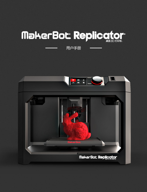
安全性与合规性
在开始之前,让我们回顾一些重要的安全信息。
无线电和电视干扰 本设备已经过测试,符合联邦通信委员会 (FCC) 规定第 15 部分针对 B 类数字设备的限制。 这些限制旨在提供合理的 保护,防止在住宅安装中产生有害干扰。 本设备生成、使用并可能辐射射频能量,如果不按照说明进行安装和使用,可 能会对无线电通信产生有害干扰。 不过,不保证在特定安装中不产生干扰。 如果本设备确实对无线电或电视接收产生 有害干扰(可通过关闭再打开本设备来确定),我们鼓励用户通过以下一种或多种措施来消除干扰:
MAKERBOT REPLICATOR 控制面板
MakerBot® Replicator® 通过机器右上角的控制面板进行操作。 控制面板中包含一个彩色 LCD 屏 幕、一个旋转/按压式转盘和两个按钮。
1
2
3
4
5
1. LCD 屏幕 2. 菜单按钮 3. 后退按钮
4. 转盘 5. USB 驱动器端口
i 注意: 油漆工使用的蓝色遮蔽胶带能够形成一个极佳的表面,可以在其上用 PLA 材料打印物体。 您可以在 /store 上找到其他打印托盘尺寸的蓝色胶带,也可以从任何硬件商店购 买成卷的蓝色胶带。
16 快速入门
设置 MAKERBOT REPLICATOR
4 插上插头并通电
10
11
12
13
14
10. LCD 屏幕 11. 菜单按钮 12. 后退按钮
13. 转盘 14. USB 驱动器端口
14. USB 线缆 15. 以太网线缆 16. 电源输入端口
9
欢迎,让我们开始吧
14
15
16
2
快速入门
在安装 MakerBot® Replicator® 桌面 3D 打印机时,请记 住,该打印机在 MakerBot 工厂经过精心制造和仔细包装。 希望您多用点时间,小心地拆卸包装并进行安装。
Cookware 使用指南说明书
Cookware
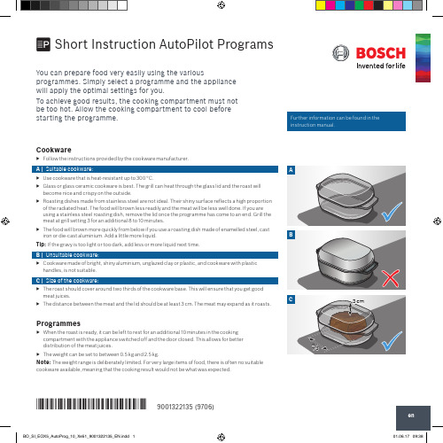
▶▶ Follow the instructions provided by the cookware manufacturer.
A | Suitable cookware:
A
▶▶ Use cookware that is heat-resistant up to 300 °C.
▶▶ Glass or glass ceramic cookware is best. The grill can heat through the glass lid and the roast will become nice and crispy on the outside.
Programme duration ▶▶ Your appliance will automatically calculate how long the programme you
have set is going to take. The programme duration will be displayed once you have set the weight for your chosen programme.
Programmes
▶▶ When the roast is ready, it can be left to rest for an additional 10 minutes in the cooking
compartment with the appliance switched off and the door closed. This allows for better
3 cm
*9001322135* 9001322135 (9706)
Labelmakers Easy-Mark软件说明书
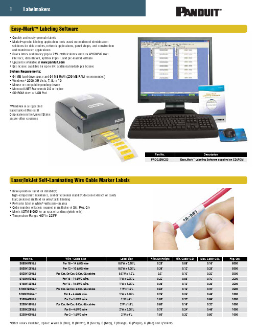
1Easy-Mark™ Labeling Software• Quickly and easily generate labels• Market-specific labeling application tools assist in creation of identification solutions for data centers, network applications, panel shops, and construction and maintenance applications• Saves times and money (up to 75%) with features such as WYSIWYG user interface, data import, symbol import, and pre-loaded formats • Upgrades available at • Site license available for up to five additional installs per license System Requirements:• 64 MB hard drive space and 64 MB RAM (256 MB RAM recommended)• Windows* 2000, XP , Vista, 7, 8, or 10• Mouse or compatible pointing device • Framework 2.0 or higher • CD-ROM drive or USB PortPart No.DescriptionPROG-EMCD3Easy-Mark™ Labeling Software supplied on CD-ROM*Windows is a registered trademark of MicrosoftCorporation in the United States and/or other countriesLaser/InkJet Self-Laminating Wire Cable Marker Labels• Indoor/outdoor rated for durability;high-temperature resistance, and dimensional stability; does not stretch or easily tear; preferred method for wire/cable labeling • Polyester label is white* with print-on area• Order number of labels required in multiples of Std. Pkg. Qty • Meets ASTM E-595 for air space handling (white only)• Temperature Range: -65° to 225°F*Other colors available, replace A with B (Blue), C (Brown), D (Green), E (Gray), F (Orange), G (Purple), H (Red) and I (Yellow).2800.777.3300 | Thermal Transfer Desktop Printer and Accessories• Compact, lightweight design enables use in office or remote locations• 300 dpi thermal transfer printer creates crisp, clear legends with superior legibility • Up to 2.00 inches per second print speed for fast label production • Use to print a wide variety of self-laminating labels, component labels, non-laminated labels, heat shrink labels, marker plates and continuous tapes up to 4.00 inches wide• Easy-Mark™ Labeling Software and hybrid ribbon included with printer*For 2.5" wide ribbons, replace 4 in part number with 2. For example, the part number of a 2.5" wide black hybrid thermal transfer ribbon is RMEH2BL.Ribbons for Use with the TDP43ME Thermal Transfer Desktop Printer• Hybrid – Recommended for use with self-laminating, heat shrink, component and non-laminated labels• Resin – Recommended for use with component labels, marker plates, and continuous tape• 4.3" x 240-ft. (110mm x 73m)Thermal Transfer Continuous Label Tapes• Tapes offer crisp, clear legends with superior legibility • Indoor/outdoor rated• Conformable flat label applications for safety and facility identification• Can be overlaminated to increase durability• Use thermal transfer resin ribbon• Vinyl Tapes: 4" x 100-ft.• Reflective Tapes: 4" x 50-ft.Thermal Transfer Printable Arc Flash Labels• Provide employees with the highest degree of safety through proper identification and communication• Clearly visible and recognizable hazard information to communicate arc flash hazards present• Labels are constructed of durable polyester designed to withstand UV exposure, outdoor use, water, abrasion• Custom Arc Flash Hazard Labels can be printed using Panduit labeling software with desktop thermal transfer printers • Use thermal transfer resin ribbonCustom Die-CutCustom Continuous Color Header Tape4" x 4"C400X400A51250/Roll4" x 4"C400X400YZ1250/Roll4" x 6"C400X600A51100/Roll4" x 6"C400X600YX1100/Roll 4" x 6"C400X600YZ1100/RollT400X000A91T400X000YX1Vinyl Tapes, 4" x 100-ft.Reflective Tapes, 4" x 50-ft.Non-Printable Clear Overlaminate Tapes, 4.25" x 100-ft.• Temperature Ranges:Vinyl: -58° to 176°F Polyester: -40° to 302°F Reflective: -40° to 180°F3PanTher™ Hand-Held Thermal Transfer Printer and Accessories• Cut-to-length functionality eliminates label waste and label trimming labor • Partial cut feature available to provide tear-apart strips of labels• P1™ Label Cassette contains an integrated memory device for automatic formatting, recall of last legend used, and number of labels remaining in the cassette• Market specific labeling tools simplify label creation for electrical components, panel building, and construction and maintenance• USB interface for importing data, system upgrades, and printing from a wireless laptop or desktop computer• Prints self-laminating labels, heat shrink tubing, die-cut component labels and continuous tapes• Fast loading label cassette includes both label material and ribbon to make changing labels easy• Large graphic display with backlight for improved visibilityP1™ Continuous Tape Cassettes for PanTher™ LS8EQ Hand-Held Thermal Transfer Printers• Fast loading label cassette includes both label material and ribbon to make changing labels easy• Print custom pipe markers, voltage markers, signs and bin marker labels on demand • Available in a variety of colors, in polyester and vinyl adhesive materials • For flat label applications only • 1" x 25-ft.• Polyester temperature range: -40° to 302°F• Vinyl temperature range: -50° to 225°FP1™ Continuous Reflective Tape Cassettes for PanTher™ LS8EQ and Hand-Held Thermal Transfer Printers• Fast loading P1™ Label Cassette includes both label material and ribbon to make changing labels easy• Reflective material improves label visibility in low light conditions • For flat label applications only • 1" x 18-ft.• Reflective temperature range: -40° to 180°FMetal Embossing Hand Tool and Tape System• Multi-functional cutting die design creates embossed marker plates with raised cable tie slot in one step instead of three, for faster installation• Lightweight, compact, and portable, allows user to create custom length identification on demand at remote job sites• Embosses 3/16" characters (A-Z, 1-9, /, ( ) onto stainless steel or aluminum tape, to improvevisibility in applications that are subjected to dirt or paint*Aluminum ties are recommended for use with aluminum tape to prevent galvanic reaction (corrosion that can occur between stainless steel andaluminum in certain environments).。
MAKER使用指南说明书
Exercise 1. Using MAKER for Genome AnnotationIf you are following this guide for your own research project, please make the following modifications:1. In this exercise, SNAP was used for gene prediction. When you are working on your owngenome, we recommend that you use Augustus. The instructions for using Augustus is in appendix.2. In the exercise, you will be using 2 CPU cores. When you are working on your own genome,you should use all CPU cores on your machine. When you run the command:"/usr/local/mpich/bin/mpiexec -n 2", replace 2 with number of cores available on yourmachine.3. The steps for Repeatmodeler and Repeatmasker are optional in the exercise, but requiredwhen you work on your own genome.The example here is from a workshop by Mark Yandell Lab (/ ) Further readings:1. Yandel Lab Workshop. /MAKER/wiki/index.php/MAKER_Tutorial_for_WGS_Assembly_and_Annotation_Winter_School_2018 .2. MAKER protocol from Yandell Lab. It is good reference. https:///pmc/articles/PMC4286374/3. Tutorial for training Augustus https:///simonlab/bioinformatics/programs/augustus/docs/tutorial2015/training.html4. Maker control file explained: /MAKER/wiki/index.php/The_MAKER_control_files_explainedPart 1. Prepare working directory.1. Copy the data file from /shared_data/annotation2018/ into /workdir/$USER, and de-compress the file. You will also copy the maker software directory to /workdir/USER. The maker software directory including a large sequence repeats database. It would be good to put it under /workdir which is on local hard drive.mkdir /workdir/$USERmkdir /workdir/$USER/tmpcd /workdir/$USERcp /shared_data/annotation2019/maker_tutorial.tgz ./cp -rH /programs/maker/ ./cp -rH /programs/RepeatMasker ./tar -zxf maker_tutorial.tgzcd maker_tutorialls -1Part 2. Maker round 1 - Map known genes to the genomeRun everything in "screen".Round 1 includes two steps:Repeat masking;Align known transcriptome/protein sequences to the genome;1. [Optional] Build a custom repeat database. This step is optional for this exercise, as it is avery small genome, it is ok without repeat masking. When you work on a real project, you can either download a database from RepBase (https:///repbase/, license required), or you can build a custom repeat database with your genome sequence.RepeatModeler is a software for building custom databases. The commands for building a repeat database are provided here.cd example_02_abinitioexport PATH=/programs/RepeatModeler-2.0:$PATHBuildDatabase -name pyu pyu_contig.fastaRepeatModeler -pa 4 -database pyu -LTRStruct >& repeatmodeler.logAt the end of run, you would find a file "pyu-families.fa". This is the file you can supply to "rmlib=" in the control file.2. Set environment to run Maker and create MAKER control files.Every steps in Maker are specified by the Maker control files. The command "maker -CTL" will create three control files: maker_bopts.ctl, maker_exe.ctl, maker_opts.ctl.by.exportPATH=/workdir/$USER/maker/bin:/workdir/$USER/RepeatMasker:/programs/snap:$PATH export ZOE=/programs/snap/Zoeexport LD_LIBRARY_PATH=/programs/boost_1_62_0/libcd /workdir/$USER/maker_tutorial/example_02_abinitiomaker -CTL3. Modify the control file maker_opts.ctl.Open the maker_opts.ctl file in a text editor (e.g. Notepad++ on Windows, BBEdit on Mac, or vi on Linux). Modify the following values. Put the modified file in the same directory“example_02_abinitio”.genome=pyu_contig.fastaest=pyu_est.fastaprotein=sp_protein.fastamodel_org=simplermlib= #fasta file of your repeat sequence from RepeatModeler. Leave blank to skip.softmask=1est2genome=1protein2genome=1TMP=/workdir/$USER/tmp #important for big genome, as the default /tmp is too smallThe modified maker_opts.ctl file instructs MAKER to do two things.a) Run RepeatMasker.The line “model_org=simple” tells RepeatMasker to mask the low complexity sequence (e.g.“AAAAAAAAAAAAA”.The line “rmlib=” sets "rmlib" to null, which tells RepeatMasker not to mask repeatsequences like transposon elements. If you have a repeat fasta file (e.g. output fromRepeatModeler) that you need to mask, put the fasta file name next to “rmlib=”The line “softmask=1” tells RepeatMasker to do soft-masking which converts repeats tolower case, instead of hard-masking which converts repeats to “N”. "Soft-masking" isimportant so that short repeat sequences within genes can still be annotated as part of gene.If you run RepeatMasker separately, as described in https:///darencard/bb10 01ac1532dd4225b030cf0cd61ce2 , you should leave rmlib to null, but set rm_gff to a repeat gff file.b) Align the transcript sequences from the pyu_est.fasta file and protein sequences from thesp_protein.fasta file to the genome and infer evidence supported gene model.The lines “est2genome=1” and “protein2genome=1” tell MAKER to align the transcriptsequences from the pyu_est.fasta file and protein sequences from the sp_protein.fasta file to the genome. These two files are used to define evidence supported gene model.The lines “est=pyu_est.fasta" and "protein=sp_protein.fasta" specify the fasta file names of the EST and protein sequences. In general, the EST sequence file contains the assembled transcriptome from RNA-seq data. The protein sequence file include proteins from closely related species or swiss-prot. If you have multiple protein or EST files, separate file names with ",".4. [Do it at home] Execute repeat masking and alignments. This step takes an hour. Run it in"screen". In the command: "mpiexec -n 2 " means that you will parallelize Maker using MPI, and use two threads at a time. When you work on a real project, it will take much longer, and you should increase this "-n" setting to the number of cores.Set Maker environment if it is new session:exportPATH=/workdir/$USER/maker/bin:/workdir/$USER/RepeatMasker:/programs/snap:$PATH export ZOE=/programs/snap/Zoeexport LD_LIBRARY_PATH=/programs/boost_1_62_0/libExecute the commands:cd /workdir/qisun/maker_tutorial/example_02_abinitio/usr/local/mpich/bin/mpiexec -n 2 maker -base pyu_rnd1 >& log1 &After it is done, you can check the log1 file. You should see a sentence: Maker is now finished!!!Part 3. Maker round 2 - Gene prediction using SNAP1. Train a SNAP gene model.SNAP is software to do ab initio gene prediction from a genome. In order to do gene prediction with SNAP, you will first train a SNAP model with alignment results produced in the previous step.If you skipped the step "4. [Do it at home] Execute Maker round 1", you can copy the result files from this directory: /shared_data/annotation2019/cd /workdir/qisun/maker_tutorial/example_02_abinitiocp /shared_data/annotation2019/pyu_rnd1.maker.output.tgz ./tar xvfz pyu_rnd1.maker.output.tgzSet Maker environment if it is new session:exportPATH=/workdir/$USER/maker/bin:/workdir/$USER/RepeatMasker:/programs/snap:$PATH export ZOE=/programs/snap/Zoeexport LD_LIBRARY_PATH=/programs/boost_1_62_0/libThe following commands will convert the MAKER round 1 results to input files for building a SNAP mode.mkdir snap1cd snap1gff3_merge -d ../pyu_rnd1.maker.output/pyu_rnd1_master_datastore_index.logmaker2zff -l 50 -x 0.5 pyu_rnd1.all.gffThe “-l 50 -x 0.5” parameter in maker2zff commands specify that only gene models with AED score>0.5 and protein length>50 are used for building models. You will find two new files: genome.ann and genome.dna.Now you will run the following commands to train SNAP. The basic steps for training SNAP are first to filter the input gene models, then capture genomic sequence immediately surrounding each model locus, and finally uses those captured segments to produce the HMM. You can explore the internal SNAP documentation for more details if you wish.fathom -categorize 1000 genome.ann genome.dnafathom -export 1000 -plus uni.ann uni.dnaforge export.ann export.dnahmm-assembler.pl pyu . > ../pyu1.hmmmv pyu_rnd1.all.gff ../cd ..After this, you will find two new files in the directory example_02_abinitio:pyu_rnd1.all.gff: A gff file from round 1, which is evidence based genes.pyu1.hmm: A hidden markov model trained from evidence based genes.2. Use SNAP to predict genes.Modify directly on the maker_opts.ctl file that you have modified previously.Before doing that, you might want to save a backup copy of maker_opts.ctl for round 1.cp maker_opts.ctl maker_opts.ctl_backup_rnd1Now modify the following values in the file: maker_opts.ctlRun maker with the new control file. This step takes a few minutes. (A real project could take hours to finish). You will use the option “-base pyu_rnd2” so that the results will be written into a new directory "pyu_rnd2".Again, make sure the log2 file ends with "Maker is now finished!!!".Part 4. Maker round 3 - Retrain SNAP model and do another round of SNAP gene predictionYou might need to run two or three rounds of SNAP . So you will repeat Part 2 again. Make sure you will replace snap1 to snap2, so that you would not over-write previous round.1. First train a new SNAP model.2. Use SNAP to predict genes.Modify directly on the maker_opts.ctl file that you have modified previously.Before doing that, you might want to save a backup copy of maker_opts.ctl for round 2.Now modify the following values in the file: maker_opts.ctlmaker_gff= pyu_rnd1.all.gffest_pass=1 # use est alignment from round 1protein_pass=1 #use protein alignment from round 1rm_pass=1 # use repeats in the gff filesnaphmm=pyu1.hmmest= # remove est file, do not run EST blast againprotein= # remove protein file, do not run blast againmodel_org= #remove repeat mask model, so not running RM againrmlib= # not running repeat masking againrepeat_protein= #not running repeat masking againest2genome=0 # do not do EST evidence based gene modelprotein2genome=0 # do not do protein based gene model.pred_stats=1 #report AED statsalt_splice=0 # 0: keep one isoform per gene; 1: identify splicing variants of the same genekeep_preds=1 # keep genes even without evidence support, set to 0 if no/usr/local/mpich/bin/mpiexec -n 2 maker -base pyu_rnd2 >& log2 &mkdir snap2cd snap2gff3_merge -d ../pyu_rnd2.maker.output/pyu_rnd2_master_datastore_index.logmaker2zff -l 50 -x 0.5 pyu_rnd2.all.gfffathom -categorize 1000 genome.ann genome.dnafathom -export 1000 -plus uni.ann uni.dnaforge export.ann export.dnahmm-assembler.pl pyu . > ../pyu2.hmmmv pyu_rnd2.all.gff ..cd ..cp maker_opts.ctl maker_opts.ctl_backup_rnd2maker_gff=pyu_rnd2.all.gffsnaphmm=pyu2.hmmRun Maker:/usr/local/mpich/bin/mpiexec -n 2 maker -base pyu_rnd3 >& log3 &Use the following command to create the final merged gff file. The “-n” option would produce a gff file without genome sequences:gff3_merge -n -dpyu_rnd3.maker.output/pyu_rnd3_master_datastore_index.log>pyu_rnd3.noseq.gff fasta_merge -d pyu_rnd3.maker.output/pyu_rnd3_master_datastore_index.logAfter this, you will get a new gff3 file: pyu_rnd3.noseq.gff, and protein and transcript fasta files. 3. Generate AED plots./programs/maker/AED_cdf_generator.pl -b 0.025 pyu_rnd2.all.gff > AED_rnd2/programs/maker/AED_cdf_generator.pl -b 0.025 pyu_rnd3.noseq.gff > AED_rnd3You can use Excel or R to plot the second column of the AED_rnd2 and AED_rnd3 files, and use the first column as the X-axis value. The X-axis label is "AED", and Y-axis label is "Cumulative Fraction of Annotations "Part 5. Visualize the gff file in IGVYou can load the gff file into IGV or JBrowse, together with RNA-seq read alignment bam files. For instructions of running IGV and loading the annotation gff file, you can read under "part 4" of this document:/doc/RNA-Seq-2019-exercise1.pdfAppendix: Training Augustus modelRun Part 1 & 2.In the same screen session, set up Augustus environment.cp -r /programs/Augustus-3.3.3/config/ /workdir/$USER/augustus_configexport LD_LIBRARY_PATH=/programs/boost_1_62_0/libexport AUGUSTUS_CONFIG_PATH=/workdir/$USER/augustus_config/export LD_LIBRARY_PATH=/programs/boost_1_62_0/libexport LC_ALL=en_US.utf-8export LANG=en_US.utf-8export PATH=/programs/augustus/bin:/programs/augustus/scripts:$PATHThe following commands will convert the MAKER round 1 results to input files for building a SNAP mode.mkdir augustus1cd augustus1gff3_merge -d ../pyu_rnd1.maker.output/pyu_rnd1_master_datastore_index.logAfter this step, you will see a new gff file pyu_rnd1.all.gff from round 1.## filter gff file, only keep maker annotation in the filtered gff fileawk '{if ($2=="maker") print }' pyu_rnd1.all.gff > maker_rnd1.gff##convert the maker gff and fasta file into a Genbank formated file named pyu.gb ##We keep 2000 bp up- and down-stream of each gene for training the modelsgff2gbSmallDNA.pl maker_rnd1.gff pyu_contig.fasta 2000 pyu.gb## check number of genes in training setgrep -c LOCUS pyu.gb## train model## first create a new Augustus species namednew_species.pl --species=pyu## initial trainingetraining --species=pyu pyu.gb## the initial model should be in the directoryls -ort $AUGUSTUS_CONFIG_PATH/species/pyu##create a smaller test set for evaluation before and after optimization. Name the evaluation set pyu.gb.evaluation.randomSplit.pl pyu.gb 200mv pyu.gb.test pyu.gb.evaluation# use the first model to predict the genes in the test set, and check theresultsaugustus --species=pyu pyu.gb.evaluation >& first_evaluate.outgrep -A 22 Evaluation first_evaluate.out# optimize the model. this step is very time consuming. It could take days. To speed things up, you can create a smaller test set# the following step will create a test and training sets. the test set has 1000 genes. This test set will be splitted into 24 kfolds for optimization (the kfold can be set up to 48, with processed with one cpu core per kfold. Kfold must be same number as as cpus). The training, prediction and evaluation will beperformed on each bucket in parallel (training on hh.gb.train+each bucket, then comparing each bucket with the union of the rest). By default, 5 rounds of optimization. As optimization for large genome could take days, I changed it to3 here.randomSplit.pl pyu.gb 1000optimize_augustus.pl --species=hh --kfold=24 --cpus=24 --rounds=3 --onlytrain=pyu.gb.train pyu.gb.test >& log &#train again after optimizationetraining --species=pyu pyu.gb# use the optionized model to evaluate again, and check the resultsaugustus --species=pyu pyu.gb.evaluation >& second_evaluate.outgrep -A 22 Evaluation second_evaluate.outAfter these steps, the species model is in the directory/workdir/$USER/augustus_config/species/pyu.Now modify the following values in the file: maker_opts.ctlmaker_gff= pyu_rnd1.all.gffest_pass=1 # use est alignment from round 1protein_pass=1 #use protein alignment from round 1rm_pass=1 # use repeats in the gff fileaugustus_species=pyu # augustus species model you just builtest= # remove est file, do not run EST blast againprotein= # remove protein file, do not run blast againmodel_org= #remove repeat mask model, so not running RM againrmlib= # not running repeat masking againrepeat_protein= #not running repeat masking againest2genome=0 # do not do EST evidence based gene modelprotein2genome=0 # do not do protein based gene model.pred_stats=1 #report AED statsalt_splice=0 # 0: keep one isoform per gene; 1: identify splicing variants of the same genekeep_preds=1 # keep genes even without evidence support, set to 0 if noRun maker with the new augustus model/usr/local/mpich/bin/mpiexec -n 2 maker -base pyu_rnd3 >& log3 &Create gff and fasta output files:Use the following command to create the final merged gff file. The “-n” option would produce a gff file without genome sequences:gff3_merge -n -dpyu_rnd3.maker.output/pyu_rnd3_master_datastore_index.log>pyu_rnd3.noseq.gff fasta_merge -d pyu_rnd3.maker.output/pyu_rnd3_master_datastore_index.logAfter this, you will get a new gff3 file: pyu_rnd3.noseq.gff, and protein and transcript fasta files. To make the gene names shorter, use the following commands:maker_map_ids --prefix pyu_ --justify 8 --iterate 1 pyu_rnd3.all.gff > id_map map_gff_ids id_map pyu_rnd3.all.gffmap_fasta_ids id_map pyu_rnd3.all.maker.proteins.fastamap_fasta_ids id_map pyu_rnd3.all.maker.transcripts.fasta。
软件使用说明书

HOWOLASER用户使用手册HOWOLASER Client Use handBook由于软件升级所造成的实际操作方式、功能设置等,如有与本手册不符之处,以软件为准。
HOWOLASER激光打标机用户使用手册目录第一章概述 (5)1.1EzCad2软件简介 (5)1.1.1软件安装 (5)1.1.2软件功能 (5)1.1.3界面说明 (6)1.2本手册说明 (7)1.2.1内容安排 (7)1.2.2其他声明 (7)第二章文件菜单 (8)2.1新建(N) (8)2.2打开(O) (9)2.3保存(S),另存为(A) (10)2.4打印 (11)2.5获取扫描图像(m) (11)2.6系统参数(P) (11)2.6.1常规 (12)2.6.2颜色 (13)2.6.3工作空间 (13)2.6.4自动备份 (13)2.6.5移动旋转 (14)2.6.6插件管理器 (14)2.6.7语言/Language (15)2.7最近文件 (15)2.8退出(X) (16)2.9对象列表 (16)2.10对象属性栏 (16)第三章编辑 (19)3.1撤消(U)/恢复(R) (19)3.2剪切(T)/复制(C)/粘贴(P) (19)3.3组合/分离组合 (20)3.4群组/分离群组 (20)3.5填充 (21)HOWOLASER激光打标机用户使用手册3.6转为曲线 (24)第四章绘制菜单 (25)4.1点(D) (25)4.2曲线 (26)4.3矩形 (27)4.4圆 (27)4.5椭圆 (28)4.6多边形 (29)4.7文字 (29)4.7.1文字字体参数 (29)4.7.2曲线排文本参数 (31)4.7.3条形码字体参数 (35)4.7.4变量文本 (39)4.8位图 (50)4.9矢量文件 (54)4.10延时器 (56)4.11输入口 (56)4.12输出口 (57)4.13直线 (57)4.14图形选取 (58)4.15节点编辑 (60)第五章修改菜单 (63)5.1变换 (63)5.1.1移动 (63)5.1.2旋转 (64)5.1.3镜像 (65)5.1.4缩放 (65)5.1.5倾斜 (66)5.2造形 (67)5.3曲线编辑 (68)5.4对齐 (68)第六章查看菜单 (73)6.1观察 (73)6.2标尺,网格点,辅助线 (74)HOWOLASER激光打标机用户使用手册6.3捕捉网格 (74)6.4捕捉辅助线 (74)6.5捕捉对象 (74)6.5系统工具栏、视图工具栏、绘制工具栏、状态栏、对象列表栏、对象属性栏 (75)第七章帮助 (76)7.1关于EzCad(A) (76)第八章加工 (77)8.1笔列表 (77)8.2加工参数库 (78)8.3加工对话框 (84)8.4设备参数 (85)8.4.1区域参数 (85)8.4.2激光参数 (88)8.4.3端口参数 (90)HOWOLASER激光打标机用户使用手册第一章概述1.1EzCad2软件简介1.1.1软件安装EzCad2软件运行需要硬件为计算机主频在300MHz以上,内存64M 以上,硬盘10G以上。
Maker 3.2 专业版用户手册
方正Apabi Maker 3.2专业版用户手册北京方正阿帕比技术有限公司2008年5月本手册内容改动及版本更新将不再另行通知。
本手册的范例中使用的人名、公司名和数据如果没有特别指明,均属虚构。
对于本手册、及本手册涉及的技术和产品,北京方正阿帕比技术有限公司拥有其专利、商标、著作权或其它知识产权,除非得到北京方正阿帕比技术有限公司的书面许可,本手册不授予这些专利、商标、著作权或其它知识产权的许可。
版权所有©(2000-2008)北京方正阿帕比技术有限公司保留所有权利●Founder是北京北大方正集团公司的注册商标。
Apabi是北京方正阿帕比技术有限公司的商标。
●Microsoft、MS-DOS、Windows是Microsoft公司的商标或注册商标。
●其它标牌和产品名称是其各自公司的商标或注册商标。
●方正Apabi Maker的一切有关权利属于北京方正阿帕比技术有限公司所有。
●本手册中所涉及的软件产品及其后续升级产品均由北京方正阿帕比技术有限公司制作并负责全权销售。
北京方正阿帕比技术有限公司地址:北京市海淀区北四环西路52号中芯大厦十二层电话:(010)82179988传真:(010)82179500 82179900邮编:100080北京方正阿帕比技术有限公司为您提供售前咨询及售后技术支持和服务服务电话:(010)82179999服务信箱:apabi@网址:目录I目录第1章概述 (1)1.1 方正Apabi Maker——强大的CEB文件生成器 (1)1.2 主要功能 (2)1.3 新增和改进功能 (2)1.4 有关的基本概念和术语 (3)第2章方正Apabi Maker的安装 (5)2.1 运行环境 (5)2.2 安装 (5)2.3 修复和删除 (9)2.4 运行设定 (10)第3章方正Apabi Maker界面功能介绍 (11)3.1 主菜单 (11)3.1.1 “文件”菜单 (12)3.1.2 “设置”菜单 (13)3.1.3 “帮助”菜单 (14)3.2 工具栏 (15)3.3 信息显示区 (15)第4章方正Apabi Maker的使用入门 (18)4.1 使用Apabi Maker生成CEB文件 (18)4.1.1 转换文件 (18)4.1.2 合并文件 (22)4.1.3 拆分文件 (25)4.2 使用Apabi Maker批量转换多个CEB文件 (27)4.2.1 设置批量转换选项 (28)4.2.2 批量转换 (29)第5章设置方正Apabi Maker的运行参数 (31)IIApabi Maker 3.2专业版用户手册5.1 模板管理器 (31)5.1.1 参数模板的管理 (32)5.1.2 模板参数设置 (34)5.2 安全性设置 (43)5.3 水印设置 (44)第6章高级问题 (46)6.1 补字举例 (46)6.2 字库设置 (49)6.2.1 重置字库 (50)6.2.2 编码映射 (50)6.3 反馈信息 (51)6.3.1 正常信息 (52)6.3.2 警告信息 (52)附录1 常见问题解答(FAQ) (54)附录2 图书转换中的注意事项 (66)附2.1 书版系列排版软件 (66)附2.2 飞腾、维思排版软件 (68)附2.3 图片的参数设置 (68)第1章概述 1第1章概述随着计算机和互联网技术的发展,人们正越来越多地使用计算机和互联网处理各类事务,与此同时信息传播也正发生着翻天覆地的变化。
- 1、下载文档前请自行甄别文档内容的完整性,平台不提供额外的编辑、内容补充、找答案等附加服务。
- 2、"仅部分预览"的文档,不可在线预览部分如存在完整性等问题,可反馈申请退款(可完整预览的文档不适用该条件!)。
- 3、如文档侵犯您的权益,请联系客服反馈,我们会尽快为您处理(人工客服工作时间:9:00-18:30)。
联网获取帮他功能平时使用不多,熟悉即可。
操作详解(以更复杂的双喷头做范例)
将模型拖动至软件界面中或者点击Add打开模型。
注:1.模型路径需要是全英文路径,模型文件名称也要使用英文标识。
2.兼容模型格式:Stl和Obj)
模型可通过左侧使用栏来调整位置、大小以及打印使用喷头。
题前文
Makerware相较于ReplicatorG软件界面设计更加美观、软件优化更加完善、键位设计更加合理,故使用上流畅很多,转码速度也较ReplicatorG更加迅速、稳定。
软件使用
双击快捷方式,打开软件,界面如下。
界面详解
基础界面:(这几个是最常用的按键,熟练掌握这几个按键的功能既能做到随心所欲的操控模型和代码)
工程图视角模式
4.Makerbot/官方设定暂不通用(后为快捷键):
机型选择:单喷头机型选择The Replicator双喷头选择The Replicator(Dual)
5.Servies使用服务(后为快捷键):
关闭后台进程
复位后台进程(杀毒软件误报之后,用以复位操作)
显示后台日至
6.Help帮助(后为快捷键):
关闭软件
保存文件
另存为
生成s3g文件
联机打印(暂不支持)
连接数据库打印(暂不支持)
2.Edit/编辑(后为快捷键):
后退一步
复原一步
剪切模型
复制模型
粘贴模型
原地复制模型
删除
全选模型
取消全选
所有模型自动布局
设置
3.View/视图(后为快捷键):
回归3/4视角
顶视图视角
侧视图视角
前视图视角
透视视角模式(建议选择)
Standard:打印速度中等精度适中
High:打印速度最慢但是精度最高
3.Raft底座:
不打印底座
使用软件显示模型的喷嘴打印底座
使用左喷头打印底座
使用右喷头打印底座
T状模型即底面积较小的模型建议打印时选择底座
4.Supports支撑:
选项和Raft相似,不做重复解释。
打印参数
Quality打印质量:
Infill填充:模型内部填充率,0%为空心,100为实心体(建议15-50%)
Nuber of Shells:外壳层数,喷嘴直径0.4mm,选择1壳厚则为0.4mm、2则为0.8mm,以此类推。
Layer Height:精度设置0.1-0.3mm,0.1mm精度最高。
温度设置
Temperature打印温度:
Home:回归基础视角
+&-:调整视觉焦距
Add导入模型
Make:生成s3g文件
Save:保存文件
Look:拖动视角
Move:移动模型
Turn:旋转模型
Scale:缩放模型
Object:选择喷嘴
Help:帮助
工具栏:
1.File/文件(后为快捷键):
开启新进程
打开新模型
添加新模型
最近打开的模型
软件自带范例
Extruders喷嘴温度
Bulid Plate底板温度
常用材料温度设置
打印速度设置
Speed打印速度:
Speed while Extruding打印速度建议40mm/s
Speed while Traveling空走速度建议70mm/s
最后点击Export生成s3g代码或者x3g代码进行脱机打印。
双喷头可以选择用那个喷头来进行打印。
图注:右喷头
图注:左喷头
(注:双喷头代表颜色可调整,单喷头可不用选择此项)
点击Make调出代码参数页面
界面详解:
1.Left & Right:左右喷头所使用材料快捷选项(注:选择PLA底板默认不加温)。
2.Resolution:快捷精度选择
Low:打印速度精度低但速度快
