FC100 Modbus RTU
上能逆变器后台Modbus对外协议[1]
![上能逆变器后台Modbus对外协议[1]](https://img.taocdn.com/s3/m/af8352fd81c758f5f61f6768.png)
EP系列逆变器Modbus RTU通信协议 V1.31目录1 引言 (1)2 物理接口 (1)2.1 串行通信口 (1)2.2 信息传输 (1)2.3 数据传输速率 (1)2.4 帧间隔时间要求 (1)2.5 通讯方式 (1)3 数据类型 (2)3.1 整型数 (2)3.2 浮点数 (2)3.3 日期时间 (2)3.4 通讯的建立 (2)4 功能列表与应用层数据包定义 (2)4.1 功能列表 (2)4.2 应用层数据包定义 (3)4.2.1 FC2离散量输入读取 (3)4.2.2 FC3/FC4块读取 (3)4.2.3 FC5单个线圈写入 (4)4.2.4 FC6字写入 (4)4.2.5 FC16块写入 (4)4.2.6 错误返回帧 (5)5 命令信息详解 (5)5.1 厂家信息 (6)5.2 模拟量信息(遥测) (6)5.2.1 系统模拟量 (6)5.2.2 时间量 (7)5.2.3 环境数据 (8)5.2.4 直流配电柜模拟量 (8)5.2.5 遥测举例 (8)5.3 参数数据写入(遥调) (9)5.3.1 逆变器系统参数设置 (9)5.3.2 用户通讯接口配置 (10)5.3.3 实时时钟遥调 (10)5.3.4 遥调举例 (11)5.4 遥控命令 (11)5.4.1 遥控举例 (11)5.5 写入数据回读 (11)5.5.1 读取逆变器系统参数 (11)5.5.2 读取用户通信接口配置 (12)5.6 读取系统状态量信息(遥信) (12)5.6.1 遥信举例 (14)5.7 读取告警量(遥信) (15)1引言旨在实现逆变器与后台PC机等串行通信设备主机的串行通信,通过本协议可以把逆变器接入MODBUS RTU系统。
2物理接口2.1串行通信口采用RS485、RS232。
2.2信息传输为异步方式,起始位1位,数据位8位,停止位1位,无校验位。
2.3数据传输速率4800bps/s 9600bps/s 19200bps/s 57600bps/s 115200bps/s ;其中,限于时下PC机自带RS232串口和部分485转232串口所支持的波特率不高,所以对于需要高速波特率(57600bps/s 115200bps/s)时,需要确认PC机或板卡是否支持。
丹佛斯变频器modbus通讯
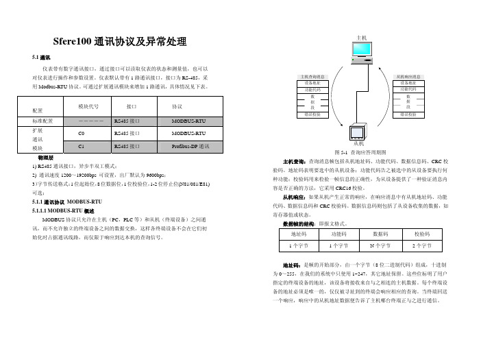
丹佛斯变频器Modbus通讯济南创恒科技发展有限公司满建江∙FC系列变频器通过内置的RS485接口,以Modbus RTU格式进行通讯。
参数设置如表∙FC系列变频器需要设置的参数:8-01,控制地点,选择【2】控制字,或者【0】数字和控制字;8-02,控制来源,选择【1】RS 485;8-03,控制字超时时间;8-04,控制字超时功能,选择当控制字丢失,变频器采取的动作;8-30,【2】选择为Modbus RTU通讯协议;8-31,变频器的通讯地址,1-126范围内地址有效;8-32,设置通讯速度,各站速度要求一致;8-33,奇偶校验方式,各站要求设置一致;8-50,惯性停车的实现方式,当8-01选择为【0】时,请注意该参数。
丹佛斯变频器所要通讯的MODBUS地址为参数号码乘以10减去1,西门子PLC不需要减1. 例如:变频器的频率地址为3-10那么对应的MODBUS地址即是:(310×10)-1=3099(十进制)西门子200PLC 地址不需要减1 为43100在PLC的modbus指令块写入要通讯变频器地址,参数的地址,和参数的值后,即可更改此参数。
∙电报结构(十六进制)∙地址字段包含8位数据,有效的地址范围为0-247(十进制),0为广播模式;1-247对相应地址的从站进行寻址。
功能字段包含8位数据,有效地代码范围为1-FF,功能字段用于在主站和从站之间发送消息。
当从主站向从站发送时,功能字段为主站的控制字;当从从站向主站传送时,功能字段为从站的状态字。
∙数据字段,是由几组字节两个十六进制数字(00至FF)构成,根据不同的功能代码,数据字段包含的位长、作用不一,针对常用的功能代码,举例如下:∙1、功能代码=1,读取线圈状态∙ 2、功能代码=5,写入单个线圈数值∙ 3、功能代码=F,写入多个线圈数值∙线圈及位的意义。
地址0-31为主站写入用控制位,32-63为从站返回的状态位,如下表所示:∙例如,使电机启动并运转在50%*最大参考值的报文如下∙其中位的个数为 20H=32个位,也就是从00地址起始到31为止的位;字节数,是指写入数值为4个字节;写入数值 047C 对应00-16位,在传送时低位在前,因此为7C 04;2000 对应16-31位,50%*最大参考值,在传送时低位在前,因此为00 20;对于停止,应发043C代码4、功能代码=3,读取保持寄存器状态,保存寄存器保持2字节(即16位)∙ 5、功能代码=6,写入单个寄存器∙ 6、功能代码=10,写入多个寄存器数值∙寄存器列表:∙例如,当要读取3-41,加速时间时,需要写的报文:∙计算参数3-41的地址 3-41 → 341*10-1=3409 → D51(十六进制);保持寄存器状态都为双字节,因此在字个数位置应该为 2 ;正常情况下,变频器返回的报文为,∙012C 为读出的加速度时间,转换成十进制并考虑到控制单位,得到加速时间为3秒。
丹佛斯(Danfoss) FC101和FC102变频器Novenco控制用户指南说明书

Pure competence in air.927665-0FREQUENCY CONVERTERS DANFOSS FC 101 AND FC 102NOVENCO CONTROL USER GUIDE927665-0GBFrequency converters Danfoss FC 101 and FC 102Novenco control user guideContents1.General2.Wire configuration3.First time run after installation4.Configuration of FC101 converter5.Configuration of FC102 converter6.Modbus configuration7.Reference documentation8.Patents and trademarks9.Declaration of conformity1.GeneralThe procedures in this guide serve as examples of how to control the Danfoss FC 101 and FC 102 frequency con-verters in combination with Novenco fans.Please read all relevant parts of this complete guide.Procedures and methods in this guide should be fol-lowed for the warranty to remain valid.2.Wire configurationCheck wires are correctly connected•Check that a wire connects the terminals no. 12 and 27 in the frequency converter.•Connect a control wire to terminal no. 18 in the fre-quency converter. The terminal must pull high (24V) to activate the converter.•Check the signal wire is connected to terminal no. 53. For voltage control the signal levels are 0 - 10V and for current control the levels are 4 - 20mA.•Check that ground is connected to terminals no. 20 and 55.Table 1.Icons in guideFigure 2Terminal block set up for current control3.First time run after installationHow to check the installation is correct1.Check the installation is powered off on the mainswitch.2.Check the fan and frequency converter are in-stalled correctly. Refer to the installation and maintenance guides for the fan and frequency converter.3.Power on the installation at the main switch. Thefrequency converter starts in idle mode.4.Push Hand On on the local control panel (LCP)on the frequency converter. This activates the fan rotor.5.Check the direction of rotation is consistent withthe arrows on the fan casing.6.Turn off the installation at the main switch.7.Connect the start signal wire to terminal no. 18.8.Voltage or current mode:Connect the reference wire to terminal no. 53.Modbus mode:Connect the reference wires to terminals no. 68 and 69.4.Configuration of FC101 converterThe converter is set up for voltage mode as standard. The minimum speed is indicated with 0V and the max-imum speed with 10V.Figure 3Wire diagram for the FC101+10 V DC4.1Change from voltage to current con-trolHow to change the FC101 to current control1.Push the Menu button on the LCP on the fre-quency converter.2.Push the ↓ and ↑ buttons to navigate to the Wiz-ard. Push OK to select.3.Push ↓ to navigate to the following menu item.6-19 Terminal 53 mode[1] Voltage mode4.Push OK to access and use the ↓ and ↑ to selectcurrent mode.5.Push OK to accept.The frequency converter now operates in current mode for control signals. The minimum speed is indicated with 4mA and the maximum speed with 20mA.5.Configuration of FC102 converter The converter is set up for voltage mode as standard.The minimum speed is indicated with 0V and the max-imum speed with 10V.Figure 4Wire diagram for the FC1025.1Change from voltage to current con-trolHow to change the FC102 to current control1.Remove the screw that holds the lid on the fre-quency converter.2.Pull out the LCP with a straight pull.3.Locate the text A53 U - I.4.Push the button from position U to I with ascrewdriver.5.Put the LCP back.6.Attach the lid and insert the screw.The frequency converter now operates in current mode for control signals. The minimum speed is indicated with 4mA and the maximum speed with 20mA. 6.Modbus configurationAll parameters are accessible through Modbus RTU (Re-mote Terminal Unit) either directly or via PCD (Process Data).To setup the Modbus RTU1.Push the Menu button two times.2.Push ↓ to navigate to8-** Comm. and Options.3.Push OK.4.Push ↓ to navigate to 8-3 FC port settings.5.Push OK.6.Push OK again.7.Push ↓ to navigate to [2] Modbus RTU.8.Push OK to confirm.9.Push ↓ to navigate down and check the followingsettings.•Address•Baud Rate•Parity / Stop bit•Minimum Response Delay•Maximum Inter-char..10.Push OK to select, the ↓ and ↑ buttons to changeand push OK to confirm settings.Write and start-stop notes•PCD: It is possible to configure up to 64 parame-ters in PCDs.Write PCDs in par. 8-42.xx, and read PCDs in par.8-43.xx. These PCDs are accessible via holdingregisters 28xx and 29xx.•Write control word: Par. 8-42.0 and par. 8-42.1 areset to the control word and as reference, respec-tively. Set par. 8-42[2-63] to the par. no. to write to.•Start-stop: Write the control word to register 2810to start or stop the converter.Read notes•The reference register is 2811 with 0 - 4000hex(0-100%).•Read status word: Par. 8-43.0 and par. 8-43.1 areset to status word and main actual value, respec-tively. Set par. 8-43[2-63] to the par. no. to readfrom.Figure 5Location of terminal 53Bit Bit value = 0Bit value = 100Reference value External selection LSB01Reference value External selection MSB02DC brake Ramp03Coasting No coasting04Quick stop Ramp05Hold output frequency Use ramp06Ramp stop Start07No function Rest08No function Jog09Ramp 1Ramp 210Data invalid Data valid11Relay 01 open Relay 01 active12Relay 02 open Relay 02 active13Parameter set-up Selection LSB14< Not used >< Not used >15No function ReverseTable 2.Control word bit positions•Read status word: Read the status word from reg-ister 2910.Other notes•Set the speed, i.e. the main actual value, with reg-ister 2911.•Read the configuration of par. 8-43.3.. with regis-ter 2912.•To configure a PCD to read a 32bit parameter re-quires configuration of two consecutive PCDs to the same parameter. For example, the parameter 16-10 Power [kW] is a 32bit integer, which may be configured in par. 8-43.2 and 8-43-3, or par. 8-43.4 and 8-43.5 and so on.The sizes of the different parameters are available in the programming guide.•To address parameters directly use the register no. = parameter no. x 10. For example, the par. 16-90 is accessible via register no 16900.•Some PLCs have 0 offsets, which means the value 1 must be subtracted from the register no. For ex-ample, reg. 2810 is 2809 etc.00Control not ready Control ready 01Drive not ready Drive ready 02Coasting Enable 03No error Trip04No error Error (no trip)05Reserved -06No error Triplock 07No warningWarning08Speed reference Speed = reference 09Local operationBus control10Out of frequency limit Frequency limit ok 11No operation On operation12Drive ok Stopped, auto start 13Voltage ok Voltage exceeded 14Torque ok Torque exceeded 15Timer okTimer exceededTable 3.Status word bit positionsNovenco Building & Industry A/S Industrivej 22Tel. +45 70 77 88 994700 Naestved Denmark7.Reference documentation•Danfoss Operating guideVLT ® HVAC basic drive FC 101Publication no. MG18AA02, 04/2018•Danfoss Programming guide VLT ® HVAC basic drive FC 101Publication no. MG18B502, 04/2018•Danfoss Design guideVLT ® HVAC basic drive FC 101Publication no. MG18C802, 04/2018•Danfoss Operating guide VLT ® HVAC drive FC 102Publication no. MG16O202, 04/2018•Danfoss Programming guide VLT ® HVAC drive FC 102Publication no. MG11CE02, 03/2015•Danfoss Design guide VLT ® HVAC drive FC 102Publication no. MG11BC02, 06/20148.Patents and trademarksNovenco ®ZerAx ® is a registered trademark of Novenco Building & Industry A/S.AirBox™ and NovAx™ are trademarks of Novenco Building & Industry A/S.VLT ® is a registered trademark of Danfoss A/S.The ZerAx ® processes of manufacture, technologies and designs are patented by Novenco A/S or Novenco Building & Industry A/S.Pending patents include Brazil no. BR-11-2012-008607-3, BR-11-2012-008543-3, BR-11-2012-008545-0, BR-11-2014-002282-8 and BR-11-2014-002426-0; India no. 4140/CHENP/2012, 4077/CHENP/2012, 821/CHENP/2014 and 825/CHENP/2014; PCT no. EP2012/064908 and EP2012/064928; South Korea no. 10-2012-7012154.Granted patents include Canada no. 2.777.140,2.777.141, 2.777.144, 2.832.131 and 2.843.132; China no. ZL2010800458842, ZL2010800460965, ZL2010800464275 and ZL2012800387210; EU no. 2488759, 2488760,2488761, 2739860 and 2739861; India no. 312464; South Korea no. 10-1907239, 10-1933724, 10-1980600 and 10-2011515; US no. 8.967.983, 9.200.641, 9.273.696 B2,9.683.577 and 9.926.943 B2. Granted designs include Bra-zil no. BR-30-2012-003932-0; Canada no. 146333; China no. 1514732, 1517779, 1515003, 1555664 and 2312963; EU no. 001622945-0001 to 001622945-0009 and 001985391 - 0001; India no. 246293; South Korea no. 30-0735804; US no. D665895S, D683840S, D692119S, D704323S,D712023S, D743018S, D755363S, D756500S, D821560S and D823452S.The NovAx Basic jet fans manufacturing processes, technologies and designs are patented by Novenco A/S or Novenco Building & Industry A/S.Granted patents include EU no. 2387670 and United Arab Emirates no. 1372. Granted designs include EU no. 001069884-0003, 001069884-0008, 001069884-0010, 001069884-0013, 001069884-0017, 001069884-0019, 001069884-0022, 001069884-0026 and 001069884-0028; United Arab Emirates no. D223/2009.The CGF jet fans designs are patented by Novenco A/S or Novenco Building & Industry A/S.Granted designs include EU no. 001610643-0001 to 001610643-0005.Copyright © 2016 - 2020,Novenco Building & Industry A/S.All rights are reserved.9.Declaration of conformityRefer to the declaration information in the documenta-tion for the fans and frequency converters.Figure 6QR code to this guide onPure competence in air. ttt͘EKs E Kͳ h/> /E'͘ KD。
Modbus+RTU+标准通讯协议格式
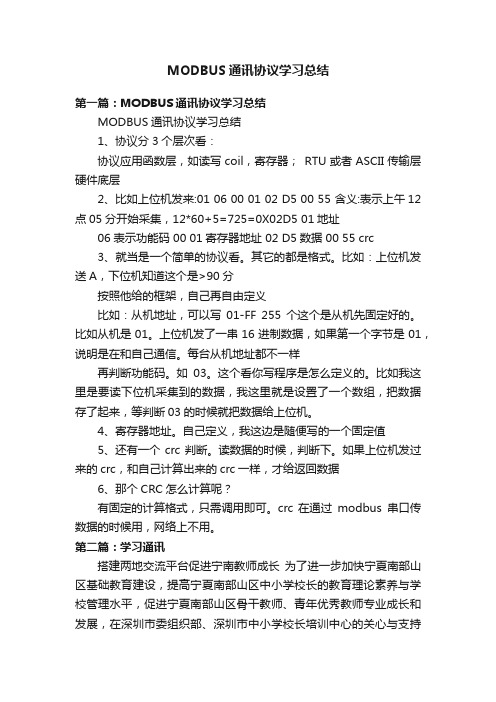
HLP_SV Modbus RTU 标准通讯协议格式通信资料格式Address Function Data CRC check8 bits 8 bits N×8bits 16bits1)Address通讯地址:1-2472)Function:命令码8-bit命令01 读线圈状态上位机发送数据格式:ADDRESS 01 ADDRH ADDRL NUMH NUML CRC注: ADDR: 00000 --- FFFF(ADDR=线圈地址-1);NUM: 0010-----0040 (NUM为要读线圈状态值的二进制数位数)正确时变频器返回数据格式:ADDRESS 01 BYTECOUNT DA TA1 DA TA2 DA TA3 DA TAN CRC注: BYTECOUNT:读取的字数错误时变频器返回数据格式:ADDRESS 0X81 Errornum CRC注: Errornum为错误类型代码如:要检测变频器的输出频率应发送数据:01 01 00 30 00 10 3D C9(16进制)变频器返回数据:01 01 02 00 20 B8 24(16进制)发送数据:0030hex(线圈地址49)返回的数据位为“0020”(16进制),高位与低位互换,为2000。
即输出频率为303(Max Ref)的50%。
关于2000对应50%,具体见图1。
03读保持寄存器上位机发送数据格式:ADDRESS 03 ADDRH ADDRL NUMH NUML CRC注:ADDR: 0 --- 0XFFFF;NUM: 0010-----0040 (NUM为要读取数据的字数)ADDR=Parameter Numbe r×10-1正确时变频器返回数据格式:ADDRESS 03 BYTECOUNT DA TA1 DA TA 2 DA TA 3 DA TAN CRC 注: BYTECOUNT:读取的字节数错误时变频器返回数据格式:ADDRESS 0X83 Errornum CRC如:要读变频器参数303的设定值应发送数据:01 03 0B D5 00 02 95 BC (16进制)Parameter 303(3029)=0BD5HEX变频器返回数据:“:”01 03 04 00 00 EA 60 B5 7B返回的数据位为“00 00 EA 60”(16进制)转换为10进制数为60000,表示303设置值为60.000※当参数值为双字时,NUM的值必须等于2。
sfere100通讯协议及异常处理
Sfere100通讯协议及异常处理5.1通讯仪表带有数字通讯接口,通过接口可以读取仪表的状态和测量值,也可以对仪表进行操作和参数设置。
仪表默认带有1路通讯接口,接口为RS-485,采用Modbus-RTU 协议。
可通过扩展通讯模块来增加1路通讯,具体情况见下表。
配置 模块代号 接口 协议标准配置 ――――― RS485接口 MODBUS-RTU C0RS485接口MODBUS-RTU扩展 通讯 模块 C1RS485接口Profibus-DP 通讯物理层1) RS485通讯接口,异步半双工模式;2) 通讯速度1200~19200bps 可设置,出厂默认为9600bps ;3)字节传送格式:1位起始位,8位数据位,1位校验位,1-2位停止位(N81/081/E81)可选;5.1.1通讯协议 MODBUS-RTU 5.1.1.1 MODBUS-RTU 概述MODBUS 协议只允许在主机(PC ,PLC 等)和从机(终端设备)之间通讯,而不允许独立的终端设备之间的数据交换,这样各终端设备不会在它们初始化时占据通讯线路,而仅限于响应到达本机的查询信号。
从机主机图5-1 查询应答周期图主机查询:查询消息帧包括从机地址码、功能代码、数据信息码、CRC 校验码。
地址码表明要选中的从机设备;功能代码告之被选中的从设备要执行何种功能;校验码用来检验一帧信息的正确性,为从设备提供了一种验证消息内容是否正确的方法,它采用CRC16校验。
从机响应:如果从机产生正常的响应,在响应消息中有从机地址码、功能代码、数据信息码和CRC 校验码。
数据信息码则包括了从设备收集的数据,如寄存器值或状态。
数据帧的结构:即报文格式。
地址码 功能码 数据码 校验码 1个字节 1个字节N 个字节2个字节地址码:是帧的开始部分,由一个字节(8位二进制代码)组成,十进制为0~255,在我们的系统中只使用1~247,其它地址保留。
这些位标明了用户指定的终端设备的地址,该设备将接收来自与之相连的主机数据。
MODBUS通讯协议学习总结
MODBUS通讯协议学习总结第一篇:MODBUS通讯协议学习总结MODBUS通讯协议学习总结1、协议分3个层次看:协议应用函数层,如读写coil,寄存器;RTU或者ASCII传输层硬件底层2、比如上位机发来:01 06 00 01 02 D5 00 55 含义:表示上午12点05分开始采集,12*60+5=725=0X02D5 01地址06表示功能码 00 01寄存器地址 02 D5数据 00 55 crc3、就当是一个简单的协议看。
其它的都是格式。
比如:上位机发送A,下位机知道这个是>90分按照他给的框架,自己再自由定义比如:从机地址,可以写01-FF 255个这个是从机先固定好的。
比如从机是01。
上位机发了一串16进制数据,如果第一个字节是01,说明是在和自己通信。
每台从机地址都不一样再判断功能码。
如03。
这个看你写程序是怎么定义的。
比如我这里是要读下位机采集到的数据,我这里就是设置了一个数组,把数据存了起来,等判断03的时候就把数据给上位机。
4、寄存器地址。
自己定义,我这边是随便写的一个固定值5、还有一个crc判断。
读数据的时候,判断下。
如果上位机发过来的crc,和自己计算出来的crc一样,才给返回数据6、那个CRC怎么计算呢?有固定的计算格式,只需调用即可。
crc 在通过modbus串口传数据的时候用,网络上不用。
第二篇:学习通讯搭建两地交流平台促进宁南教师成长为了进一步加快宁夏南部山区基础教育建设,提高宁夏南部山区中小学校长的教育理论素养与学校管理水平,促进宁夏南部山区骨干教师、青年优秀教师专业成长和发展,在深圳市委组织部、深圳市中小学校长培训中心的关心与支持下,在宁夏回族自治区固原市委组织部、固原市教育局精心组织安排下,宁夏回族自治区固原市2011年中小学校长、骨干教师、青年优秀教师(深圳)研修班于2011年11月23日在深圳市中小学校长培训中心(深圳城市学院)隆重开班了。
在开班典礼上,深圳市教育局副局长唐海海、宁夏回族自治区固原市教育局局长虎玉赟、副局长李志坚等做了重要讲话,宁夏回族自治区固原市中小学校长、骨干教师、优秀教师代表也做了表态发言。
丹佛斯变频器modbus通讯

丹佛斯变频器Modbus通讯济南创恒科技发展有限公司满建江∙FC系列变频器通过内置的RS485接口,以Modbus RTU格式进行通讯。
参数设置如表∙FC系列变频器需要设置的参数:8-01,控制地点,选择【2】控制字,或者【0】数字和控制字;8-02,控制来源,选择【1】RS 485;8-03,控制字超时时间;8-04,控制字超时功能,选择当控制字丢失,变频器采取的动作;8-30,【2】选择为Modbus RTU通讯协议;8-31,变频器的通讯地址,1-126范围内地址有效;8-32,设置通讯速度,各站速度要求一致;8-33,奇偶校验方式,各站要求设置一致;8-50,惯性停车的实现方式,当8-01选择为【0】时,请注意该参数。
丹佛斯变频器所要通讯的MODBUS地址为参数号码乘以10减去1,西门子PLC不需要减1. 例如:变频器的频率地址为3-10那么对应的MODBUS地址即是:(310×10)-1=3099(十进制)西门子200PLC 地址不需要减1 为43100在PLC的modbus指令块写入要通讯变频器地址,参数的地址,和参数的值后,即可更改此参数。
∙电报结构(十六进制)∙地址字段包含8位数据,有效的地址范围为0-247(十进制),0为广播模式;1-247对相应地址的从站进行寻址。
功能字段包含8位数据,有效地代码范围为1-FF,功能字段用于在主站和从站之间发送消息。
当从主站向从站发送时,功能字段为主站的控制字;当从从站向主站传送时,功能字段为从站的状态字。
∙数据字段,是由几组字节两个十六进制数字(00至FF)构成,根据不同的功能代码,数据字段包含的位长、作用不一,针对常用的功能代码,举例如下:∙1、功能代码=1,读取线圈状态∙ 2、功能代码=5,写入单个线圈数值∙ 3、功能代码=F,写入多个线圈数值∙线圈及位的意义。
地址0-31为主站写入用控制位,32-63为从站返回的状态位,如下表所示:∙例如,使电机启动并运转在50%*最大参考值的报文如下∙其中位的个数为 20H=32个位,也就是从00地址起始到31为止的位;字节数,是指写入数值为4个字节;写入数值 047C 对应00-16位,在传送时低位在前,因此为7C 04;2000 对应16-31位,50%*最大参考值,在传送时低位在前,因此为00 20;对于停止,应发043C代码4、功能代码=3,读取保持寄存器状态,保存寄存器保持2字节(即16位)∙ 5、功能代码=6,写入单个寄存器∙ 6、功能代码=10,写入多个寄存器数值∙寄存器列表:∙例如,当要读取3-41,加速时间时,需要写的报文:∙计算参数3-41的地址 3-41 → 341*10-1=3409 → D51(十六进制);保持寄存器状态都为双字节,因此在字个数位置应该为 2 ;正常情况下,变频器返回的报文为,∙012C 为读出的加速度时间,转换成十进制并考虑到控制单位,得到加速时间为3秒。
fc51通讯协议
关于丹佛斯变频器MODBUS RTU的通讯发布时间: 2008-11-18 12:03:40 被阅览数: 874 次一:MODBUS RTU规约概术MODBUS规约是MODICOM公司开发的一个为很多厂商支持的开放规约MODBUS 协议是应用于电子控制器上的一种通用语言。
通过此协议,控制器相互之间、控制器经由网络(例如以太网)和其它设备之间可以通信。
它已经成为一通用工业标准。
有了它,不同厂商生产的控制设备可以连成工业网络,进行集中监控。
此协议定义了一个控制器能认识使用的消息结构,而不管它们是经过何种网络进行通信的。
它描述了控制器请求访问其它设备的过程,如果回应来自其它设备的请求,以及怎样侦测错误并记录。
它制定了消息域格局和内容的公共格式。
二:丹佛斯MODBUS RTU概念DANFOSS 变频器在自动化领域中有着大量的应用,作为变频器专业供应商,DANFOSS 一直把提高产品的通信应用水平作为其重点工作之一。
基于MODBUS RTU协议,DANFOSS 开发了相应的控制集成卡,通过这种集成卡DANFOSS变频器可以以MODBUS RTU 协议方便与SCADA和HMI等设备集成在一起。
DANFOSS VLT2800或VLT5000(已停产)系列变频器MODBUS RTU通讯与FC300系列变频器的通讯类似三:S7-200、台达PLC与丹佛斯变频器接线:S7-200 DSUB9 DANFOSS3----+------------------688------------------------69台达PLC正信号+---------------------68负信号-----------------------69四:丹佛斯变频器的参数设置1.VLT5000(已停产)或VLT2800变频器相关通讯参数设置:561#---------2----RTU协议500#---------1----485地址为1501#---------5----9600570#---------0----1停止位,EVEN校验其他参数使用初始化参数2.FC300或FC51变频器相关通讯参数设置:8-30-----1----RTU协议8-31-----5----地址8-32----------波特率8-33----------1停止位,EVEN校验五:PLC的程序例子如果该变频器加了MCO305同步卡或PROFIBUS卡,此通讯功能被占用。
modbus-rtu协议入门讲解及RS-XZJ-100系列小主机兼容其他公司485设备的具体要求

Modbus-rtu协议入门讲解及RS-XZJ-100系列环境监控主机兼容其他公司485设备的具体要求1,字Word,字节byte, 位bit1Word=2byte(1个汉字=2个字节,1个英文=1个字节)1byte=8bit二进制(位)(比特)位是数据存储的最小单位2注意:编码8位二进制的解释:业内规定8位二进制(8bit)称为一个字节,二进制就是冯2进1,表示11111111,换算成10进制就是255,换算成16进制就是FF。
故一个字节表示16进制的最大表示到FF.8位数据位解释如下:即485组网中,主站问询以及设备应答帧结构,每一帧数据都是1个字节为单位体现的,而一个字节就是一个二进制的8位。
如下:主机问询帧结构:从机应答帧结构:从上方表格中可以看出主站问询及从站应答帧结构来看,都是以1个8位二进制即1个字节为单位传送的。
数据区:数据区是具体通讯数据,注意16bits数据高字节在前!解释如下:再解释何为高字节之前,需要了解所有帧结构中的数值都是16进制的。
举例说明一:1,假设485设备起始地址为3,我司环境监控主机作为485主站通过0x00 00号和0x00 01号寄存器读取该485设备数据主站问询0x00 00号和0x00 01号寄存器值从站应答帧(例如读到1号寄存器为65435,0号寄存器为658)上方表格中,主站问询了地址为3的485设备,3号功能码中0号和1号寄存器;485设备作出应答,3号设备3号功能码数据区应答了4个有效字节,数据区0号寄存器两个字节,数据区1号寄存器2个字节;从设备应答帧可以看出,485设备每个数据区寄存器是存了个16位的数据,即两个字节的数据,即16位二进制,1111111111111111,换算成10进制即是65535,也就是说每个寄存器最大存的10进制数是65535;以数据区0号寄存器为例,应答02 92两个字节,02在前,92在后,02这个字节就是高字节,带标数值的高位(个十百千万,万是高位,数值写在前方),即代表16进制的数值292,换算成10进制就是658。
汇川MD380系列变频器用户手册

MD380-高性能矢量变频器说明书前言前 言首先感谢您购买MD380系列变频器!MD380系列变频器与MD320系列应用场合一致,电机控制性能较MD320变频器有明显提高,并可实现异步电机和永磁同步机控制,增加了用户可编程功能及后台监控软件,支持多种PG卡,功能更强大。
本说明书介绍了如何正确使用MD380系列变频器。
在使用(安装、运行、维护、检查等)前,请务必认真阅读本使用说明书。
另外,请在理解产品的安全注意事项后再使用该产品。
注意事项●为了说明产品的细节部分,本说明书中的图例有时为卸下外罩或安全遮盖物的状态。
使用本产品时,请务必按规定装好外壳或遮盖物,并按照说明书的内容进行操作。
●本使用说明书中的图例仅为了说明,可能会与您订购的产品有所不同。
●由于产品升级或规格变更,以及为了提高说明书的便利性和准确性,本说明书的内容会及时进行变更。
●由于损坏或遗失而需要订购使用说明书时,请与本公司各区域代理商联系,或直接与本公司客户服务中心联系。
●如果您使用中仍有一些使用问题不明,请与本公司客户服务中心联系。
●全国统一服务电话:400-777-1260前言 MD380-高性能矢量变频器说明书简 介相对于MD320,MD380变频器主要在以下几个方面有明显提升:1)丰富的电压等级支持单相220V、三相220V、三相380V、三相480V、三相690V、三相1140V六个电压等级。
2)丰富的电机种类支持支持三相交流异步电机、三相交流永磁同步电机的矢量控制。
3)丰富的控制方式除有速度传感器矢量控制、无速度传感器矢量控制、V/F控制外,还支持V/F分离控制。
4)丰富的现场总线支持Modbus-RTU、Pro fi bus-DP、CANlink、CANopen四种总线。
5)丰富的编码器类型支持差分编码器、开路集电极编码器、旋转变压器、UVW编码器等。
6)全新的无速度传感器矢量控制算法全新的SVC(无速度传感器矢量控制)相比MD320变频器,带来更好的低速稳定性,更强的低频带载能力,而且支持SVC的转矩控制。
Modbus RTU相关常识和通信示例

Modbus RTU –基本功能1 关于ModBusModBus网络是一个工业通信系统,由带智能终端的可编程序控制器和计算机通过公用线路或局部专用线路连接而成。
其系统结构既包括硬件、亦包括软件。
它可应用于各种数据采集和过程监控。
1.1 报文结构以串行数据传输为基础,通过一位接着一位进行传送。
1.2协议数据单元(PDU)1.2.1 Modbus PDU(协议数据单元)由功能码和实际数据两部分组成。
1.2.2 Modbus 串行通讯的消息帧站号(站地址)站号字段为1字节长,可能选择0~247站点。
选择0 地址表示选择所有的子机站,代表广播消息的意思。
FC(RTU功能代码)FC字段为1字节长,用以下所示的0~255的值进行定义。
带有网格部分表示使用的FC。
请不要使用未使用的FC。
否则会成为异常应答。
常用ModBus的功能码FC定义如下:01 READ COIL STATUS 01 读取线圈状态02 READ INPUT STATUS 02 读取离散量输入。
03 READ HOLDING REGISTER 03 读取保持寄存器。
04 READ INPUT REGISTER 04 读取输入寄存器。
05 WRITE SINGLE COIL 05 强置单线圈。
06 WRITE SINGLE REGISTER 06 预置单寄存器15 WRITE MULTIPLE COIL 07 15 强置多线圈。
16 WRITE MULTIPLE REGISTER 16 预置多寄存器数据区数据字段包含所有的信息(功能代码(地址)、字节计数、数据数、数据等)。
有关各消息类型(广播、查询、正常应答、异常应答) 的信息字段的详细情况;CRC校验CRC-16 检查方式的2字节长数据。
由于信息字段的长度为可变,由FC和字节计数数据计算出在CRC-16代码的计算中所必要的帧长。
CRC-16计算的详情和算法请参照「CRC-16」。1.2.3 PDU消息类型–通讯过程一般工业设备中,消息类型有查询、正常应答、异常应答、广播4种。
丹佛斯FC100产品概述

FC102的软件特色
——电机自适应功能(AMA)
在静态时对主要电机进行测定: - 优化电机特性 - 提高启动特性 - 对不同的电机电缆线进行补偿 - 不需脱卸负载
2007-09-27
新一代 VLT® HVAC FC100变频器
Tao Yulong/HVAC/R 20
PDF created with pdfFactory trial version
FC102的硬件特色
用户所需的所有功能选件都可以在 工厂完成安装和测试 • 模块化设计理念 • 更好的可靠性 • 安装简便快速且成本更低
2007-09-27
新一代 VLT® HVAC FC100变频器
Tao Yulong/HVAC/R 8
PDF created with pdfFactory trial version
Tao Yulong/HVAC/R 13
PDF created with pdfFactory trial version
FC102的硬件特色
FC102 系列变频器集成了供热、通风、空调和自控系统所需的各种硬件特色: • 内置RFI 滤波器 • 内置双直流电抗器 • 双输入通道 PID 调节器 • USB,RS485 接口,标准内置MetasysN2, FLN Apogee和Modbus RTU,选件 BACnet MS/TP,LON Works,Profibus,DeviceNet • 两通道模拟量输入0-10V或0/4-20mA(可选) • 四通道输出信号( 1 模拟, 3 继电器 ) • 通用输入/输出选件,继电器选件 。。。
集成EMC滤波器 符合IEC 61800-3
控制单元 选件单元
可移式风扇便于清洁
2007-09-27
S7-300 Modbus RTU通讯方法(CP341作从站)_STEP

S7-300 Modbus RTU通讯方法(CP341作从站)_STEP 硬件及软件列表组态和配置编写通信程序设备连接手册下载硬件及软件列表设备名称设备型号PS 307 6ES7 307-1EA00-0AA0CPU 315-2DP 6ES7 315-2AG10-0AB0MMC 6ES7 953-8LG11-0AA0CP341 6ES7 341-1AH01-0AE0Dongle 6ES7 870-1AB01-0YA0应用CP341进行MODBUS协议通信时需要有Dongle的支持。
在使用之前先将Dongle 安装在CP341模块的背面的Dongle插槽中,Dongle和插入Dongle前后的CP341如下图所示:图1注意:STEP7 V5.X软件上,必须安装如下软件包才可进行后续的组态配置。
PTP协议软件包:SIMATIC S7-CP PtP Param V5.1+SP14MODBUS主站驱动MODBUS从站驱动组态和配置1、打开上面创建的项目ptp,用鼠标右键点击项目名称,选择Insert New Object-> SIMATIC 300 Station,更改站的名称为CP341 Modbus-S。
图22、双击Hardware进入硬件配置画面,插入RACK、CPU315-2DP、CP341。
图33、双击CP341模板,点击Parameter...,配置CP341参数。
在Protocol选项中选择MODBUS Slave。
图44、双击Protocol下的信封图标,配置MODBUS Slave参数,点击MODBUS-Slave按钮。
•步骤1:设置MODBUS从站地址,本例中设为2;•步骤2:设置MODBUS从站波特率,停止位,校验位等参数;•接下来配置功能代码所表示的参数,具体参见下4图5、FC01,05,15:读取、强制输出位的状态;左边的地址为信息传送地址,右边对应西门子的PLC地址区,即左边地址从0~100对应MODBUS地址区为00001~00101,对应西门子数据区为M0.0~M12.4;101~200对应MODBUS 地址区为00102~00201,对应西门子数据区为Q0.0~Q12.3;从地址201~300,301~400对应Modbus 地址区为00202~00301,00302~00401,对应西门子数据区为Timer,Counter。
fc51_modbus
Contents1. Safety5Safety Instructions5Approvals5General Warning5Avoid unintended Start6Before Commencing Repair Work62. Mechanical Installation7Before Starting7Mechanical Dimensions83. Electrical Installation9How to Connect9Electrical Installation in General9EMC-Correct Installation10Mains Connection11Motor Connection11Control Terminals12Connecting to Control Terminals13Switches13Power Circuit - Overview14Load sharing/Brake144. Programming15How to Programme15Programming with MCT-1015Programming with LCP 11 or LCP 1215Status Menu17Quick Menu17Quick Menu Parameters17Main Menu225. Modbus RTU23Modbus RTU Overview23Modbus RTU Message Framing Structure24Remote Terminal Unit24Modbus RTU Message Structure24Start/Stop Field24Address Field24Function Field25Data Field25CRC Check Field25 Coil/Register Addressing25 How to Control FC 5127 Function Codes Supported by Modbus RTU27 Exception and Error Codes27 How to Access Parameters28 Parameter Handling28 Storage of Data28 IND28 Text Blocks28 Conversion Factor28 Parameter Values28 Examples29 Read Coil Status (01HEX)29 Force/Write Single Coil (95HEX)29 Force/Write Multiple Coils (0F HEX)30 Read Holding Registers (03HEX)30 Preset Single Regiater (06HEX)31 Preset Multiple Registers (10HEX)32 Danfoss FC Control Profile32 Control Word According to FC Profile32 Explanation of the Control Bits33 Status Word According to FC Profile (STW)35 Explanation of the Status Bits35 Bus Speed Reference Value376. Parameter Overview390-** Operation/Display43 1-** Load/Motor44 2-** Brakes45 3-** Reference/Ramps46 4-** Limits/Warnings47 5-** Digital In/Out48 6-** Analog In/Out49 7-** Controllers50 8-** Comm. and Options51 13-** Smart Logic52 14-** Speical Functions53 15-** Drive Information54 16-** Data Readouts557. Troubleshooting578. Specifications59Mains Supply59 Other Specifications61 Special Conditions63 The Purpose of Derating63 Derating for Ambient Temperature63 Derating for Low Air Pressure63 Derating for Running at Low Speeds63 Options for VLT Micro Drive FC 5164Index6511.1.1.1.High Voltage WarningThe voltage of the frequency converter is dangerous whenever it is connected to mains. Incorrect installation of the motor or frequency converter may cause damage to the equipment, serious injury or death. Consequently, it is essential to comply with the instructions in this manual as well as local and national rules and safety regulations.1.1.2.Safety Instructions•Make sure the frequency converter is properly connected to earth.•Do not remove mains connections, motor connections or other power connections while the frequency converter is connected to power.•Protect users against supply voltage.•Protect the motor against overloading according to national and local regulations.•The earth leakage current exceeds 3.5 mA.•The [OFF] key is not a safety switch. It does not disconnect the frequency converter from mains.1.1.3.Approvals1.1.4.General WarningWarning:Touching the electrical parts may be fatal - even after the equipment has been disconnected from mains.Also make sure that other voltage inputs have been disconnected, (linkage of DC intermediate circuit).Be aware that there may be high voltage on the DC link even when the LEDs are turned off.Before touching any potentially live parts of the VLT Micro Drive, wait at least 4 minutes for all sizes.Shorter time is allowed only if indicated on the nameplate for the specific unit.Leakage CurrentThe earth leakage current from the VLT Micro Drive FC 51 exceeds 3.5 mA. According to IEC 61800-5-1 a reinforced Protective Earth connection must be ensured by means of a min. 10mm² Cu or an addtional PE wire - with the same cable cross section as the Mains wiring - must be terminated separately.Residual Current DeviceThis product can cause a D.C. current in the protective conductor. Where a residual current device (RCD) is used for extra protection,only an RCD of Type B (time delayed) shall be used on the supply side of this product. See also Danfoss Application Note on RCD, MN.90.GX.YY.Protective earthing of the VLT Micro Drive and the use of RCDs must always follow national and local regulations.Motor overload protection is possible by setting Parameter 1-90 Motor thermal protection to the value ETR trip. For the North American market: ETR functions provide class 20 motor overload protection, in accordance with NEC.VLT ® Micro Drive FC 51 Operating Instruc-tions1. Safety1Installation in high altitudes:By altitudes above 2km, please contact Danfoss Drives regarding PELV.1.1.5.IT MainsIT MainsInstallation on isolated mains source, i.e. IT mains.Max. supply voltage allowed when connected to mains: 440 V.As an option, Danfoss offers line filters for improved harmonics performance.1.1.6.Avoid unintended StartWhile the frequency converter is connected to mains, the motor can be started/stopped using digital commands, bus commands, references or via the Local Control Panel.•Disconnect the frequency converter from mains whenever personal safety considerations make it necessary to avoid unintended start of any motors.•To avoid unintended start, always activate the [OFF] key before changing parameters.1.1.7.Disposal InstructionEquipment containing electrical components must not be disposed of together with domestic waste.It must be separately collected with electrical and electronic waste according to local and currently valid leg-islation.1.1.8.Before Commencing Repair Work1.Disconnect FC 51 from mains (and external DC supply, if present.)2.Wait for 4 minutes for discharge of the DC-link.3.Disconnect DC bus terminals and brake terminals (if present)4.Remove motor cable1. SafetyVLT ® Micro Drive FC 51 Operating Instruc-tions12.2.1.Before Starting2.1.1.ChecklistWhen unpacking the frequency converter, make sure that the unit is un-damaged and complete. Check that the packaging contains the following:•VLT Micro Drive FC 51•Quick GuideOptional: LCP and/or de-coupling plate.Illustration 2.1: Content of box.2.2.Side-by-Side InstallationThe Danfoss VLT Micro Drive can be mounted side-by-side for IP 20 rating units and requires 100 mm clearance above and below for cooling. Regarding surroundings in general, please see chapter 7. Specifications.Illustration 2.2: Side-by-side installation.VLT ® Micro Drive FC 51 Operating Instruc-tions2. Mechanical Installation22.3.1.Mechanical DimensionsIllustration 2.3: Mechanical dimensions.NB!A template for drilling can be found on the flap of the packaging.1) For LCP with potentiometer, please add 7.6 mm.2 These dimensions will be announced at a later point.NB!DIN rail mounting kit is available for M1. Please use ordering number 132B01112. Mechanical InstallationVLT ® Micro Drive FC 51 Operating Instruc-tions23.3.1.How to Connect3.1.1.Electrical Installation in GeneralNB!All cabling must comply with national and local regulations on cable cross-sections and ambient temperature. Copper conductors required, (60-75° C) recommended.Table 3.1: Tightening of terminals.3.1.2.FusesBranch circuit protection:In order to protect the installation against electrical and fire hazard, all branch circuits in an installation, switch gear, machines etc., must be short-circuited and overcurrent protected according to national/international regulations.Short circuit protection:Danfoss recommends using the fuses mentioned in the following tables to protect service personnel or other equipment in case of an internal failure in the unit or short-circuit on DC-link. The frequency converter provides full short circuit protection in case of a short-circuit on the motor or brake output.Overcurrent protection:Provide overload protection to avoid overheating of the cables in the installation. Overcurrent protection must always be carried out according to national regulations. Fuses must be designed for protection in a circuit capable of supplying a maximum of 100,000 A rms (symmetrical), 480 V maximum.NonUL compliance:If UL/cUL is not to be complied with, Danfoss recommends using the fuses mentioned in table 1.3, which will ensure compliance with EN50178:In case of malfunction, not following the fuse recommendation may result in damage to the frequency converter.VLT ® Micro Drive FC 51 Operating Instruc-tions3. Electrical Installation3Table 3.2: Fuses3.1.3.EMC-Correct InstallationFollowing these guidelines is advised, where compliance with EN 61000-6-3/4, EN 55011 or EN 61800-3 First environment is required. If the installation is in EN 61800-3 Second environment , then it is acceptable to deviate from these guidelines. It is however not recommended.Good engineering practice to ensure EMC-correct electrical installation:•Use only braided screened/armoured motor cables and control cables.The screen should provide a minimum coverage of 80%.The screen material must be metal, not limited to but typically copper, aluminium, steel or lead. There are no special requirements for the mains cable.•Installations using rigid metal conduits are not required to use screened cable, but the motor cable must be installed in conduit separate from the control and mains cables. Full connection of the conduit from the drive to the motor is required. The EMC performance of flexible conduits varies a lot and information from the manufacturer must be obtained.•Connect the screen/armour/conduit to earth at both ends for motor cables and control cables.•Avoid terminating the screen/armour with twisted ends (pigtails). Such a termination increases the high frequency impedance of the screen,which reduces its effectiveness at high frequencies. Use low impedance cable clamps or glands instead.•Ensure good electrical contact between the de-coupling plate and the metal chassis of the frequency converter, see Instruction MI.02.BX.YY •Avoid using unscreened/unarmoured motor or control cables inside cabinets housing the drive(s), where possible.3. Electrical InstallationVLT ® Micro Drive FC 51 Operating Instruc-tions33.2.Mains Connection3.2.1.Connecting to MainsStep 1: First mount earth cable.Step 2: Mount wires in terminals L1/L, L2 and L3/N and tighten.Illustration 3.1: Mounting of earth cable and mains wires.For 3-phase connection, connect wires to all three terminals.For single-phase connection, connect wires to terminals L1/L and L3/N.Illustration 3.2: Three-phase and single-phase wire connec-tions.3.3.Motor Connection3.3.1.How to Connect the MotorSee the chapter Specifications for correct dimensioning of motor cable cross-section and length.•Use a shielded/armored motor cable to comply with EMC emission specifications, and connect this cable to both the decoupling plate and the motor metal.•Keep motor cable as short as possible to reduce the noise level and leakage currents.For further details on mounting of the decoupling plate, please see instruction MI.02.BX.YY.All types of three-phased asynchronous standard motors can be connec-ted to the frequency converter. Normally, small motors are star-connec-ted (230/400 V, Δ/Y). Large motors are delta-connected (400/690 V, Δ/Y). Refer to motor nameplate for correct connection and voltage.Illustration 3.3: Star and delta connections.VLT ® Micro Drive FC 51 Operating Instruc-tions3. Electrical Installation3Step 1: First, mount the earth cable.Step 2: Connect wires to terminals either in star or delta-connection. Seemotor nameplate for further information.Illustration 3.4: Mounting of earth cable and motor wires.For EMC correct installation, use optional de-coupling plate, see chapter Options for VLT Micro Drive FC 51.Illustration 3.5: VLT Micro Drive with de-coupling plate 3.4.Control Terminals3.4.1.Access to Control TerminalsAll control cable terminals are located underneath the terminal cover infront of the frequency converter. Remove the terminal cover using ascrewdriver.Illustration 3.6: Removing terminal cover.NB!See back of terminal cover for outlines of control terminals and switches.3. Electrical InstallationVLT® Micro Drive FC 51 Operating Instruc-tions 33.4.2.Connecting to Control TerminalsThis illustration shows all control terminals of the VLT Micro Drive. Applying Start (term. 18) and an analog reference (term. 53 or 60) make the frequencyconverter run.Illustration 3.7: Overview of control terminals in PNP-configuration and factory setting.3.5.SwitchesNB!Do not operate switches with power on the frequency converter.Bus termination:Switch BUS TER pos. ON terminates the RS485 port, terminals 68, 69.See power circuit drawing.Default setting = Off.Illustration 3.8: S640 Bus termination.S200 Switches 1-4:Table 3.3: Settings for S200 Switches 1-4Illustration 3.9: S200 Switches 1-4.NB!Parameter 6-19 must be set according to Switch 4 po-sition.VLT ® Micro Drive FC 51 Operating Instruc-tions3. Electrical Installation33.6.Power Circuit - Overview3.6.1.Power Circuit - OverviewIllustration 3.10: Diagram showing all electrical terminals.Brake not applicable for frame M1.Brake resistors are available from Danfoss.Improved power factor and EMC performance can be achieved by installing optional Danfoss line filters.Danfoss power filters can also be used for load sharing.3.6.2.Load sharing/BrakeUse 6.3 mm insulated Faston Plugs designed for high voltage for DC (Load Sharing and brake).Contact Danfoss or see instruction no. MI.50.Nx.02 for load sharing and instruction no. MI.90.Fx.02 for brake.Load sharing: Connect terminals UDC- and UDC/BR+.Brake: Connect terminals BR- and UDC/BR+.Note that voltage levels of up to 850 V DC may occur between terminalsUDC+/BR+ and UDC-. Not short circuit protected.3. Electrical InstallationVLT ® Micro Drive FC 51 Operating Instruc-tions34.4.1.How to Programme4.1.1.Programming with MCT-10The frequency converter can be programmed from a PC via RS485 com-port by installing the MCT-10 Set-up Software.This software can either be ordered using code number 130B1000 or downloaded from the Danfoss Web site: , Business Area: Motion Controls.Please refer to manual MG.10.RX.YY.4.1.2.Programming with LCP 11 or LCP 12The LCP is divided into four functional groups:1.Numeric display.2.Menu key.3.Navigation keys.4.Operation keys and indicator lights (LEDs).Illustration 4.1: LCP 12 with potentiometerIllustration 4.2: LCP 11 without potentiometerThe display:A number of information can be read from the display.Set-up number shows the active set-up and the edit set-up. If the same set-up acts as both active and edit set-up, only that set-up number is shown (factory setting).When active and edit set-up differ, both numbers are shown in the display(Setup 12). The number flashing, indicates the edit set-up.Illustration 4.3: Indicating Set-upVLT ® Micro Drive FC 51 Operating Instruc-tions4. Programming4The small digits to the left are the selected parameter number.Illustration 4.4: Indicating selected par. no.The large digits in the middle of the display show the value of theselected parameter.Illustration 4.5: Indicating value of selected par.The right side of the display shows the unit of the selected parameter.This can be either Hz, A, V, kW, HP, %, s or RPM.Illustration 4.6: Indicating unit of selected par.Motor direction is shown to the bottom left of the display - indicatedby a small arrow pointing either clockwise or counterclockwise.Illustration 4.7: Indicating motor directionUse the [MENU] key to select one of the following menus:Status Menu:The Status Menu is either in Readout Mode or Hand on Mode . In Readout Mode the value of the currently selected readout parameter is shown in the display.In Hand on Mode the local LCP reference is displayed.Quick Menu:Displays Quick Menu parameters and their settings. Parameters in the Quick Menu can be accessed and edited from here. Most applications can be run by setting the parameters in the Quick Menus.Main Menu:Displays Main Menu parameters and their settings. All parameters can be accessed and edited here. A parameter overview is found later in this chapter.Indicator lights:•Green LED: Power is on the frequency converter.•Yellow LED: Indicates a warning.•Flashing red LED: Indicates an alarm.4. ProgrammingVLT ® Micro Drive FC 51 Operating Instruc-tions4Navigation Keys:[Back]: For moving to the previous step or layer in the navigation structure.Arrows [▲] [▼]: For manoeuvring between parameter groups, parameters and within parameters.[OK]: For selecting a parameter and for accepting changes to parameter settings.Operation Keys:A yellow light above the operation keys indicates the active key.[Hand on]: Starts the motor and enables control of the frequency converter via the LCP.[Off/Reset]: The motor stops except in alarm mode. In that case the motor will be reset.[Auto on]: The frequency converter is controlled either via control terminals or serial communication.[Potentiometer] (LCP12): The potentiometer works in two ways depending on the mode in which the frequency converter is running.In Auto Mode the potentiometer acts as an extra programmable analog input.In Hand on Mode the potentiometer controls local reference.4.2.Status MenuAfter power up the Status Menu is active. Use the [MENU] key to toggle between Status, Quick Menu and Main Menu.Arrows [▲] and [▼] toggles between the choices in each menu.The display indicates the status mode with a small arrow above “Status”.Illustration 4.8: Indicating Status mode4.3.Quick MenuThe Quick Menu gives easy access to the most frequently used parameters.1.To enter the Quick Menu, press [MENU] key until indicator in display is placed above Quick Menu , then press [OK].e [▲] [▼] to browse through the parameters in the Quick Menu.3.Press [OK] to select a parameter.e [▲] [▼] to change the value of a parameter setting.5.Press [OK] to accept the change.6.To exit, press either [Back] twice to enter Status , or press [Menu] once to enter Main Menu.Illustration 4.9: Indicating Quick Menu mode4.4.Quick Menu Parameters4.4.1.Quick Menu Parameters - Basic Settings QM1Below are descriptions of all parameters found in the Quick Menu.* = Factory setting.Option:Function:Enter motor power from nameplate data.Two sizes down, one size up from nominal VLT rating.[1]0.09 kW/0.12 HPVLT ® Micro Drive FC 51 Operating Instruc-tions4. Programming4[2]0.12 kW/0.16 HP [3]0.18kW/0.25 HP [4]0.25 kW/0.33 HP [5]0.37kW/0.50 HP [6]0.55 kW/0.75 HP [7]0.75 kW/1.00 HP [8] 1.10 kW/1.50 HP [9] 1.50 kW/2.00 HP [10]2.20 kW/3.00 HP [11] 3.00 kW/4.00 HP [12] 3.70 kW/5.00 HP [13] 4.00 kW/5.40 HP [14] 5.50 kW/7.50 HP [15]7.50 HP/10.0 HP [16]11.00 kW/15.00 HpNB!Changing this parameter affects par. 1-22 to 1-25, 1-30, 1-33 and 1-35.m.n )Range:Function:230/400 V [50 - 999 V]Enter motor voltage from nameplate data.m.n )Range:Function:50 Hz * [20-400 Hz]Enter motor frequency from nameplate data.m.n )Range:Function:M-type dependent * [0.01 - 26.00A]Enter motor current from nameplate data.m.n )Range:Function:M-type Dependent * [100 - 9999RPM]Enter motor nominal speed from nameplate data.Option:Function:Use AMT to optimize motor performance.NB!This parameter cannot be changed while motor runs.1.Stop VLT – make sure motor is at standstill2.Choose [2] Enable AMT3.Apply start signal – Via LCP: Press Hand On- Or in Remote On mode: Apply start signal on terminal 184. ProgrammingVLT ® Micro Drive FC 51 Operating Instruc-tions4[0] *Off AMT function is disabled.[2]Enable AMTAMT function starts running.NB!To gain optimum tuning of frequency converter, run AMT on a cold motor.Range:Function:0.00* [-4999 - 4999]Enter value for minimum reference.The sum of all internal and external references are clamped (limited) to the minimum reference value, par. 3-02.Range:Function:Maximum Reference is adjustable in the range Minimum Reference - 4999.50.00* [-4999 - 4999]Enter value for Maximum Reference.The sum of all internal and external references are clamped (limited) to the maximum reference value, par.3-03.Range:Function:3.00 s * [0.05 - 3600 s ]Enter ramp-up time from 0 Hz to rated motor frequency (f M,N ) set in par. 1-23.Choose a ramp-up time ensuring that torque limit is not exceeded, see par. 4-16.Range:Function:3.00* [0.05 - 3600 s]Enter ramp down time from rated motor frequency (f M,N ) in par. 1-23 to 0 Hz.Choose a ramp down time that does not cause over-voltage in inverter due to regenerative operation of motor.Furthermore, regenerative torque must not exceed limit set in par. 4-17.4.4.2.Quick Menu Parameters - PI Basic Settings QM2The following is a brief description of the parameters for the PI Basic Settings. For a more detailed description, please see VLT Micro Drive ProgrammingGuide , MG.02.CX.YY.Range:Function:[]Choose [3] Process Closed LoopRange:Function:[-4999 - 4999]Sets limits for set-point and feedback.Range:Function:[-4999 - 4999]Sets limits for set-point and feedback.Range:Function:[-100.00 - 100.00]Preset [0] works as set-point.Range:Function:[0.0 - 400 Hz]Lowest possible output frequency.VLT ® Micro Drive FC 51 Operating Instruc-tions4. Programming4Range:Function:[0.0 - 400.00 Hz]Highest possible output frequency.NB!Default 65 Hz should normally be reduced to 50 - 55 Hz.Range:Function:[0.00 - 19.99 mA]Normally set to 0 or 4 mA.Range:Function:[0.01 - 20.00 mA]Normally (default) set to 20 mA.Range:Function:[-4999 - 4999]Value corresponding to P. 6-22 setting.Range:Function:[-4999 - 4999]Value corresponding to P. 6-23 setting.Range:Function:[0.01 - 10.00 s]Noise suppressing filter.Range:Function:[]Choose [2] analog input 60.Range:Function:[]Most PI controllers are “Normal”.Range:Function:[]Leave Enabled normally.Range:Function:[0.0 - 200.0 Hz]Choose expected normal running speed.Range:Function:[0.00 - 10.00]Enter the P-factor.Range:Function:[0.10 - 9999.00 s]Enter the I-factor.4. ProgrammingVLT ® Micro Drive FC 51 Operating Instruc-tions4Range:Function:[0 - 400%]Only applicable with changing set-points.44.5.Main MenuThe Main Menu gives access to all parameters.1.To enter the Main Menu, press [MENU] key until indicator indisplay is placed above Main Menu.e [▲] [▼] to browse through the parameter groups.3.Press [OK] to select a parameter group.e [▲] [▼] to browse through the parameters in the specificgroup.5.Press [OK] to select the parameter.e [▲] [▼] to set/change the parameter value.7.Press [OK] to accept the value.8.To exit, press either [Back] twice to enter Quick Menu, or press[Menu] once to enter Status.Illustration 4.10: Indicating Main Menu mode45.5.1.Modbus RTU Overview5.1.1.AssumptionsThese operating instructions assume that the installed controller supports the interfaces in this document and that all the requirements stipulated in the controller, as well as the frequency converter, are strictly observed, along with all limitations therein.5.1.2.What the User Should Already KnowThe Modbus RTU (Remote Terminal Unit) is designed to communicate with any controller that supports the interfaces defined in this document. It is assumed that the user has full knowledge of the capabilities and limitations of the controller.5.1.3.Modbus RTU OverviewRegardless of the type of physical communication networks, the Modbus RTU Overview describes the process a controller uses to request access to another device. This includes i.a. how it will respond to requests from another device, and how errors will be detected and reported. It also establishes a common format for the layout and contents of message fields.During communications over a Modbus RTU network, the protocol determines how each controller will learn its device address, recognise a message addressed to it, determine the kind of action to be taken, and extract any data or other information contained in the message. If a reply is required, the controller will construct the reply message and send it.Controllers communicate using a master-slave technique in which only one device (the master) can initiate transactions (called queries). The other devices (slaves) respond by supplying the requested data to the master, or by taking the action requested in the query.The master can address individual slaves, or can initiate a broadcast message to all slaves. Slaves return a message (called a response) to queries that are addressed to them individually. No responses are returned to broadcast queries from the master. The Modbus RTU protocol establishes the format for the master’s query by placing into it the device (or broadcast) address, a function code defining the requested action, any data to be sent, and an error-checking field. The slave’s response message is also constructed using Modbus protocol. It contains fields confirming the action taken, any data to be returned, and an error-checking field. If an error occurs in receipt of the message, or if the slave is unable to perform the requested action, the slave will construct an error message and send it in response, or a time-out will occur.5.1.4.Frequency Converter with Modbus RTUThe frequency converter communicates in Modbus RTU format over the built-in RS-485 interface. Modbus RTU provides access to the Control Word and Bus Reference of the frequency converter.The Control Word allows the Modbus master to control several important functions of the frequency converter:•Start•Stop of the frequency converter in various ways:Coast stop Quick stop DC Brake stop Normal (ramp) stop •Reset after a fault trip•Run at a variety of preset speeds •Run in reverse•Change the active set-up•Control the frequency converter’s two built-in relaysThe Bus Reference is commonly used for speed control. It is also possible to access the parameters, read their values, and where possible, write values to them. This permits a range of control options, including controlling the setpoint of the frequency converter when its internal PID controller is used.55.2.Modbus RTU Message Framing Structure5.2.1.Remote Terminal UnitThe controllers are set up to communicate on the Modbus network using RTU (Remote Terminal Unit) mode, with each 8-bit byte in a message containing two 4-bit hexadecimal characters.The format for each byte is shown below.Start bit Data bit Stop/pari-ty Stop5.2.2.Modbus RTU Message StructureThe transmitting device places a Modbus RTU message into a frame with a known beginning and ending point. This allows receiving devices to begin at the start of the message, read the address portion, determine which device is addressed (or all devices, if the message is broadcast), and to recognise when the message is completed. Partial messages are detected and errors set as a result - or timeouts occur. Characters for transmission must be in hexadecimal 00 to FF format in each field.The frequency converter continuously monitors the network bus, also during “silent” intervals. When the first field (the address field) is received, each frequency converter or device decodes it to determine which device is being addressed. Modbus RTU messages addressed to zero are broadcast messages.No response is permitted for boradcast messages. A typical message frame is shown below.StartAddress Function Data CRC check End T1-T2-T3-T41 byte1 byteN x 1 byte2 bytesT1-T2-T3-T4Table 5.1: Typical Modbus RTU Message Structure5.2.3.Start/Stop FieldMessages start with a silent period of at least 3.5 character intervals. This is implemented as a multiple of character intervals at the selected network baud rate (shown as Start T1-T2-T3-T4). The first field to be transmitted is the device address. Following the last transmitted character, a similar period of at least 3.5 character intervals marks the end of the message. A new message can begin after this period.The entire message frame must be transmitted as a continuous stream. If a silent period of more than 1.5 character intervals occurs before completion of the frame, the receiving device flushes the incomplete message and assumes that the next byte will be the address field of a new message. Similarly,if a new message begins prior to 3.5 character intervals after a previous message, the receiving device will ignore both messages. This will cause a time-out (no response from the slave).5.2.4.Address FieldThe address field of a message frame contains 1 byte. Valid slave device addresses are in the range of 0 - 247 decimal. The individual slave devices are assigned addresses in the range of 1 - 247 (0 is reserved for broadcast mode, which all slaves recognise). A master addresses a slave by placing the slave address in the address field of the message.5。
CT100说明书0310

-3-
CT100 系列变频器手册
第二章 产品信息
第二章 产品信息
2.1 产品型号命名规则及铭牌
2.1.1 命名规则 产品铭牌上的字母、数字组合分别表示了产品所属系列、适用电源、功率、适用负载类
型Hale Waihona Puke 。CT100 - 4T - 7.5G/11P - B
①:产品类型 CT100 通用矢量变频器
②:电压等级 2 220Vac 4 380Vac 6 660Vac
③:电压类型 S 单相输入 T 三相输入
⑤ :制动单元 B 内置制动单元 无 无内置制动单元
④ :功率等级 G/无 恒转矩负载/重载
P 变转矩负载/轻载
7.5 7.5KW 11 11KW
图 2-1 产品命名规则
2.1.2 产品铭牌
图 2-2 产品铭牌 -4-
CT100 系列变频器手册 2.2 产品规格型号及技术参数 2.2.1 产品规格型号表
-1-
CT100 系列变频器手册 1.1.3 配线时
第一章 安全注意事项
危险
》 必须具有专业资格的人员进行配线作业,否则有触电或产品损坏的危险。 》 配线时必须严格按照本手册执行,否则有触电或产品损坏的危险。 》 必须确认输入电源完全断开的情况下,方能进行配电作业,否则有触电的危险。 》 所用到的电线和断路器、接触器等必须按手册要求选用国标产品。 》 变频器必须可靠接地,否则有触电的危险。 》 严格按照变频器上的丝印配线,禁止将输入、输出接反,否则有损坏设备的危险。
FM100-2系列表计通讯规约100810

FM100-2 智能测控装置通讯规约深圳市华力特电气股份有限公司版权所有不得复制目录1 引言 (2)2 ModBus基本规则 (2)3 数据帧格式 (2)4信息帧格式 (3)4.1 地址码(ADD) (4)4.2 功能码(CS) (4)4.3 数据区(DATA): (5)4.4 错误校验码(CRC): (6)5 信息帧格式举例 (7)5.1 功能码03 (7)5.2 功能码06 (8)5.3 功能码10 (9)5.4 出错处理 (11)6 FM100-2系列各型号通讯信息表 (12)6.1 数据变换 (12)6.2 FM100-2A (13)6.3 FM100-2B (17)6.4 FM100-2C (21)6.5 FM100-2D (27)6.6 FM100-2E (33)1 引言FM100-2系列智能测控装置采用国际标准的MODBUS-RTU 通讯协议,可与施耐德、西门子、AB 、GE 、Modicon 等多个国际著名品牌的可编程顺序控制器(PLC)、SCADA,DCS 或第三方具有ModBus 兼容的监控系统之间进行信息和数据的有效传递。
本通讯规约详细描述了本机串行口通讯的读、写命令格式及内部信息数据的定义,以便第三方开发使用。
2 ModBus 基本规则➢ 所有RS485通讯回路都应遵照主/从方式。
依照这种方式,数据可以在一个主站(如:PC)和最多32个从站(如:FM100-2系列智能测控装置)之间传递。
➢ 主站将初始化和控制在RS485通讯回路上传递的所有信息。
➢ 通讯的发起方只能为主站,不能为从站。
➢ 所有RS485总线上的通信都以“信息帧”(报文)方式发生。
“信息帧”就是一个由数据帧(每一个字节为一个数据帧)构成的字符串(最多255个字节),是由信息头和发送的编码数据构成的标准异步串行数据。
➢ 如果主站或子站接收到含有未知命令的信息帧,则不予以响应。
➢ 任何情况从站只能响应主站一个请求。
西门子PLCs7-1200modbus-tcp通信实例编程详细指导

西门⼦PLCs7-1200modbus-tcp通信实例编程详细指导西门⼦S7-1200 Modbus-TCP通信例⼦【】绝密【】NDA【X】公开⼀、组⽹概述本⽂以 ZKA-4488-ETH 为例介绍西门⼦PLC与深圳市综科智控科技开发有限公司的IO设备进⾏Modbus通讯的步骤设置。
ZKA-4488-ETH 是 8 路数字量输⼊(DI),8 路数字量输出(DO),4路模拟量输⼊(AI,0/4-20mA),4 路模拟量输出设备(AO,0/4-20mA),以太⽹通信。
以 ZKA-4488-ETH 为例,出⼚默认通讯参数如下:ZK模块 IP 为:192.168.0.105TCP 端⼝为:10001(注意:我们模块出⼚时默认端⼝为10001,客户也可以通过ZK模块的配置⽂件把ZK通讯端⼝改成modbus-tcp的默认端⼝502)⼯作模式为:服务器模式⼆、S7-200 Modbus TCP通信1 S7-200 Modbus T CP 通信简介Modbus 是公开通信协议,详细的协议和规范,请访问Modbus 组织的⽹站:/S7-1200 CPU 本体上集成了⼀个 PROFINET 通信⼝,⽀持以太⽹和基于TCP/IP和UDP 的通信标准。
这个PROFINET 物理接⼝是⽀持10/100Mb/s的 RJ45⼝,⽀持电缆交叉⾃适应,因此⼀个标准的或是交叉的以太⽹线都可以⽤于这个接⼝。
使⽤这个通信⼝可以实现 S7-1200 CPU 与编程设备的通信,与HMI触摸屏的通信,以及与其它 CPU 之间的通信,S7-1200 CPU 的PROFINET 通信⼝主要⽀持以下通信协议及服务Profinet IO (V2.0开始)S7 通信(V2.0开始⽀持客户端)TCPISO on TCPUDP(V2.0开始)Modbus TCPHMI通信Web通信(V2.0开始)。
硬件版本V4.1 ⽀持的协议和最⼤的连接资源:S7-1200的连接资源分配给每个类别的预留连接资源数为固定值;您⽆法更改这些值。
MODBUS RTU规约

概述:本规约采用Modbus规约RTU模式,可以方便地与多种组态软件相连接,其通讯驱动与Modicon Modbus_RTU格式完全兼容。
1、字节格式:每字节含8位二进制码,传输时加上一个起始位(0),一个停止位(1),共10位。
其传输序列如上图所示,D0是字节的最低有效位,D7是字节的最高有效位。
先传低位,后传高位。
2、通讯数据格式:通讯时数据以字(WORD— 2字节)的形式回送,回送的每个字中,高字节在前,低字节在后,如果2个字连续回送(如:浮点或长整形),则高字在前,低字在后。
数据类型寄存器数字节数说明字节数据 1 1整形数据 1 2一次送回,高字节在前,低字节在后长整形数浮点数据2 4分两个字回送,高字在前,低字在后3、帧格式:3.1读取仪表寄存器内容(功能码 03H)3.1.1上位机发送的帧格式:顺序代码示例说明1 仪表地址 1 仪表的通讯地址(1-255之间)2 03H 03H 功能码3 起始寄存器地址高字节10H4 起始寄存器地址低字节00H寄存器起始地址5 寄存器个数高字节00H6 寄存器个数低字节02H寄存器个数7 CRC16 校验高字节C0H8 CRC16 校验低字节CBHCRC 校验数据3.1.2仪表回送的帧格式(数据正常)顺序代码说明1 仪表地址仪表的通讯地址(1-255之间)2 03H 功能码3 回送数据域字节数(M)4 第一个寄存器数据…………第N个寄存器数据M+4 CRC 校验高字节M+5 CRC 校验低字节3.1.3如果起始寄存器地址或寄存器个数错误,仪表回送:顺序代码示例说明1 仪表地址 1 仪表的通讯地址(1-255之间)2 83H 83H 功能码3 02H 02H 错误代码4 CRC 校验高字节C0H5 CRC校验低字节F1H3.2设置仪表寄存器内容(功能码 16H或10H或06H)3.2.1.1 功能码06H写单路,将一个字(2字节)数据写入仪表寄存器中,上位机发送的帧格式:顺序代码示例说明1 仪表地址 1 仪表的通讯地址(1-255之间)2 06H 06H 功能码3 寄存器地址高字节10H寄存器地址1000H4 寄存器地址低字节00H5 写入数据高字节00H写入数据0CH6 写入数据低字节0CH7 CRC校验高字节8DHCRC校验数据8D0FH8 CRC校验低字节0FH3.2.1.2 仪表回送:如果写入正确,则仪表回送相同的数据。
丹佛斯FC51与PLC及HMI通讯介绍

关于丹佛斯FC51通讯的部分介绍前言丹佛斯FC51系列变频器通讯:硬件集成485通讯口(两线制);软件上集成两种通讯协议FC协议(丹佛斯自行研制)和MODBUS RTU协议(国际标准通讯协议),本文主要对于FC51变频器MODBUS RTU通讯协议上面做相关介绍。
关键词丹佛斯FC51 通讯MODBUS协议关于MODBUS通讯协议丹佛斯FC51通讯设定参数8-30 设为2 通讯协议为MODBUS协议8-31 设为1 通讯子机地址, 设置为28-32 设为2 通讯波特率为9600,设置为3,192008-33 设为0 通讯数据格式8,E,1,设置为2,8N1此通讯主要介绍写频率读电压读电流读输出频率丹佛斯FC51通讯设定参数8-30 设为2 通讯协议为MODBUS协议8-31 设为1 通讯子机地址8-32 设为2 通讯波特率为96008-33 设为0 通讯数据格式8,E,13-02 频率参考值(MIN)* 设置为03-03 频率参考值(MAX)* 设置为100hz注*:变频器频率通过通讯设定的是百分比(P),实际设定的频率就是(MAX-MIN)×P÷10000(P的设定有两个小数位)此通讯主要介绍写频率读输出电压读输出电流读输出频率1,变频器MODBUS地址的定义丹佛斯变频器所要通讯的MODBUS地址为参数号码乘以10减去1例如:变频器的频率地址为3-10那么对应的MODBUS地址即是:(310×10)-1=3099(十进制)16进制为0C1B2,读写变频器的操作(1)写频率命令代码:01 06 0C 1B ** ** CRC则变频器返回代码为:01 06 0C 1B ** ** CRC其中:01 代表变频器地址一个字节06 代表MODBUS写功能码一个字节0C 1B 代表变频器内部MODBUS地址两个字节,要写入的频率地址** ** 代表所要写的频率的百分比两个字节CRC 代表冗余校验码两个字节其中低位在前高位在后(2)读电机参数参数为:16-12 电机运行电压对应MODUBS地址为(1612×10)-1=3EF716-13 读电机运行频率对应MODUBS地址为(1613×10)-1=3F0116-14 电机运行电流对应MODUBS地址为(1614×10)-1=3F0B命令代码:01 03 3E F7 00 01 CRC则变频器返回:01 03 3E F7 00 02 ** ** CRC其中:01 代表变频器地址一个字节03 代表MODBUS读功能码一个字节3E F7 代表变频器内部MODBUS地址两个字节(电压地址)00 01 代表读一个字两个字节CRC 代表冗余校验码两个字节其中低位在前高位在后00 02 代表返回2个字节两个字节** ** 代表返回的电压值两个字节3,启动/停止变频器写047C (10进制是1148)到地址50000-1=49999(HC34F)启动变频器地址不减1时为047C写043C (10进制是1184) 到地址50000-1=49999(HC34F)停止变频器地址不减1时为043C3-10的八段速每段速的设定,需要在K8里面写相应的地址号0-7八段速设定里面当K8厘米的值等于0时为0段速,当K8里的值等于1时为第一段速,依此类推,当K8的值等于7时为第7段速读变频器状态(根据地址算法:参数号乘以10,前面加4 )读取参数16-90和16-92 (在编程指南44页)。
基于MODBUS_RTU协议的PLC多路数据采集系统

2) PL C 控 制 与 显 示 层 涉 及 PL C 控 制 设 备 ADAM25510 E/ TCP 和显示屏 ,ADAM25510 E/ TCP 通过 ADAM25510 Series Utilit y 软件平台与工作主 机通信 ,实现嵌入式编程 。采用串口 1 接口与显示 屏连接 ,通过 ADAM 输入/ 输出模块和串口 2 控制 各传感器 ,采用 RJ245 网络口与上位机通信并存储 数据信息 。
4) COM4 ( RS2232/ RS2485) 为保留端口 。 设计实现如图 1 所示 。
器 ,然后通过程序按 MODBU S2R TU 通信协议发送 垂询指令 ,观察响应数据情况 。程序中关键的一步 是输入十六进制指令的 A SC II 码 ,转换为十六进制 显示 。程序流程如图 2 所示 。
2 系统结构设计
可编程逻辑控制器 ( PL C) 远程通信控制主模块 ADA M25510 E/ TCP 有 4 个 通 信 端 口[526 ] : COM1 , COM2 ,COM3 和 COM4 。端口应用情况如下 :
1) COM1 有 2 种工作方式 : RS2232 和 RS2485 , 本设计采用 RS2232 串口形式接当地显示屏 ,用于 显示部分数据信息 。
变为 F10003090300C57CF2 和 01030000000D840 F , 分别召测水位闸位计和泵机传感器的数据 。程序接 收界面如表 2 所示 。
测试证明 ,对总线上的传感器进行数据召测 , RS2485 总线上的传感器同时回复响应信息 ,总线上 因竞争现象而出现乱码 ,只能返回部分传感器数据 。
- 1、下载文档前请自行甄别文档内容的完整性,平台不提供额外的编辑、内容补充、找答案等附加服务。
- 2、"仅部分预览"的文档,不可在线预览部分如存在完整性等问题,可反馈申请退款(可完整预览的文档不适用该条件!)。
- 3、如文档侵犯您的权益,请联系客服反馈,我们会尽快为您处理(人工客服工作时间:9:00-18:30)。
7.6 Modbus RTU 概述7.6.1前提条件这些操作说明假设所安装的控制器支持本文中定义的接口、符合在控制器和变频器内容中规定的所有要求以及其中的所有限制。
7.6.2用户应具备的知识Modbus RTU(远程终端设备)可以与任何支持本文定义的接口的控制器进行通讯。
本说明假设用户完全了解控制器的功能和限制。
7.6.3Modbus RTU 概述《Modbus RTU 概述》描述了控制器请求访问另一台设备时使用的过程,而没有考虑物理通讯网络的类型。
其中包括如何响应来自另一台设备的请求,以及如何检测和报告错误。
此外还建立了消息字段布局和内容的公用格式。
该协议确定了借助 Modbus RTU 网络进行通讯时的多种事项:每台控制器如何了解其设备地址、如何识别发送给自己的消息、如何确定要采取哪种类型的操作,以及如何提取消息中包含的数据或其他信息。
如果要求回复,控制器将创建并发送回复消息。
控制器利用主从技术进行通讯,该技术仅允许一台设备(主设备)启动事务(称为查询)。
其他设备(从设备)可通过向主设备提供所请求的数据,或7采用查询中请求的操作进行响应。
主站可以对单个从站进行寻址,或向所有从站发送广播消息。
从站会向对它们单独寻址的查询返回一条消息(称为响应)。
但对来自主站的广播查询则不予响应。
Modbus RTU 协议通过将设备(或广播)地址、定义请求操作的功能代码、待发送的所有数据以及错误检查字段放入查询中,来建立主站的查询格式。
也可使用 Modbus 协议创建从站的响应消息。
其中包含确认所采取操作的字段、要返回的所有数据及错误检查字段。
如果从站在接收消息时发生错误,或者它无法执行所请求的操作,那么从站将构建一个错误消息并通过响应消息发回,或者此时会发生超时。
7.6.4带有 Modbus RTU 的变频器该变频器通过内置的 RS-485 接口以 Modbus RTU 格式进行通讯。
Modbus RTU 提供了访问变频器的控制字和总线参考值的能力。
Modbus 主站可以借助控制字来控制若干重要的变频器功能:•启动•以多种方式停止变频器:惯性停止快速停止直流制动停止正常(加减速)停止•故障跳闸后复位•以各种预置速度运转•反向运转•更改有效菜单•控制变频器的内置继电器总线参考值通常用于速度控制。
此外还可以访问参数,读取其值,如果可能还可以将值写入其中。
借此可以使用一系列的控制选项,包括在使用变频器内部 PI 控制器时控制变频器的给定值。
7.7 网络配置要在该变频器上启用 Modbus RTU,请设置下述参数:7.8 Modbus RTU 消息帧结构7.8.1带有 Modbus RTU 的变频器控制器被设置为在 Modbus 网络上使用 RTU(远程终端设备)模式进行通讯,消息中的每个字节中都包含两个 4 位十六进制字符。
每个字节的格式如下所示。
7起始位数据字节停止/停止奇偶校验7.8.2Modbus RTU 消息结构传输设备将 Modbus RTU 消息放入一个开始和结束位置已知的帧中。
这样,接收设备即可在消息开始处开始读取地址部分,确定该消息对哪台设备进行寻址(或所有设备,如果消息为广播的话),并了解消息的结束时间。
检测到部分消息,因而产生错误。
在每个字段中传输的字符必须使用从 00 到 FF的十六进制格式。
变频器会持续监视网络总线,即便在“静止”期间也是如此。
接收到第一个字段(地址字段)后,每个变频器或设备都会将其解码,以确定被寻址的设备。
编址为零的 Modbus RTU 消息是广播消息。
不允许响应广播消息。
典型的消息帧如下所示。
典型的 Modbus RTU 消息结构开始时)地址功能数据CRC 检查终止T1-T2-T3-T48 位8 位N x 8 位16 位T1-T2-T3-T47.8.3启动/停止字段消息以一个静止段开始。
此段至少为 3.5 个字符间隔。
这可用所选网络波特率下的字符间隔的倍数来实现(显示为“启动”T1-T2-T3-T4)。
所传输的第一个字段为设备地址。
在传输完最后一个字符后,紧接着是一个类似的至少为 3.5 个字符间隔的段,它标志着消息的结束。
在此段之后可以开始新的消息。
必须将整个消息帧作为连续的数据流传输。
如果在帧结束之前出现了超过 1.5 个字符间隔的静止段,则接收设备会丢弃不完整的消息,并假设下一字节为新消息的地址字段。
类似地,如果新消息在上一条消息完成之后的 3.5 个字符间隔内便开始,则接收设备会将其视为上一条消息的延续。
这会导致超时(从站无响应),因为对于该组合消息而言,最后的 CRC 字段中的值将无效。
7.8.4地址字段消息帧的地址字段包含 8 位。
有效的从设备地址:0 – 247 范围内的十进制数。
为单台从设备分配的地址:1 – 247 范围内的十进制数。
(0 是为广播模式保留的,所有从站均能识别。
)主站通过将从站地址放入消息的地址字段,对从站进行寻址。
从站发送其响应时,会将自己的地址放在此地址字段中,以使主站了解哪个从站在进行响应。
7.8.5功能字段消息帧的功能字段包含 8 位。
有效代码的范围为 1 - FF。
功能字段用于在主站和从站之间发送消息。
从主站向从属设备发送消息时,功能代码字段将通知从站要执行的操作类型。
从站对主站进行响应时,会使用功能代码字段指示正常(无错)响应或发生了某种错误(称为异常响应)。
对于正常响应,从站只重复原先的功能代码。
对于异常响应,从站会返回一个代码。
该代码相当于原始的功能代码,只不过其最大有效位被设为逻辑 1。
此外,从站还将一个唯一的代码放入响应消息的数据字段中。
这样即可通知主站发生了哪种错误,或异常的原因。
另请参考 Modbus RTU 支持的功能代码和异常代码章节。
7.8.6数据字段数据字段是使用几组两个十六进制数字(范围在 00 至 FF 之间)构建的。
这些都由一个 RTU 字符构成。
从主站发送到从属设备的消息的数据字段包含其他信息,从站必须使用这些信息执行功能代码定义的操作。
这可能包括线圈或寄存器地址、要处理的项目数和字段中实际的数据字节数等。
77.8.7CRC 检查字段在消息中包括一个错误检查字段,此字段的工作机制基于循环冗余校验 (CRC) 方法。
CRC 字段可检查整条消息的内容。
它的应用与用于消息的单个字符的任何奇偶校验方法均无关。
CRC 值是通过传输设备计算的,后者将 CRC 作为最后一个字段附加在消息中。
接收设备会在接收消息过程中重新计算CRC,并将计算值与 CRC 字段中接收到的实际值相比较。
如果两个值不相等,则会导致总线超时。
错误检查字段包含一个 16 位二进制值,该值由两个 8位字节组成。
此步完成后,首先附加字段的低位字节,然后是高位字节。
CRC 高位字节为消息中发送的最后一个字节。
7.8.8线圈寄存器编址在 Modbus 中,所有数据都是用线圈和保持寄存器来组织的。
线圈保持单个位,而保持寄存器则保持 2 字节字(即 16 位)。
Modbus 消息中的所有数据地址均以零为参考。
数据项的第一个项目编号被编址为零。
例如: 可编程控制器中的“线圈 1”在 Modbus 消息的数据地址字段中被编址为线圈0000。
线圈 127(十进制)被编址为线圈 007EHEX(十进制的 126)。
保持寄存器 40001 在消息数据地址字段中被编址为寄存器 0000。
功能代码字段已指定某个“保持寄存器”操作。
因此,“4XXXX”引用值是固有的。
保持寄存器 40108 被编址为寄存器 006BHEX(十进制的 107)。
7* 用于指定在访问带索引的参数时使用的索引号。
7.8.9如何控制变频器本节介绍了可以在 Modbus RTU 消息的功能字段和数据字段中使用的代码。
有关所有消息字段的完整介绍,请参考 Modbus RTU 消息帧结构章节。
7.8.10Modbus RTU 支持的功能代码Modbus RTU 支持在消息的功能字段中使用下述功能代码:77.8.11Modbus 异常代码有关异常代码响应消息的结构的完整说明,请参考 Modbus RTU 消息帧结构中的“功能字段”部分。
7.9 如何访问参数7.9.1参数处理PNU(参数号)是从 Modbus 读/写消息中包含的寄存器地址转换而来的。
参数号以(10 x 参数号)DECIMAL 的形式转换到 Modbus。
7.9.2数据存储线圈 65(十进制)可决定是将写入变频器的数据存储到 EEPROM 和 RAM(线圈 65 = 1),还是仅存储到 RAM 中(线圈 65 = 0)。
7.9.3IND数组索引在保持寄存器 9 中设置,使用它可以访问数组参数。
7.9.4文本块7可以像访问其他参数那样访问以文本字符串形式存储的参数。
文本块的最大长度为 20 个字符。
在对某个参数的读请求中,如果请求的字符数超过该参数存储的字符数,则响应消息会被截断。
在对某个参数的读请求中,如果请求的字符数少于该参数存储的字符数,则会用空格填充响应消息。
7.9.5转换因数有关各个参数的不同属性,请参阅默认值部分。
由于参数值只能以整数形式传输,因此必须使用转换因数来传输小数。
请参考参数部分。
7.9.6参数值标准数据类型标准数据类型有 int16、int32、uint8、uint16 和 uint32。
它们以 4x 寄存器 (40001 - 4FFFF) 的形式存储。
使用功能 03HEX“读取保存寄存器”读取这些参数。
使用以下功能可写入参数:对于 1 个寄存器(16 位),使用功能 6HEX“预置单个寄存器”;对于 2 个寄存器(32 位),使用功能10HEX“预置多个寄存器”。
可读取的长度范围为 1 个寄存器(16 位)到 10 个寄存器(20 个字符)。
非标准数据类型非标准数据类型为文本字符串,以 4x 寄存器 (40001 – 4FFFF) 的形式存储。
使用功能 03HEX“读取保持寄存器”可读取这些参数,使用功能10HEX“预置多个寄存器”可写入这些参数。
可读取大小范围为 1 个寄存器(2 个字符)最多到 10 个寄存器(20 个字符)。
7.10 示例下述示例显示了各种 Modbus RTU 命令。
如果发生错误,请参考“异常代码”部分。
7.10.1读取线圈状态(01 [十六进制])说明该功能读取变频器中离散输出(线圈)的开/关状态。
读取操作从不支持广播。
查询查询消息指定起始线圈和要读取的线圈数。
线圈地址从 0 开始,如线圈 33 的地址应为 32。
由从站设备 01 读取线圈 33-48 的请求(状态字)示例:响应按照数据字段中每位一个线圈的形式,对响应消息中的线圈状态进行打包。
状态指示如下:1 = 开;0 = 关。