OB2273 guide
MKS 产品选择指南说明书

Downstream Pressure Controllers and ValvesPRODUCT SELECTION GUIDE651, 1651, 153, 253, 653, aND hEaTED VaLVESIsolating and close-loop controlling each variable that affects a vacuum process is the best method for achieving process consistency. At MKS, we can isolate and close-loop control process pressure using a throttling control valve and a digital PID or self-tuning pressure controller. A typical pressure control system works as follows: (1) a Baratron ® capacitance manometer senses pressure in a vacuum chamber; (2) this pressure is then compared to the desired set point pressure in the pressure controller; and (3) the pressure controller commands the control valve to open or close, changing the chamber pressure and bringing it to the desired process pressure set point.No one pressure control technique is best for all applications, though the downstream control technique is chosen most often for today’s more critical vacuum processes (see chart below). With the downstream control technique, an exhaust throttle valve is opened or closed, changing the conductance to the vacuum pump in order to achieve and maintain the desired process pressure—independent of gas inlet. The downstream pressure control technique provides high dynamic range, works well with all types of vacuum pumps, provides fast response, is tolerant to most effluent gases, and has moderate initial costs.Pressure Control T echniquesValveW W W .M K S I N S T .C OM1651The 1651 is a display-less version of the 651 for OEMdesign engineers who wish to completely control theirprocess via a host computer. Offered as an economicalalternative to the 651, this “black box” version allowsfor remote setup or control entirely through rear panelinterface—RS-232, TTL, or analog. Its compact size allowsfor installation anywhere on the process system, savingvaluable rack space.651The 651 Self-tuning/Digital PID Valve Controller drives653 or 253 Exhaust Throttle Valves with speed andprecision. Its self-tuning algorithm brings the system toset point faster than conventional controllers, and ensuresrepeatable process recipes without operator involvement.The self-tuning function determines optimal controlparameters for any set point in the range of the valve bylearning time constants, transfer functions of the valve andplumbing, valve gain, and other important parameters.The 651 includes adjustable soft-start functions for eachset point, as well as open and close functions to minimizeturbulence in the chamber; local/remote transducerzeroing capability; and two relays to activate other systemfunctions, or to indicate if the pressure deviates fromthe desired set point. All controls are easily accessedvia a simple-to-use front panel, or remotely through RS-232, TTL, or analog voltage. An LCD readout showsvalve position and displays pressure in a wide range ofengineering units. Five reprogrammable set points areprovided for pressure or position control.Self-T uning/Digital PIDPressure ControllersPressure Controllers andExhaust Throttle Valves“Smart” Exhaust Throttle Valve253The 253 Exhaust Throttle Valve regulates the removal of gas from a processing system. Its flapper is positioned to modulate gas flow, thereby controlling process pressure. The 253 has a non-linear actuator placed between the flapper shaft and the motor drive shaft in order to generate a linear valve transfer characteristic and provide smooth linear pressure control. The 253 is available in standard sizes and flange styles, and is compatible with all MKS throttle valve controllers.Exhaust Throttle Valve153Specifically designed for computer-controlled applications where a simple pressure control system is desired, the 153 Valve integrates all control, communication, and driver circuits via a compact “add-on” electronics module within a 253 Throttle Valve assembly, eliminating the need for a separate pressure control electronics module. The 153 is operable in two modes, flapper positioning or pressure control.For DeviceNet ™ communications consult Applications Engineering on the 683.653The 653 high-speed motor and gear/driver assembly provides fast response to a given set point to quicklyachieve desired pressure and increase system throughput. High accuracy is attained by micro-stepping the flapper to give more precise control, and no drift, of pressure at the desired set point. The 653 has sufficient torque to operate sealing valves up to four inches and non-sealing valves to 12 inches to prevent clogging from contamination buildup. The valve body can be heated up to 150°C (using optional sealing materials) for operation in high temperature applications and processes. The 653 has a flapper position indicator to identify valve angle during systemtroubleshooting, is available in a variety of sizes and flangestyles, and is compatible with 651 and 1651 Controllers.Exhaust Throttle Valve withHigh-speed Motor/Gear AssemblyIPS SubsystemCurrent trends in semiconductor processing are towards less maintenance, more uptime, and increased product yield. Reduction of the solid buildup resulting from thecooling of effluent gases can be a factor in achieving those goals. Heating the valve and other components of the system is part of a method to manage these byproducts, increasing uptime, and improving wafer yields, with a quick payback.IPS offers subsystems to improve heat distribution on downstream lines while complying with strict agency andcorporate personnel safety standards.HeatersDownstream Pressure Controllers Pressure ControllerSpecifications651C 1651CValves Operated 653 and 253 Exhaust 653 and 253 ExhaustThrottle ValvesThrottle ValvesPressure Input Signal 0-10 VDC, 0-5 VDC, or 0-1 VDC, 0-5 VDC, 0-10 VDC, 0-1 VDC,selectableselectable Input Power Required 90-132 or 180-264 VAC, 50/60 Hz ±15 VDC ±5% Minimum Input CurrentFor 653 Valve: 1 Amp +transducercurrentFor 253 Valve: 0.5 Amp + transducer current Maximum Input CurrentNot to exceed 7 AmpsSet PointsProgrammable 5 total, programmable in any5 total, programmable in anycombination for pressure or combination for pressure or position (adjustable from the position (adjustable via RS-232;front panel or RS-232; selectable selectable via TTL or RS-232)from the front panel, TTL,or RS-232)External analog 1; pressure or position, 1; pressure or position,0-5 or 0-10 VDC0-5 or 0-10 VDC Controller Repeatability±0.1% of F .S.±0.1% of F .S.ambient Operating Temperature 15°-40°C (60°-104°F)15°-50°C (60°-122°F)Output PowerStandard:±15VDC±********Available to external transducers: (Derated to 0.4 Amp with 90-99±15 Volts @ 3 Amps max. (90 Watts) or 180-198 VAC input) when powered from an external power supply withOptional: ±15 VDC ±5% @ 1.5a capacity of ±15 Volts @ 5 Amps (150Ampsmax. Watts)analog Output Signal0-5 or 0-10 VDC for 0-100% 0-5 or 0-10 VDC for 0-100%valve position and 0-10 VDC valve position and 0-10 VDCfor 0-100% F .S. pressure for 0-100% F .S. pressure Size1/2-rack packaging: 3 1/2” H x 6.7”W x 9.15”D3-1/2”H x 9-1/2”W x 9”DDisplay2-line LCD with 4-1/2 place readout N/A(pressure and valve position)Display Units T orr, mT orr, mbar, Pascal, N/A cmH 2O, inH 2O, µbar, kPaSoft StartStandard Standard Self-tuning Unit Standard Standard PID Control Standard Standard Remote Zero Standard StandardInterface Front panel, Analog, TTLAnalog, TTL (16 inputs, 6 outputs)(16 inputs, 6 outputs) and RS-232 and RS-232Relay Outputs 2, process limits: 24 Volts AC/DC 2, process limits: 24 Volts VDC @@ 1 Amp resistive1 Amp resistive Remote Control Override Standard Standard (Open, Close, hold)Position Control Capability Standard StandardConnectors Valve: 9-pin Type “D” female Power Connector: 9-pin Type “D” male I/O: 37-pin Type “D” femaleValve: 9-pin Type “D” female Transducer: 15-pin Type “D” female I/O: 37-pin Type “D” female RS-232: 9-pin Type “D” male Transducer: 15-pin Type “D” femaleRS-232: 9-pin Type “D” male ComplianceCECE653B 253B Speed (open to close) 1.7 sec Standard: 7.5 sec. Optional: <2 sec. (Note 1)Resolution1/12,000 Standard: 1/10,000Fast Motor Option: 1/2800Drive MethodDirect gear drive Mechanical (non belt) drive with integral cosinegenerator to linearize valve transfer characteristic Maximum Valve Body Standard: 0°C-100°C 0°-90°C Operating Temperature Optional: 0°C-150°C (Note 1)Valve Motor ambient -20°C to +40°C 0°C-70°C max. Operating Temperature Differential Pressure 1 atm. (15 psig) max. 1 atm. (15 psig) across Valve External Leakage at 1x10⁻⁸ scc/sec He1x10-7 scc/sec He Shaft SealMaterials Exposed Standard: 316L S.S., Viton ® (Note 2) 316 S.S., Viton (Note 2) to ProcessCompatible Controller651, 1651651, 1651, 153Visual Position Indicator Standard N/ADrive Output Torque 800 in-oz Standard speed: 600 in-oz (with 651 Controller)High-speed: 170 in-oz Closed Leakage <10-7 (T orr l/s) <10-7 (Torr l/s)(valves with a flapper o-ring) Notes:1) Consistent with shaft seal and flapper seal o-ring material.2) Where Viton is used, other materials are available.Contact Applications Engineering.Throttle Valve Specifications (Common to All Sizes & Flanges)Notes:1) Fast Motor Option only available onnon-sealing valves.2) Where Viton is used, other materials are available. Contact Applications Engineering.Dimensional Drawings Exhaust Throttle Valve Sizes and Flange Styles ASA Flanges253B(a) (B) (C) (D) (E)(**)Nominal NumberFlangeFlange Controllable PartMounting Inside Outside Bolt hole of Bolt Overall Bolt Circle O-ring Flapper O-ring Conductance l/s Number Flange Diameter Diameter Thickness Diameter holes height* Diameter Groove ID O-ring Parker No. min (max)253B-2-2-1 2” ASA 1.88 (48) 5.95 (151) 0.75 (19) 0.75 (19) 4 10.79 (274) 4.750 (121) 3.365 (85) Y es 2-237 0.35 300253B-2-2-2 2” ASA 1.95 (50) 5.95 (151) 0.75 (19) 0.75 (19) 4 10.79 (274) 4.750 (121) 3.365 (85) No 2-237 0.7 300253B-60-2-2 2” ASA 2.362 (60) 5.95 (151) 0.75 (19) 0.75 (19) 4 10.79 (274) 4.750 (121) 3.365 (85) No 2-237 0.8 375253B-3-2-2 2” ASA 3.025 (77) 5.95 (151) 0.75 (19) 0.75 (19) 4 10.79 (274) 4.750 (121) 3.365 (85) No 2-237 1 500253B-3-3-2 3” ASA 3.025 (77)7.40 (188)0.88 (22) 0.75 (19) 4 12.24 (311) 6.000 (152) 4.475 (114) No 2-349 1 500253B-3-3-2 3” ASA 3.965 (101) 7.40 (188) 0.88 (22) 0.75 (19) 4 12.24 (311) 6.000 (152) 4.475 (114) No 2-349 1.5 950253B-4-4-24” ASA3.965 (101) 8.90 (226)0.88 (22)0.75 (19)813.74 (349) 7.500 (191) 5.995 (152)No2-258 1.5 950*For 153 Valves, add 1.93” (49mm) to the 253 Dimension** Molecular flow regime653B(a) (B) (C) (D) (E) (**)Nominal Number FlangeFlange Controllable Part Mounting Inside Outside Bolt hole of Bolt Overall Bolt Circle O-ring Flapper O-ring Conductance l/s Number Flange Diameter Diameter Thickness Diameter holes height Diameter Groove ID O-ring Parker No. min (max)653B-2-2-1 2” ASA 1.886 (48) 5.95 (151) 1.00 (25) 0.75 (19) 4 12.53 (318) 4.750 (121) 3.365 (85) Y es 2-237 0.35 300653B-2-2-2 2” ASA 1.886 (48) 5.95 (151) 1.00 (25) 0.75 (19) 4 12.53 (318) 4.750 (121) 3.365 (85) No 2-237 0.7 300653B-60-2-1 2” ASA 2.360 (60) 5.95 (151) 1.00 (25) 0.75 (19) 4 12.53 (318) 4.750 (121) 3.365 (85) Y es 2-237 0.4 375653B-60-2-1 2” ASA 2.360 (60) 5.95 (151) 1.00 (25) 0.75 (19) 4 12.53 (318) 4.750 (121) 3.365 (85) Nos 2-237 0.8 375653B-3-2-1 2” ASA 2.886 (73) 5.95 (151) 1.00 (25) 0.75 (19) 4 12.53 (318) 4.750 (121) 3.365 (85) Y es 2-237 0.5 500653B-3-2-2 2” ASA 2.886 (73) 5.95 (151) 1.00 (25) 0.75 (19) 4 12.53 (318) 4.750 (121) 3.365 (85) No 2-237 1 500653B-3-3-1 3” ASA 2.886 (73) 7.40 (188) 1.00 (25) 0.75 (19) 4 14.02 (356) 6.000 (152) 4.475 (114) Y es 2-349 0.75 500653B-3-3-2 3” ASA 2.886 (73) 7.40 (188) 1.00 (25) 0.75 (19) 4 14.02 (356) 6.000 (152) 4.475 (114) No 2-349 1 500653B-4-3-1 3” ASA 3.885 (99) 7.40 (188) 1.00 (25) 0.75 (19) 4 14.02 (356) 6.000 (152) 4.475 (114) Y es 2-349 0.75 950653B-4-3-2 3” ASA 3.885 (99) 7.40 (188) 1.00 (25) 0.75 (19) 4 14.02 (356) 6.000 (152) 4.475 (114) No 2-349 1.5 950653B-4-4-1 4” ASA 3.885 (99) 8.90 (226) 1.00 (25) 0.75 (19) 8 15.54 (395) 7.500 (191) 5.995 (152) Y es 2-258 0.75 950653B-4-4-2 4” ASA 3.885 (99)8.90 (226)1.00 (25) 0.75 (19) 8 15.54 (395) 7.500 (191) 5.995 (152) No 2-258 1.5 950653B-6-4-1 4” ASA 5.503 (140) 8.90 (226)1.62 (41)0.75 (19) 8 16.16 (410) 7.500 (191) 5.995 (152) No 2-258 4 2150653B-6-6-2 6” ASA 5.869 (149) 10.90 (277) 1.62 (41) 0.88 (22) 8 18.18 (462) 9.500 (241) 8.000 (203) No 2-266 4 2150653B-8-6-2 6” ASA 7.636 (194) 10.90 (277) 1.62 (41) 0.88 (22) 8 18.18 (462) 9.500 (241) 8.000 (203) No 2-266 6 3600653B-8-8-28” ASA7.636 (194) 13.19 (335) 1.62 (41) 0.88 (22) 8 20.48 (520 11.750 (298) 9.750 (248)No2-273 8 3600653B-10-10-2 10” ASA 10.118 (257) 16.00 (406) 1.62 (41)1.00 (25)1223.31 (592)14.250 (362) 11.938 (362) No2-278106400Dimensions in inches (mm)** Molecular flow regimeCF Flanges253B(a) (B) (C) (D) (E) (**)Nominal Number ControllablePart Mounting Inside Outside Bolt hole of Bolt Overall Bolt Circle Flapper Conductance l/sheight*DiameterO-ringholesmin (max)DiameterDiameterNumber FlangeThicknessDiameter253B-20-2CF-1 2 3/4” CF 0.779 (20) 2.75 (70) 1.25 (32) 0.26 (6.6) 6 8.64 (220) 2.312 (59) Y es 0.07 24 253B-20-2CF-2 2 3/4” CF 0.779 (20) 2.75 (70) 1.25 (32) 0.26 (6.6) 6 8.64 (220) 2.312 (59) No 0.25 31 253B-1-2CF-1 2 3/4” CF 1.270 (32) 2.75 (70) 1.25 (32) 0.26 (6.6) 6 8.64 (220) 2.312 (59) Y es 0.2 50 253B-1-2CF-2 2 3/4” CF 1.270 (32) 2.75 (70) 1.25 (32) 0.26 (6.6) 6 8.64 (220) 2.312 (59) No 0.4 55 253B-2-3CF-1 3 3/8” CF 1.889 (48) 3.25 (83) 1.06 (27) 0.33 (8.3) 8 9.14 (232) 2.850 (72) Y es 0.35 300 253B-2-3CF-2 3 3/8” CF 2.000 (51) 3.25 (83) 1.06 (27) 0.33 (8.3) 8 9.14 (232) 2.850 (72) No 0.7 300 253B-2-4CF-2 4 1/2” CF 2.000 (51) 4.47 (114) 1.00 (25) 0.33 (8.3) 8 10.36 (263) 3.628 (92) No 0.7 300 253B-3-6CF-26” CF 3.000 (76) 7.40 (188) 0.81 (21) 0.33 (8.3) 16 12.24 (311) 5.128 (130) No 1 500 253B-4-6CF-26” CF 3.875 (98) 7.40 (188) 0.94 (24) 0.33 (8.3) 16 12.24 (311) 5.128 (130) No 1.5 900 *For 153 Valves, add 1.93” (49mm) to the 253 Dimension** Molecular flow regime653B(a) (B) (C) (D) (E) (**)Nominal Number ControllablePart Mounting Inside Outside Bolt hole of Bolt Overall Bolt Circle Flapper Conductance l/s Number FlangeDiameterO-ringmin (max)holesheightDiameterDiameterDiameterThickness653B-20-2CF-1 2 3/4” CF 0.779 (20) 2.75 (70) 1.00 (25) 0.27 (6.8) 6 10.55 (268) 2.312 (59) Y es 0.07 24 653B-20-2CF-2 2 3/4” CF 0.779 (20) 2.75 (70) 1.00 (25) 0.27 (6.8) 6 10.55 (268) 2.312 (59) No 0.25 31 653B-1-2CF-1 2 3/4” CF 1.270 (32) 2.75 (70) 1.00 (25) 0.27 (6.8) 6 10.55 (268) 2.312 (59) Y es 0.2 50 653B-1-2CF-2 2 3/4” CF 1.270 (32) 2.75 (70) 1.00 (25) 0.27 (6.8) 6 10.55 (268) 2.312 (59) No 0.4 55 653B-2-3CF-1 3 3/8” CF 1.886 (48) 3.25 (83) 1.00 (25) 0.34 (8.6) 8 11.05 (281) 2.850 (72) Y es 0.35 300 653B-2-3CF-2 3 3/8” CF 1.886 (48) 3.25 (83) 1.00 (25) 0.34 (8.6) 8 11.05 (281) 2.850 (72) No 0.7 300 653B-2-4CF-1 4 1/2” CF 1.886 (48) 4.47 (114) 1.00 (25) 0.34 (8.6) 8 12.28 (312) 3.628 (92) Y es 0.35 300 653B-2-4CF-2 4 1/2” CF 1.886 (48) 4.47 (114) 1.00 (25) 0.34 (8.6) 8 12.28 (312) 3.628 (92) No 0.7 300 653B-3-6CF-16” CF 2.886 (73) 7.40 (188) 1.00 (25) 0.33 (84) 16 14.07 (357) 5.128 (130) Y es 0.5 500 653B-3-6CF-26” CF 2.886 (73) 7.40 (188) 1.00 (25) 0.33 (84) 16 14.07 (357) 5.128 (130) No 1 500 653B-4-6CF-16” CF 3.885 (99) 7.40 (188) 1.00 (25) 0.33 (84) 16 14.07 (357) 5.128 (130) Y es 0.75 900 653B-4-6CF-26” CF 3.885 (99) 7.40 (188) 1.00 (25) 0.33 (84) 16 14.07 (357) 5.128 (130) No 1.5 900 653B-6-8CF-28” CF 5.869 (149) 8.90 (226) 1.62 (41) 0.33 (.84) 20 17.13 (435) 7.128 (181) No 2 2100 653B-8-10CF-210” CF 7.650 (194) 11.22 (285) 1.62 (41) 0.33 (8.4) 24 18.90 (480) 9.128 (232) No 3 3750 Dimensions in inches (mm)** Molecular flow regimeDownstream Pressure Controllers Exhaust Throttle Valve Sizesand Flange Styles ISO Flanges253B(a)(B) (C) (D) (E)(**) Nominal Number Controllable PartMounting InsideOutside Bolt hole of Bolt Overall Bolt Circle Flapper Conductance l/s Number Flange Diameter Diameter Thickness Diameter holes height* Diameter O-ring min (max)253B-20-40-1 ISO KF-40 0.779 (20) 2.75 (70) 2.25 (57) N/A N/A 8.64 (219) N/A Y es 0.07 24253B-20-40-2 ISO KF-40 0.779 (20) 2.75 (70) 2.25 (57) N/A N/A 8.64 (219) N/A No 0.25 31253B-1-40-1 ISO KF-40 1.270 (32) 2.75 (70) 2.25 (57) N/A N/A 8.64 (219) N/A Y es 0.2 50253B-1-40-2 ISO KF-40 1.770 (32) 2.75 (70) 2.25 (57) N/A N/A 8.64 (219) N/A No 0.4 55235B-2-50-1 ISO KF-50 1.888 (48) 3.25 (83) 2.00 (51) N/A N/A 9.14 (232) N/A Y es 0.35 300235B-2-50-2 ISO KF-50 2.000 (51) 3.25 (83) 2.00 (51) N/A N/A 9.14 (232) N/A No 0.7 300253B-60-63-2 ISO NW-63 2.362 (60) 5.95 (151) 0.81 (21) 0.35 (9) 4 10.79 (274) 4.330 (110) No 0.8 375253B-3-80-2 ISO NW-80 3.000 (76) 5.95 (151) 0.81 (21) 0.35 (9) 8 10.79 (274) 4.920 (125) No 1 500253B-4-100-2ISO NW-1003.875 (98)7.40 (188)0.94 (24) 0.35 (9) 8 12.24 (311) 5.710 (145) No 1.5 900*For 153 Valves, add 1.93” (49mm) to the 253 Dimension** Molecular flow regime653B(a) (B) (C) (D) (E)(**) Nominal Number Controllable Part Mounting Inside Outside Bolt hole of Bolt Overall Bolt Circle Flapper Conductance l/s Number Flange Diameter Diameter Thickness Diameter holes height Diameter O-ring min (max)653B-20-40-1 ISO KF-40 0.779 (20) 2.75 (70) 2.25 (57) N/A N/A 10.58 (268) N/A Y es 0.07 24 653B-20-40-2 ISO KF-40 0.779 (20) 2.75 (70) 2.25 (57) N/A N/A 10.58 (268) N/A No 0.25 31 653B-1-40-1 ISO KF-40 1.270 (32) 2.75 (70) 2.25 (57) N/A N/A 10.58 (268) N/A Y es 0.2 50653B-1-40-2 ISO KF-40 1.270 (32) 2.75 (70) 2.25 (57) N/A N/A 10.58 (268) N/A No 0.4 55 653B-2-50-1 ISO KF-50 1.886 (48) 3.25 (83) 2.00 (51) N/A N/A 11.06 (281) N/A Y es 0.35 300653B-2-50-2 ISO KF-50 1.886 (48) 3.25 (83) 2.00 (51) N/A N/A 11.06 (281) N/A No 0.7 300653B-60-63-1 ISO NW-63 2.360 (60) 5.95 (151) 1.00 (25) 0.35 (9) 4 12.53 (318) 4.330 (110) Y es 0.4 375653B-60-63-2 ISO NW-63 2.360 (60) 5.95 (151) 1.00 (25) 0.35 (9) 4 12.53 (318) 4.330 (110) No 0.8 375653B-3-80-1 ISO NW-80 2.886 (74) 5.95 (151) 1.00 (25) 0.35 (9) 8 12.53 (318) 4.920 (125) Y es 0.5 500653B-3-80-2 ISO NW-80 2.886 (74) 5.95 (151) 1.00 (25) 0.35 (9) 8 12.53 (318) 4.920 (125) No 1 500653B-4-100-1 ISO NW-100 3.885 (99) 7.40 (1.88) 1.00 (25) 0.35 (9) 8 14.02 (356) 5.710 (145) Y es 0.75 950653B-4-100-2 ISO NW-100 3.885 (99) 7.40 (1.88) 1.00 (25) 0.35 (9) 8 14.02 (356) 5.710 (145) No 1.5 900653B-6-160-2 ISO NW-160 5.869 (149) 8.90 (226) 1.62 (41) 0.43 (11) 8 16.16 (410) 7.870 (200) No 4 2100653B-8-200-2 ISO NW-200 7.650 (194) 11.22 (285) 1.62 (41) 0.43 (11) 12 18.50 (470) 10.240 (260) No 6 3750653B-10-250-2 ISO NW-250 9.700 (246)13.19 (335)1.62 (41) 0.43 (11) 12 20.48 (520) 12.200 (310) No 8 6000653B-12-320-2ISO NW-32012.370 (314) 16.73 (425) 1.62 (41) 0.55 (14) 12 24.02 (610) 15.55 (395) No 10 9300Dimensions in inches (mm)** Molecular flow regimeJIS Flanges253B(**)Flange Controllable Nominal Number FlangePart Mounting Inside Outside Bolt hole of Bolt Overall Bolt Circle O-ring O-ring Flapper Conductance l/s Number Flange Diameter Diameter Thickness Diameter holes height* Diameter Groove ID Size (JIS) O-ring min (max)253B-2-50J-1JIS 50mm 1.888 (48) 4.47 (114) 1.00 (25) 0.39 (10) 4 10.36 (263) 3.937 (100) 2.766 (70) 2.765 x 0.157 Y es 0.35 300(4)x(70)253B-2-50J-2JIS 50mm 2.000 (51) 4.47 (114) 1.00 (25) 0.39 (10) 4 10.36 (263) 3.937 (100) 2.766 (70) 2.765 x 0.157 No 0.35 300(4)x(70)253B-4-100J-2JIS 50mm 3.875 (98) 7.40 (188) 0.94 (24) 0.47 (12) 8 13.29 (338) 6.299 (160) 4.724 (120) 4.724 x 0.157 No 0.35 300(4)x(120)*For 153 Valves, add 1.93” (49mm) to the 253 Dimension** Molecular flow regime653BNominal Number Flange Flange Controllable (**)Part Mounting Inside Outside Bolt hole of Bolt Overall Bolt Circle O-ring O-ring Flapper Conductance l/s Number Flange Diameter Diameter Thickness Diameter holes height Diameter Groove ID Size (JIS) O-ring min (max)653B-2-50J-1JIS 50mm 1.886 (48) 4.47 (114) 1.00 (25) 0.39 (10) 4 12.27 (312) 3.937 (100) 2.766 (70) 2.756 x 0.157 Y es 0.35 300(4)x(70)653B-2-50J-2JIS 50mm 1.886 (48) 4.47 (114) 1.00 (25) 0.39 (10) 4 12.27 (312) 3.937 (100) 2.766 (70) 2.756 x 0.157 No 0.7 300(4)(70)x653B-4-100J-1JIS 100mm 3.8865 (99) 7.28 (185) 1.00 (25) 0.47 (12) 8 13.90 (353) 6.299 (160) 4.724 (120) 4.724 x 0.157 Y es 0.75 950(4)x(120)653B-4-100J-2JIS 100mm 3.8865 (99) 7.28 (185) 1.00 (25) 0.47 (12) 8 13.90 (353) 6.299 (160) 4.724 (120) 4.724 x 0.157 No 1.5 900(4)x(120)653B-6-150J-2JIS 150mm 5.709 (145) 9.25 (235) 1.62 (41) 0.47 (12) 8 16.51 (419) 8.268 (210) 6.890 (175) 6.890 x 0.157 No 2 2100(4)x(173)653B-8-200J-2JIS 200mm 7.677 (195) 11.81 (300) 1.62 (41) 0.59 (15) 8 19.09 (485) 10.630 (270) 8.858 (225) 8.761 x 0.236 No 3 3600(6)(223)x653B-10-250J-2JIS 250mm 9.645 (245) 13.78 (350) 1.62 (41) 0.59 (15) 12 21.08 (535) 12.598 (320) 10.827 (275) 10.709 x 0.236 No 4 6000(6)x(272)653B-12-300J-2JIS 300mm 11.597 (295) 15.75 (400) 1.62 (41) 0.59 (15) 12 23.02 (585) 14.566 (370) 12.795 (325) 12.795 x 0.236 No 5 8600(6)(322)xDimensions in inches (mm)** Molecular flow regimeThrottle Valve Heater KitsNW40Voltage Temp. LTa Watts amps Kit# (253 & 653) 120 VAC 150°C No 59 0.49 55-0361120 VAC 150°C Y es 59 0.49 55-0362120 VAC 105°C No 59 0.49 55-0363120 VAC 105°C Y es 59 0.49 55-0364240 VAC 150°C No 59 0.25 55-0367240 VAC 150°C Y es 59 0.25 55-0368240 VAC 105°C No 59 0.25 55-0369240 VAC 105°C Y es 59 0.25 55-0370NW50Voltage Temp. LTa Watts amps Kit# (253 & 653) 120 VAC 150°C No 68 0.57 55-0371120 VAC 150°C Y es 68 0.57 55-0372120 VAC 105°C No 68 0.57 55-0373120 VAC 105°C Y es 68 0.57 55-0374240 VAC 150°C No 68 0.28 55-0377240 VAC 150°C Y es 68 0.28 55-0378240 VAC 105°C No 68 0.28 55-0379240 VAC 105°C Y es 68 0.28 55-0380 NW80*Voltage Temp. LTa Watts amps Kit# 253 Kit# 653 120 VAC 150°C No 104 0.87 55-0172 55-0176 120 VAC 150°C Y es 104 0.87 55-0173 55-0177 120 VAC 105°C No 104 0.87 55-0170 55-0174 120 VAC 105°C Y es 104 0.87 55-0171 55-0175240 VAC 150°C No 104 0.43 55-0221 55-0225 240 VAC 150°C Y es 104 0.43 55-0222 55-0226 240 VAC 105°C No 104 0.43 55-0223 55-0227 240 VAC 105°C Y es 104 0.43 55-0224 55-0228NW100**Voltage Temp. LTa Watts amps Kit# 253 Kit# 653 120 VAC 150°C No 123 1.02 55-0251 55-0255 120 VAC 150°C Y es 123 1.02 55-0252 55-0256 120 VAC 105°C No 123 1.02 55-0253 55-0257 120 VAC 105°C Y es 123 1.02 55-0254 55-0258240 VAC 150°C No 123 0.51 55-0261 55-0265 240 VAC 150°C Y es 123 0.51 55-0262 55-0266 240 VAC 105°C No 123 0.51 55-0263 55-0267 240 VAC 105°C Y es 123 0.51 55-0264 55-0268NW63Voltage Temp. LTa Watts amps Kit# 253 Kit# 653 120 VAC 150°C No 104 0.87 55-0721 55-0731 120 VAC 150°C Y es 104 0.87 55-0722 55-0732 120 VAC 105°C No 104 0.87 55-0723 55-0733 120 VAC 105°C Y es 104 0.87 55-0724 55-0734240 VAC 150°C No 104 0.43 55-0727 55-0737 240 VAC 150°C Y es 104 0.43 55-0728 55-0738 240 VAC 105°C No 104 0.43 55-0729 55-0739 240 VAC 105°C Y es 104 0.43 55-0730 55-0740Heater SpecificationsTemperatureNominal Set Point 150°C 105°CExterior Range 60-70°C 45-55°CInterior Range 130-170°C 90-120°C Electrical Duty Cycle100 volts 72%120 volts 50%Foam Thickness0.5 in. (12.7mm)Materials Molded silicone foam, fiberglassreinforced silicone,T eflon insulatedwireRelative humidity90% MaximumConnectors Midget Twist-Lock, nylonNEMA ML-1Weight Range0.5 to 3.3 lb (0.73 to 1.5 kg) Compliance CE, UL E52951L T A Monitor SpecificationsEnclosure Black PlasticPower Requirements90-130 VAC input, 12 VDC ±3 VDCoutputPower Consumption0.3 WRelay Contact Rating SPDT, 2A @ 50 VAC resistive1@30 VDCInput/Output Wiring 1 Thermal switch line IN2 Thermal switch line OUT3 Normally closed4 Common5 Normally openDimensions 2.58” x 4.76” x 1.46” (inches) (L x H x D) 66 x 121 x 37 (mm)Compliance CEKits include any special hardware required, such as clamps.LT A- Low T emperature Alarm*Valve Heater designed to mate with heater on 3” tubing (consultfor other size tubing)**Valve Heater designed to mate with heater on 4” tubing (consultfor other size tubing)Note: Heaters can only be used with valves that are configured foruse at higher temperatures. T o obtain the order code for a heat-able throttle valve, place the letter “A” in place of the last “-” in thepart number.Example: 253B-20-40-1Becomes253B-20-40A1ASA Flange253, 653CF Flange253, 653Pressure Controller Specifications Dimensional DrawingsISO NW Flange253, 653ISO KF Flange253, 653JIS Flange253, 653153Heater Kitf or 653 Throttle ValveDimensional DrawingsPressure Controller1651Mounting bracketpositioned on front panelMounting bracketpositioned on side of unit9.40(238.8)0.88(22.4)1.63(41.5)0.40(10.2) 3.51(89.0)3.50(88.9)1.75 (19.1)9.25(234.9)Mounting bracketpositioned on front panelMounting bracket positioned on side of unit4.45(113.1)5.21(132.4)9.15(232.4)9.40(238.8)6.12(155.5)6.71(170.5)Slots 0.22x0.66 (5.5x16.7)Optional position for mounting bracketsDeviceNet™ Model6.71 (170.5)6.12 (155.5)3.38(86.0)1.63(41.5)6518.00(203 mm)3.38(86 mm)8.875(226 mm)9.469(241 mm)0.23(6 mm)3.00(76 mm)3.469(88 mm)9.00(229mm )Note: allow 2.5" (63 mm) clearance behind rear panel for connectors/cables.Heater KitFor 253 and 653 Throttle ValvesOrdering Inf ormation。
OB2273互换的高性能电流模式PWM控制器MXT7110
OB2273互换的高性能电流模式PWM控制器MXT7110
MXT7110是高性能,低待机功耗(小于100mW)和成本效益的离线反激式转换器的应用进行了优化,高度集成的电流模式PWM控制IC。
它提供完整的保护范围,自动恢复,包括逐周期电流限制(OCP),过载保护(OLP),VDD,欠压锁定(UVLO)。
它还提供锁存关闭包括过温保护(OTP),过电压(固定或可调)保护(OVP)的保护。
特点:
◆电源软启动降低MOSFET的VDS应力
◆改善EMI的频率抖动
◆改善效率和待机功率最小化的扩展burst模式设计
◆音频无噪声运行
◆固定的65kHz开关频率
◆全面的保护范围
◇VDD,根据迟滞电压锁定(UVLO)
◇循环周期的恒定输出功率限制的电流阈值设置的通用输入电压范围
◇过载保护(OLP)与自动恢复
◇过温保护(OTP)与锁存关闭
◇VDD过电压保护(OVP)闩锁关闭
◇通过外部稳压可调过压保护
◆SOT23-6封装,符合RoHS
应用范围:
离线AC / DC反激式转换器
◆LED显示器电源供应器
◆上网本/平板电脑适配器
◆电池充电器
◆电源适配器
◆机顶盒电源
◆开放式框架开关电源
典型应用:。
OB2273_Datasheet
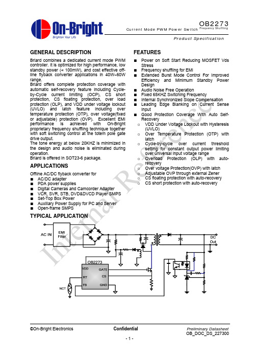
GENERAL DESCRIPTIONBriard combines a dedicated current mode PWM controller. It is optimized for high performance, low standby power (< 100mW), and cost effective off-line flyback converter applications in 40W~60W range.Briard offers complete protection coverage with automatic self-recovery feature including Cycle-by-Cycle current limiting (OCP), CS short protection, CS floating protection, over load protection (OLP), and VDD under voltage lockout (UVLO) and latch feature including over temperature protection (OTP), over voltage(fixed or adjustable) protection (OVP). Excellent EMI performance is achieved with On-Bright proprietary frequency shuffling technique together with soft switching control at the totem pole gate drive output.The tone energy at below 20KHZ is minimized in the design and audio noise is eliminated during operation.Briard is offered in SOT23-6 package.APPLICATIONSOffline AC/DC flyback converter for ■ AC/DC adapter■ PDA power supplies■ Digital Cameras and Camcorder Adapter ■ VCR, SVR, STB, DVD&DVCD Player SMPS ■ Set-Top Box Power■ Auxiliary Power Supply for PC and Server ■ Open-frame SMPSFEATURES■Power on Soft Start Reducing MOSFET Vds Stress■ Frequency shuffling for EMI■ Extended Burst Mode Control For ImprovedEfficiency and Minimum Standby Power Design■ Audio Noise Free Operation■ Fixed 65KHZ Switching Frequency■ Internal Synchronized Slope Compensation ■ Leading Edge Blanking on Current SenseInput■ Good Protection Coverage With Auto Self-Recoveryo VDD Under Voltage Lockout with Hysteresis(UVLO)o Over Temperature Protection (OTP) withlatcho Cycle-by-cycle over current thresholdsetting for constant output power limiting over universal input voltage rangeo Overload Protection (OLP) with auto-recoveryo Over voltage Protection(OVP) with latch o Adjustable OVP through external Zener o CS floating protection with auto-recovery o CS short protection with auto-recoveryTYPICAL APPLICATIONProduct Specificationt al Re fe r en c eGENERAL INFORMATIONPin ConfigurationThe OB2273 is offered in SOT23-6 package,shown as below.Ordering Information Part Number Description OB2273MP SOT23-6, Pb-free in T&RPackage Dissipation Rating Package R θJA(℃/W)SOT23-6 200Absolute Maximum Ratings Parameter Value VDD DC Supply Voltage 40 V VDD Zener ClampVoltage NoteVDD_Clamp+0.1VVDD DC Clamp Current 10 mA FB Input Voltage -0.3 to 7V Sense Input Voltage -0.3 to 7V RT Input Voltage -0.3 to 7V Min/Max OperatingJunction Temperature TJ -20 to 150 oCMin/Max StorageTemperature Tstg-55 to 160 oCNote:VDD_Clamp has a nominal value of 32V.Stresses beyond those listed under “absolute maximum ratings” may cause permanent damage to the device. These are stress ratings only, functional operation of the device at these or any other conditions beyond those indicated under “recommended operating conditions” is not implied. Exposure to absolute maximum-rated conditions for extended periods may affect device reliability.I nt er n a l Re fe r en c eMarking InformationTERMINAL ASSIGNMENTSFor SOT23-6Pin Name I/O Description GND P GroundFB IFeedback input pin. The PWM duty cycle is determined by voltage level into this pinand the current-sense signal at Pin 3.RT I Dual function pin. Either connected through a NTC resistor to ground for overtemperature shutdown/latch control or connected through Zener to VDD foradjustable over voltage protectionCS I Current sense input VDD P PowerSupply Gate O Totem-pole gate driver output for power MosfetRECOMMENDED OPERATING CONDITIONSymbol ParameterMin/Max Unit VDD VDD Supply Voltage10 to 30 V T AOperating Ambient Temperature-20 to 85℃C: Optional Internal CodeI nt er n al Re fe ren c eBLOCK DIAGRAMI nt e r n al R e fe r en c eELECTRICAL CHARACTERISTICS(T A = 25℃, VDD=16V, unless otherwise noted) Symbol Parameter Test Conditions Min Typ Max UnitSupply Voltage (VDD) IstartupVDD Start up CurrentVDD=11V,MeasureLeakage current into VDD5 20 uA I_VDD_Operation Operation CurrentV FB =3V 1.8 2.5 mA UVLO(ON)VDD Under Voltage LockoutEnter6 7 8 VUVLO(OFF)VDD Under Voltage LockoutExit (Recovery)12.5 13.5 14.5VVpull-up Pull-up PMOS active 13 V Vdd_clampIvdd =10mA 30 32 34 V OVP(ON) Over voltage protectionvoltageCS=0V,FB=3VRamp up VDD until gate clock is off24 26 28 VVlatch_release Latch release voltage 5 V Feedback Input Section(FB Pin)V FB_Open V FB Open Loop Voltage 3.9 4.2 VAvcs PWM input gain ΔVFB/ΔVCS2 V/VMaximum duty cycle Max duty cycle @VDD=14V,VFB=3V,VCS=0V75 80 85 %Vref_green The threshold enter greenmode1.4 VVref_burst_H The threshold exit burstmode0.675 VVref_burst_L The threshold enter burstmode0.575 VI FB _Short FB pin short circuit current Short FB pin to GNDand measure current0.3 mAV TH _PL Power Limiting FBThreshold Voltage3.7 VT D _PL Power limiting DebounceTime80 88 96 mSecZ FB _IN Input Impedance 4 Kohm Current Sense Input(Sense Pin) Soft start time 4 ms T_blanking Leading edge blanking time 220 ns Z SENSE _IN Input Impedance 40 KohmT D _OC Over Current Detection andControl DelayFrom Over CurrentOccurs till the Gatedrive output start to turn off120nSec V TH _OC Internal Current Limiting Threshold Voltage FB=3.3V0.75 VVocp_clamper CS voltage clamper 0.9 V OscillatorF OSC Normal Oscillation Frequency VDD =14V, FB =3V,CS=0V60 65 70 KHZ△f_OSC Frequency jittering +/-4 % F_shuffling Shuffling frequency 32 Hz△f_Temp Frequency TemperatureStability1 %I nt er n al Re fe r en c e△f_VDD Frequency Voltage Stability 1 % F_Burst Burst Mode BaseFrequency22 KHZGate driver VOLOuput low level @VDD=14V, Io=5mA1 VVOH Ouput high level @VDD=14V, Io=20mA6 VV_clamp Output clamp voltage 12 VT_r Output rising time 1V ~ 12V@ CL=1000pF175 nST_f Output falling time 12V ~ 1V@ CL=500pF85 nSOver temperature protection IRT Output current of RT pin 95 100 105uA VOTP Threshold voltage for OTP 0.95 1 1.05V Td_OTP OTP debounce time 32 Cycle VRT_FL Float voltage at RT pin 2.3 VVth_OVP External OVP thresholdvoltage4 VI nt er n al Re fe r en c eCHARACTERIZATION PLOTSVDD = 18V, TA = 25℃ condition applies if not otherwise noted.OPERATION DESCRIPTIONThe Briard is a low power off-line SMPS Switcher optimized for off-line flyback converter applications in 40W~60W power range. The ‘Extended burst mode’ control greatly reduces the standby power consumption and helps the design easily to meet the international power conservation requirements.• Startup Current and Start up ControlStartup current of Briard is designed to be very low so that VDD could be charged up above UVLO threshold level and device starts up quickly. A large value startup resistor can therefore be used to minimize the power loss yet achieve a reliable startup in application. For AC/DC adapter with universal input range design, a 2 M Ω, 1/8 W startup resistor could be used together with a VDD capacitor to provide a fast startup and yet low power dissipation design solution.• Operating CurrentThe Operating current of Briard is low at 1.8mA. Good efficiency is achieved with Briard low operating current together with the ‘Extended burst mode’ control features.• Soft StartBriard features an internal 4ms soft start to soften the electrical stress occurring in the power supply during startup. It is activated during the power on sequence. As soon as VDD reaches UVLO(OFF), the CS peak voltage is gradually increased from 0.15V to the maximum level. Every restart up is followed by a soft start.• Frequency shuffling for EMI improvement The frequency Shuffling (switching frequency modulation) is implemented in Briard. The oscillation frequency is modulated so that the tone energy is spread out. The spread spectrum minimizes the conduction band EMI and therefore eases the system design.• Extended Burst Mode OperationAt light load or zero load condition, most of the power dissipation in a switching mode power supply is from switching loss on the MOSFET, the core loss of the transformer and the loss on the snubber circuit. The magnitude of power loss is in proportion to the switching frequency. Lower switching frequency leads to the reduction on the power loss and thus conserves the energy.The switching frequency is internally adjusted at no load or light load condition. The switch frequency reduces at light/no load condition to improve the conversion efficiency. At light load or no load condition, the FB input drops below burst mode threshold level and device enters Burst Mode control. The Gate drive output switches only when VDD voltage drops below a preset level and FB input is active to output an on state. Otherwise the gate drive remains at off state to minimize the switching loss and reduces the standby power consumption to the greatest extend.The switching frequency control also eliminates the audio noise at any loading conditions.• Oscillator OperationThe switching frequency of Briard is internally fixed at 65KHZ. No external frequency setting components are required for PCB design simplification.• Current Sensing and Leading Edge Blanking Cycle-by-Cycle current limiting is offered in Briard current mode PWM control. The switch current is detected by a sense resistor into the sense pin. An internal leading edge blanking circuit chops off the sensed voltage spike at initial internal power MOSFET on state due to snubber diode reverse recovery and surge gate current of power MOSFET so that the external RC filtering on sense input is no longer needed. The current limiting comparator is disabled and cannot turn off the internal power MOSFET during the blanking period. The PWM duty cycle is determined by the current sense input voltage and the FB input voltage.• Internal Synchronized Slope Compensation Built-in slope compensation circuit adds voltage ramp onto the current sense input voltage for PWM generation. This greatly improves the close loop stability at CCM and prevents the sub-harmonic oscillation and thus reduces the output ripple voltage.• DriveThe power MOSFET is driven by a dedicated gate driver for power switch control. Too weak the gate drive strength results in higher conduction and switch loss of MOSFET while too strong gate drive results the compromise of EMI.A good tradeoff is achieved through the built-in totem pole gate design with right output strengthI nt er n al Re fe r en c eand dead time control. The low idle loss and good EMI system design is easier to achieve with this dedicated control scheme. • Protection ControlsGood power supply system reliability is achieved with auto-recovery protection features including Cycle-by-Cycle current limiting (OCP), Over Load Protection (OLP), CS short protection, CS floating protection, and Under Voltage Lockout on VDD (UVLO), and latch features including over temperature protection (OTP), fixed or adjustable over voltage protection (OVP).With On-Bright Proprietary technology, the OCP is line voltage compensated to achieve constantoutput power limit over the universal input voltage range.At overload condition when FB input voltage exceeds power limit threshold value for more than TD_PL, control circuit reacts to shut down the switcher. Switcher restarts when VDD voltage drops below UVLO limit. For latch mode, control circuit shutdowns (latch) the power MOSFET when an Over Temperature condition or Over Voltage condition is detected until VDD drops below 5V (Latch release voltage) , and device enters power on restart-up sequence thereafter .I nt er n al Re fe r en c ePACKAGE MECHANICAL DATADimensions In Millimeters Dimensions In Inches SymbolMin Max Min MaxA 1.000 1.300 0.039 0.051 A1 0.000 0.150 0.000 0.006 A2 1.000 1.200 0.039 0.047 b 0.300 0.500 0.012 0.020 c 0.100 0.200 0.004 0.008 D 2.800 3.020 0.110 0.119 E 1.500 1.700 0.059 0.067 E1 2.600 3.000 0.102 0.118 e 0.950 (BSC) 0.037 (BSC)e1 1.800 2.000 0.071 0.079 L 0.300 0.600 0.012 0.024 θ 0º 8º 0º 8ºI nt er n al Re fe r en c e©On-Bright Electronics Confidential Preliminary DatasheetOB_DOC_DS_227300- 11 - OB2273 Current Mode PWM Power Switch Frequency ShufflingIMPORTANT NOTICERIGHT TO MAKE CHANGESOn-Bright Electronics Corp. reserves the right to make corrections, modifications, enhancements, improvements and other changes to its products and services at any time and to discontinue any product or service without notice. Customers should obtain the latest relevant information before placing orders and should verify that such information is current and complete.WARRANTY INFORMATIONOn-Bright Electronics Corp. warrants performance of its hardware products to the specifications applicable at the time of sale in accordance with its standard warranty. Testing and other quality control techniques are used to the extent it deems necessary to support this warranty. Except where mandated by government requirements, testing of all parameters of each product is not necessarily performed.On-Bright Electronics Corp. assumes no liability for application assistance or customer product design. Customers are responsible for their products and applications using On-Bright’s components, data sheet and application notes. To minimize the risks associated with customer products and applications, customers should provide adequate design and operating safeguards.LIFE SUPPORTOn-Bright Electronics Corp.’s products are not designed to be used as components in devices intended to support or sustain human life. On-bright Electronics Corp. will not be held liable for any damages or claims resulting from the use of its products in medical applications.MILITARYOn-Bright Electronics Corp.’s products are not designed for use in military applications. On-Bright Electronics Corp. will not be held liable for any damages or claims resulting from the use of its products in military applications.I nt e r n a l R e f e r e n c e。
基于OB2273的单端反激式开关电源设计

基于OB2273的单端反激式开关电源设计韩召成;文定都;胡正国;任于涵【摘要】设计了一种基于OB2273的单端反激式开关电源.先介绍了开关电源的设计原理,再分析部分模块的功能及工作原理.为了满足电源的电磁兼容性和输出电压的稳定性等要求,利用EMI滤波器滤除干扰,采用稳压源TL431和光耦实现了反馈.实验测试结果表明,该开关电源具有输出直流电压稳定、转换效率高、纹波小、体积小等优点,满足设计要求.【期刊名称】《湖南工业大学学报》【年(卷),期】2017(031)004【总页数】5页(P39-43)【关键词】OB2273;反激式;开关电源【作者】韩召成;文定都;胡正国;任于涵【作者单位】湖南工业大学电气与信息工程学院,湖南株洲 412007;湖南工业大学电气与信息工程学院,湖南株洲 412007;湖南工业大学电气与信息工程学院,湖南株洲 412007;湖南工业大学电气与信息工程学院,湖南株洲 412007【正文语种】中文【中图分类】TN86随着电力电子技术的快速发展,开关电源朝着集成化、小型化、高频化的方向发展,并在日常生活中得到了广泛运用。
开关电源和线性电源相比,具有以下特点:效率高,体积小,可靠性高,稳压范围广,性能好,驱动能力强[1-3]。
开关电源的控制方式有电压控制方式和电流控制方式2种。
电流型PWM(pulse width modulation)开关电源和电压型PWM开关电源相比,具有输出稳定性好、电压和负载调整率高等特点[4-8]。
文献[4]提出了电流型PWM整流器直流侧滤波器,通过选取适当的滤波器参数,减少了电抗压降带来的损耗,提高了系统效率。
文献[5]提出了电流型整流器双闭环多变量反馈控制策略,该策略优化了系统性能,提高了系统的抗干扰性与稳定性。
文献[6]提出了基于空间矢量的三相CSR(current source recti fi er)低电压应力控制方法,使三相CSR电流具有电流利用率高、开关损耗小、动态响应快等优点。
OB2273 Demo Board Manual
2
3 Performance Evaluation..................................................................................................................... 10 3.1 Input Characteristics ................................................................................................................11 3.1. 1 Input current and Standby power ............................................................................................11 3.1. 2 Efficiency .................................................................................................................................11 3.2 Output Characteristics .............................................................................................................11 3.2.1 Line Regulation & Load Regulation..........................................................................................11 3.2.2 Ripple & Noise......................................................................................................................... 12 3.2.3 Overshoot & Undershoot ....................................................................................................... 13 3.2.4 Dynamic Test ......................................................................................................................... 14 3.2.5 Time Sequence...................................................................................................................... 14 3.3 Protections .............................................................................................................................. 15 3.3.1 Over Current Protection (OCP) ............................................................................................. 15 3.3.2 Over Voltage Protection (OVP).............................................................................................. 15 3.3.3 Over Load Protection (OLP) .................................................................................................. 16 3.3.4 Over Temperature Protection (OTP)...................................................................................... 16 3.4 EMI Test.................................................................................................................................. 17 3.4.1 Conduction EMI Test ............................................................................................................. 17 3.4.2 Radiation EMI Test ................................................................................................................ 18 4 Other important waveform ................................................................................................................. 19 4.1 CS, FB, Vdd & Vds waveform at no load/full load. ................................................................. 19 4.2 Vds waveform at full load, start/normal/output short............................................................... 19 4.2.1 VDS at full load, start/normal/output short .............................................................................. 19 4.2.2 Vds at full load, start waveform ............................................................................................... 20 4.2.3 Vds at full load, normal waveform ........................................................................................... 20 4.2.4 Vds at full load, output short waveform ................................................................................... 20
电化学工作站2273说明书

PARSTAT 2273Advanced Potentiostat/Galvanostat/FRA®Princeton Applied ResearchWe would like to introduce the new benchmark!The PARSTAT 2273 is the combination of the renowned reliability, high current, and high compliance voltage of the 273A with the exceptional impedance capability, resolution, speed and latest software techniques of our new PARSTAT family. Plus we’ve incorporated customer feedback to provide not only more internal maximum current but the ability to boost the 20 A and the ability to interface all the ancillary equipment customers need today for their unique research.The 2273 is designed to be the most comprehensive potentiostat/galvanostat/FRA in your laboratory. Since no one can predict how research needs will evolve over the years, we’ve designed the ultimate electrochemical tool to satisfy your needs not only for today — but for tomorrow.Major Features• 2 A current max. (20 A boosted)• 100 V compliance• 1.2 fA current resolution • >1013Ωinput impedance • <5 pF of capacitance• 10 µHz to 1 MHz built in analyzer for impedanceFor more than two decades, the 273/273A has been the most popular instrument in the history ofcomputer-controlled potentiostats/galvanostats. We knew how critical it would be that the next generation of this prestigious instrument continue to set the standard against which all other systems will be measured.Applications• Research Electrochemistry • Corrosion • Sensors• Batteries/Fuel Cells• Electrodeposition/Plating • Biomedical ApplicationsGeneral SpecificationsThe 2273 is an advanced potentiostat/galvanostat/FRAthat consists of hardware capable of ±10 V scan ranges, 2 A current capability, and EIS measurements from 10 µHz to 1 MHz. The interface to the PC or laptop is Universal Serial Bus (USB), so there is no need for an additional card for your system. Electrochemistry PowerSuite software is required for the 2273.Current and VoltageUnlike any other potentiostat on the market today, the 2273 offers a unique combination of compliance voltage up to±100 V (power available at the counter electrode) and a maximum current of up to ±2 A.EIS CapabilityThe 2273 hardware combined with PowerSINE software can perform EIS experiments from 1 MHz to 10 µHz. These measurements can control either potentiostatic (Single Sine, Fast MultiSine, or Mott-Schottky), or galvanostatic (Galvanostatic EIS) experiments.Booster InterfaceThe 2273 has three current booster options to choose from:• 8A/2273 option for 8 A, 50 V• 10A/2273 option for 10 A, 20 V• 20A/2273 option for 20 A, 20 VUsing the 2273 with one of the current booster options provides the user witha seamless interface for our PowerSuite software. When a booster option isconnected to the 2273, the software will autoscale the data.2PARSTAT 2273Advanced Potentiostat/Galvanostat/FRA®3EIS Contour Plot for the 2273Princeton Applied Research has performed a series of impedance experiments on known resistive and capacitive cells and has evaluated the accuracy of these measurements. The typical results are summarized on the contour plot.The experiments were made in the potentiostatic EIS mode, using a standard amplitude of 10 mV. The blue area is the region for which the error in theimpedance is less than 1% or 2°.4ApplicationsResearch ElectrochemistryThe physical nature of electrochemistry has resulted in a broad range of research areas. Fromdetermining the kinetics of an electron-transfer process, to developing new and improved materials via unique electrodeposition or electrosynthesis techniques, the 2273 was designed with the flexibility and capability required by today's electrochemical researcher. Whether it is amicroelectrode, rotating disk electrode, mercury electrode, or quartz crystal resonator being measured, the 2273 supports the wide array of electrodes used in a modern electrochemical research lab.CorrosionThe 2273 is ideal for corrosion research. For measurements of rebar in concrete or titanium in Ringer's solution, the 2273 was designed to address a wide range of corrosion applications.PowerCORR Corrosion Software and PowerSINE EIS Software complement the 2273'simpressive specifications to create the ultimate tool for any corrosion lab. Are you working with large electrodes or resistive media? The 2273's 100 V compliance voltage takes care of that.Studying a new corrosion inhibitor or coating technology? Femtoamp current resolutions and >1013input impedance make even the toughest EIS measurements seem routine.SensorsFor potentiometric sensors (such as ion-selective electrodes and coated wire electrodes) and amperometric sensors (gas sensors, thin film microelectrodes, and chemically modifiedelectrodes), the 2273 provides current sensitivities that can surpass the requirements of the most demanding measurement parameters, with a pA current range and fA resolution; high compliance voltage allows for the growth of thin film electrodes and nanodeposition. Biosensordevelopment and analysis relies on techniques that are contained within the PowerCV cyclic voltammetry, PowerSTEP chronoamperometry/chronopotentiometry and PowerPULSE electroanalytical software packages.Fuel Cells and BatteriesFor many years, Princeton Applied Research potentiostats/galvanostats have been utilized to further the development of new energy sources. From the early stages of battery development to the charge/discharge experiments on the final product, the 2273 has the current measurement range to address the challenges that lie ahead for the next generation ofbatteries. Fuel Cells offer a cleaner energy source for the future, and the 2273 helps bring that technology to market. Use EIS to examine the impedance of the PEM at different humiditylevels, perform I/V curves on SOFCs, or run CVs on DMFC assemblies. The 2273 and the entire PowerSuite package has the potential to take your research to the next level.Biomedical ApplicationsThe 2273 exceeds the requirements of a potentiostat/galvanostat as described in ASTM F2129, “Standard Test Method for Conducting Cyclic Potentiodynamic Polarization Measurements to Determine the Corrosion Susceptibility of Small Implant Devices.” For implant biocompatibility studies, the most common methods involve DC corrosion techniques such as cyclic potentiodynamic polarization for the determination of the breakdown or critical pitting potential (Eb), the corrosion or open circuit potential (Ecorr), the repassivation or protection potential (Ep), corrosion current (Icorr) and corrosion rates based on Tafel analysis. All of these techniques are possible with the 2273 using the PowerCORRcorrosion measurement software package. The outstanding performance of the 2273 ensures that the results obtained are accurate and allows the user to be confident of their data.PARSTAT 2273Advanced Potentiostat/Galvanostat/FRA®5Ordering InformationModelDescription2273Advanced Potentiostat/Galvanostat/FRA 8A/22738 A @ 50 V Booster Option 10A/227310 A @ 20 V Booster Option 20A/227320 A @ 20 V Booster OptionPowerSuite Software ModulesPowerSINE ®Electrochemical Impedance Spectroscopy PowerCORR™Corrosion Measurement PowerCV ®Cyclic VoltammetryPowerSTEP ®Chronoamperomtry/Chronopotentiometry PowerPULSE™Electroanalytical TechniquesCable AccessoriesC0379Additional 2273 Cell CableC03802273 to Glove Box Interface Cable (call for information and quotation)Cell AccessoriesK0047Corrosion Cell Kit K0235Corrosion Flat Cell K0264Micro-Cell Kit RDE0018Analytical Cell KitAncillary Equipment303A Static Mercury Drop Electrode 507Interface for the Model 303A QCM922Quartz Crystal Microbalance 616Rotating Disk Electrode636Rotating Ring-Disk ElectrodeExtended Warranty2273-EWSilver Extended Warranty Plan for the 2273Princeton Applied Research offers extended warranties and/or site service contracts on all its instruments. There are three levels of coverage starting with the basic silver level that is a one-year extension of our free one-year initialwarranty. Silver level extended warranty includes labor, material, and return shipping. The Gold and Platinum levels offer an increased product protection plan, including priority repair and free loaner instruments if available.ISO9001:2000 CertifiedPrinceton Applied Research is a member of Advanced Measurement Technology, Inc., an ISO9001:2000 certified company.SoftwareDiscover the power of true 32-bit Windows programs in the Princeton Applied Research PowerSuite software platform.Take advantage of powerful wizards, graphical data presentation formats and easy-to-use import/export tools for both graphs and data.PowerPULSE™• Recurrent Potential Pulsing • Recurrent Galvanic Pulsing • Square Wave Voltammetry• Cyclic Square Wave Voltammetry • Differential Pulse Voltammetry• Cyclic Differential Pulse Voltammetry • Normal Pulse Voltammetry• Reverse Normal Pulse Voltammetry • R ΩDeterminationPowerCV ®• Linear Scan• Ramp Cyclic VoltammertyOne Vertex Two VertexOne Vertex/Multi Cycle Two Vertex/Multi Cycle• Stair Case Cyclic VoltammetryOne Vertex Two VertexOne Vertex/Multi Cycle Two Vertex/Multi CyclePowerSTEP ®• One Step Chronoamperometry • Two Step Chronoamperometry • ChronopotentiometryPowerSINE ®• Potentiostatic EIS • Multi-Sine EIS • Galvanostatic EIS• Potentiostatic Impedance versus Time • Galvanostatic Impedance versus Time • Mott-ShottkyPowerCORR™• Tafel Plot• Anodic Polarization • Linear Polarization • Potentiostatic • Galvanostatic• Ecorr versus Time • Galvanic Corrosion • Cyclic Polarization• Cyclic Polarization (no reverse)• Zero Resistance Ammeter • Galvanodynamic• Galvanodynamic (no reverse)6Recurrent Galvanic Pulsing (PowerPULSE)Impedance vs. Time (PowerSINE)Differential Pulse (PowerPULSE)Two Step Chronoamperometry (PowerSTEP)Peak Analysis Tools (PowerCV)Anodic Polarization (PowerCORR)7Advanced Potentiostat/Galvanostat/FRAData Storage FormatPowerSuite’s unique data storage format ulitizing Microsoft ®ACCESS database provides other powerful features available to PowerSuite. These include making changes to someexperimental parameters on the fly, performing fits on data as it is being collected, searching data files based on comments added by the user, and exporting data and plots to otherprograms such as Microsoft Excel and PowerPoint.Complete Plotting ControlOverlay data can be placed on the plots prior to acquiring the data, which allows the user to compare the two data sets as the experiment progresses!Overlaid data graphical properties can also be modified in terms of color or plot style, and any overlaid data can be selected to become the "active" data file, at which point the current file becomes an overlay, and full data analysis can be performed on what was an overlay! A number of graphical and analyticalfeatures are available by simply right-clicking on any graph and selecting from a full complement of options.Experiment WizardFor new users, the "New Experiment Wizard" guides you through a step-by-step process to configure all aspects of the experiment. If you have a setup that is to be repeated over several experiments, it can be "Saved as a Template...", recalled, and executed without having to re-enter information with each use.Powerful GraphicsPowerSuite’s dominant features are it’s graphical capabilities. Tremendous flexibility is provided with data presentation.Up to four plots can be viewed simultaneously, on the screen without opening a separate viewing program. Severaldefault plots are available, and the user has the ability to modify each graph or create and save their own custom graphs according to specified criteria. Awide variety of parameters are available for plotting, as well as the ability to add a second Y-axis or view the plot in 3D. The user can select the data symbols/lines desired, as well as change the color of any plot. Additional graphical features allow the data of any axis to be mathematically changed (by choosing to either add, subtract, divide, or multiply the axis values) using the Data Factors feature.This feature can be used to change data in amps to microamps for comparison purposes. It can also be used to convert a potential reading acquired from an ancillary component (such as a temperature probe) through the A/D Input into its proper value (such as degrees C).Specifications subject to change042804 info@ 801 South Illinois Avenue, Oak Ridge, TN 37831-0895 U.S.A.(800) 366-2741 or (865) 482-4411 • Fax (865) 425-1334For International Office Locations, Visit Our WebsiteADVANCED MEASUREMENT TECHNOLOGYPrinceton Applied Research Advanced Potentiostat/Galvanostat/FRASpecificationsPower AmplifierCompliance Voltage: ±100 VMaximum Current: ±2 ARise Time: <250 ns (No Load)Slew Rate: >15 V/µs (No Load)System PerformanceMinimum Time Base: 20 µsMinimum Potential Step: 2.5 µVNoise and Ripple: <50 µV/rms (typical)Minimum Current Range: 2 nA(hardware)Minimum Current Range: 40 pA(after 50X gain) Minimum Current Resolution: 1.2 fAiR CompensationPositive Feedback Range: 2000 MΩto 2 Ω(depending on current range)Current Interrupt: 16 bit DAC Potential Error Correction Current MeasurementRanges: 12 decades, 2 A to 40 pA(with internal gain applied)Accuracy (dc)20 µA to 2A: <0.4% Full Scale20 nA and 1 µA Ranges: <0.5%2 nA< 0.75%Frequency Response (small signal)2 mA Range:3 dB at >1 MHz, 1k source impedance20 µA Range: 3 dB at >100 kHz, 100k source impedance Differential ElectrometerInput Bias Current: <5 pA at 25°CMax. Voltage Range: ±10 VMax. Input Voltage Differential: ±10 VBandwidth: 3 dB @ >15 MHzCommon Mode Rejection:>80 dB at 100 Hz>60 dB at 100 kHzInput Impedance: >1013Ωin parallel with <5 pF Potential/Current ControlDigital/Analog Converters (DACs)Bias DACResolution: 16 bitsRange (Potentiostat): ±10 VRange (Galvanostat): ±100% of full-scale current Modulation DACResolution: 16 bitsImpedance SpecificationsFrequency Range: 10 µHz–1 MHz Dimensions58 cm W x 47.6 cm D x 22.9 cm H(20" W x 18.75" D x 9" H)Weight31 kg (68 lbs)Power Requirements90/130 V AC or 200/260 V AC, 50-60 Hz600 Watts MaximumComputer InterfaceUniversal Serial BusPowerSuite Software (sold separately) PowerSINE Electrochemical Impedance Spectroscopy PowerCORR Corrosion MeasurementPowerCV Cyclic VoltammetryPowerSTEP Chronoamperometry/Chronopotentiometry PowerPULSE Electroanalytical SoftwareFor discounts available on bundled packages, please contact your local sales representative.Operating SystemMicrosoft Windows‚ 95/98/2000/NT/XP。
芯联半导体---LED驱动IC上典型应用方案

PFC Controller
Mobile and cordless phone charger
CL1158 CL1100 CL1128 CL1101 1W 7W 10W 20W 30W 300W CL6562
Chiplink LED Lighting Solution
LED driver solution
AC-DC PSR IC Competitive Cross Reference Guide(Low -end) Guide(Low-end)
Working Mode
CL1128 PFM+PWM
AP3765 PFM BJT
BF1501/150 FT831 2 PFM+PWM BJT PFM BJT
芯联半导体有限公司 We deliver world-class innovations… for customer-focused impact
公司概况 Company Profile
�
�
Chiplink-Semi Inc.
Founded in 2007, Chiplink, develops and manufactures power supply control ICs. The company consistently delivers inventive power management solutions that improve the performance of consumer electronics, computers, and LED lighting. Chiplink adds value to end equipment by synthesizing technological innovation, uncompromised quality, and devotion to customer service. Chiplink design teams hail from distinguished analog semiconductor companies and top universities with extensive experience per designer. The teams have brought many innovative product suites to market and helped increase the company ’ s annual revenue by an average of 100% between 2007 and 2011. Chiplink is committed to grow into a world class analog IC company by offering diversified high performance IC products in state of art CMOS, BiCMOS and BCD technologies to LDO, DC/DC and AC/DC.
Omega 22 mm OMPBD7 推按钮和选择开关系列产品说明书
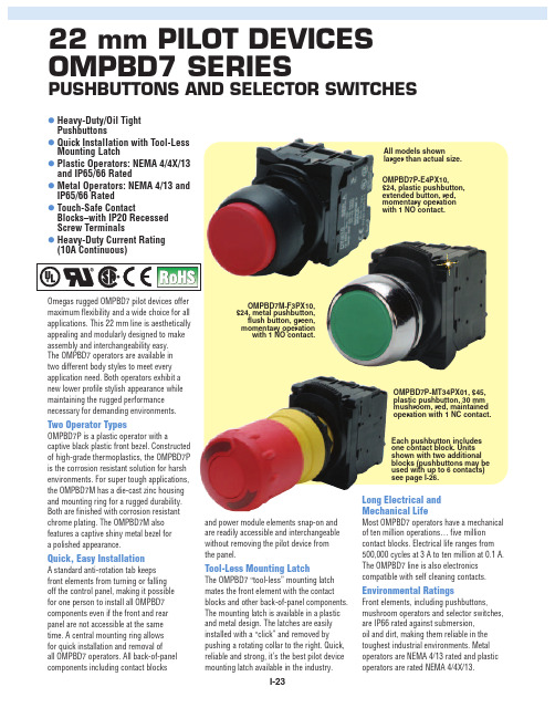
22 mm PILOT DEVICES OMPBD7 SERIESPUSHBUTTONS AND SELECTOR SWITCHESOmegas rugged OMPBD7 pilot devices offer maximum flexibility and a wide choice for all applications. This 22 mm line is aesthetically appealing and modularly designed to make assembly and interchangeability easy. The OMPBD7 operators are available in two different body styles to meet every application need. Both operators exhibit a new lower profile stylish appearance while maintaining the rugged performance necessary for demanding environments.Two Operator TypesOMPBD7P is a plastic operator with acaptive black plastic front bezel. Constructed of high-grade thermoplastics, the OMPBD7P is the corrosion resistant solution for harsh environments. For super tough applications,the OMPBD7M has a die-cast zinc housing and mounting ring for a rugged durability.Both are finished with corrosion resistant chrome plating. The OMPBD7M also features a captive shiny metal bezel for a polished appearance.Quick, Easy InstallationA standard anti-rotation tab keeps front elements from turning or falling off the control panel, making it possible for one person to install all OMPBD7components even if the front and rear panel are not accessible at the same time. A central mounting ring allows for quick installation and removal of all OMPBD7 operators. All back-of-panel components including contact blocksand power module elements snap-on and are readily accessible and interchangeable without removing the pilot device from the panel.Tool-Less Mounting LatchThe OMPBD7 “tool-less” mounting latch mates the front element with the contact blocks and other back-of-panel components.The mounting latch is available in a plastic and metal design. The latches are easily installed with a “click” and removed by pushing a rotating collar to the right. Quick,reliable and strong, it’s the best pilot device mounting latch available in the industry.Long Electrical and Mechanical LifeMost OMPBD7 operators have a mechanical of ten million operations… five million contact blocks. Electrical life ranges from 500,000 cycles at 3 A to ten million at 0.1 A.The OMPBD7 line is also electronics compatible with self cleaning contacts.Environmental RatingsFront elements, including pushbuttons,mushroom operators and selector switches,are IP66 rated against submersion, oil and dirt, making them reliable in the toughest industrial environments. Metal operators are NEMA 4/13 rated and plastic operators are rated NEMA 4/4X/13.OMPBD7M-F3PX10, $24, metal pushbutton,flush button, green,momentary operation with 1 NO contact.OMPBD7P-E4PX10, $24, plastic pushbutton,extended button, red,momentary operation with 1 NO contact.OMPBD7P-MT34PX01, $45,plastic pushbutton, 30 mm mushroom, red, maintained operation with 1 NC contact.Each pushbutton includes one contact block. Units shown with two additionalblocks (pushbuttons may be used with up to 6 contacts)see page I-26.l Heavy-Duty/Oil Tight Pushbuttonsl Quick Installation with Tool-Less Mounting Latchl Plastic Operators: NEMA 4/4X/13and IP65/66 Ratedl Metal Operators: NEMA 4/13 and IP65/66 Ratedl Touch-Safe ContactBlocks–with IP20 Recessed Screw Terminalsl Heavy-Duty Current Rating(10A Continuous)All models shownlarger than actual size.Additional Featuresand OptionsHeavy-Duty Ratings—The OMPBD7 lineis UL 46E, NEMA A600 and Q600 listed. All components carry a 10 Amp continuous current rating, covering all industrial control needs.All Major Approvals—OMPBD7 front elements are UL Recognized, while all OMPBD7 assemblies are UL Approved. The line is also approved by every major international agency making themideal for export requirements.H-Bridge & Gold Plated Contacts—By doubling the available paths for current to pass through the contacts, the standard H-bridge design provides a cleaner current flow. Gold plated contacts quadruple the current paths for increased contact reliability in low voltage applications.Touch-Safe—Back of panel components are finger safe, with IP20 protection.Long Lasting Integral LED Assemblies—Our new LED lamps last up to 11 years! They are conveniently offered as a complete unit for all illuminated operators which include the one piece Integral LED Module. They come in five different colors: amber, blue, green, red and white.OMPBD7M-HM22PX01, two way metal selector switch with long knob.Each unit includes tool-less mounting latch and one normally closed contact block.Shown with two additional (up to 6 total per operator possible) normally opencontact blocks, model OMPBD7-X10, $8.50 each.All shown largerthan actual size.CONTACT BLOCKSRed = normally closed.OMPBD7-X01, $8.50.OMPBD7-X10, $8.50.Green = normally open.Rear view.OMPBD7P-LMM43PX10, $39, plastic pushbutton,green, 40 mm mushroom,momentary operation, one NO contact, shown larger than actual size.OMPBD7P-LE4PX01, $30, plastic pushbutton, extended button, red, momentary operation, one NC contact,shown larger than actual size.22 mm PUSHBUTTONSILLUMINATED PUSHBUTTONS AND E-STOPSOMPBD7-IL Series Start at$51(Specify Model Number)MOST POPULAR MODELS HIGHLIGHTED!used per operator (light module occupies center position).*Insert number for color selection, 2= black, 3= green, 4= red, 5= yellow, 6= blue.Complete with pushbutton and light moduleEach operator includestool-less mounting latch and one contact block. Shown with two additional (up to 4total per operator possible)contact blocks.used per operator.Front-of-Panel (Operators)1Notes:1Performance data given in this publication is provided only as a guide for the user in determining suitability and do not constitute a performance warranty of any kind. Such data may represent the results of accelerated testing at elevated stress levels, and the user is responsible for correlating the data to actual application requirements. ALL WARRANTIES AS TO ACTUAL PERFORMANCE, WHETHER EXPRESS OR IMPLIED, ARE EXPRESSLY DISCLAIMED.2Momentary mushroom operators are IP65, multi-function operators are not Type 13 rated. Plastic operators with keys are not Type 4X rated.3Operating temperatures below 0°C (32°F) are based on the absence of freezing moisture and liquids, UL recognized to 55°C (131°F)incandescent module, max 40°C (104°F).22 mm PILOT DEVICESHEAVY-DUTY/OIL TIGHT PUSHBUTTONSAND SELECTOR SWITCHES OMPBD7 SERIESNon-illuminated pushbuttons, shown on pages I-25 and I-26.Notes:1Performance data given in this publication is provided only as a guide for the user in determining suitability and do not constitute a performance warranty of any kind. Such data may represent the results of accelerated testing at elevated stress levels, and the user is responsible for correlating the data to actual application requirements. ALL WARRANTIES AS TO ACTUAL PERFORMANCE, WHETHER EXPRESS OR IMPLIED, ARE EXPRESSLY DISCLAIMED.4Low voltage contacts are recommended for applications below 17 V, 5 mA.5Wires less than #18 (0.75 mm2) may not hold in terminal securely.CANADA www.omega.ca Laval(Quebec) 1-800-TC-OMEGA UNITED KINGDOM www. Manchester, England0800-488-488GERMANY www.omega.deDeckenpfronn, Germany************FRANCE www.omega.fr Guyancourt, France088-466-342BENELUX www.omega.nl Amstelveen, NL 0800-099-33-44UNITED STATES 1-800-TC-OMEGA Stamford, CT.CZECH REPUBLIC www.omegaeng.cz Karviná, Czech Republic596-311-899TemperatureCalibrators, Connectors, General Test and MeasurementInstruments, Glass Bulb Thermometers, Handheld Instruments for Temperature Measurement, Ice Point References,Indicating Labels, Crayons, Cements and Lacquers, Infrared Temperature Measurement Instruments, Recorders Relative Humidity Measurement Instruments, RTD Probes, Elements and Assemblies, Temperature & Process Meters, Timers and Counters, Temperature and Process Controllers and Power Switching Devices, Thermistor Elements, Probes andAssemblies,Thermocouples Thermowells and Head and Well Assemblies, Transmitters, WirePressure, Strain and ForceDisplacement Transducers, Dynamic Measurement Force Sensors, Instrumentation for Pressure and Strain Measurements, Load Cells, Pressure Gauges, PressureReference Section, Pressure Switches, Pressure Transducers, Proximity Transducers, Regulators,Strain Gages, Torque Transducers, ValvespH and ConductivityConductivity Instrumentation, Dissolved OxygenInstrumentation, Environmental Instrumentation, pH Electrodes and Instruments, Water and Soil Analysis InstrumentationHeatersBand Heaters, Cartridge Heaters, Circulation Heaters, Comfort Heaters, Controllers, Meters and SwitchingDevices, Flexible Heaters, General Test and Measurement Instruments, Heater Hook-up Wire, Heating Cable Systems, Immersion Heaters, Process Air and Duct, Heaters, Radiant Heaters, Strip Heaters, Tubular HeatersFlow and LevelAir Velocity Indicators, Doppler Flowmeters, LevelMeasurement, Magnetic Flowmeters, Mass Flowmeters,Pitot Tubes, Pumps, Rotameters, Turbine and Paddle Wheel Flowmeters, Ultrasonic Flowmeters, Valves, Variable Area Flowmeters, Vortex Shedding FlowmetersData AcquisitionAuto-Dialers and Alarm Monitoring Systems, Communication Products and Converters, Data Acquisition and Analysis Software, Data LoggersPlug-in Cards, Signal Conditioners, USB, RS232, RS485 and Parallel Port Data Acquisition Systems, Wireless Transmitters and Receivers。
OB2273 guide

2.引脚说明:OB2273 封装形式SOT23-6管脚名称管脚编号VDD RT FB GATE GND CSNCTOB2273OB2273 系统工作模式示意图OB2273 采用在重载条件下采用固定频率工作模式。
随着负载降低,进入降频工作模式,提高轻载效率;在负载较轻或空载时,系统进入间歇工作模式,从而降低功耗。
各模式的切换通过系统反馈电压FB来控制,如上图所示:Current-Mode PWM OB2273RT 仅作为RT仅作为OVP Latch protection RT作为OTP and OVP Latch protectionoptionalCurrent-Mode PWM OB2273Current-Mode PWM OB2273 (1)(2) (3)快速启动电路⑤①②③⑥⑦④案例一(40W):100mW设计关键点Current-Mode PWM OB2273系统高低压补偿设计电路Current-Mode PWM OB2273普通反馈补偿电路增加极点反馈补偿电路Current-Mode PWM OB227320V264Vac:SCP,saturation voltage (Vds_sat) is high. Cs pin RC设计Add RC circuit to reduce drain saturation voltage across MOS.CS pin R*太大造成Vds冲高现象从上图FB(红色)波形,可以看到环路加快,从而避免了Vds冲高现象Current-Mode PWM OB2273Current-Mode PWM OB2273说明:1)100mW以下方案设计,效率>87%.Current-Mode PWM OB2273Thank you !。
OB2279规格书
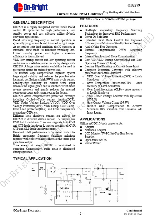
GENERAL DESCRIPTIONOB2279 is a highly integrated current mode PWM control IC optimized for high performance, low standby power and cost effective offline flyback converter applications. PWM switching frequency at normal operation is externally programmable and trimmed to tight range. At no load or light load condition, the IC operates in extended ‘burst mode’ to minimize switching loss. Lower standby power and higher conversion efficiency is thus achieved. VDD low startup current and low operating current contribute to a reliable power on startup design with OB2279. A large value resistor could thus be used in the startup circuit for reduced power loss. The internal slope compensation improves system large signal stability and reduces the possible sub-harmonic oscillation at high PWM duty cycle output. Leading-edge blanking on current sense input removes the signal glitch due to snubber circuit diode reverse recovery and greatly reduces the externalcomponent count and system cost in the design.OB2279 offers comprehensive protection coverageincluding Cycle-by-Cycle current limiting(OCP),VDD Under Voltage Lockout(UVLO), VDD OverVoltage Protection(OVP), VDD Clamp, Gate Clamp,Over Load protection(OLP) and Over Temperatureprotection (OTP), etc.Different latch shutdown options are offered onOB2279 in different device version. V version has OVP Latch shutdown. T version supports both OVP and OTP latch shutdown. L version provides all OVP, OTP and OLP latch shutdown control. Excellent EMI performance is achieved with On-Bright proprietary frequency shuffling technique together with soft switching control at the totem pole gate drive output. Tone energy at below 20KHZ is minimized in operation. Consequently, audio noise is eliminated during operation.OB2279 is offered in SOP-8 and DIP-8 packages.FEATURES■ On-Bright Proprietary Frequency Shuffling Technology for Improved EMI Performance ■ Power On Soft Start■ Extended Burst Mode Control For Improved Efficiency and Minimum Standby Power Design ■ Audio Noise Free Operation■ External Programmable PWM Switching Frequency ■ Internal Synchronized Slope Compensation■ Low VIN/VDD Startup Current(3uA) and Low Operating Current (2.3mA)■ Leading Edge Blanking on Current Sense Input ■ Complete Protection Coverage with selective protections for Latch Shutdown o VDD Over Voltage Protection(OVP) – LatchShutdown o Over Temperature Protection(OTP) – Auto recovery or Latch Shutdowno Over Load Protection. (OLP) – Auto recovery or Latch Shutdown o VDD Under Voltage Lockout with Hysteresis (UVLO) o Gate Output Voltage Clamp (16.5V) o Built-in OCP Compensation to Achieve Minimum OPP Variation over Universal AC Input Range. APPLICATIONSOffline AC/DC flyback converter for ■ Adaptor ■ Notebook Adaptor ■ LCD Monitor/TV/PC/Set-Top Box PowerSupplies■ Open-frame SMPS ■ Printer Power TYPICAL APPLICATIONO n -B ri gh tCo nf id en ti alt oBo na F i d e (贝纳化电)GENERAL INFORMATIONPin ConfigurationThe pin map of OB2279 in DIP8 and SOP8 package is shown as below.Ordering Information Part Number Description OB2279AP-V DIP8, V version with OVPLatchOB2279AP-T DIP8, T version withOVP/OTP latchOB2279AP-L DIP8, L version withOVP/OTP/OLP latchOB2279CP-V SOP8, V version with OVPlatchOB2279CP-T SOP8, T version withOVP/OTP latchOB2279CP-LSOP8, L version with OVP/OTP/OLP latchNote: All Devices are offered in Pb-free Package if not otherwisenoted.Package Dissipation Rating PackageR θJA (°C/W)DIP8 90 SOP8 150Absolute Maximum RatingsParameter Value VDD Clamp Voltage 35 V VDD Clamp Continuous Current10 mA V FB Input Voltage -0.3 to 7V V SENSE Input Voltage to Sense Pin-0.3 to 7V V RT Input Voltage to RT Pin -0.3 to 7V V RI Input Voltage to RI Pin -0.3 to 7V Min/Max Operating Junction Temperature T J-20 to 150 o C Min/Max Storage Temperature T stg-55 to 150 o C Lead Temperature (Soldering, 10secs)260 o C Note: Stresses beyond those listed under “absolute maximumratings” may cause permanent damage to the device. These are stress ratings only, functional operation of the device at these or any other conditions beyond those indicated under “recommended operating conditions” is not implied. Exposure to absolute maximum-rated conditions for extended periods may affect device reliability.O n -B ri gh tCo nf id en ti alt oBo na F i d e (贝纳化电)Marking InformationTERMINAL ASSIGNMENTSPin Num Pin Name I/O Description 1 GND P Ground 2 FB I Feedback input pin. PWM duty cycle is determined by voltage level into thispin and current-sense signal level at Pin 6.3 VIN I Connected through a large value resistor to rectified line input for Startupand line voltage sensing.4 RI I Internal Oscillator frequency setting pin. A resistor connected between RIand GND sets the PWM frequency.5 RT I Dual function pin. Either connected through a NTC resistor to GND for overtemperature shutdown control or used as latch shutdown control input.6 SENSE I Current sense input pin. Connected to MOSFET current sensing resistornode.7 VDD P DC power supply pin. 8 GATE O Totem-pole gate drive output for power MOSFET.O n -B ri gh tCo nf id en ti alt oBo naF i d e (贝纳化电)BLOCK DIAGRAMRECOMMENDED OPERATING CONDITIONSymbol Parameter Min MaxUnitVDD VDD Supply Voltage 11.5 25 V RI RI Resistor Value 100 133 Kohm T A Operating Ambient Temperature-20 85o CO n -B r i gh t Co nf id en ti alt oBo na F i d e (贝纳化电)ELECTRICAL CHARACTERISTICS(T A = 25O C if not otherwise noted)Symbol Parameter Test Conditions Min Typ Max Unit Supply Voltage (VDD) I_VDD_Startup VDD Start up Current VDD =15V, RI=100K Measure current into VDD3 20 uAI_VDD_Ops Operation Current VDD =16V, RI=100Kohm, V FB =3V2.3 mAUVLO(Enter) VDD Under Voltage Lockout Enter8.8 9.8 10.8 VUVLO(Exit) VDD Under Voltage Lockout Exit (Startup)15.5 16.5 17.5 VOVP(Latch)VDD Over Voltage Latch Trigger26.5 28 29.5 VOVP(De-Latch) VDD Latch Release Voltage Threshold7.5 VI(Vdd)_latch VDD bleeding current at latch shutdown when VDD = 9V45 uA T D _OVP VDD OVP Debounce timeRI = 100Kohm 80 uSecV DD _Clamp V DD Zener Clamp Voltage RI = 100 Kohm, I(V DD ) = 5 mA35 VT_Softstart Soft Start Time 3 mSec Feedback Input Section(FB Pin)A VCS PWM Input Gain ΔV FB /ΔV cs2.8 V/V V FB_Open V FB Open Voltage VDD = 16V 6.2VI FB _Short FB pin short circuit current Short FB pin to GND, measure current0.75 mAV TH _0D Zero Duty Cycle FB Threshold Voltage VDD = 16V, RI=100Kohm0.95 VV TH _BM Burst Mode FB Threshold Voltage1.6 VV TH _PL Power Limiting FB Threshold Voltage4.4 VT D _PL Power limiting Debounce Time VDD = 16V, RI=100Kohm80 mSecZ FB _IN Input Impedance 9.0 Kohm Current Sense Input(Sense Pin) T_blanking Sense Input Leading Edge Blanking TimeRI = 100Kohm 300 nSecZ SENSE _IN Sense Input Impedance30 KohmT D _OC Over Current Detection and Control DelayCL=1nf at GATE, RI=100Kohm 70 nSecV TH _OC_0 Current LimitingThreshold at NoCompensationVDD = 16V, I(VIN) = 0uA, RI=100Kohm 0.85 0.90 0.95 V O n -B ri gh tCo nf id en ti alt oBo na F i d e (贝纳化电)V TH _OC_1 Current Limiting Threshold at CompensationVDD = 16V, I(VIN) = 150uA, RI=100Kohm 0.80 VOscillator F OSC Normal Oscillation FrequencyRI = 100Kohm 60 65 70 KHZ∆f_TempCentral Frequency Temperature Stability VDD = 16V, RI=100Kohm, -20oC to100 o C3 % ∆f_VDDCentral Frequency Voltage Stability VDD = 12-28V, RI=100Kohm3 % RI_range Operating RI Range 50 100 250 Kohm V_RI_open RI open voltage VDD = 16V 2.0 V F_BM Burst Mode Base Frequency VDD = 16V, RI=100Kohm20 KHZGate Drive Output VOL Output Low Level VDD = 16V, Io = 20 mA 0.3 V VOH Output High Level VDD = 16V, Io = 20 mA 11 V VG_Clamp Output Clamp Voltage Level16.5 VT_r Output Rising Time VDD = 16V, CL = 1nf 120 nSec T_f Output Falling Time VDD = 16V, CL = 1nf 50 nSec Over Temperature Protection I_RT Output Current of RT pin VDD = 16V, RI=100Kohm70 uAV TH _OTP OTP Threshold Voltage VDD = 16V, RI=100Kohm1.015 1.065 1.115 VV TH _OTP_off (Version V Only) OTP Recovery Threshold Voltage VDD = 16V, RI=100Kohm 1.165 V V TH _RT_latch (Version V Only) RT Input Latch Threshold Voltage 0.6 V T D _OTP OTP De-bounce Time VDD = 16V, RI=100Kohm100 uSecV_RT_Open RT Pin Open Voltage VDD = 16V, RI=100Kohm3.7 VFrequency Shuffling∆f_OSCFrequency Modulation range /Base frequencyRI =100Kohm -3 3 % Freq_Shuffling Shuffling Frequency RI = 100Kohm 32 HZO n -B ri gh tCo nf id en ti alt oBo naF i d e (贝纳化电)On-nfa)On-de)OPERATION DESCRIPTIONOB2279 is a highly integrated PWM controller IC optimized for offline flyback converter applications with requirement in latch shutdown or auto recovery. The extended burst mode control greatly reduces the standby power consumption and helps the design easily meet the international power conservation requirements. z Startup Current and Start up ControlStartup current of OB2279 is designed to be very low so that VDD could be charged up above UVLO(exit) threshold level and device starts up quickly. A large value startup resistor can therefore be used to minimize the power loss yet reliable startup in application. For a typical AC/DC adaptor with universal input range design, a 2 M Ω, 1/8 Wstartup resistor could be used together with a VDDcapacitor to provide a fast startup and yet lowpower dissipation design solution.z Operating CurrentThe Operating current of OB2279 is low at 2.3mA.Good efficiency is achieved with OB2279 lowoperating current together with extended burstmode control schemes.z Frequency shuffling for EMI improvementThe frequency Shuffling/jittering (switchingfrequency modulation) is implemented in OB2279.The oscillation frequency is modulated with ainternally generated random source so that the toneenergy is evenly spread out. The spread spectrumminimizes the conduction band EMI and thereforeeases the system design in meeting stringent EMIrequirement.z Burst Mode OperationAt zero load or light load condition, most of thepower dissipation in a switching mode powersupply is from switching loss on the MOSFETtransistor, the core loss of the transformer and theloss on the snubber circuit. The magnitude ofpower loss is in proportion to the number ofswitching events within a fixed period of time.Reducing switching events leads to the reductionon the power loss and thus conserves the energy.OB2279 self adjusts the switching mode accordingto the loading condition. At from no load tolight/medium load condition, the FB input dropsbelow burst mode threshold level. Device entersBurst Mode control. The Gate drive output switchesonly when VDD voltage drops below a preset leveland FB input is active to output an on state.Otherwise the gate drive remains at off state tominimize the switching loss thus reduce the standby power consumption to the greatest extend. The nature of high frequency switching also reduces the audio noise at any loading conditions. z Oscillator Operation A resistor connected between RI and GND sets the constant current source to charge/discharge theinternal cap and thus the PWM oscillator frequency is determined. The relationship between RI and switching frequency follows the below equation within the specified RI in Kohm range at nominal loading operational condition. )()(6500Khz Kohm RI F OSC = z Current Sensing and Leading Edge Blanking (LEB) Cycle-by-Cycle current limiting is offered in OB2279 current mode PWM control. The switch current is detected by a sense resistor into the sense pin. An internal leading edge blanking circuit chops off the sense voltage spike at initial MOSFET on state due to snubber diode reverse recovery so that the external RC filtering on sense input is no longer needed. The current limit comparator is disabled and cannot turn off the external MOSFET during the blanking period. The PWM duty cycle is determined by the current sense input voltage and the FB input voltage. z Internal Synchronized Slope Compensation Built-in slope compensation circuit adds voltage ramp onto the current sense input voltage for PWM generation. This greatly improves the close loop stability at CCM and prevents the sub-harmonic oscillation and thus reduces the output ripple voltage. z Over Temperature Protection with Latch Shutdown(Only to T and L version) A NTC resistor in series with a regular resistor should connect between RT and GND for temperature sensing and protection. NTC resistor value becomes lower when the ambient temperature rises. With the fixed internal current I RT flowing through the resistors, the voltage at RT pin becomes lower at high temperature. The internal OTP circuit is triggered and shutdown the MOSFET when the sensed input voltage is lower than V TH _OTP. OTP is a latched shutdown. O n -B ri gh tCo nf id en ti alt oBo na F i d e (贝纳化电)z RT Pin Used as Latch Shutdown InputControlRT pin could also be used as a control input to implement system latch shutdown function.An example is to implement system OVP protection with a latch shutdown function through a photo coupler and affiliated circuits. When OVP detection signal connected to RT is lower than V TH _OTP for Version T/L device, (or V TH _OT_Latch for Version V), OB2279 controls system into latch shutdown. The recovery of the AC/DC system could only start by resetting internal latch when VDD voltage drops below VDD_De-latch value. This could be achieved by unplugging/re-plugging of AC source in AC start-up configuration.z Gate DriveOB2279 Gate is connected to the Gate of an external MOSFET for power switch control. Too weak the gate drive strength results in higher conduction and switch loss of MOSFET while too strong gate drive output compromises the EMI.Good tradeoff is achieved through the built-in totem pole gate drive design with right output strength and dead time control. The low idle loss and good EMI system design is easier to achieve with this dedicated control scheme. An internal 16.5V clamp is added for MOSFET gate protection at higher than expected VDD input.z Protection Controls Good system reliability is achieved with OB2279’s rich protection features including Cycle-by-Cycle current limiting (OCP), Over Load Protection (OLP) with auto-recovery(V and T version) or latch shutdown(L version), over temperature protection (OTP) with auto-recovery(V version) or latch shutdown(T and L version), on-chip VDD over voltage protection (OVP) with latch shutdown and under voltage lockout (UVLO).VDD OVP protection is a latched shutdown in OB2279.The OCP threshold value is self adjusted lower at higher current into VIN pin. This OCP threshold slope adjustment helps to compensate the increased output power limit at higher AC voltage caused by inherent Over-Current sensing and control delay. A constant output power limit is achieved with recommended OCP compensation scheme.At output overload condition, FB voltage is set higher. When FB input exceeds power limit threshold value for more than 80mS, control circuit reacts to turnoff the power MOSFET. This is so called OLP shutdown. It is either auto-recovery or latched shutdown depending on version of OB2279. Similarly, control circuit shutdowns the power MOSFET when an Over Temperature condition is detected. This shutdown is either auto-recovery or latched depending on version of OB2279 been used. VDD is supplied with transformer auxiliary winding output. It is clamped when VDD is higher than 35V. MOSFET is shut down when VDD drops below UVLO(enter) limit and device enters power on start-up sequence thereafter.O n -B ri gh tCo nf id en ti alt oBo na F i d e (贝纳化电)PACKAGE MECHANICAL DATA8-Pin Plastic DIPO n -B ri gh tCo nf id en ti alt oBo na F i d e (贝纳化电)8-Pin Plastic SOPO n -B r i g h tC o n f i d e n t i a l t o B o na F i d e (贝纳化电)IMPORTANT NOTICERIGHT TO MAKE CHANGESOn-Bright Electronics Corp. reserves the right to make corrections, modifications, enhancements, improvements and other changes to its products and services at any time and to discontinue any product or service without notice. Customers should obtain the latest relevant information before placing orders and should verify that such information is current and complete.WARRANTY INFORMATIONOn-Bright Electronics Corp. warrants performance of its hardware products to the specifications applicable at the time of sale in accordance with its standard warranty. Testing and other quality control techniques are used to the extent it deems necessary to support this warranty. Except where mandated by government requirements, testing of all parameters of each product is not necessarily performed.On-Bright Electronics Corp. assumes no liability for application assistance or customer product design. Customers are responsible for their products and applications using On-Bright’s components, data sheet and application notes. To minimize the risks associated with customer products and applications, customers should provide adequate design and operating safeguards.LIFE SUPPORTOn-Bright Electronics Corp.’s products are not designed to be used as components in devices intended to support or sustain human life. On-bright Electronics Corp. will not be held liable for any damages or claims resulting from the use of its products in medical applications.MILITARYOn-Bright Electronics Corp.’s products are not designed for use in military applications. On-Bright Electronics Corp. will not be held liable for any damages or claims resulting from the use of its products in military applications.O n -B ri gh tCo nf id en ti alt oBo na F i d e (贝纳化电)。
3M Dynatel Advanced Cable Fault Locator 2273 说明书
3Dynatel™Advanced Cable/Fault Locator 2273Quickly and Accurately Identify Underground AssetsThe 3M™ Dynatel™ Advanced Cable/Fault Locator 2273 is amicroprocessor-based system that incorporates advanced digitalsignal processing techniques to quickly and efficiently locate sheath(earth return) faults and trace the path of underground cables, bothcopper and fiber optic (with metallic trace wire). Lightweight, compact and well-balanced, the 2273 accurately:• Locates cable path• Measures cable or sonde depth with the push of a button• Measures signal current in the cable• Pinpoints sheath faults and cable breaks• Discriminates between light and heavy faults• Identifies cable using toning function• Tones shorts and grounds in aerial cable• Locates energized power cableThe 2273 provides accurate cable or sonde depth measurements,giving a digital readout in inches, feet and inches, or centimeters(user-selectable).Additionally, when used in conjunction with the 3M™ Dynatel™ MarkerLocating Accessory, 2205/2206 EMS the system can:• Pinpoint the exact location of buried EMS markers• Trace a cable path while simultaneously finding buried markersalong the wayFour modes oF operation For accuratelocates, even in congested areasFor cable path locating, the 2273 advanced cable/fault locatorreceiver uses one of four user-selected locating modes – dual peak,dual null, differential or special peak (which increases the sensitivity ofthe receiver for tracing over longer distances). The mode is selecteddepending on which is most effective under the locating conditions.The 3M™ Dynatel™ Advanced Cable/Fault Locator 2273 can be used with the 3M™ Dynatel Marker Locating Accessory 2205/2206 EMS.The 3M™ Dynatel™ receiver includes four volume settings, including a special “expander” function that makes peaks and nulls more pronounced. The expander feature enhances the amplitude difference between two conductors carrying the same signal, making the unit extremely accurate, even in congested areas. A headphone jack is also included.precisely locates FaultsThe 2273 cable/fault locator can precisely locate sheath (earth return)faults on both short and long cable sections. The unit sends a trace signal simultaneously with a fault-locate signal, allowing the operator to use the cable-locate function when locating sheath faults in long cable sections. Sheath (earth return) fault strength is indicated on the receiver LCD display, allowing minor faults to be ignored, if desired.a simple, easy-to-use systemThe Dynatel 2273 advanced cable/fault locator is easy to operate and requires very little training. Digital liquid crystal display (LCD) readout and push-button operation make the unit easy to understand, for more precise locates. A “memory” feature remembers operator set-up from previous use. The system consists of three basic components:• Transmitter with built-in ohmmeter, which also senses and measures the presence of foreign voltage, and tests the continuity of the circuit.• One-piece hand-held receiver with bar graph that indicates received signal and proximity to the cable.• Earth contact frame that is color-coded to correspond with indications from the receiver directing the operator toward the fault.The 2273 cable/fault locator uses four active trace frequencies – 577 Hz, 8 kHz, 33 kHz and 200 kHz – which can be used individually or simultaneously to compensate for varying field conditions. The receiver incorporates passive power and auxiliary frequencies that do not require the use of the transmitter.Both the receiver and the transmitter feature a self-test routine which isexecuted each time the unit is turned on. A power-up battery test indicates the battery level. Both components are constructed of heavy-duty materials designed to withstand typical field use.3m™ dynatel™ advanced cable/Fault locator 2273Note 1. America n NTSC, television set on™™ordering inFormationTO Order, SPeCify The APPrOPriATe 3M™ dyNATel™ 2273 AdVANCed CAble lOCATOr USiNg The TAble belOw.Locator with 5-watt transmitter for the USA/Canada market, used by a power utility and no coupler kit3m™ dynatel™ advanced cable/Fault locator 22733Track and Trace Solutions6801 River Place Blvd.Austin, TX 78726-9000800/426 8688Fax 800/626 /dynatel Important NoticeAll statements, technical information, and recommendations related to 3M’s products are based on information believed to be reliable, but the accuracy or completeness is not guaranteed. before using this product, you must evaluate it and determine if it is suitable for your intended application. you assume all risks and liability associated with such use. Any statements related to the product which are not contained in 3M’s current publications, or any contrary statements contained on your purchase order shall have no force or effect unless expressly agreed upon, in writing, by an authorized officer of 3M.Warranty; Limited Remedy; Limited Liability. This product will be free from defects in material and manufacture for a period of 12 months from the time of purchase. 3M MAKES NO OTHER WARRANTIES INCLUDING, BUT NOT LIMITED TO, ANY IMPLIED WARRANTY OF MERCHANTABILITY OR FITNESS FOR A PARTICULAR PURPOSE. if this product is defective within the warranty period stated above, your exclusive remedy shall be, at 3M’s option, to replace or repair the 3M product or refund the purchase price of the 3M product. Except where prohibited by law, 3M will not be liable for any loss or damage arising from this 3M product, whether indirect, special, incidental or consequential regardless of the legal theory asserted.Please recycle. Printed in USA.© 3M 2007. All rights reserved.80-6113-1545-03M and Dynatel are trademarks of 3M Company.To order, call 800/426 8688. For more information, please contact your local 3M representative.。
OB2203_Design Guide
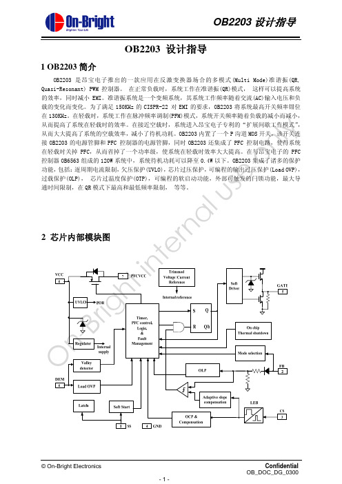
时系统工作在脉冲频率调制(PFM, pulse frequency modulation)模式,随着负载变轻,工作频率也被降
图 2. 固定输出功率,不同输入电压下开关频率
QR 系统在工作时,系统开关频率会被调制,因此调制后频谱被扩展到一个宽的范围,而定频系
统则只被调制在开关频率及其倍频的频率点上,所以 QR 系统的 EMI 系能相对于普通定频系统有较
大的改善。
■ 更高的效率 按照上述的 QR 系统的工作原理可知,新的开关周期触发正好在漏极谐振电压的某个谷底开始,
过载保护(OLP), 芯片过温度保护(OTP),可编程的软启动功能,外部可触发的闩锁功能,最大导
e 通时间限制,在 QR 模式下最高和最低频率限制, 等等。 On-Bright internal us 2 芯片内部模块图
© On-Bright Electronics -1-
Confidential OB_DOC_DG_0300
软启动功能可以降低系统启动过程中功率 MOSFET 的电压应力。OB2203 提供了可编程软启动
te (soft start)功能。每次系统重新启动都会经历软启动过程, 当 VDD 电压达到 UVLO(OFF)时,
10uA 电流从 SS 脚流出对外接电容进行充电, 在此过程中流过功率 MOSFET 的峰值电流从 0 开始逐
Confidential OB_DOC_DG_0300
OB2203 设计指导
5.2.5 消磁检测(Demagnetization) 主电感消磁检测是通过辅助绕组 n3 来实现的,如图 6 所示。辅助绕组 n3 通过分压比例电阻 R1
Omega B-227UFM 爆破防护电子壳压力传感器说明书
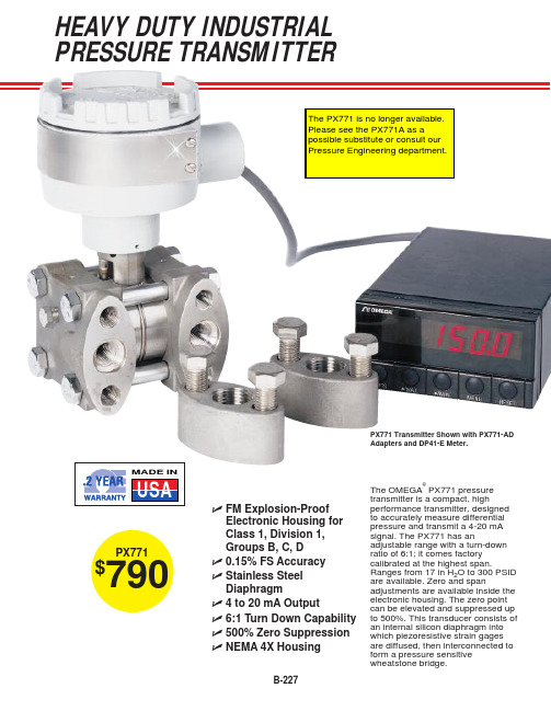
B-227ߜFM Explosion-Proof Electronic Housing for Class 1, Division 1,Groups B, C, Dߜ0.15% FS Accuracy ߜStainless Steel Diaphragmߜ4 to 20 mA Outputߜ6:1 Turn Down Capability ߜ500% Zero Suppression ߜNEMA 4X HousingPX771$790PX771 Transmitter Shown with PX771-AD Adapters and DP41-E Meter.The OMEGA ®PX771 pressure transmitter is a compact, highperformance transmitter, designed to accurately measure differential pressure and transmit a 4-20 mA signal. The PX771 has anadjustable range with a turn-down ratio of 6:1; it comes factory calibrated at the highest span.Ranges from 17 in H 2O to 300 PSID are available. Zero and spanadjustments are available inside the electronic housing. The zero point can be elevated and suppressed up to 500%. This transducer consists of an internal silicon diaphragm into which piezoresistive strain gages are diffused, then interconnected to form a pressure sensitivewheatstone bridge.HEAVY DUTY INDUSTRIAL PRESSURE TRANSMITTERThe PX771 is no longer available. Please see the PX771A as a possible substitute or consult our Pressure Engineering department.FOR GAGE, DIFFERENTIAL AND VACUUM MEASUREMENTSCANADA www.omega.ca Laval(Quebec) 1-800-TC-OMEGA UNITED KINGDOM www. Manchester, England0800-488-488GERMANY www.omega.deDeckenpfronn, Germany************FRANCE www.omega.frGuyancourt, France088-466-342BENELUX www.omega.nl Amstelveen, NL 0800-099-33-44UNITED STATES 1-800-TC-OMEGA Stamford, CT.CZECH REPUBLIC www.omegaeng.cz Karviná, Czech Republic596-311-899TemperatureCalibrators, Connectors, General Test and MeasurementInstruments, Glass Bulb Thermometers, Handheld Instruments for Temperature Measurement, Ice Point References,Indicating Labels, Crayons, Cements and Lacquers, Infrared Temperature Measurement Instruments, Recorders Relative Humidity Measurement Instruments, RTD Probes, Elements and Assemblies, Temperature & Process Meters, Timers and Counters, Temperature and Process Controllers and Power Switching Devices, Thermistor Elements, Probes andAssemblies,Thermocouples Thermowells and Head and Well Assemblies, Transmitters, WirePressure, Strain and ForceDisplacement Transducers, Dynamic Measurement Force Sensors, Instrumentation for Pressure and Strain Measurements, Load Cells, Pressure Gauges, PressureReference Section, Pressure Switches, Pressure Transducers, Proximity Transducers, Regulators,Strain Gages, Torque Transducers, ValvespH and ConductivityConductivity Instrumentation, Dissolved OxygenInstrumentation, Environmental Instrumentation, pH Electrodes and Instruments, Water and Soil Analysis InstrumentationHeatersBand Heaters, Cartridge Heaters, Circulation Heaters, Comfort Heaters, Controllers, Meters and SwitchingDevices, Flexible Heaters, General Test and Measurement Instruments, Heater Hook-up Wire, Heating Cable Systems, Immersion Heaters, Process Air and Duct, Heaters, Radiant Heaters, Strip Heaters, Tubular HeatersFlow and LevelAir Velocity Indicators, Doppler Flowmeters, LevelMeasurement, Magnetic Flowmeters, Mass Flowmeters,Pitot Tubes, Pumps, Rotameters, Turbine and Paddle Wheel Flowmeters, Ultrasonic Flowmeters, Valves, Variable Area Flowmeters, Vortex Shedding FlowmetersData AcquisitionAuto-Dialers and Alarm Monitoring Systems, Communication Products and Converters, Data Acquisition and Analysis Software, Data LoggersPlug-in Cards, Signal Conditioners, USB, RS232, RS485 and Parallel Port Data Acquisition Systems, Wireless Transmitters and Receivers。
Mathcad - OB2273AMP变压器设计步骤
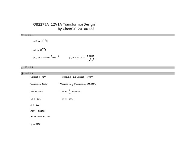
1 Pin
Iinavg 3
0.056 A
Vacmin
参考其它算法: 最大占空比:
Dmax1
n(Vo Vf )
0.41
Vdcmin n(Vo Vf )
参考其它算法: 变压器原边峰值电流: Ipkc 2Pin 0.617 A
Vdcmin0.45
Ipk1 2Iinavg 0.257 A Dmax
输出二极管反向耐压 (漏感尖峰100V左右,按120V计算)
Vf 0.55V
输出二极管正向导通压降
Step2 :匝比选择
0.8Vrd Vinmax Vo n
n Vinmax 0.8Vrd Vo
0.8Vmos n(Vo Vf ) Vinmax
Vdcmax 5.49 0.8Vrd Vo
次级电感感量:
Ls2 (Vo Vf )(1 Dmax) 0.039 mH FswΔIsbcd
初级电感感量:
Lp2 Ls2n2 1.404 mH
CCM时副边峰值电流: ΔIsp Io ΔIsbcd 3.167 A 1 Dmax 2
CCM时原边峰值电流: ΔIpp ΔIsp 0.528 A n
Ipa Ipk2 ΔIp2 0.386 A 2
原边电流直流分量: Ipdc DmaxIpa 0.167 A
原边电流有效值: Iprms Ipa Dmax 0.254 A
原边电流交流分量: Ipac Ipa Dmax(1 Dmax) 0.191 A
副边电流直流分量: Isdc 1A
最小匝比
n 0.8Vmos Vinmax Vo Vf
0.8Vmos Vdcmax 11.685 Vo Vf
最大匝比
参考其它算法: Vmos 170V Vdcmax 8.498 Vo Vf
OB2273 Preliminary Datasheet_乐科_110323(1)
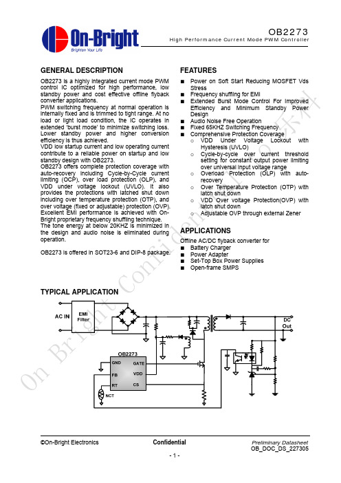
control IC optimized for high performance, low
Stress
standby power and cost effective offline flyback ■ Frequency shuffling for EMI
converter applications. PWM switching frequency at normal operation is internally fixed and is trimmed to tight range. At no load or light load condition, the IC operates in extended ‘burst mode’ to minimize switching loss. Lower standby power and higher conversion efficiency is thus achieved. VDD low startup current and low operating current contribute to a reliable power on startup and low standby design with OB2273. OB2273 offers complete protection coverage with
Con TYPICAL APPLICATION
Bright
On
©On-Bright Electronics
Confidential -1-
Preliminary Datasheet OB_DOC_DS_227305
OB2273
High Performance Current Mode PWM Controller
2273中文操作手册

3MTM DynatelTM 2250/2273M
1
目录
一、手册简介 ........................................................... 4 二、快速入门 ............................................................................................................. 4
1. 电池安装 ........................................................................................................ 4 2. 设置接收器时钟 ............................................................................................. 5 3. 发射器键区和连接说明 .................................................................................. 6 4. 接收器键区和接口说明 .................................................................................. 8
2
3MTM DynatelTM 2250/2273M
六、电子标识器和 EMS-iD 标识器 ........................................................................... 27 1. 启动/关闭标识器类型 ................................................................................ 27 2. EMS 标识器的定位 ...................................................................................... 27 3. 标识器深度估测 ........................................................................................... 30 4. 读取 iD 标识器 .............................................................................................. 32 5. 对 iD 标识器进行信息输入 ............................................................................ 33 6. 预编程标识器的数据编辑 ............................................................................. 35 7. 查看标识器历史记录 .................................................................................... 36 8. 创建/编辑 iD 标识器模板 ............................................................................ 38
M5573替换GR8837,OB2263,OB2273
描述M5573是一款优化的高性能高集成的用于反激式变换器的电流模式PWM控制芯片,具备低待机功耗和低成本的优点。
正常工作下,PWM开关频率通过外部电阻可调。
在空载或轻载条件下,IC就会工作在“跳周期模式”来减少开关损耗,从而实现低待机功耗和高转换效率的实现。
M5573提供全面的保护,包括自动恢复保护,逐周期电流限制(OCP),过载保护(OLP)、带迟滞功能的VDD欠压保护,和过电压(固定或可调的)保护(OVP)。
M5573频率抖动能实现优良的EMI性能。
M5573在工作中消除了低于20kHz音频噪声的消除。
M5573采用SOT-23-6封装。
典型应用图典型应用图特征软启动功能,减少应力功率MOSFETVDS降低EMI频率抖动功能跳周期模式控制的改进,提高效率降低待机功耗最小功率的备用电源设计消除音频噪声开关频率通过外部电阻可调综合保护性能1.带迟滞功能的VDD欠压保护2.逐周的过流阈值设置,在全电压范围内恒定输出功率3.过载保护(OLP)与自动恢复4.自动恢复的VDD过压保护(OVP)应用领域适用于AC/DC反激式变换器手机充电器,上网本充电器笔记本适配器机顶盒电源各种开放式开关电源引脚功能描述绝对值范围芯片框图应用信息M5573是一款优化的高性能高集成的用于反激式变换器的电流模式PWM控制芯片,具备低待机功耗和低成本的优点,扩展模式大大降低了待机功耗,方案设计适应国际节能的要求。
●启动电流和启动控制M5573启动电流非常低,便于获取高于VDD的UVLO值并迅速启动。
因此,高阻值启动电阻可减少功率损耗,并能在应用中稳定可靠的启动。
●工作电流M5573工作电流低至1.4mA。
跳周期模式与工作电流一起扩展能实现较高效率。
●软启动M5573在通电时触发一个4ms的软启动来降低启动时的应力。
当VDD达到VDD_O,SE尖峰电压由0.15V逐渐升高增至最大。
每次重启后都会重新软启动。
●频率抖动干扰的改进M5573集成了频率抖动(开关频率调制)功能进行扩频,最大限度地降低了EMI带宽,简化了系统设计。
OB2273替代资料大全

OB2273是一款高度集成的电流模式PWM控制IC的高性能,低待机功耗(小于100mW)和成本效益的离线反激式转换器应用进行了优化。
它提供完整的保护范围内的自动恢复功能包括逐周期电流限制(OCP),过载保护(OLP),VDD欠压锁定(UVLO)。
它也提供了保护与锁存关闭包括过温保护(OTP),过电压(固定或可调)保护(OVP)。
OB2273特点:电源,软启动,减少MOSFET的VDS应力为EMI的频率抖动扩展突发模式(Burst Mode)控制以提高效率和最低的待机功耗设计音频无噪音运行固定的65kHz开关频率全面保护的覆盖面VDD与滞后欠压锁定(UVLO)循环周期过流阈值设置为恒定输出功率限制在通用输入电压范围自动恢复过载保护(OLP)过温保护(OTP),锁存关闭 VDD过电压保护(OVP),锁存关闭通过外部稳压可调过压保护(OVP)可提供SOT23-6和DIP8封装,符合RoHS标准OB2273 应用范围:离线AC / DC反激式转换器LED显示器电源供应器上网本/平板电脑适配器电池充电器电源适配器开架式开关电源M5573可完全替代OB2273,在参数和性能上二者完全一致,我们来看看M5573的相关参数:M5573是一款高度集成的电流模式PWM 控制器,专为高性能、低待机功耗、低成本、高效率开关电源系统设计。
M5573在空载或者轻载状态下可以工作于跳周期模式,由此取得低待机功耗与高转换效率。
M5573 在启动和工作时只需要很小的电流,以此来减小待机时的功耗。
M5573内置多种保护,包括:逐周期电流限制(OCP)、VCC欠压保护、过载保护(OLP)。
此外:过热保护(OTP)、(固定或可调)、VDD 过压保护(OVP) 带有自恢复功能。
电路有优良的EMI 性能,消除了低于20KHz的音频噪声。
特点:开机软启动可降低MOSFET 的Vds 压力改善EMI 的频率抖动改善效率和待机功率最小化的扩展burst 模式设计无音频噪声工作固定的65KHz 开关频率逐周期电流限制(OCP)VCC欠压保护可自动恢复过载保护(OLP)可自动恢复过热保护(OTP)可自动恢复VDD 过压保护(OVP)通过外接稳压管可调节OVP封装:SOT23-6产品应用:离线式AC/DC 反激变换器●手机充电器, 上网本充电器●笔记本适配器●机顶盒电源●各种开放式开关电源M5573替换型号OB2273,低成本、低功耗、高效率详情见PDF资料——。
- 1、下载文档前请自行甄别文档内容的完整性,平台不提供额外的编辑、内容补充、找答案等附加服务。
- 2、"仅部分预览"的文档,不可在线预览部分如存在完整性等问题,可反馈申请退款(可完整预览的文档不适用该条件!)。
- 3、如文档侵犯您的权益,请联系客服反馈,我们会尽快为您处理(人工客服工作时间:9:00-18:30)。
2.引脚说明:OB2273 封装形式SOT23-6
管脚名称管脚编号VDD RT FB GATE GND CS
NCT
OB2273
OB2273 系统工作模式示意图
OB2273 采用在重载条件下采用固定频率工作模式。
随着负载降低,进入降频工作模式,提高轻载效率;在负载较轻或空载时,系统进入间歇工作模式,从而降低功耗。
各模式的切换通过系统反馈电压FB来控制,如上图所示:
Current-Mode PWM OB2273
RT 仅作为RT仅作为
OVP Latch protection RT作为OTP and OVP Latch protection
optional
Current-Mode PWM OB2273
Current-Mode PWM OB2273 (1)(2) (3)
快速启动电路
⑤
①
②③
⑥
⑦④
案例一(40W):100mW设计关键点
Current-Mode PWM OB2273系统高低压补偿设计电路
Current-Mode PWM OB2273普通反馈补偿电路
增加极点反馈补偿电路
Current-Mode PWM OB2273
20V
264Vac:SCP,saturation voltage (Vds_sat) is high. Cs pin RC设计
Add RC circuit to reduce drain saturation voltage across MOS.
CS pin R*太大造成Vds冲高现象
从上图FB(红色)波形,可以看到环路加快,从而避免了Vds冲高现象
Current-Mode PWM OB2273
Current-Mode PWM OB2273说明:1)100mW以下方案设计,效率>87%.
Current-Mode PWM OB2273
Thank you !。