天线设计软件4nec2的简易教程
【设计】24G天线设计完整指南原理设计布局性能调试

【关键字】设计本文章使用简单的术语介绍了天线的设计情况,并推荐了两款经过测试的低成本PCB天线。
这些PCB天线能够与PRoC?和PSoC?系列中的低功耗蓝牙(BLE)解决方案配合使用。
为了使性能最佳,PRoC BLE和PSoC4 BLE2.4GHz射频必须与其天线正确匹配。
本应用笔记中最后部分介绍了如何在最终产品中调试天线。
1、简介天线是无线系统中的关键组件,它负责发送和接收来自空中的电磁辐射。
为低成本、消费广的应用设计天线,并将其集成到手提产品中是大多数原装设备制造商(OEM)正在面对的挑战。
终端客户从某个RF产品(如电量有限的硬币型电池)获得的无线射程主要取决于天线的设计、塑料外壳以及良好的PCB布局。
对于芯片和电源相同但布局和天线设计实践不同的系统,它们的RF(射频)范围变化超过50%也是正常的。
本应用笔记介绍了最佳实践、布局指南以及天线调试程序,并给出了使用给定电量所获取的最宽波段。
图1.典型的近距离无线系统设计优良的天线可以扩大无线产品的工作范围。
从无线模块发送的能量越大,在已给的数据包错误率(PER)以及接收器灵敏度固定的条件下,传输的距离也越大。
另外,天线还有其他不太明显的优点,例如:在某个给定的范围内,设计优良的天线能够发射更多的能量,从而可以提高错误容限化(由干扰或噪声引起的)。
同样,接收端良好的调试天线和Balun(平衡器)可以在极小的辐射条件下工作。
最佳天线可以降低PER,并提高通信质量。
PER越低,发生重新传输的次数也越少,从而可以节省电池电量。
2、天线原理天线一般指的是裸露在空间内的导体。
该导体的长度与信号波长成特定比例或整数倍时,它可作为天线使用。
因为提供给天线的电能被发射到空间内,所以该条件被称为“谐振”。
图2. 偶极天线基础如图2所示,导体的波长为λ/2,其中λ为电信号的波长。
信号发生器通过一根传输线(也称为天线馈电)在天线的中心点为其供电。
按照这个长度,将在整个导线上形成电压和电流驻波,如图2所示。
NEC教程
天线仿真培训班第一讲4NEC2天线仿真软件安装4NEC2天线仿真软件,是美国海军使用的一个天线仿真软件,由于其功能比较简单,能够帮助天线设计者,提供一个大概的天线设计方向。
所以这个软件在国外天线爱好者应用比较广泛。
这个天线分4NEC2和NEC2X两个部分,其中4NEC2用于天线设计,4nec2x用于三维方向图察看,另外还有一个工具软件Build这个软件为设计者提供一个板式,螺旋式,球形等模型。
软件使用环境:计算机n270,内存1G均可,如果档次高一些,再做天线优化时,速度要快一些。
其他没有什么要求。
这个软件没有汉化,英语好的朋友学习起来要快一些,英语差的朋友也不要紧和我一起慢慢学,说不定你一定能成大师。
第二讲引言1.编辑4nec22.4nec2是什么3.天线建模4.词汇表4nec2软件是基于Windows操作系统的天线仿真、制作软件,有可视化,优化和验证二维或三维几何结构功能,并且还有可视化和比较辐射图和表。
4Nec2也是一个很简单的图形界面软件便于用户直观使用,用户可以直观的采用几何建模和数据建模,并可以进行数据管理和对仿真结果进行分析。
其优化后的结果与实际制造基本一致。
4nec2仿真软件是由NEC公司为美国海军开发一个天线仿真计算程序。
4nec2天线仿真软件最大的优点是可以进行图片式可视化操作,比如可以进行一个“几何形状设计”,如抛物面天线,螺旋天线,球形天线,方框天线等,非常容易建立模型。
本软件还包括其他模块,如以阻抗匹配、史密斯圆图、二维和三维天线方向图及天线增益等。
这个天线仿真软件是一个免费的共享软件。
我们在学习前,先举一个偶极子天线实例我们首先提出来模拟一个半波偶极子,共振频率在:14.175mhz,波长:20米。
用3毫米直径的铜作辐射体,平等于地面。
我们如何在14.175这种频率下情况工作呢?根据天线理论:L=0.95X(入/2)=10.05m我们在编辑器中画出天线长度,(坐标的X,Y和Z是笛卡尔坐标)。
漫谈长城天线的巴伦(修订版)
漫谈长城天线的巴伦我翻译的系列长城天线的文章——阿摩司天线系列发布之后,很多网友给我发短消息,询问巴伦的问题。
常常看到很多关于巴伦的文章,大都是各处抄来的,特别是很多例子和图纸都是从短波火腿论坛照搬来的,有的是从电视论坛转抄来的,东拼西凑,逻辑性不强,前言不搭后语的情况时有发生,让人看着如坠雾中,理解起来十分困难。
最主要的是,网友的这些实践,大都是集中在短波或者超短波领域,比如电视天线用磁芯做巴伦,在2.4G的WIFI频段并不适用,当然也就不适用于长城天线。
所以,这段时间,恶补了一下关于巴伦的知识,特别是翻阅了大量的高校教科书,大有收获。
不敢独享,下面仅就长城天线的巴伦向坛友汇报自己的学习体会。
业余无线电通信中常用到的巴伦,主要指的是同轴电缆向天线馈电时所需要的不平衡到平衡的变换器,英文是Balance—Unbalance组合,缩写为一个新词:Balun,音译为巴伦。
我们知道,我们平常应用的很多天线,半波振子天线、折合振子天线、环行天线等都是平衡馈电的,它们都有两个馈电点,这两个馈电点的信号电压(或电流)的相位是互为反相的。
而主馈电缆常常都是用同轴电缆,同轴电缆属于不平衡(不对称)馈线,其内导体是馈电点,而外导体是地线点,不参与馈电。
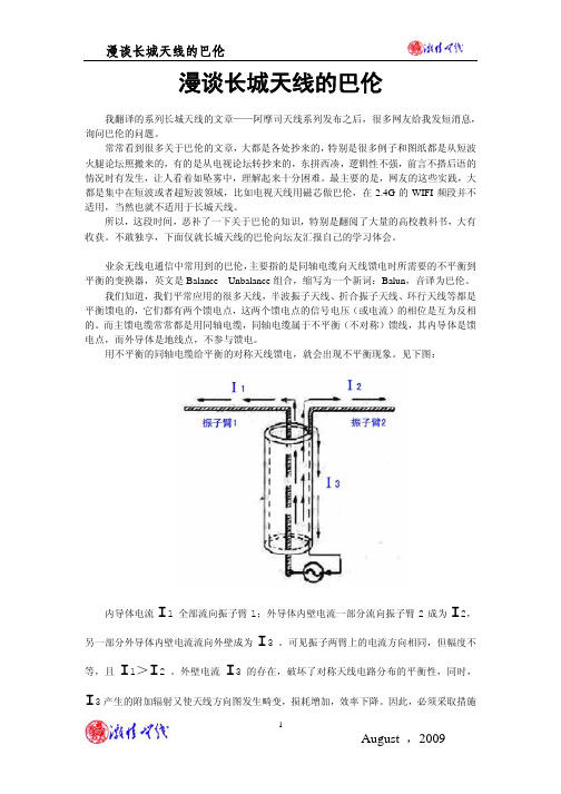
用不平衡的同轴电缆给平衡的对称天线馈电,就会出现不平衡现象。
见下图:内导体电流I1 全部流向振子臂1;外导体内壁电流一部分流向振子臂2成为I2,另一部分外导体内壁电流流向外壁成为I3 。
可见振子两臂上的电流方向相同,但幅度不等,且I1>I2 。
外壁电流I3 的存在,破坏了对称天线电路分布的平衡性,同时,I3产生的附加辐射又使天线方向图发生畸变,损耗增加,效率下降。
因此,必须采取措施抑制同轴电缆外导体外侧的电流,使I3≈0 。
巴伦就承担了把不对称传输转化为对称传输的任务。
上图就是长城天线常用的巴伦——U形管变换器。
同轴电缆内导体在a点直接和天线振子的左臂相连,然后由a点经过弯折成U型的、长度为λg/2的一段同轴电缆(λg是同轴电缆内的波长),在b点与天线振子的右臂连接。
菱形天线制作方法

菱形天线制作方法
制作一个菱形天线的方法如下:
材料:
- 电缆
- 两个金属导线
- 电缆剪刀
- 卷尺
步骤:
1. 切割电缆:使用电缆剪刀将电缆切成所需长度。
具体长度根据天线设计和使用环境而定。
2. 切割导线:使用电缆剪刀将金属导线切割成两条相等长度的线段。
3. 制作菱形形状:将电缆两端连接在一起,形成一个圆圈。
然后将金属导线的两端分别连接在电缆圈的两个相对位置上,形成一个菱形形状。
确保金属导线与电缆之间没有松动或空隙。
4. 测试天线:将天线连接到无线设备的天线接口上,如无线路由器或电视机。
打开设备,并测试其无线信号质量。
根据需要,调整菱形天线的位置或方向,以获得最佳的无线信号。
请注意,这只是制作菱形天线的一种简单方法。
对于更复杂的设计,可能需要更多的材料和工具,并且可能需要更多的知识和专业技术。
如果您对天线制作不熟
悉,建议寻求专业人士的帮助或购买现成的天线。
4NEC2天线设计软件英文教程

Simulation of Wire Antennas using4NEC2A Tutorial for BeginnersVersion 1.0Author:Gunthard Kraus,OberstudienratEmail: mail@gunthard-kraus.deHomepage : www.gunthard-kraus.deConsultant:Hardy Lau, Dipl.-Eng. (DH)Duale Hochschule Baden Württemberg (DHBW), Friedrichshafen, GermanyAugust 12th, 2012Content Page1. Introduction 32. Installation 33. Getting Started 34. Geometry Builder, Geometry Editor or Text Editor to create an NEC File 45. Start with the included …example2.nec“ (300MHz Dipole) 55.1. Far Field Simulation 55.2. Coloured 3D Presentation 75.3. Opening the NEC File with Notepad 105.4. Using the 4NEC2-Editor 125.4.1. Working with the old 4NEC2 editor 125.4.2. The new 4NEC2 editor 125.5. Near Field Simulation 145.6. Sweeping the SWR and the Input Reflection 156. First own Project: 300MHz Dipole over realistic Ground 166.1. Modification in the NEC-File 166.2. Far Field Simulation 186.3. Near Field Simulation 196.4. Sweeping the SWR and the Input Reflection 207. Second Project: 300MHz Dipole using thick Wires 217.1. The thick wire problem 217.2. Far Field and Near Field 227.3. Sweeping the SWR and the Input Reflection 237.4. Sweeping the Antenna Gain 237.5. Sweeping the Input Impedance 258. A wonderful toy: the Smith Chart Machine 269. Optimizing (Key F12) 279.1. Optimizing the Antenna Length (thick wire dipole of chapter 7) 279.2. Parameter-Sweep 2910. Third Project: Geometry Builder or Text Editor to design aHelix Antenna? 3110.1. Fundamentals of Helix-Antenna Design 3110.2. Design using the Geometry Builder 3210.3. Far Field Simulation 3310.4. Frequency Sweep of Gain and Impedance 3310.5. Once more the same procedure, but now using the Notepad-Editor 3410.6. Once more: Far Field Simulation 3610.7. Once more: Frequency Sweep of Gain and Impedance 3710.8. Feeding the Antenna by a short piece of wire 37 Appendix:A short Overview of the most important and mostly used NEC Cards1. IntroductionNEC (= Numerical Electric Code) is a simulation method for wire antennas, developed by the Lawrence Livermore Laboratory in 1981 or the Navy. To realize this an antenna is divided into “short segments” with linear variation of current and voltage (like SPICE when simulating circuits). The results are very convenient and the standard for this simulation technique is NEC2.Time is running and so the weaknesses of NEC2 (e. g. simulation errors when wires are crossing in a very short distance or when using buried wires) were overcome with 4NEC2. But 4NEC2 was top secret for a long time, no export allowed and still today very expensive (= starting at 2000$). So a normal private user will take NEC2 and has the choice between lots of offers in the Internet. The two leaders are EZNEC (= not free of charge) and4NEC2 (= completely free).Especially 4NEC2 offers a huge amount of possibilities and options (including graphical 3D display of the results) and was programmed by Arie Voors. Its main advantages are the optimizing tools and the parameter sweeps. It can be found and downloaded free of charge from the Internet.Two program packages must be installed: first …4NEC2.zip“ and afterwards …4NEC2X.zip“ i n the same directory.…4NEC2“ is the NEc calculator but …4NEC2X“ (= 4NEC2 Extended) offers after pressing F9 the mentioned coloured 3D presentation of the simulation results with a lot of features.Please note:4NEC2 is an unbelievable huge tool with infinite possibilities. So this tutorial wants to “open a door” and so the user gets the necessary fundamental information about the usage of the software. He has then to continue itself….2. InstallationNo problem: after the download (http://home.ict.nl/~arivoors/) unzip the package and start the 4NEC2 exe file. After the successful installation right click on the 4NEC2X – exe file and install this software in the same directory. The software is completely free and no licensing necessary. Bugs or proposals for improvements can be mailed to the author Arie Voors who has done a huge work. So tell him …Thank you“ in the mail for his work.3. Getting StartedClick on the 4NEC2X icon and you get two windows on your screen:Main (F2) andGeometry (F3)After the simulation two additional windows can be opened:Pattern (F4) andImpedance / SWR / Gain (F5).:Remarks:a) Input and property inputs, modifications and start of simulation are all done in the Main window.b) The antenna geometry is shown in the Geometry window due to the Input NEC File.c) Far field and near field simulation results are presented in the Pattern window.d) And finally when sweeping you can see the impedance or the SWR or the F/B ratio versus frequency bypressing F5.4. Geometry Builder, Geometry Editor or Text Editor to create a NEC File?This must be decided by the user who has the choice.a) Creating the NEC file with the Geometry Builder is fine. For Patch-, Plane-, Box-,Helix-, Spherical-, Cylinder- or Parabolic structures there exist own menus with own screens and the usage is really simple. But you have only the listed 7 antenna types…b) To create any desired structure is an affair for the Geometry Editor. This editor this mainly foreseen for beginners and is easy of use.The next 3 editors concentrate directly on the NEC file, because this is the goal of all preparation for the simulation. That needs more effort for the user but gives more options for simulation and optimizing.But remember:All length values in a NEC File are always read as …Meters“. Otherwise you must write an additional “GS” card with a scaling factor for correction (example: entries in Inches…) which is applied to the complete structure.But now let’s have a look at the 3 editors:With a simple text editor like Notepad you have to write the pure NEC file and / or modify entries in it. So the complete antenna structure must exist in your brain before writing -- but this is the fastest and most effective way.That is not difficult and after a short time you are familiar with this method. Then you are able to modify structures or parts of them in a hurry….The …old 4NEC2 – Editor“ was a progress because of using buttons to separate the different parts of the NEC file (but today no longer used and maintained).e) the …new 4NEC2-Editor“ uses menus with lines and columns for the different entries. Very fine -- but the user with lot of experience misses now the direct view on the complete NEC file. So after some time of working with4NEC2 nearly everybody returns to Notepad.....In the following examples and projects all these different editor methods are demonstrated. So please examine and decide yourself.5. Starting with the included “example2.nec“ (300MHz Dipole)5.1. Far Field SimulationPlease change to the folder “models“ and open the “example2.nec” file.In the left (= Main) window you find the simulation frequency and wavelength (= big red circle). The small red circle in the under left corner of the window indicates that the dipole is divided into 9 segments. The right window shows the dipole geometry in the related coordinate system.Now press the F7 button (= start of calculation) andchoose …Far Field pattern“, “Full“ and “Generate“.An arc resolution of 5 degrees will do the job for the firsttime, giving short calculating times.Then press “Generate”.This is the success and the main window is now fulfilled with entries and data. Now Press F4 and the vertical radiation pattern is shown in an additional window.The …Show “ menu in the Pattern (F4) window offers several options. With “Next pattern” and Previous pattern” you can walk through the diagrams.Pressing …Indicator “ gives an additional radial cursor for the diagram. If you left click on any point of the pattern curve with the mouse the cursor snaps to this point and the values of this point are indicated.Under “Far Field“ can be found:a) The switch for changing to the Horizontal Plane.b) The option to change to the …ARRL-style scale“,using a logarithmic scaling for the amplitudeincluding an …automatic scaling spread“. So all lobesof a pattern are visible without efforts.c) “Multi Pattern“ shows all diagrams for chosenpolarity.d) “Bold lines“ gives thick lines of the curves ande) “Font scaling“ is self explaining.f) At last you can switch the azimuth angle (Phi) and /or the elevation angle (Theta) forward or reverse.The rest of the menu should be tested by yourself.5.2. Coloured 3D PresentationThis option needs …4NEC2X“. So please start your work in the future always by opening this program.Close 4NEC2 and start4NEC2XUse again the…example2.nec“ file andrepeat the far fieldsimulation. Then select F9to start the 3D Viewer andyou will get this screen.Now press the left mousebutton when rolling yourmouse -- this varies theazimuth and elevationangle of the diagram(…for you the result is likea flight in a helicopteraround the antenna…).Now play a little bit with the following buttons:a) …Ident“ is used to identify and to mark a desired segment after entering the segment number.b) …Res“ = “Reset“ to the start position after the invoke of the 3D presentation.c) “Rotc“ is used to define a segment as rotation centre.d) …Col“ invokes the colour menu .Let us continue with the proposed 3D presentation of the antenna’s radiation.Chose these settings….…and you get this screen. The pattern can be rotated like before by using the mouse.Here follow some presentations which are of interest for a lot users:At first the current distribution on the antenna wire……or additionally the phase distribution.Or all the segments of the wire can be made visible:Play now yourself with this huge amount of possibilities…but this takes time….5.3. Opening the NEC-File with the Notepad EditorChange to the Main menu (F2), open “settings” and chose notepad-editor . Then press F6 to open the NEC file of our antenna.Please do not jump over this chapter, because a deep analysis of the NEC file details helps to modify or to optimize or to analyse error messages.Every line starts with a short abbreviation (= card name) and describes in a short form the task of the line.Attention:In the main window you find a “NEC short reference“ in the help menu.Now let us examine every line.Line 1 and line 2: “CM “ starts a comment line with a maximum of 30 signs.---------------------------------------------------------------------------------------------------------------------------------------- Line 3: “CE “ is “End of comment “----------------------------------------------------------------------------------------------------------------------------------------- Line 4: “SY “ stands for a “Symbol“ and this is always a Variable (here: length = len=0.4836).Caution: all length values in a NEC file are given and calculated in Meters.Corrections can be made by using an additional “GS” card (= geometry scaling) e. g. when using feet instead of meters. This scaling factor is applied to the complete structure.--------------------------------------------------------------------------------------------------------------------------------------- Line 5: “GW “ =…Geometry of wire“. Let us have a detailed look at the entries of this line. The line starts with “1“ (= “Wire number 1“). “9“ indicates that the wire is divided into 9 Segments . “0 / -len/2 / 0“ are the xyz coordinates of the wire’s starting point . Length unit isalways “Meter“.“0 / len/2 / 0“ are the xyz coordinates of the wire’s end point . “.0001“ is the wire’s radius in Meters .------------------------------------------------------------------------------------------------------------------------------------ Line 6: …GE“ = end of “geometry information “, followed by a number which describes theground“0“ means: no ground = free space.“-1“ or “1“ represent a ground, but the details must be entered in a separate “Ground card“ (= GN card).------------------------------------------------------------------------------------------------------------------------------------Line 7: …LD“ = …Loading of a segment“. Please use the NEC short referenceand the NEC manual in the online help to find out all options.“5” = in this example only “LD 5“ is used to enter the conductivity of the antenna wire.“1” = Wire 1.…0 0“ = two empty fields.…5.8001E7“ is the conductivity for copper ( in mhos).----------------------------------------------------------------------------------------------------------Line 8: “EX“ = “Exitation“.“0“ = a voltage source is used for excitation.“1“ = wire 1 (= tag 1) is excited“5“ = excited segment of Wire 1.“0“ = an empty field.…1 0“ = real and imaginary part of the applied complex voltage (1 + j0).So in this case a real voltage of 1V is used----------------------------------------------------------------------------------------------------------Line 9: “FR“ = frequency information.Normally a sweep is used and must be programmed. So some information is necessaryif only a fixed frequency is used:“0“ = linear frequency sweep (“1“ gives a logarithmic sweep)“1“ = only one frequency step is foreseen.“0 0“ = two empty fields.“300“ = start value of frequency = 300MHz.“0“ = gives a frequency step width of Null MHz---------------------------------------------------------------------------------------------------------Line 10: “EN“ = end of NEC file---------------------------------------------------------------------------------------------------------5.4. Using the 4NEC2EditorCaution:As already mentioned you have the choice between an old and a new version (…you find them in the “Settings” of the Main menu).5.4.1. Working with the old 4NEC2 EditorNo problem, it’s like working with Notepad in a modern environment. But this editor version is obsolete.------------------------------------------------------------------------------------------------------------------------------------------------------- 5.4.2. The new 4NEC2 EditorThe editor can either beinvoked by pressing<Control> + <F4> or byopening “Settings” in themain menu followed by“Edit / Open Input NECFile”.This is the first card named“Symbols”.All the used wires and their properties are listed on the next card “Geometry“ (Tag Number / number of segments / xyz coordinates of wire start and end / radius of wire in Meters).---------------------------------------------------------------------------------------------On the Source / Load card must be noted that a real voltage source (magnitude = 1V) is connected to Tag 1 / Segment 5.(Remember: In the load card “LD” in the true NEC file there was only one entry the value of the conductivity of the copper for the wire).At last information about frequency andsweeping must be entered. No problemfor a fixed frequency simulation at300MHz and a dipole in free space.----------------------------------------------------------------------------------------------------------------------------------------5.5. Near Field SimulationOpen main“ (F2) and press “F7“. Then choose “Near Field Pattern“and “E-Field“ and check the entries. This is the task:Show the E Field distribution for Y = 0 (= centre of dipole as seen inthe direction of the antenna wire and step…X“ from -20m to +20m in steps of 1,6mand…Z“ from 0 to 50m in steps of 2m.“This is the simulation result.Important:The scaling of the field distribution belongs to anInput Power of 100W (See the “Settings” menu andthen …Input Power“ for changing)(Remember:This power value is also used when simulating thecurrent distribution on the antenna wire).5.6. Sweeping the SWR and the Input ReflectionPress F2, then …F7. Select “Frequency sweep“.Enter the sweep range from 295 to 305 MHz in the lower half of themenu. Use a step width of 0.1MHz.Select …Ver“ (= Vertical Pattern) and start the Simulation with the button“Generate“.Simulation result:6. First own Project: 300MHz Dipole over realistic Ground6.1. Modification in the NEC-FileThe easiest way is to use the NEC file of the last example and to modify it:a) now the dipole hangs 1m above the ground andb) a realistic ground shall be used.At first create a new folder for own projects (e. g. “own_examples “) and in it an additional folder this task (“dipole_over_ground “). Then copy the NEC file of the last example into this new folder and rename it todipole_over_ground.necThen start 4NEC2X and select the new 4NEC2 editor in the settings menu. Open the new file “dipole_over_ground.nec” (by pressing F6).At first enter in the geometry card the height of the dipole’s start and end point to z = 1mThen switch to “Freq./Ground”. Select “Real ground “ and “Average “. Let the field “Connect wire for Z = 0 to ground“ free.Now open the NEC file with notepadto see the modifications:The entries in the Ground card GN are easy to understand: …2“ = Sommerfeld Norton Ground.…13“ = Dielectric constant….005“ = Conductivity in mhos/mThis is now a well known procedure: Press F7, select “Far Field Pattern“ and“Full“, followed by ”Generate“.That gives this pattern for the …Vertical Plane“.Press F9 (or the 3D button in the menu bar) and you can see the 3D pattern when using the indicated settings:No problem: use these settings and at once you get the Electrical Field Strength around the dipole.Input power is 100W.6.4. Sweeping the SWR and the Input ReflectionOpen this well known F7 menu, select “Frequency sweep“ andchoose a sweep range from 295 to 305MHz with a frequency step of0.1MHz. Select “Ver” = Vertical and click on “Generate” to start thesimulation.After the (longer) calculation time we get the result. The only difference to the last chapter is an increase of1.5MHz of the frequency for minimum reflection7. Second project: 300MHz Dipole using thick wires7.1. The Thick Wire ProblemIn the last examples an ideal and infinite thin wire was used for thesimulation. But in practice the wire radius must be increased to getsome mechanical stability.When opening “Settings” in the main menu you find in …pre-definedsymbols“ an AWG (= American Wire Gauge) list. .Choose “#3“ with a diameter of 5.8mm because this gives enoughmechanical stability.Open the NEC file with the editor, enter this value and save all.So the Geometry card must now look like in the new 4NEC2 editor:Caution:Now you must open“Others“ to activate theextended kernel for thefat wire support!When checking the NEC file with Notepad you will now find an additional new card:The card is namend “EK“ (= extended kernel) and in the future this new line can also be added by hand with the Notepad editor…(Information: the new 4NEC2 editor adds this line automatically).7.2. Far Field and Near Field SimulationThere are no changescompared to chapter 6.2(far field) and to chapter 6.3(near field for an inputpower of 100W)--------------------------------------------------------------------------------------------------------------------------------------------- 7.3. Sweeping the SWR and the Input ReflectionThis is the influence of the thick wire: the frequency for minimum reflection has decreased to a value with is 10MHz lower.-------------------------------------------------------------------------------------------------------------------------------------------------7.4. Sweeping the Antenna GainAt first repeat the simulation of the vertical radiation pattern (see chapter 7.2.), but with an angle resolution of 1 degree.maximum gain is indicated as Theta =76 degrees.In the left lower corner of the diagraman azimuth angle of 360 degrees isindicated (this means that we see a“cut” through the 3D pattern at thisangle). ArrayPress F7 to enter the following options:a) Frequency sweepb) “Gain“c) Angle resolution of 1 degreed) Sweep from 280 to 310MHz with a step width of 0.2MHze) Set Theta to 76 degrees and Phi to 0 degreesNow press “Generate“.(Click off the information that in this case no “F/B” data = front toback data are available. Ignore ist and continue with “Generate”)After the simulation process we see window F5 with the SWR and the input reflection S11.Select “Show“ and “Forward Gain“ toget the diagram with gain versus thefrequency.(And in the lower diagram we see thatthe remark “no F/B data available” istrue).-----------------------------------------------------------------------------------------------------------------------7.5. Sweeping the Input ImpedanceOpen “Show“ and select “Imp / Phase”.Now the exact value of the resonant frequency can be determined to 291MHz (there X = 0).And as theory says, the input impedance has a value of 70Ω (= radiation resistance).8. A wonderful toy: the Smith Chart MachineWhen a simulation is successfully done a Smith chart symbol is highlighted in the menu bar.So we repeat the frequency sweep of the SWR and the Input reflection over a frequency range from 270 to 310MHz with a step width of 0.2MHz and press the Smith chart button. This gives the following screen:The simulated S11 is shown as black coloured curve.In the right lower corner of the screen you find the actual frequency (here. 270MHz). Use the “right” resp. “left arrow key” on the keyboard to walk through the simulated frequency range and you will here see the S11 value for this frequency.Caution:The information “Mouse” in the next line shows always the impedance value at the actual mouse cursor position (….and NOT the converted S11 value of the curve for the simulation frequency). This impedance is indicated in serial and in parallel form.Additionally we find a pink curve and a green vector running through the actual point of the S11 curve. The circle radius gives the S11 magnitude (here: 0.409) and this circle is the way on which we march when a transmission line is connected to the input of the antenna.The phase of S11 is indicated by the green vector (e the scaling on the circumference of the Smith chart).On the left of the Smith chartsome additional information isindicated (using pink pointers).Caution:At first think a horizontalseparating line betweenthe upper and the lowernomograms ( = markedin red colour).In the upper half you get therelation between the actualSWR and the SWR voltageratio.In the lower half the relationsbetween reflection loss,return loss (in dB), powerreflection coefficient andvoltage reflection coefficientare indicated.In the menu for this presentation you find “Export“ and “Import“.This can be used to produce a Touchstone file (= S parameter file) for export purpose or data saving. You have the choice between “magnitude / phase” or “dB” form. Also Z parameter files can be produced and exported. And, if you want, use this Smith chart machine to read and to present foreign (= imported) Touchstone files.9. Optimizing (Key F12)What is an antenna design worth without optimizing? This can be done after pressing F12, but some preparation is always necessary:Every antenna data (which shall be varied for optimizing) must before in the NEC file be replaced by a variable with a definite default value.9.1. Optimizing the Antenna Length (thick wire dipole of chapter 7)Task:The resonant frequency of the “thick” dipole (see chapter 7) should be 300MHz. So let us automatically vary the wire length until only the radiation resistance can be measured at the dipole’s input at 300MHz (and X = 0)Step 1:Open the NEC file with Notepad and set the default value of the variable “len” to 0.465m. So this line must now look like: SY len=0.465Step 2:This is now the NEC file:CMLoaded dipole above Sommerfeld ground CM Thick wire used (#3) CE End of commentSY len=0.465 ' Symbol: Length = 0.465m for WL/2GW 1 9 0 -len/2 1 0 len/2 1 #3 ' Wire 1, 9 segments, halve wavelength long, 1m above ground, ‘ wire gauge: #3GE -1 ‘ Geometry data entering finished. Ground used, ends of wires ‘ not connected to ground. GN ground card necessaryLD 5 1 0 0 58000000 ' Wire conductivity GN 2 0 0 0 13 0.005 ‘ Sommerfeld ground, er = 13, conductivity = 0.005 mhos / m EK ‘ Extended wire kernel used.EX 0 1 5 0 1 0 ' Voltage source (1+j0) at wire 1 segment 5. FR 0 0 0 0 300 0 ‘ No sweep, frequency = 300MHz EN ‘ End of NEC fileStep 3:At first use a frequency sweep of the input impedance from 280 to 320MHz to show the goal of optimization.Step 4:Press F12 and check whether“Optimize“ and “Default“ are setin the upper left corner of themenu. Then select the variable(by clicking in the list) whichshall be varied for optimization.In this example we have only“len” as variable and thisvariable can be activated by amouse click on its name. Butcheck whether “len” now canbe found under “Selected”.At last we set the goal ofoptimization. It is possible tooptimize more but one antennaproperty but in this case everyproperty must be combined witha figures of merit in % (bluecircle in the figure).Important:Right click on the “X-in” window with its entered value of 100% to getthis additional menu. There select “minimize” as optimization goal. At last press “Start” and wait.This is the result after 23seconds and you canpress “OK”In the center of the screen changes something and you have now the choice between “Resume” and “Update NEC-File”.Press “Update NEC-File ” to save the necessary modifications. If you now check the file by opening it with Notepad you will find a new value for the wire length with “len=0.4697”. So start a new simulation (F7) with the same frequency sweep as before.Here is the result:A fine done job!----------------------------------------------------------------------------------------------------------------------------------------9.2. Parameter-SweepOften it is of interest how some characteristic antenna data (e. g. input impedance) vary not only with frequency but also with special antenna properties (e.g. height over ground). To get a good overview in this case you can use the parameter sweep for this purpose. Here comes an example.Task:Simulate the input impedance of the thick dipole at f = 300MHz when varying the height over ground between 0.5m and 1,5m in 20 steps.Step 1:Use Notepad to open the NEC file for the following modifications:a) In the “SY” add an entry for height as a variable with a default value of 1m (hght=1).b) Replace the value of 1m in the GW card by the variable “hght”.CMExample 2 : Loaded dipole above Sommerfeld ground CM Thick wire used (#3) CE End of commentSY len=0.4697, hght=1 ‘ Symbols: Length = 0.4697m for WL/2, height = 1mGW 1 9 0 -len/2 hght 0 len/2 hght #3 ' Wire 1, 9 segments, halve wavelength long, 1m ‘ above ground, wire gauge: #3GE -1 ‘ Geometry data entering finished. Ground used, ends of wires ‘ not connected to ground. GN ground card necessaryLD 5 1 0 0 58000000 ' Wire conductivity on “Load” card GN 2 0 0 0 13 0.005 ‘ Sommerfeld ground, er = 13, conductivity = 0.005 Siemens / m EK ‘ Extended wire kernel used.EX 0 1 5 0 1 0 ' Voltage source (1+j0) at wire 1 segment 5. FR 0 0 0 0 300 0 ‘ No sweep, frequency = 300MHz EN ‘ End of NEC file。
无线软件集合(包含BT4中文版)

找工作,上东莞英才网在WINDOWS 系统里利用VMware虚拟机启动BT3或者BT4 “学习”无线WEP和WPA 傻瓜版教程!集成spoonwep2和spoonwpa的BT4中文版下载地址:收费附件: BT4中文版.rar支持迅雷高速下载官网下载原版BT3和BT4光盘ISO文件,不带spoonwep2和spoonwpa下载: btbt3-final.iso下载: bt4-beta-isoWPA破解全攻略.pdf (2.26 MB)BT3研究学习无线WEP和WPA增加版教程.pdf (1.94 MB)从零开始,教你如何破解WEP、WPA无线网络.doc (3.18 MB)包含WEP无客户端情况下采用主动注入的方式P解aircrack-ng_1.0~rc1-2ubuntu1_i386.rar (1.19 MB)aircrack-ng-svn-trunk-current.tar.gz (1.3 MB)Aircrack命令组详解《一》Airbase-ng.pdf (413.37 KB)BT4硬盘安装助手.rar (1.34 MB)由于分辨率问题10寸屏的上网本无法显示全。
软件运行后首先会跳出一个我的广告,点击软件右下角的开始安装出现自动安装界面。
如下图设置就可以了!简单制作U盘版BT4制作U盘版BT4工具.part1.rar (3.91 MB)制作U盘版BT4工具.part2.rar (155.12 KB)把U盘格式化成FAT32 格式,打开工具,选择BT4镜像,选择U盘盘符下一步等待BT4里有个文件比较大所以到那个文件时复制会比较慢完成会让选择重启否下面就可以重启设置BIOS usb启动了如BIOS没有usb启动项的话那就开机狂按ESC 电脑会自检启动项的选择对应的就可以启动了无线WPA-PSK加密P解利器EWSA V1.50.0.298 中文版破|解版收费附件: EWSA V1.50.0.298 中文版.rar测试用的握手包和简单的字典.rar (46.91 KB)EWSA使用教程.doc (218.5 KB)E lcomsoft W ireless S ecurity A uditorElcomSoft是一家俄罗斯软件公司,出品过不少密码P解软件,涉及Office、SQL、PDF、EFS等等。
天线CAD课件NEC
§1 NEC (Numerical Electromagnetic Code,数值电磁代码) §1.1 简介(Introduction)NEC全称Numerical Electromagnetic Code(数值电磁代码),是由美国加利福尼亚的劳伦斯&利沃诺实验室创建的。
NEC是基于电场积分方程(EFIE)和磁场积分方程(MFIE)进行矩量法计算的,计算出天线上各段的电流分布,从而得到天线的近场场强和远场的方向图及天线的输入阻抗、极化、轴比等电特性。
§1.2 NEC的分类NEC软件包括:NEC2、4NEC2(NEC4)、Super NEC、Expert MININEC等。
NEC软件都是基于EFIE和MFIE积分方程,进行求解天线电特性的,这些软件能够分析位于自由空间或无限大地面上的任意直导线组成的细线天线。
细线假设包括:1)线半径远小于工作波长和线长(a<<λ,a<<l);2)分段(每一小段)的长度均大于线半径(a∆),因此认为天>线上只有轴向电流,而没有环向电流。
§1.3 NEC软件的介绍下面主要介绍NEC2和4NEC2的应用。
§1.3.1 NEC2的应用NEC2又称卡片式NEC,NEC2的程序主要由一些卡片参数控制,并且这些程序以文本的格式保存,比如保存为:*.nec的格式。
NEC2的计算引擎是FORTRAN 90编译器,它采用三角形函数为基函数的伽略金矩量法(Galerking’s Procedure of Moment Method)。
从使用者的观点看,NEC2有三个主要的部分:1.使用者能够把描述天线结构的文本文件转换为模拟天线结构的数据。
2.建立计算子,并用EFIE方程计算得到需要的参数。
3.结果以文本文件的形式输出,里面包含天线的结构描述、特定几何结构的分析结果和需要的天线电性能参数。
下面具体介绍一下NEC2的用法:1.CM简单描述所创建的天线结构;2.CE输入的天线结构的总描述行,起着把天线的结构参数送进NEC 的软件中;3.GW一连串段来描述一直线GW tag segs x1 y1 z1 x2 y2 z2 radiusTag:所画物理结构直线的号码;Segs:直线分的段数;X1,y1,z1;x2,y2,z2代表直线的起始坐标和终点坐标;Radius:代表所画直线的半径。
4NEC2教程

天线仿真培训班第一讲4NEC2天线仿真软件安装4NEC2天线仿真软件,是美国海军使用的一个天线仿真软件,由于其功能比较简单,能够帮助天线设计者,提供一个大概的天线设计方向。
所以这个软件在国外天线爱好者应用比较广泛。
这个天线分4NEC2和NEC2X两个部分,其中4NEC2用于天线设计,4nec2x用于三维方向图察看,另外还有一个工具软件Build这个软件为设计者提供一个板式,螺旋式,球形等模型。
软件使用环境:计算机n270,内存1G均可,如果档次高一些,再做天线优化时,速度要快一些。
其他没有什么要求。
这个软件没有汉化,英语好的朋友学习起来要快一些,英语差的朋友也不要紧和我一起慢慢学,说不定你一定能成大师。
第二讲引言1.编辑4nec22.4nec2是什么3.天线建模4.词汇表4nec2软件是基于Windows 操作系统的天线仿真、制作软件,有可视化,优化和验证二维或三维几何结构功能,并且还有可视化和比较辐射图和表。
4Nec2也是一个很简单的图形界面软件便于用户直观使用,用户可以直观的采用几何建模和数据建模,并可以进行数据管理和对仿真结果进行分析。
其优化后的结果与实际制造基本一致。
4nec2仿真软件是由NEC公司为美国海军开发一个天线仿真计算程序。
4nec2天线仿真软件最大的优点是可以进行图片式可视化操作,比如可以进行一个“几何形状设计”,如抛物面天线,螺旋天线,球形天线,方框天线等,非常容易建立模型。
本软件还包括其他模块,如以阻抗匹配、史密斯圆图、二维和三维天线方向图及天线增益等。
这个天线仿真软件是一个免费的共享软件。
我们在学习前,先举一个偶极子天线实例我们首先提出来模拟一个半波偶极子,共振频率在:14.175mhz,波长:20米。
用3毫米直径的铜作辐射体,平等于地面。
我们如何在14.175这种频率下情况工作呢?根据天线理论:L=0.95X(入/2)=10. 05m 我们在编辑器中画出天线长度,(坐标的X,Y和Z是笛卡尔坐标)。
4G无线的WIFI全向天线制作详解

2.4G无线全向天线.增益为5dbi的全向天线100毫米直径金属圆盘。
这个天线结构是很简单,要求只是一根铜线,一个N接头和一个约2msg-rnount antenna完成的天线图该2个单元的短天线,将得到5dbi增益,而4个单元版本将有7至9 dBi的增益。
.增益为6dbi 的全向天线 用N 型接头,用3毫米的铜线制作方法:三.四分之一波长(32毫米)的全向天线使用N 型接头,制作方法:BOmm1 o 焰:来ri 讣箜圈90mm B3mm四.6dBi增益全向天线大约300毫米2.5平方毫米铜线N型接头X/2 取泊<61 mm fll .Snm 83 mmH ------ ------------- ---------长度底部的第1 / 2波长,该中心是第3 / 4波长,鞭节上顶端是略少于3/4波长,显然是为了减少电容的效果。
802.11b标准使用2.412mhz ,以2.484mhz的频率范围,所以在该中心的这一频率范围内, 1 / 2波长是61毫米,和3 / 4波长是91.5毫米。
这些方面与类似的商业天线似乎是一致的这个线圈的直径是15毫米使用15毫米或22毫米铜管和10毫米直径的RG-213电缆,37+6+6+仁50 毫米,8小段+1/4波长总共天线长 420毫米.37 mm2 * 2441000000V = RG213 的速率因素 =0.66C = 光的速度 =299792458F = 信号频率 =2441000000 (2.4 GHz 的中间范围)An/ length to N-ConnectorV * C 1/2波长=——= ----------- 0.66 * 299792458-=0.0405m = 40.5mm五.容易自制的2.4 GHz的全方位天线1/41Q注:31mm 为1/4波长40.5 mm4Q,$ mrn。
天线设计软件4nec2的简易教程

天线设计软件4nec2的简易教程(看了之后就能够自己动手制作自己的天线)By sanking bluesanking@这个软件要学精也许要有比较全面的无线天线方面的知识,但是如果只是拿来设计一下自己天线或是改进一下某个天线,应该已经够了。
界面是英文,基本上英文能看懂几个的基本上能上手的,我在下面做的工作无非是翻译兼解释。
本教程分两部分,第一部分是天线的制作,第二部分是天线的优化。
天线的制作首先打开4nec2X.exe,出现程序主界面。
这里要说一下,这个软件用F2, F3, F4…F12…当做快捷键来调出相应的窗口。
这是很方便的。
F2就是主界面。
(下面我会用F2之类的简称来说某个窗口)。
另外还有一点就是,一个窗口的调出有很多种方法,有时候我会挑最简单的来说,其它另外的方法大家可以自己研究。
(图1)我们要先建立一个,以.nec为后缀的文件,我们天线所有数据都会在这个文件里面。
要建立.nec文件,最简单的方法是Ctrl+F4,在跳出的窗口上的菜单里选,File ÆSave 然后取个你自己中意的文件名保存。
就OK了。
(图2)保好后,就开始设计天线。
在这里我以叠双菱为例来说。
先点Symbols,按下图填好数据(不明白的看下面详细说明和图解)。
注意,下图的最左下角的Scaling里要点选Meters,也就是单位是要米,如果是英制的单位那就全乱套了。
(图3)下面的是先有一个变量(字母),再等号后面给出了数量,这个变量在后面优化天线的时候要用到。
单位是米,所以0.030米也就是3厘米。
L=0.030 第一个双菱(振子)的泛义边长,为什么叫泛义边长呢,因为有下面G=0.00125的缘故,菱形的边长是不一样的。
有些长有些短,但是这个L是个基数。
F=45 双菱的(角度/2) 这个角度是用来计算坐标用的Z=L*sin(F) 振子的Z坐标基数Y=L*cos(F) 振子的Y坐标基数Ld=0.03 第二个双菱(导向器)的边长(由于不需要Gap所以直接就是边长)Zd=Ld*sin(F) 导向器的Z坐标基数Yd=Ld*cos(F) 导向器的Y坐标基数G=0.00225 馈线接点处的间隔(Gap)的一半(说明一下,一般2mm直径的线做的双菱,中间的Gap是2.5也就是这个G应该是2.5+2的一半)R=0.001 铜丝线的半径H=0.030 反射面与振子中心点的距离Hd=0.030 导向器中心点与振子中心点的距离RW=0.2 反射面的宽RH=0.2 反射面的高(图4)接下来点Symbol 右边的Geometry,继续填上数据(图5)注:1.Type里常用的选项有:线、面以及镜像。
天线制作方法

天线制作方法
首先,我们需要准备的材料有,一根直径为1mm左右的铜线、一个塑料管或者木棍(长度约为天线的波长的四分之一)、一根同样长度的绝缘线、一个无线电接收器或者发射器。
接下来,我们开始制作天线。
首先,我们需要将铜线剪成合适的长度,这个长度可以根据天线的工作频率来确定。
一般来说,天线的长度等于波长的四分之一。
然后,我们将铜线固定在塑料管或者木棍上,使其竖直伸出,并且保持一定的直线性。
接着,我们将绝缘线连接到铜线的另一端,并且将另一端连接到无线电接收器或者发射器上。
在制作天线的过程中,需要注意一些问题。
首先,要保证铜线的长度和直线性,这样才能保证天线的工作效果。
其次,要注意绝缘线的连接,确保连接牢固。
最后,要选择合适的无线电接收器或者发射器,以保证天线的正常工作。
制作好天线后,我们可以进行一些简单的测试。
可以通过无线电接收器或者发射器来测试天线的接收和发送效果,也可以通过连接电视机来测试接收电视信号的效果。
如果测试结果正常,那么说
明天线制作成功了。
总的来说,制作天线并不是一件很困难的事情,只要按照上面的方法进行操作,就可以很容易地制作出一根简单的天线来进行无线通信或者接收电视信号。
希望这篇文档对大家能够有所帮助,谢谢阅读!。
天线实验教学软件使用说明书

天线实验教学软件说明书天线实验教学软件说明书一、产品简介所谓天线方向图,是指在离天线一定距离处,辐射场的相对场强(归一化模值)随方向变化的图形,通常采用通过天线最大辐射方向上的两个相互垂直的平面方向图来表示。
天线方向图是衡量天线性能的重要图形,可以从天线方向图中观察到天线的各项参数。
天线方向图是用来表示天线的方向性的图,所谓的“天线方向性”,就是指在远区相同距离R的条件下,天线辐射场的相对值与空间方向的关系。
天线实验教学软件是一款面向于参与高校《电磁场与波》课程实验的学生、执教于高校《电磁学》、《电磁场与波》课程教师的软件。
软件的实验表现形式生动、直观,学习参与度高、学习互动性强,并通过化抽象于形象,化模糊为具体的手段,有效缓解电磁波教学中普遍存在由于电磁波看不见、摸不着造成的理论难于消化,概念难于理解,理论难以联系实际的诸多困难,从而可有效激发学习的自主性和自觉性,利于知识学习与创新能力培养。
二、推荐配置为实现最佳的使用体验,我们推荐采用以下(或更高)配置的计算机平台。
三、操作说明本软件主界面左侧设置知识框,展示需要掌握传输线中包括“方向图”、“主瓣”、“副瓣”、“主瓣宽度”、以及“副瓣电平”等重要知识点;实验界面靠右,展示天线实验图像。
图1主界面3.1知识框功能:“天线实验”知识框内的各知识点为可弹出备注栏的功能按钮;操作:点击“知识框”内的各知识点按钮;输出:按钮临近的位置会弹出对应的注释栏。
图2知识框3.2设置框功能:“天线实验”的各项参数设置;操作:1.点击“设置”键,弹出设置菜单栏;2.设置完成后单击菜单栏设置完毕,菜单栏隐藏,设置参数显示于状态栏;输出:状态栏显示对应参数。
图3设置框3.4小键盘功能:“设置”菜单弹出小键盘;操作:1、“天线实验”的图形框部分必须先完成设置才能开始实验。
2、点击“设置”键,弹出设置菜单栏3、设置完成后点击“设置”,菜单栏隐藏,设置参数显示于图相框下面输出:弹出小键盘。
超宽带双菱叠加天线

作天线;另一方面在后仿真阶段应当考虑在实际加工过程
中天线结构的变动.对于频偏的问题,对照实验与仿真结
邯旧天线都不能够达到超宽带系统短电磁脉冲的要求¨-. 传统天线是通过辐射有效区的转移来实现超宽带辐射的,
其不同频率相位中心的变化导致发射脉冲的波形失真,因
果,在后仿真阶段可人为的调高或者降低仿真天线的工作 频率,而使得实际天线工作在所需的频段内. 天线作为无线电系统的关键设备,它的大小、重量、辐
wav鹄锄d Applicatio璐,
ant锄鹊[J].Aero-
2009,23(5):627—634.
EkctI姐ic
Syst锄s
Mag犯ine,2006,19(4):22
[5】tjng皿,G0ng
[J].Joumal [6]Ji衄g w,Iju 粕d Wireless
of
Shu菇,Lu B∞,et a1.A
SeM数据库入侵检测系统的研究[D].西
Server数据库的安全策略
安:西安电子科技大学。2004.1.
[3]刘瑜,陈铁英.Mi啪s硪SQL
71.
及实现方法[J].计算机工程与设计,2003,(1):68—
从测试结果来看,对于误用规则库中定义好的入侵行
为,本系统都能过检测到,因此检测的响应速度快,准确率
lllic瑚Ⅱip p血ted
for RCS
dipole锄te曲8诵tll UC—EBG印Dund W,W抽g
K
redue曲n
[2]Su
S
L.Prin砌band—D0tched lll昀一wide_
optical
Elech岫a印etic
1超宽带天线设计的一般流程
下面开始介绍此款双菱叠加天线的具体设计流程.此 款天线设计的初衷是应用于无线路由器以及计算机无线网 卡的信号接收天线,提高其对无线网络信号的接收能力.这 里利用一款天线设计软件4nec2进行天线的仿真与设计. 打开4nec2x程序,出现主界面(图1).首先建立一个 nec文件,接下来天线设计的所有参数都会记录在此文件
自制24G全向天线

自制2.4G全向天线的制作方法本文介绍一个容易制作的802.11b/g垂直极化全向天线,该天线非常坚固耐用,大约有5-6dBi的增益。
很多网站都有制作2.4GHz全向天线的详细说明,但是,这些天线做起来相当复杂,要用很多切割非常精确的小段同轴电缆。
同时你还必须知道所使用的同轴电缆的数据,因为大部分尺寸要以此为依据。
有些改进的同轴电缆全向天线是用黄铜棒和黄铜管制造的,但是它同样需要高精度的工艺。
不久前,做了一个8单元的同轴电缆天线。
经测试有将近8dBi增益。
制作花了N多个小时,但是机械强度却不很理想。
于是我就给同轴电缆天线缠上加固木条,并把它装进25mm的电线导管。
当一个朋友告诉我,有人把一段铜线弯曲成一个简单的天线,就有6dBi的增益,我的好奇心被激发起来了。
这个天线有一些超越同轴电缆天线的优点,降低了制作难度,天线更小、更坚固。
虽然6dBi的增益小于8单元的同轴电缆天线,但是可以通过增加元件的数量来改进。
每两个单元可以增加3dBi的增益。
所需器件:需要的原料.. 大约300mm长,截面2.5平方毫米的铜线.. N型母接头.. 长250mm ,外径20mm的轻型电线导管.. 2 个适用于20mm电线导管的端盖当然,装配天线还需要:.. 2 个适用于20mm 电线导管的夹具或者:.. 金属支架我用的是一段截面2.5平方毫米的废旧铜线。
这种铜线的直径大约是1.6mm,不需要借助任何特殊工具就能弯曲到需要的形状。
还需要用N型母接头把天线和无线装置连接起来。
也可以用其它接头(比如:TNC,SMA等等),这取决于你的连接线端的接头。
我用的是下面的这种设计:一段铜线,在特定位置弯出一些圆环,就组成了天线。
各部分的尺寸是非常重要的,参考下面这张图底部是1/2波长,中间部分是3/4波长,顶部要稍微小于3/4波长,以便减少电容的影响。
802.11b 标准使用2.412MHz 到2.484MHz 频率范围,其中心频率的1/2波长是61mm,3/4波长是91.5mm。
漫谈长城天线的巴伦

漫谈长城天线的巴伦我翻译的系列长城天线的文章——阿摩司天线系列发布之后,很多网友给我发短消息,询问巴伦的问题。
常常看到很多关于巴伦的文章,大都是各处抄来的,特别是很多例子和图纸都是从短波火腿论坛照搬来的,有的是从电视论坛转抄来的,东拼一点,西凑一些,逻辑性差一些,难免前言不搭后语,让人看着如坠雾中,理解起来十分困难。
最主要的是,网友的这些实践,大都是集中在短波或者超短波领域,比如电视天线用磁芯做巴伦,在2.4G的WIFI频段并不适用,当然也就不适用于长城天线。
下面我仅就长城天线的巴伦向坛友汇报自己的学习体会。
业余无线电通信中常用到的巴伦,主要指的是同轴电缆向天线馈电时所需要的不平衡到平衡的变换器,英文是Balance—Unbalance组合,缩写为一个新词:Balun,音译为巴伦。
我们知道,我们平常应用的很多天线,半波振子天线、折合振子天线、环行天线等都是平衡馈电的,它们都有两个馈电点,这两个馈电点的信号电压(或电流)的相位是互为反相的。
而主馈电缆常常都是用同轴电缆,同轴电缆属于不平衡(不对称)馈线,其内导体是馈电点,而外导体是地线点,不参与馈电。
用不平衡的同轴电缆给平衡的对称天线馈电,就会出现不平衡现象。
见下图:内导体电流I1 全部流向振子臂1;外导体内壁电流一部分流向振子臂2成为I2,另一部分外导体内壁电流流向外壁成为I3 。
可见振子两臂上的电流方向相同,但幅度不等,且I1>I2 。
外壁电流I3 的存在,破坏了对称天线电路分布的平衡性,同时,I3产生的附加辐射又使天线方向图发生畸变,损耗增加,效率下降。
因此,必须采取措施抑制同轴电缆外导体外侧的电流,使I3≈0 。
巴伦就承担了把不对称传输转化为对称传输的任务。
上图就是长城天线常用的巴伦——U形管变换器。
同轴电缆内导体在a点直接和天线振子的左臂相连,然后由a点经过弯折成U型的、长度为λg/2的一段同轴电缆(λg是同轴电缆内的波长),在b点与天线振子的右臂连接。
全文图解十五种简易抗干扰外接收音机天线的制作

全文图解十五种简易抗干扰外接收音机天线的制作目录一、短波传播方式二、解决通信盲区的方法三、自制收音机天线的种类四、改善短波信号质量的三大要素五、天线种类制作之一:中短波平行天线六、天线种类制作之二:短波框形天线七、天线种类制作之三:中波框形天线八、天线种类制作之四:双振子单波段天线九、天线种类制作之五:波段双极缩短型天线十、天线种类制作之六:直立式多波段天线十一、天线种类制作之七:自制短波天线放大器十二、增益型天线十三、自助型天线十四、莲花天线十五、自制G5RV高频全波段接收天线一、短波传播方式无线电广播、无线电通信、电视、雷达等都要靠无线电波的传播来实现。
电波在各种媒介质及媒介质分界面上传播的过程,由于反射、折射、散射及绕射,其传播方向经历各种变化,由于扩散和媒介质的吸收,其场强不断减弱。
为使接收点有足够的场强,必须掌握电波传播的途径、特点和规律,才能达到良好的通信效果。
常见的传播方式有:地波(表面波)传播,直射波(视距)传播,天波传播,散射传播。
超短波适用直射波传播方式进通信。
短波的基本传播途径有两种:A、地波(表面波)传播。
B、天波传播。
天波传播是短波通信的主要传输方式。
1、地波传播沿大地与空气的分界面传播的电波,叫地面波或表面波,简称地波。
地波的传播途径其传播途径主要取决于地面的电特性。
地波在传播过程中,由于部份能量被大地吸收,很快减弱,波长越短,减弱越快,因而传播距离不远。
但地波不受气候影响,可靠性高。
通常,超长波、长波、中波无线电通信,利用地波传播。
2、天波传播天波是指由天线向高空辐射的电磁波受到天空电离层反射或折射后返回地面的无线电波。
天波是短波的主要传播途径。
短波信号由天线发出后,经电离层反射回地面,又由地面反射回电离层,可以多次反射,因而传播距离很远(可上万公里),而且不受地面障碍物阻挡。
但天波传播的最大弱点是信号很不稳定的,处理不好会影响通信效果。
随着无线电通信新技术的不断涌现,天波传播弱点对短波通信的影响,正在逐步被克服。
4NEC2教程

天线仿真培训班第一讲4NEC2天线仿真软件安装4NEC2天线仿真软件,是美国海军使用的一个天线仿真软件,由于其功能比较简单,能够帮助天线设计者,提供一个大概的天线设计方向。
所以这个软件在国外天线爱好者应用比较广泛。
这个天线分4NEC2和NEC2X两个部分,其中4NEC2用于天线设计,4nec2x用于三维方向图察看,另外还有一个工具软件Build这个软件为设计者提供一个板式,螺旋式,球形等模型。
软件使用环境:计算机n270,内存1G均可,如果档次高一些,再做天线优化时,速度要快一些。
其他没有什么要求。
这个软件没有汉化,英语好的朋友学习起来要快一些,英语差的朋友也不要紧和我一起慢慢学,说不定你一定能成大师。
第二讲引言1.编辑4nec22.4nec2是什么3.天线建模4.词汇表4nec2软件是基于Windows 操作系统的天线仿真、制作软件,有可视化,优化和验证二维或三维几何结构功能,并且还有可视化和比较辐射图和表。
4Nec2也是一个很简单的图形界面软件便于用户直观使用,用户可以直观的采用几何建模和数据建模,并可以进行数据管理和对仿真结果进行分析。
其优化后的结果与实际制造基本一致。
4nec2仿真软件是由NEC公司为美国海军开发一个天线仿真计算程序。
4nec2天线仿真软件最大的优点是可以进行图片式可视化操作,比如可以进行一个“几何形状设计”,如抛物面天线,螺旋天线,球形天线,方框天线等,非常容易建立模型。
本软件还包括其他模块,如以阻抗匹配、史密斯圆图、二维和三维天线方向图及天线增益等。
这个天线仿真软件是一个免费的共享软件。
我们在学习前,先举一个偶极子天线实例我们首先提出来模拟一个半波偶极子,共振频率在:14.175mhz,波长:20米。
用3毫米直径的铜作辐射体,平等于地面。
我们如何在14.175这种频率下情况工作呢?根据天线理论:L=0.95X(入/2)=10. 05m 我们在编辑器中画出天线长度,(坐标的X,Y和Z是笛卡尔坐标)。
双波段天线 制作方法 -回复
双波段天线制作方法-回复制作双波段天线的方法前言:天线是电磁波能量的接收器和传输器,是无线通信系统中重要的组成部分。
双波段天线具备接收和传输多个频段的能力,能够在不同频率范围内实现高效的通信。
本文将详细介绍双波段天线的制作方法,帮助读者理解并实践制作一台功能强大的双波段天线。
材料准备:1. 焊接工具(电焊机、焊锡等)2. 小锯子或钳子3. 电缆(两根具有不同频率特性的同轴电缆)4. 电缆连接器(适配所选用电缆的类型)5. 电缆位置固定装置(塑料夹子、固定螺丝等)6. 30-50mm长度的铜管(内径适合电缆直径)7. 板材(玻璃纤维等)8. 电缆薄片(用来和板材固定电缆)步骤一:设计双波段天线的结构1. 确定所需接收和传输的频率范围。
2. 在纸上绘制天线的结构示意图,包括天线尺寸、电缆位置等详细信息。
3. 根据所选频段的波长计算并确定天线的长度。
步骤二:制作天线的辐射元件1. 使用锯子或钳子将铜管按照计算的长度切割成相应的长度。
2. 对铜管进行钝化处理,去除表面的氧化物。
3. 将各个辐射元件按照示意图的排列顺序进行详细标记,以便后续组装。
步骤三:制作天线的支撑结构1. 根据设计图纸,将玻璃纤维板按照所需形状和尺寸切割。
2. 使用焊接工具将辐射元件与玻璃纤维板焊接固定。
3. 将电缆位置固定装置安装在玻璃纤维板上,以固定天线的电缆。
步骤四:连接电缆到天线1. 将电缆连接器连接到电缆的一端。
2. 将电缆插入电缆位置固定装置,并使用电缆薄片固定。
3. 使用焊接工具将电缆连接器与天线的辐射元件进行焊接连接。
步骤五:测试天线效果1. 使用天线分析仪或频谱分析仪等测试设备,对双波段天线进行测试。
2. 测试天线在不同频段下的增益、辐射图案等参数,并根据测试结果进行调整和优化。
结论:通过以上步骤,我们可以制作一台功能强大的双波段天线。
然而,制作天线涉及一定的电子知识和技术,因此在实践过程中需要注意安全,并且可以寻求专业人员的帮助和指导。
天线CAD课件(NEC)39页word文档

§1 NEC (Numerical Electromagnetic Code,数值电磁代码)§1.1 简介(Introduction)NEC全称Numerical Electromagnetic Code(数值电磁代码),是由美国加利福尼亚的劳伦斯&利沃诺实验室创建的。
NEC是基于电场积分方程(EFIE)和磁场积分方程(MFIE)进行矩量法计算的,计算出天线上各段的电流分布,从而得到天线的近场场强和远场的方向图及天线的输入阻抗、极化、轴比等电特性。
§1.2 NEC的分类NEC软件包括:NEC2、4NEC2(NEC4)、Super NEC、Expert MININEC 等。
NEC软件都是基于EFIE和MFIE积分方程,进行求解天线电特性的,这些软件能够分析位于自由空间或无限大地面上的任意直导线组成的细线天线。
细线假设包括:1)线半径远小于工作波长和线长(a<<λ,a<<l);2)分段(每一小段)的长度均大于线半径(a∆),因此认为天线>上只有轴向电流,而没有环向电流。
§1.3 NEC软件的介绍下面主要介绍NEC2和4NEC2的应用。
§1.3.1 NEC2的应用NEC2又称卡片式NEC,NEC2的程序主要由一些卡片参数控制,并且这些程序以文本的格式保存,比如保存为:*.nec的格式。
NEC2的计算引擎是FORTRAN 90编译器,它采用三角形函数为基函数的伽略金矩量法(Galerking’s Procedure of Moment Method)。
从使用者的观点看,NEC2有三个主要的部分:1.使用者能够把描述天线结构的文本文件转换为模拟天线结构的数据。
2.建立计算子,并用EFIE方程计算得到需要的参数。
3.结果以文本文件的形式输出,里面包含天线的结构描述、特定几何结构的分析结果和需要的天线电性能参数。
下面具体介绍一下NEC2的用法:1.CM简单描述所创建的天线结构;2.CE输入的天线结构的总描述行,起着把天线的结构参数送进NEC的软件中;3.GW一连串段来描述一直线GW tag segs x1 y1 z1 x2 y2 z2 radiusTag:所画物理结构直线的号码;Segs:直线分的段数;X1,y1,z1;x2,y2,z2代表直线的起始坐标和终点坐标;Radius:代表所画直线的半径。
- 1、下载文档前请自行甄别文档内容的完整性,平台不提供额外的编辑、内容补充、找答案等附加服务。
- 2、"仅部分预览"的文档,不可在线预览部分如存在完整性等问题,可反馈申请退款(可完整预览的文档不适用该条件!)。
- 3、如文档侵犯您的权益,请联系客服反馈,我们会尽快为您处理(人工客服工作时间:9:00-18:30)。
天线设计软件4nec2的简易教程(看了之后就能够自己动手制作自己的天线)By sanking bluesanking@这个软件要学精也许要有比较全面的无线天线方面的知识,但是如果只是拿来设计一下自己天线或是改进一下某个天线,应该已经够了。
界面是英文,基本上英文能看懂几个的基本上能上手的,我在下面做的工作无非是翻译兼解释。
本教程分两部分,第一部分是天线的制作,第二部分是天线的优化。
天线的制作首先打开4nec2X.exe,出现程序主界面。
这里要说一下,这个软件用F2, F3, F4…F12…当做快捷键来调出相应的窗口。
这是很方便的。
F2就是主界面。
(下面我会用F2之类的简称来说某个窗口)。
另外还有一点就是,一个窗口的调出有很多种方法,有时候我会挑最简单的来说,其它另外的方法大家可以自己研究。
(图1)我们要先建立一个,以.nec为后缀的文件,我们天线所有数据都会在这个文件里面。
要建立.nec文件,最简单的方法是Ctrl+F4,在跳出的窗口上的菜单里选,File ÆSave 然后取个你自己中意的文件名保存。
就OK了。
(图2)保好后,就开始设计天线。
在这里我以叠双菱为例来说。
先点Symbols,按下图填好数据(不明白的看下面详细说明和图解)。
注意,下图的最左下角的Scaling里要点选Meters,也就是单位是要米,如果是英制的单位那就全乱套了。
(图3)下面的是先有一个变量(字母),再等号后面给出了数量,这个变量在后面优化天线的时候要用到。
单位是米,所以0.030米也就是3厘米。
L=0.030 第一个双菱(振子)的泛义边长,为什么叫泛义边长呢,因为有下面G=0.00125的缘故,菱形的边长是不一样的。
有些长有些短,但是这个L是个基数。
F=45 双菱的(角度/2) 这个角度是用来计算坐标用的Z=L*sin(F) 振子的Z坐标基数Y=L*cos(F) 振子的Y坐标基数Ld=0.03 第二个双菱(导向器)的边长(由于不需要Gap所以直接就是边长)Zd=Ld*sin(F) 导向器的Z坐标基数Yd=Ld*cos(F) 导向器的Y坐标基数G=0.00225 馈线接点处的间隔(Gap)的一半(说明一下,一般2mm直径的线做的双菱,中间的Gap是2.5也就是这个G应该是2.5+2的一半)R=0.001 铜丝线的半径H=0.030 反射面与振子中心点的距离Hd=0.030 导向器中心点与振子中心点的距离RW=0.2 反射面的宽RH=0.2 反射面的高(图4)接下来点Symbol 右边的Geometry,继续填上数据(图5)注:1.Type里常用的选项有:线、面以及镜像。
镜像的作用从上面大家可以看出,我只要写出振子的第一第二这,通过X轴Y轴镜像就能形成一个完整的菱形。
2.Tag是线的序号,这个序号最好不重复。
在Type是Mirror的时候,原Tag位置的这一列会变成T-Inc,这个是Tag-Increasing也就是Tag增加的意思,我们是四条边一起镜像的,那就是镜像一次序号要增加4。
为较保险起见,我在镜像后把其它线的Tag 直接从97开始。
3.Segs是线的分段,和我们关系不大,一般3cm的线长,你分个十段八段五段六段都行。
4.X1,Y1……这些是坐标5.Radius是线的半径。
6.第8号序号的线坐标是(0,0,G)(0,0,-G)这个是馈线的接线的地方,必须要有这个的。
在这里我用的线的半径是1mm,当然也可以用别的粗细,但是会影响SWR(驻波比)和增益。
但实际上我们的馈线不是这种理想值的,所以设计和实际应用中肯定是不一样的,这样就无所谓了,直接填上铜丝的粗细好了。
7.第9号是反射面,每边分成20片段,后面的是三个角点的坐票。
接下来点Geometry右边的Source/Load,继续填上数据(图6)Source:是源或电源。
用Current电流或V oltage电压都行,这个有什么区别我还不清楚。
后面的Tag就是要和前面Geometry中的,第8号序的线的Tag相对应。
后面照抄吧,我也不清楚是什么用的,懒得去研究技术资料。
要研究的可以去看上面蓝色的字,上图中有“Standard Current source”字样的地方,它会随着你点击的格子不同而出现不同的提示。
接下来点Source/Load右边的 Freq./Ground这里没有什么好说的,就只要写上一个频率就行了,我填上的是第6频段,因为这个频是无线路由用的最多的频段。
这个频段的频率是2437MHz. 详细的频率对照表如下。
2.4GHz频段频率 GHz 波长 mB/G Chnl 1 2.412 0.1242921B/G Chnl 2 2.417 0.1240349B/G Chnl 3 2.422 0.1237789B/G Chnl 4 2.427 0.1235239B/G Chnl 5 2.432 0.1232699B/G Chnl 6 2.437 0.123017B/G Chnl 7 2.442 0.1227651B/G Chnl 8 2.447 0.1225143B/G Chnl 9 2.452 0.1222645B/G Chnl 10 2.457 0.1220157B/G Chnl 11 2.462 0.1217679B/G Chnl 12 2.467 0.1215211B/G Chnl 13 2.472 0.1212753B/G Chnl 14 2.484 0.1206894OK至此,我们的双菱在软件上就做好了。
别忘了保存一下。
现在让它计算一下再显示出来。
点 F2上的(没忘吧,这个是主窗口)计算器。
(等算好后再点3D)(图7)在下面窗口点选Far Field Pattern,再按Generate进行计算。
(图8)这个算好后再算一个。
还是点刚才的那个计算器。
把下面的Frequency sweep点选上。
再填上频段1和频段12的频率。
(抄上面的表,注意把GHz要变成MHz,也就是小数点去掉好了。
)(图9)出来的结果如下:(图10)(图11)(图12)下面是F9,如果显示和我的不一样,把右边中部的Hide-patt.改成Multi-color就能显示了。
(图13)第二次计算出来的结果比较出乎意料,见下图。
不过这个在后面的优化之后会好的。
(图14)天线的优化看下图F2,可以看到,其Impedance阻抗是54,不是很好。
还有SWR驻波比也有点儿高1.44我们要做一个优化。
点击优化图标(图15)出现下面的F12窗口(图16)在F12的左上角Function下面的下拉菜单里里有几种优化方式,我目前只用两种,一种是Optimize另一种是Evolve。
Optimize是用穷举法来算的,Evolve好像是比较智能的方法来算。
具体到底怎么回事,我不知道,我们也不用知道。
我们先选用Optimize。
在中部有Weighting Factors 权重,下面有SWR, Gain, F/B, F/R, R-in, X-in, Rad. 这表示我们优化的时候,侧重点是什么。
一般情况下,用默认也可以了,我们也可以调节。
SWR默认是Minize最小值(右键SWR在出来的小菜单中有), Gain默认是最大值。
(图17)我们就处理这两个值,让这两个的权重都是100好了,这个数值可以自己随意设,好像9999也可以。
但那也没有什么意义。
再接下来把左边的变量点一下放进去。
所有变量是可调的,这里我们就调六个数据。
L, F, Ld, G, H和Hd,然后点Start开始优化。
(图18)注意,这时候你的电脑会很卡,因为CPU在全力运算的天线优化,长时间坐电脑前不利健康,现在起来动动,过几分钟等它运算好之后再回来。
好了之后,点Update NEC-File,重新取个文件名,比如“叠双菱-test2.NEC”不过这次优化的结果很不好,SWR有1.4462,所以要点Resume继续进行优化。
(图19)重复上面的,直到优化到比较满意才行。
比如SWR是一点零几。
Gain差不多是14的样子。
下面讲另一种优化方法。
第二种优化Evolve,界面如下,(建议还是用这种方式,虽然有可能时间很长,但值得)在Function下的下拉菜单里选Evolve(图20)然后点选L, Ld, H, Hd, G, F这六个变量,因为前四个和波长的四分之一有关系,所以我们手动限定比默认值要小的范围:0.026~0.033,G和F也按合理的范围设个值,其它的和Optimize模式下一样。
然后点Start。
这将是一个漫长的过程,当然,如果你的机器性能很好,也许会快一些。
我的机器是花了74分43秒才算好的。
(CPU AMD Turion MK-36, 1.99 GHz, 内存1.37 GB)(图21)看到的最后一个是最优的结果。
第30组第5次,SWR是1.0072,Gain是14.05Dbi。
这个结果应该是很满意了。
(图22)然后点击Update NEC-File,取个文件名保存。
现在来看看我们的成果。
在F2里重新读入这个文件,方法是Ctrl+O,然后找到这个文件存的路径点击打开。
再计算Frequency sweep得出F5窗口。
(图23)然后接着计算Far Field Pattern得出以下结果。
(图24)(图25)(图26)主窗口中的数据显示了这个天线的一些参数,阻抗是49.6±0.05,SWR是1.01增益是14.1Dbi(图27)Ctrl+F4窗口,显示了详细的尺寸数据。
(图28)L=0.026914 第一个双菱(振子)的泛义边长F=44.92574 双菱的(角度/2)Z=L*sin(F) 振子的Z坐标基数Y=L*cos(F) 振子的Y坐标基数Ld=0.032566 第二个双菱(导向器)的边长Zd=Ld*sin(F) 导向器的Z坐标基数Yd=Ld*cos(F) 导向器的Y坐标基数G=2.292e-3 馈线接点处的间隔的一半R=0.001 铜丝线的半径H=0.029406 反射面与振子中心点的距离Hd=0.033 导向器中心点与振子中心点的距离(图29)调出F3,点击各个菱边,在跳出的Wire/Segment Info窗口中可以看到线的长度等资料。
这个第一这的长度是23.7mm(0.0237mtr). (图30)有了数据后就可以着手制作。
光说不练不好,且看我的作品。
(图31)(图32)在最后,要提醒各位的是,这种振子和导向器大小不同的叠双菱,在焊接上会比两个相同大小的菱形会困难很多。
要有耐心和不是很笨的手才能搞定。
:D如有问题可发邮件给我。
bluesanking@ QQ也行,不过很少上48318531二〇〇九年五月一十六日于杭州sanking。
