《压力开关说明书》word版
数字式压力开关 ZSE20B(F) 和 ISE20B 使用说明书
文件No.PS※※-OMU0005CN-B数字式压力开关ZSE20B(F)ISE20B安全注意事项2型式表示・型号体系8产品各部分名称及功能10用语说明11安装・设置15设置方法15配管方法17配线方法19设定概要[测量模式] 22压力的设定23 3步设定模式24简易设定模式26功能选择模式28功能选择模式28出厂设定28 F0 单位切换功能30 F1 OUT1的设定31 F2 OUT2的设定34 F3 数字滤波器的设定36 F4 自动预设功能的设定37 F5 FUNC端子设定39 F6 显示值微调的设定41 F10 子画面的设定42 F11 显示分辨率的设定48 F80 省电模式的设定49 F81 密码输入的设定50 F82线名输入的设定52 F90全功能的设定53 F96输入信号确认55 F97 复制功能选择56 F98 输出确认58 F99恢复出厂状态60其他设定61维护65忘记密码的场合65故障一览表66规格75规格表75外形尺寸图77安全注意事项此处所示的注意事项是为了确保您能安全正确地使用本产品,预先防止对您和他人造成危害和伤害而制定的。
这些注意事项,按照危害和损伤的大小及紧急程度分为“注意”“警告”“危险”三个等级。
无论哪个等级都是与安全相关的重要内容,所以除了遵守国际规格(ISO/IEC)、日本工业规格(JIS)※1)以及其他安全法规※2)外,这些内容也请务必遵守。*1) ISO 4414: Pneumatic fluid power -- General rules relating to systemsISO 4413: Hydraulic fluid power -- General rules relating to systemsIEC 60204-1: Safety of machinery -- Electrical equipment of machines (Part 1: General requirements) ISO 10218: Manipulating industrial robots-SafetyJIS B 8370: 空气压系统通则JIS B 8361: 油压系统通则JIS B 9960-1: 机械类的安全性‐机械的电气装置(第1部: 一般要求事项)JIS B 8433: 产业用操作机器人-安全性等*2) 劳动安全卫生法等注意误操作时,有人员受伤的风险,以及物品破损的风险。警告误操作时,有人员受到重大伤害甚至死亡的风险。
ASCO S-SERIES压力开关说明书
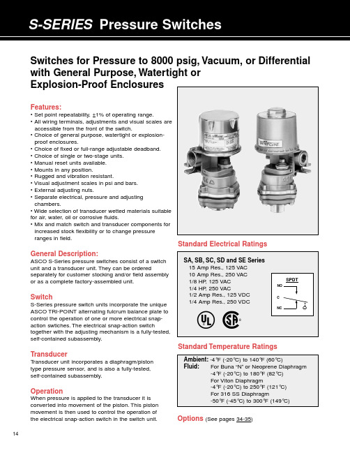
14Features:• Set point repeatability, +1% of operating range.• All wiring terminals, adjustments and visual scales are accessible from the front of the switch.• Choice of general purpose, watertight or explosion-proof enclosures.• Choice of fixed or full-range adjustable deadband.• Choice of single or two-stage units.• Manual reset units available.• Mounts in any position.• Rugged and vibration resistant.• Visual adjustment scales in psi and bars.• External adjusting nuts.• Separate electrical, pressure and adjusting chambers.• Wide selection of transducer wetted materials suitable for air, water, oil or corrosive fluids.• Mix and match switch and transducer components for increased stock flexibility or to change pressure ranges in field.General Description:ASCO S-Series pressure switches consist of a switch unit and a transducer unit.They can be orderedseparately for customer stocking and/or field assembly or as a complete factory-assembled unit.SwitchS-Series pressure switch units incorporate the unique ASCO TRI-POINT alternating fulcrum balance plate to control the operation of one or more electrical snap-action swtiches.The electrical snap-action switchtogether with the adjusting mechanism is a fully-tested,self-contained subassembly.TransducerT ransducer unit incorporates a diaphragm/piston type pressure sensor, and is also a fully-tested, self-contained subassembly.OperationWhen pressure is applied to the transducer it is converted into movement of the piston.This pistonmovement is then used to control the operation of the electrical snap-action switch in the switch unit.Standard Electrical RatingsSwitches for Pressure to 8000 psig, Vacuum, or Differential with General Purpose, Watertight or Explosion-Proof EnclosuresStandard Temperature RatingsOptions (See pages 34-35)EnclosuresASCO TRI-POINT S-Series switches are available in three standard enclosures.All of these enclosed units are made in accordance with NEMA and UL standards. General Purpose–Type 1.These enclosures are designed for indoor use to protect personnel from accidental contact with the equipment.S-Series general purpose switch units consist of a copper-free* aluminum die-cast body with a formed copper-free* aluminum cover;two 3/4”conduit hubs with one plug are provided.Watertight–T ype 4.Watertight and dust-tight enclo-sures are intended for use indoors and outdoors to protect the enclosed equipment against splashing or falling water, windblown dust and water, hose directed water, and severe external condensation.S-Series watertight switch units have a copper-free* aluminum die-cast body and a formed copper-free* aluminum cover with Buna “N”gaskets;two 3/4”conduit hubs with one plug are provided.Explosion-Proof–T ypes 7 and 9.T ype 7 enclosures are intended for use in locations defined by the National Electrical Code as Class I.T ype 9 enclosures are intended for Class II locations.Class I locations are those in which flammable gases are or may be present in the air in sufficient quantities to produce explosive or ignitable mixtures.Class I loca-tions are classified by group letter, which defines partic-ular atmospheres.Division 1 locations are areas where the hazardous concentration exists continuously, inter-mittently or periodically under normal operating condi-tions.Division 2 locations are those where the haz-ardous vapors are present only in case of accidental rupture or breakdown of equipment.ASCO TRI-POINT explosion-proof enclosures with letter B, C or D in the fifth position are listed for Class I, Groups B, C, and D, Division 1.They are also suitable for the less stringent Division 2 environment.Class II locations are those which are hazardous because of the presence of combustible dust.All ASCO TRI-POINT explosion-proof enclosures are listed for Groups E, F, and G locations.The switch body and cover are die-cast copper-free* aluminum with a Buna “N”gasket.T wo 3/4”conduit hubs with one plug are provided.Dimensions (inches)* Less than 0.6% copper.1518the maximum1934H-Series, P-Series and S-Series Snap-Action Switch OptionsOptional snap-action switches to meet specific electrical loads or application conditions are available on most ASCO TRI-POINT switch units. Generally, the construction of a switch unit with optional snap-action switches contains other specific parts and may be ordered only as a factory-built unit. To specify a particular optional construction, add the appropriate suffix to the switch unit action switch (suffix “P ”P-SeriesSwitch OptionsPanel Mount –Open frame P-Series compact switch units areavailable for panel mounting with the switch unit inside and the transducer outside. The panel separates the fluid sensing portion from the electromechanical portion. Five holes for bolts and operating stem must be drilled or punched through the panel.Three constructions are available: add the suffix listed below to the switch unit catalog number for the desired thickness.S-SeriesSwitch OptionsIndustrial Adjusting Nut Covers –Available in clear plastic or metal to prevent tampering with set point adjusting nuts.Clear plastic cover:To order, add suffix “1” to the switch unit catalog number, or order separately as SP01.Metal cover:To order, add suffix “2” to the switch unit catalog number, or order separately as SP02.JIC Construction –A switch unit having the electrical and adjusting nut covers attached to the switch body by a chain. Also designed to Type 13specifications. To order, add suffix “3”to the switch unit catalog number, or order separately as SP03.Terminal Block –Applicable to switch units with one single-poledouble-throw switch. The terminal strip is prewired to the snap-action switch. To order, add suffix “4” to the switch unit catalog number, or order separately as SP04.Factory Sealed –Explosion-proof units may be ordered with a factory seal separating the electrical chamber from the conduit hubs and 24” long #14 AWG 105°C. rated lead wires. To order, change the fourth digit of the “3”35Pressure Transducer OptionsP-Series and S-Series Temperature Transducer OptionsSpecial Wetted Materials –The following diaphragms maybe substituted on transducer body materials of aluminum,brass, polyester and stainless steel. To order, substitute the Oxygen Cleaning –Pressure transducers for oxygen serviceshould be specially cleaned. They are degreased and blacklight inspected, then assembled in a clean area and tested with oil-free air or nitrogen. Use metal body transducer with viton or neoprene diaphragm and add suffix “H ”Pressure Snubbers –A pressure snubber (1/4” NPTF by1/4” NPTM) installed in the transducer pressure connection will dampen the pressure spikes to a value which will not cause damage. It consists of a body with a porous metal disc of stainless steel through which the fluid passes. To order,select a snubber compatible with the fluid. Available by seperate catalog number only (see table below).Process Connection –A female process connection (1/4”NPT) is standard on all pressure transducers. A 1/2” NPT is available as an option on gauge pressure transducers. To order, add suffix “B ”Note: Armored Capillaries –Double braided copper armor isstandard for copper capillary units. Stainless steel spiral interlocked armor is available for stainless steel capillary units. Add suffix “C ” to transducer catalog number.Thermal Well –Use with direct or remote sensors forprotecting sensing bulb. This allows removal of bulb while maintaining a pressure-tight vessel. Available in 1/2” NPT or 3/4”NPT process connection in brass or 316 SS. Dimensions are in accordance with SAMA Std. RC17-9. Standard “U ” dimension (insertion length) is 2-1/2” for direct mount and 6’capillary units and is 4-1/2” for 12’capillary units.Longer Capillaries –Standard copper and stainless steelcapillary units can be furnished in 12’lengths. To order, add suffix “D ” to transducer catalog number. Consult ASCO for longer length capillaries.Union Connector –For use with remote units for mountingof bulb in fluid being controlled. Available in 1/2” NPT and 3/4” NPT process connections in brass or 316 SS.Thermal WellJam nuts provided with thermal wells.11Switch Unit – ASCO uses the term “switch unit ” to describe the electromechanical portion of a pressure or temperature switch. This is used in conjunction with a transducer unit to form a complete pressure or temperature switch.Transducer Unit – ASCO uses the term “transducer unit ” to describe that portion of a pressure or temperature switch to which a pressure or temperature is applied which converts the input signal to another form of energy to operate the switch unit.Two-Stage (Dual)– ASCO uses the term “two stage ” todescribe a pressure or temperature switch which is equivalent to two pressure or temperature switches which are independently adjustable. This switch is equivalent to two fixed deadband switches.Deadbands – The deadband is the difference between the set point and reset point readings. Deadbands are listed in the specification tables at nominal values. They are representative of the deadbands of the units at the middle of the range.The deadband values for the full range adjustable deadband switches and limited adjustable deadband switches indicate the values through which the deadband may be adjusted.Generally, as the set point is adjusted through the operating range, the deadband will vary. Normally, it will becomenarrower as the set point is towards the bottom of the range,and will become wider when the set point is towards the top of the range. The graph shown below indicates representative trends of this type of deadband variation.Temperature switch deadbands are a result of the characteris-tics of the vapor pressure curve as well as other factors.Normally, this results in a deadband which is narrower in the top third of the range than in the bottom third of the range.The values published are nominal and representative of mid-range set points.36Accuracy – The maximum deviation from the set point under specified operating condition (ambient temperature,barometric pressure, etc.).Adjustable Deadband – Refers to the capability of apressure or temperature switch to allow the deadband to be adjusted over a given range. Certain ASCO TRI-POINT switches have an adjustable deadband which can be adjusted over the total operating range of the switch.Adjustable Operating Range – The pressure or tempera-ture range of the switch within which the set point may be adjusted.Differential Pressure – The difference between twopressures. A differential pressure switch senses two pressure sources and can be adjusted to actuate on a desired difference between them.Guage Pressure – The actual reading of a typical pressure guage and is the difference between the pressure within a vessel and the atmospheric pressure surrounding it. It is normally measured in pounds per square inch (psig).Manual Reset – The switch is a semi-automatic device which operates automatically with a signal change in one direction but must be manually reset once the signal returns to its original position.Proof Pressure – A pressure which a device can besubjected to for extended periods of time without changes in its operating characteristics.Rated Overrange Temperature – A temperature which a device can be subjected to for extended periods of time without changes in its operating characteristics.Repeatability – The closeness of agreement among a number of consecutive measurements of the output for the same value of input under the same operating conditions approaching from the same direction. Repeatability isnormally specified as a percentage of the upper limit of the operating range.Example: Operating range 5-100 psig with +1%repeatability; equals +1% of 100 psig or +1 psig.Reset Point – After a pressure or temperature switch has reached its set point and operated the electrical switch, it must return to a point called the reset point before the electrical switch can return to its original position.Set Point – The pressure reading at which the electrical switch element changes contact position (it can be specified either increasing or decreasing).DefinitionsDeadbands1.5 x Catalog Value Catalog Value Half Catalog ValueBottom Mid TopPosition of Set Point in Range37These recommendations are to be used as a guide only, as service life of material is dependent on temperature, concentrations, or catalysts that may be added and other conditions which are beyond our control.Consult ASCO for specific service applications.Note:Items in black circles are standard catalog units.All others available on factory order.P - Indicates preferred construction. S - Indicates satisfactory construction.Transducer Material Code of Two Digits represents process connection material and diaphragm material, respectively; these are the sixth and seventh positions of the pressure transducer catalog number.Process Connection: 6th Position Diaphragm: 7th Position 1 Aluminum 4 316 S.S. 1 Buna “N ” 4 316 S.S.2 Brass 7 Nylon/Brass2 Viton6 Ethylene Propylene 3 303 S.S.3 Neoprene7 FluorosiliconeFluid Compatibility GuideFor high purity applications use stainless steel transducers.Notes:1Oxygen service requires special cleaning, specify suffix “H ”.2For steam service a condensate loop (pigtail) is required.3For pressure transducers for combustion service see pages 20-23.4Material availability refers to standard gauge pressure constructions only.5。
瑞尔科技 'SS-H' 压力开关产品说明书
“SS-H”PRESSURE SWITCH OPERATION MANUAL (4HL2/4HH2) 3/01 1.0 INTRODUCTIONThe Ruelco “SS-H” hydraulic pressure switch is a two way bleed valve which is operated by pressure acting on a piston opposing an adjustable spring force. It functions as either a normally closed or normally open valve. Pressure applied to the sense port will cause the valve to operate.The Model 4HH2 operates as a normally open valve and is called a high switch. If sense pressure acting on the piston is at normal levels, it is insufficient to overcome the spring force. The middle o-ring on the spool is positioned below the bent grooves on the bottom sleeve, thus preventing the instrument pressure from passing to the “Vent” port of the switch body. When the pressure acting on the piston becomes large enough to overcome the spring force, the spool shifts and the center o-ring moves in between the vent grooves on the bottom sleeve. Instrument pressure at the “In” port “Bleeds” into the reservoir through the “Vent” port.The pressure switch “Bleed” action is the same for Model 4HL2. For this model of operation, the switch acts as a normally closed valve and is called a low switch. When normal sense pressure is acting on the piston, the center o-ring on the spool is above the vent grooves in the top sleeve, thus preventing the instrument pressure from passing to the “Vent” port of the switch body. When the sense pressure decreases to an abnormal level, the spring force shifts the spool and the middle o-ring on the spool becomes positioned in between the vent grooves in the top sleeve. Instrument pressure at the “In” port, “Bleeds” into the reservoir through the ‘Vent” port. Changing the sense pressure value when the switch is used as either a high or low id done by altering the force of the spring, the size of the sense piston force is accomplished by turning the spring cap to increase or decrease the spring compression. The piston diameter is changed by adding or removing o-rings on the piston or changing the piston.2.0 INSTALLATIONThe “SS-H” can be panel mounted (with optional panel mount nut) or supported by piping from the sense port in either verticalor horizontal positions. If the switch is mounted horizontally, it is recommended that the small vent holes in the side of the switch body be oriented in a downward position. This will prevent any debris from accumulating in the spring cavity or above the sense piston.Proper PIPE thread sealant should be used on any pipe fittings threaded into the pressure switch ports. If stainless steel fittings are used, a sealant that will prevent galling is required. When the switch is mounted using the ½” NPT base connectionis adequately tightened, DO NOT loosen the body from the base or re-position the ports. Instead, remove the switch and re-make the ½” NPT connection.3.0 DISASSEMBLY (See Spec Sheet)Tools and materials required for proper disassembly, repair and assembly are as follows:1. 7/8”, 1” and 1-5/16” open endwrenches or two crescent wrenchesof adequate size.2. Smallpliers.3. For switches using ¼” diameterpiston, 1 ¼” open end wrench or asuitable crescent wrench.4. High quality silicone base lubricant.5. An appropriate safety solvent.3.1 PARTIALDISASSEMBLYA) SpringRemoval3.1.1 If the switch is installed in anoperating instrument system, it is notnecessary to remove any instrumentsupply or sense pressure. If the unitis a high switch, it will trip whenchanging the spring. If it is a lowswitch, it will not trip when changingthe spring. Precautions should betaken to avoid any unwantedreactions in the instrumentationsystem.3.1.2 To obtain access to the spring (Item2), rotate the lock ring (Item 4)clockwise to loosen it from the springcap (Item 1).3.1.3 Rotate the spring cap (Item 1)counterclockwise until it isdisengaged from the switch body(Item 10).3.1.4 Remove the spring from its cavity inthe switch body. If the parts tube(Item 3) is inside the spring, careshould be taken not to lose it.3.1.5 Follow the procedures in repair andassembly section (Steps 4.15 and4.16) of this manual re re-install thespring.B) PistonRemoval3.1.6 If the switch is panel mounted, it isnot necessary to remove it from thepanel. It will be necessary todisconnect any piping or tubing fromthe base that would prevent thebase from being removed. When theswitch is supported by the ½” NPTconnection on its base (Item 16),disconnect any piping or tubing fromthe switch body that would preventits removal from the switch base.CAUTION: Be sure that allinstrument or sense pressures arecompletely bled to zero beforedisconnecting any piping or tubing.3.1.7 Use the appropriate wrenches tohold and loosen the base from theswitch body. Unthread the basecompletely from the switch body.3.1.8 Use the small pliers and grip theraised ridge on top of the piston(Item 15) and pull it from the switchbase (Item 16).3.1.9 If the ¼” diameter piston (Item 19) isinstalled and must be removed fromthe large piston, use the properwrench to hold the ¼” diameterpiston and grip the large piston withthe pliers at the small diameterabove the groove for the .5” pistono-ring (Item 18). Rotate either onecounterclockwise to loosen andseparate the pistons.3.1.10 Remove the installed o-ring from thepiston.3.1.11 Procedures for re-installing thepiston o-rings are in the repair andassembly procedure of this manual.3.2 FULLDISASSEMBLYNOTE: Use the following instructions to completely disassemble the pilot for repair and cleaning. CAUTION: Be sure that all instrument or sense pressures are completely bled to zero before disconnecting any ping or tubing.3.2.1 Follow the procedures stated underpartial disassembly to remove thespring and pistons.3.2.2 Remove the spool (Item 14) from theswitch body. If it is necessary, usethe small pliers and grip the smallend of the spool. Removing thespool also removes the bottomsleeve (Item 13).3.2.3 To remove the top sleeve (Item 8),an o-ring pick (pointed prying tool)can prove useful. Just insert the pickinto one of the .041 holes in the topsleeve and pull the sleeve out. Notethat while using the pick, care shouldbe taken not to scratch the bore onthe top sleeve.3.2.4 The seals on the shaft and sleevesmay now be replaced as perinstructions given in the repair andassembly section of this manual.。
【推荐】使用开关说明书-推荐word版 (12页)
本文部分内容来自网络整理,本司不为其真实性负责,如有异议或侵权请及时联系,本司将立即删除!== 本文为word格式,下载后可方便编辑和修改! ==使用开关说明书篇一:压力开关操作说明书CN CN目录1 说明 1.1 重要说明 1.2 开关标识 2 探测头安装 2.1 压力与真空探测头2.2 差压探测头 2.3 温度探测头3 封装外壳的安装 3.1 “C”型外壳 3.2 “Z”型外壳 3.3 “V”型和“W”型外壳3.4 “M”型外壳 4 电气安装5 设定点调节6欧共体标准符合说明1 说明1.1 重要说明 * * * * * * * * * * * * *BETA压力开关属于精密仪器请正确放置或搬动。
BETA压力开关在达到设定点的(差压)压力或者温度时开关动作。
在按照说明书指示正确安装,该开关的设计与结构是完全免维护的。
切莫采用液态油或油脂润滑开关的任何部件。
除了更换外壳密封与安装支架外,不要移动或更换本开关的任何部件。
避免暴露在超高温、超低温、有侵蚀性环境中,-30~80℃为适宜温度。
调节螺丝有自锁性,所以在调节设定点后禁止封死调节螺丝。
安装前请详细检查铭牌上数据。
所有尺寸均以mm毫米标注。
如果您需要帮助请与供应商联系,开关只有在去污清洗后才能进行维护检修。
如果您需要额外的膜片O形圈和微动开关,请给出序列号向供应商购买。
开关的检修维护请由专业的仪表工程师实施。
除了更换膜片O形圈和微动开关以外,其它形式的检修维护有厂方执行。
非厂方检修维护的操作会影响产品本身的质量保证。
本章节的指导说明书的步骤也是安装步骤说明。
地基与工程环境的强烈振动可能会影响开关的正常功能。
1.2 开关标识压力开关的铭牌上面标明了规格型号,4到7步可以确定该压力开关的设计组成,后缀的X+数字来表明特殊要求,该特殊要求可参照数据书。
外壳封装C1-P304L-S1N-B1-K1-Y-X2第一个字符即第一步标明了外壳封装形式:C、V、W、Z或M,参照图1-4和15。
SS-1 压力开关产品说明书

Phone (504) 340-0055Fax(504) 340-0056SS-1 Pressure SwitchModel 4102Model 4102ItemQty.Qty DescriptionMaterial1Spring Spring Ca p 316L or ASTM-A-351 S.S.2A 1Spring (Blue)ASTM-4012B —Spring (Red)ASTM-4012C —Spring (Silver)ASTM-4012D —Spring (Gr een) optional Inconel X-7502E —Spring (Y ellow) ello (Y optional Inconel X-7502F —Spring (Purple) optional Inconel X-750Body For SS-1CF-8M St.Stl.Parts T ube T Acetate Butyrate Lock Ring AISI 316 St.Stl.Panel Mnt.Ring (Optional)AISI 316 St.Stl.Spring Plate AISI 316 St.Stl.8*4Spool O-ring Viton Spool For SS-117-4 PH St.Stl.10*2Shuttle Seal Viton 111Shuttle AISI 316 St.Stl.12*1Spool O-ring Viton 13*2Spool Sleeve Seal Viton 141Spool Spool Sleeve AISI 316 St.Stl.151 1.25”/.50” Piston AISI 316 St.Stl.16*1 1.25” Piston O-ring Viton 171 1.25”/.50”/.25” Base AISI 316 St.Stl.18*1.50” Piston O-ring Viton 191.25” Piston (Optional)AISI 316 St.Stl.20*1.25” Piston Backup eflon eflo T 21*1.25” Piston O-ring Viton 22—Repair Kit * Items Parts T ube ube T Not Supplied With Switches Using 3.0” or .187” Sensor Base.Parts List For Pressure Switch Model SS-11314151617191Repair GENERAL DESCRIPTION: The Ruelco ‘SS-1’ pneumatic pressure switch is a three way block and bleed valve that is operated by pressure acting on a piston opposing an adjustable spring force. It functions as either a normally closed or normally open valve, depending on through which of the two ports the instrument pressure is supplied. These ports are marked as ‘HI IN’ or ‘LO IN’ on the switch body. The output port, marked ‘OUT’ on the switch body, is the same for either mode of operation. Pressure applied to the sense port will cause the valve to operate. The Ruelco ‘SS-1’ pneumatic pressure switch can also be used as a two way bleed only valve in which case one of the ‘HI IN’ or ‘LO IN’ ports is plugged depending on whether the valve is to be used as a high or a low pilot.SS-1Pneumatic Pressure SwitchFEATURES• 316 stainless steel construction (models to N.A.C.E. MR0175 available).• Standard base range 10-10,000 p.s.i. (with 1/4" piston option).• Operating pressure range from .5 to 20,000 psi.• Block-and-bleed 3-way valve.• Holds constant and accurate set points.• Designed for 1% plus or minus repeatability on set points.• Minimum deadband between trip and reset pressure.• Spring may be replaced with instrument and sensing pressure present inthe sensor.• Vent above sensing piston prevents high pressure from entering instru-ment supply should a piston seal leak develop.• Optional tamper proof lock-out device available upon request.Valv V e T ypeT 3 or 2 Way Way Wa Set Point Deviation+1%Deadband 3 Way Way Wa 3% of Range 2 Way y Way Wa 5% of Range Range Max.Instr.Instr Press. 3 Way Way Wa 60 PSI 2 Wa y WayWa 150 PSI Cv Factor Factor Factor 0.160Ambient T emp em T .-20 to 250 deg.F Range -29 to 122 deg.CSwitch SpecificationsSensor T ype T PistonMax.P Oper.Oper ress.10,000 PSI (690 BAR)Burst Pressure 20,000 PSI (1380 BAR)emperatur em T e -20 to 250 Deg.F Range-29 to 122 Deg.C.25”/.50”/.25” 1.25”/.50”/.25” Switch Sensor Specifications * For Switch and 1.25/.50/.25 Sensor Base.A 2.12 (53.8)B (Max) 6.13 (155.7)C 1.32 (33.5)D 1.43 (36.3)E 1.22 (31.0)F 1.82 (46.2)G 1.23 (31.2)H 2.0 (50.8)(50.8)I 1/2” MNPT J1/4” MNPT Panel Mount Hole 1.875 (48.0)Valv V e Ports 1/4” FNPT Weight*Weig W 4.9 lbs.(2.3Kg)Dimensions Inch (MM)ITEM .QTY DESCRIPTION TERIAL TE M A 231Upper Housing 17-4 P .H.P St.Stl.241Piston Assembly17-4 P .H.P St.Stl.251SealViton 26Lower Housing 17-4 P .H.P St.Stl.27—Rep.Kit F/ 3.0” BaseItems 8,10,12,13,253.0" Sensor Base1LWhile this information is presented in good faith and believed to be accurate, Ruelco, Inc. does not guarantee satisfactory results from reliance upon such information. Nothing contained herein is to be construedas a warranty or guarantee, expressed or implied, regarding the performance, merchantability, and fitness with respect to the products. Ruelco, Inc. reserves the right, without notice, to alter or improve the designs or specifications of the products described herein.Ordering Code:4102 X X X X X X X X X 0 X 0 0 0 0BASE MODEL NUMBER Standard Corrosive Service - (-)N.A.C.E.Option - NSPRING CODE (see range chart)PISTON STON PIST CODE (see range chart)ITEM TY .QTY DESCRIPTION TERIAL TE M A 281Retainer Sleeve AISI 316 St.Stl.291.187” Sensor Base 17-4 P .H.P St.Stl.301.187” Piston 17-4 P .H.P St.Stl.311Back -Up RingGlass Filled T efloneflo T 321SealViton3319/16” Gland Nut AISI 316 St.Stl.3419/16” Gland Collar AISI 316 St.Stl.35—Rep.Kit F/ .187” BaseItems 8,10,12,13,31,32.187" Sensor BaseK 2.0 IN.(50.8 MM)L 3.75 IN.(95.2 MM)M 1/2” FNPT Weight*Weig W 8.5 lbs.(3.7 Kg.)* For Switch and 3.0” Sensor BaseSensor T ype T PistonMax.P Oper.Oper ress.20,000 PSI (1380 BAR)Burst Pressure 40,000 PSI (2760 BAR)emperatur em T e -20 to 250 Deg.F Range-29 to 122 Deg.C Sensor T ype T PistonMax.P Oper.Oper ress.5,000 PSI (345 BAR)Burst Pressure 10,000 PSI (690 BAR)emperatur em T e -20 to 250 Deg.F Range-29 to 122 Deg.C N 2.0 IN.(50.8 MM)P 2.57 IN.(65.3 MM)Q 9/16/ M/P Autoclave Weight*Weig W 5.0 lbs.(2.3 Kg.)* For Switch and .187” Sensor BaseSpring Codes (COLOR)ST AN DARD INCONEL SPRING SPRING B (Blue)G (Green)R (Red)Y (Y ello (Y w)S (Silver)P (Purple)Piston Diameter Piston CodeAvailab Avai A le Ranges - PSI (BAR)XXXXXXXXXXXXXXX3.0" 3.0" 3.0" 1.25"1.25"1.25".50".50".50".25".25".25".187".187".187"24.5-20(.03-1.4)4-40(.3-2.75)10-80(.7-5.5)10-115(.7-7.9)20-230(1.4 - 15.8)50-450(3.4 -31)200-750(13.8-51.8)500-1500(34.5-103.5)1000-3000(69-207)1000-3000(69-207)2000-5000(138-345)5000-10000(345-689)2000-5000(138-345)3500-9000(241-620)8500-20000(586-1380)1112233344OPTIONAL BASEOPTIONAL PISTONOPTIONAL BASESS SeriesPressure Switches SS-1 High Flow SS-2 Standard SS-2 High Flow(Pneumatic or Hydraulic)SS-1 Differential SS-2 Differential SS-4 Hydraulic BleedSS-E Electric SS-E Electric DifferentialSS-1 With Optional ScaleModel 4103SS-1 With Optional Scale Model 4103。
Ceraphant 压力开关说明书
压力开关,用于表压和绝压监测,确保安全测量应用Ceraphant 压力开关用于气体、蒸汽、液体和粉尘的压力报警,绝压或表压。
Ceraphant 通过多项认证,配备多种过程连接,使用广泛。
优势•高重复性和高长期稳定性•最高参考测量精度:0.3%•用户自定义量程–最高量程比:5:1–传感器的最大测量范围400 bar (6 000 psi)•316L 材质的外壳和过程膜片操作和电气连接符合VDMA 24574-1:2008标准Products Solutions Services技术资料Ceraphant PTC31B, PTP31B过程压力测量TI01130P/00/ZH/04.1771363974Ceraphant PTC31B, PTP31B2Endress+Hauser目录文档信息 (4)文档功能...................................4信息图标...................................4文档资料...................................4术语和缩写.................................6量程比计算.................................6功能与系统设计 (8)测量原理:过程压力测量........................8测量系统...................................8仪表特点...................................9产品设计..................................10系统集成. (10)输入 (11)测量变量..................................11测量范围 (11)输出....................................13输出信号..................................13调节范围..................................13开关容量..................................134...20 mA 信号范围...........................13负载(适用于模拟量输出型仪表)................134...20 mA 报警信号...........................13死区时间和时间常数..........................14动态响应..................................14开关量输出的动态响应........................14阻尼时间..................................14电源....................................15接线端子分配...............................15供电电压..................................16电流消耗和报警信号..........................16电源故障..................................16电气连接..................................16电缆规格..................................16残余波动电压...............................16供电电压的影响.............................16过电压保护 ................................16陶瓷膜片的性能参数 (17)参考操作条件...............................17测量绝压小量程的测量不确定性..................17安装位置的影响.............................17分辨率...................................17参考测量精度...............................17零点输出和满量程输出的热变化..................17长期稳定性................................17启动时间..................................17金属膜片的性能参数 (18)参考操作条件...............................18测量绝压小量程的测量不确定性..................18安装位置的影响.............................18分辨率...................................18参考测量精度...............................18零点输出和满量程输出的热变化 ..................18长期稳定性 ................................18启动时间. (18)安装....................................19安装条件..................................19安装位置的影响.............................19安装位置..................................19氧气应用安装指南...........................21环境条件 (22)环境温度范围...............................22储存温度范围...............................22气候等级..................................22防护等级..................................22抗振性...................................22电磁兼容性(EMC)............................22过程条件 (23)带陶瓷膜片的仪表的过程温度范围................23带金属膜片的仪表的过程温度范围 ................23压力标准. (23)机械结构 (24)设计及外形尺寸.............................24电气连接..................................24外壳.....................................25内置陶瓷膜片的过程连接.......................26内置陶瓷膜片的过程连接.......................27内置陶瓷膜片的过程连接.......................28内置陶瓷膜片的过程连接.......................28内置金属膜片的过程连接.......................29内置金属膜片的过程连接.......................30内置金属膜片的过程连接.......................31内置金属膜片的过程连接.......................31带齐平安装的金属膜片的过程连接................32接液部件材料...............................33不接液部分材质.............................34清洁.....................................34可操作性 (36)通过现场显示操作...........................36开关量输出功能.. (37)证书和认证 (39)CE 认证...................................39RoHS 认证.................................39RCM-Tick 认证..............................39压力设备指令2014/68/EU(PED)...............39其他标准和准则.............................39CRN 认证..................................40标定选项..................................40标定.....................................40检测证书..................................40订购信息 (41)供货清单 (41)Ceraphant PTC31B, PTP31B附件 (42)焊座 (42)M12插头 (42)文档资料 (43)应用文档 (43)技术资料 (43)操作手册 (43)简明操作指南 (43)Endress+Hauser3Ceraphant PTC31B, PTP31B4Endress+Hauser文档信息文档功能文档包含仪表的所有技术参数、附件和可以随仪表一起订购的其他产品的简要说明。
数字式压力开关 ZSE20C(F) ISE20C(H) 使用说明书

文件No.PS※※-OMU0008CN-D数字式压力开关ZSE20C(F)ISE20C(H)安全注意事项 2型式表示・型号体系 9产品各部分名称及功能 11用语说明 12安装·设置 16设置方法 16配管方法 19配线方法 21设定概要[测试模式] 24压力的设定 25 3步设定模式 26简单设定模式 28功能选择模式 30功能选择模式 30出厂时的设定 30 F0 单位切换功能 32 F1 OUT1的设定 33 F2 OUT2的设定 36 F3 数字滤波器的设定 38 F4 自动预设功能的设定 39 F5 FUNC端子的设定 41 F6 显示值微调的设定 43 F10 子画面的设定 44 F11 显示分辨率的设定 50 F80 省电模式的设定 51 F81 密码输入的设定 52 F82 线名输入的设定 54 F90 全功能的设定 55 F96 输入信号确认 57 F97 复制功能的选择 58 F98 输出确认 60 F99 恢复出厂设置 62其他设定 63维护 67忘记密码的场合 67故障一览表 68规格 77规格表 77外形尺寸图 79安全注意事项此处所示的注意事项是为了确保您能安全正确地使用本产品,预先防止对您和他人造成危害和伤害而制定的。
这些注意事项,按照危害和损伤的大小及紧急程度分为“注意”“警告”“危险”三个等级。
无论哪个等级都是与安全相关的重要内容,所以除了遵守国际标准(ISO/IEC)、日本工业标准(JIS)*1) 以及其他安全法规*2)外,这些内容也请务必遵守。
*1) ISO 4414: Pneumatic fluid power -- General rules relating to systemsISO 4413: Hydraulic fluid power -- General rules relating to systemsIEC 60204-1: Safety of machinery -- Electrical equipment of machines (Part 1: General requirements)ISO 10218: Manipulating industrial robots-SafetyJIS B 8370: 空气压系统通则JIS B 8361: 油压系统通则JIS B 9960-1: 机械类的安全性‐机械的电气装置(第1部: 一般要求事项)JIS B 8433: 产业用操作机器人-安全性等*2) 劳动安全卫生法 等安全注意事项本产品适用于下述“保证以及免责事项”、“适合用途的条件”。
霍尼韦尔C6097A,B压力开关说明书

PRODUCT DATA65-0237-1CP-UM-5109E® U.S. Registered TrademarkCopyright © 2000 Honeywell Inc. • All Rights ReservedC6097A,BPressure SwitchesAPPLICATIONThe C6097 Pressure Switches are safety devices used in positive-pressure or differential-pressure systems to sense gas or air pressure changes.FEATURES•For use with natural gas, liquid propane (LP) gas, or air.•Diaphragm-actuated safety-limit switch.•Switch can be wired to turn on alarm.•C6097A models break control circuit at setpoint on pressure fall.•C6097B models break control circuit at setpoint on pressure rise.•Lockout with manual reset and recycle options.•Lockout models have external manual reset button.•Removable transparent cover protects scaleplate and adjusting knob.•Pipe tappings allow selection of positive pressure, differential pressure (air only) or venting connections (NPT mount only).•1/4 in. NPT or flange mount models for direct mounting to Honeywell Integrated Valve Train.•Optional switch position indicator lamp available.•IP54 enclosure standard.•Ranges: 0.4 to 5 in. wc, 3 to 21 in. wc, 12 to 60 in. wc or 1.5 to 7 psi.•Surge orifice.ContentsApplication ........................................................................1Features ...........................................................................1Specifications ...................................................................2Ordering Information ........................................................2Installation ........................................................................4Wiring ...............................................................................5Settings and Adjustments .................................................5Operation and Checkout ..................................................6C6097A,B PRESSURE SWITCHES65-0237—12ORDERING INFORMATIONWhen purchasing replacement and modernization products from your TRADELINE® wholesaler or distributor, refer to theTRADELINE® Catalog or price sheets for complete ordering number.If you have additional questions, need further information, or would like to comment on our products or services, please write or phone:1.Your local Home and Building Control Sales Office (check white pages of your phone directory).2.Home and Building Control Customer Logistics Honeywell Inc., 1885 Douglas Drive NorthMinneapolis, Minnesota 55422-4386 (612) 951-1000In Canada—Honeywell Limited/Honeywell Limitée, 155 Gordon Baker Road, North York, Ontario M2H 3N7.International Sales and Service Offices in all principal cities of the world. Manufacturing in Australia, Canada, Finland, France, Germany, Japan, Mexico, Netherlands, Spain, Taiwan, United Kingdom, U.S.A.SPECIFICATIONSModels:C6097A Pressure Switch: Breaks a circuit when pressure falls to scale setting. See Table 1.C6097B Pressure Switch: Breaks a circuit when pressure rises to scale setting. See Table 1.Table 2 shows switch ratings and Table 3 shows alternate electrical ratings when used with Honeywell Flame Safeguard Programmers.Minimum Ambient Temperature: -40°F (-40°C).Maximum Ambient Temperature: 140°F (60°C).Connections (Depending on Model):1/4-18 NPT tapping for main or high-pressure connection.1/8-27 NPT tapping for vent or low-pressure connection (air only).Flange mount for connection to Honeywell Integrated Valve Train (internal vent only, no external connections).Scale Range:0.4 to 5 in. wc (0.10 kPa to 1.25 kPa).3 to 21 in. wc (0.75 to 5.23 kPa).12 to 60 in. wc (3.0 kPa to 15 kPa).1.5 to 7 psi (10.3 kPa to 48 kPa).Approvals:Underwriters Laboratories Inc. listed.Canadian Standards Association listed.Factory Mutual: Approved.Industrial Risk Insurers: Acceptable.CSD-1 AFB: Acceptable.Accessories:32003041-001 C6097 Cover for manual reset models.32003040-001 C6097 Cover for recycle models.32003039-001 Position Indication Lamp Kit.Dimensions: See Fig. 1 and 2.Fig. 1. C6097 1/4 in. NPT Mount dimensions in in. (mm).C6097A,B PRESSURE SWITCHES365-0237—1a Acceptable media: Natural gas, liquid propane (LP) gas, and air .Table 1. Pressure Switch Model Selection.Model Operating Pressure Range Manual Reset DifferentialNon-Manual ResetDifferentialDifferential Type Maximum Rated Pressure(continuous) (psi)Manual Reset Media a Switch Action at Setpoint Comments Maximumat Minimum Setpoint Maximumat MaximumSetpoint Nominal Maximum C6097A10040.4 to 5 in. wc——0.16 in. wc 0.24 in. wc Additive2.9 No Air/Gas Breaks N.O. to C.connection on pressure fall.1/4 in. NPT Mount C6097A1012 3 to 21 in. wc2.4 in. wc 4.2 in. wc —— 4.3Yes Air/Gas 1/4 in. NPT Mount C6097A1020 3 to 21 in. wc 2.4 in. wc 4.2 in. wc —— 4.3Yes Air/Gas Flange Mount C6097A103812 to 60 in. wc 10 in. wc 12 in. wc —— 4.8Yes Air/Gas 1/4 in. NPT Mount C6097A104612 to 60 in. wc10 in. wc12 in. wc—— 4.8Yes Air/Gas Flange Mount C6097A1053 3 to 21 in. wc—0.24 in. wc0.48 in. wc 4.3No Air/Gas 1/4 in. NPT Mount C6097A1061 3 to 21 in. wc ——0.24 in. wc0.48 in. wc4.3No Air/Gas Flange Mount C6097A107912 to 60 in. wc —— 1.1 in. wc 2.4 in. wc 4.8No Air/Gas 1/4 in. NPT Mount C6097A108712 to 60 in. wc—— 1.1 in. wc 2.4 in. wc 4.8No Air/Gas Flange Mount C6097A10950.4 to 5 in. wc 0.6 in. wc 1.0 in. wc —— 2.9Yes Air/Gas 1/4 in. NPT Mount C6097A1103 1.5 to 7 psi 1.1 psi 1.4 psi ——9.3Yes Air/Gas Flange Mount C6097A1111 1.5 to 7 psi 1.1 psi 1.4 psi ——9.3Yes Air/Gas 14 in. NPT Mount C6097A1129 1.5 to 7 psi ——0.1 psi 0.39.3No Air/Gas Flange Mount C6097A1137 1.5 to 7 psi——0.1 psi 0.39.3No Air/Gas 1/4 in. NPT Mount C6097A12100.4 to 5 in. wc——0.16 in. wc 0.24 in. wc 2.9No Air/Gas Flange Mount C6097A12280.4 to 5 in. wc ———— 2.9Yes Air/Gas Flange MountC6097B100212 to 60 in. wc 10 in. wc 12 in. wc ——Subtractive4.8Yes Air/Gas Breaks N.C. to C. connectionon pressure rise.1/4 in. NPT Mount C6097B101012 to 60 in. wc10 in. wc12 in. wc —— 4.8Yes Air/Gas Flange Mount C6097B1028 3 to 21 in. wc2.4 in. wc 4.2 in. wc —— 4.3Yes Air/Gas 1/4 in. NPT MountC6097B1036 3 to 21 in. wc 2.4 in. wc 4.2 in. wc —— 4.3Yes Air/Gas Flange Mount C6097B1044 1.5 to 7 psi 1.1 psi 1.4 psi ——21.0Yes Air/Gas Flange Mount C6097B1051 1.5 to 7 psi1.1 psi1.4 psi ——21.0Yes Air/Gas 1/4 in. NPT Mount C6097B1069 3 to 21 in. wc ——0.24 in. wc0.48 in. wc4.3No Air/Gas Flange Mount C6097B107712 to 60 in. wc —— 1.1 in. wc 2.4 in. wc 4.8No Air/Gas Flange Mount C6097B108512 to 60 in. wc —— 1.1 in. wc 2.4 in. wc 4.8No Air/Gas 1/4 in. NPT Mount C6097B1093 1.5 to 7 psi ——0.1 psi 0.3 psi 21.0No Air/Gas Flange Mount C6097B1101 1.5 to 7 psi——0.1 psi 0.3 psi 21.0No Air/Gas 1/4 in. NPT Mount C6097B11193 to 21 in. wc——0.24 in. wc0.48 in. wc4.3NoAir/Gas1/4 in. NPT MountC6097A,B PRESSURE SWITCHES65-0237—14Table 2. Switch Ratings (Amperes)Table 3. Alternate Electrical Ratings when used withHoneywell Flame Safeguard Programmers.Fig. 2. C6097 Flange Mount dimensions in in. (mm).INSTALLATIONWARNINGExplosion or Fire Hazard.Can cause severe personal injury, death or property damage.Observe all safety requirements each time a control is installed on a burner.When Installing this Product...1.Read these instructions carefully. Failure to follow them can damage the product or cause a hazardous condition.2.Check the ratings given in the instructions and on the product to make sure that the product is suitable for your application.3.Installer must be a trained, experienced service technician.4.After installation is completed, check out product operation as provided in these instructions.WARNINGElectrical Shock Hazard.Can cause serious personal injury or death.Disconnect power supply before beginning installation. More than one disconnection can be involved.MountingNOTE:On flange models, remove the label holding theO-ring in place and make sure O-ring seal is in place before mounting the pressure switch on the valve.The C6097 models allow NPT or flange (directly to valve) mounting. The NPT models have a hexagonal fitting with a 1/4 in. NPT tapping, which is the high pressure connection, in differential applications. The bleed fitting is 1/8 in. NPTtapped. In differential pressure control applications using air only, connect the lower pressure to the bleed fitting. See Fig. 1 and Table 1. In applications using combustible gases, vent the bleed tapping according to applicable standard code or jurisdictional authority.C6097 models with flange mount can be fitted directly toHoneywell Integrated Valve Train (model specific). See Fig. 2 and Table 1. The flange mount models vent internally, with no external tap.Mount the C6097A,B in any position.Leak CheckAfter installation, perform a leak check on the pressure switch:1.Turn on main gas. Make sure gas has reached thepressure switch (e.g., high gas pressure switch)2.Check installation for gas leaks using a gas leak detector or a soap solution.120/240 Vac, 50/60 HzInductive Full Load 3.0Locked Rotor18.0Resistive5.0DeviceRatingIgnition Transformer 540 VA Pilot Valve 50 VAMain Valve400 VA with 2-1/2 times inrush.C6097A,B PRESSURE SWITCHES565-0237—1WIRINGWARNINGElectrical Shock Hazard.Can cause serious personal injury or death.Disconnect power supply before beginning installation. More than one disconnection can be involved.Make sure that all wiring agrees with all applicable localcodes, ordinances and regulations. An opening is provided to accommodate rigid conduit or armored cable for line voltage operation (see Fig. 3 and 4). Do not overload the switch contacts (see Switch Ratings in the Specifications section). The switching schematic is shown in Fig. 5.Fig. 3. C6097 (manual reset switch model)with cover removed.Fig. 4. C6097 (recycle model) with cover removed.SETTINGS AND ADJUSTMENTSPressure Setpoint Adjustmentdial (Fig. 3, 4 and 5) clockwiseto decrease the pressure setting.Fig. 5. C6097 schematic.C6097A,B PRESSURE SWITCHES65-0237—16OPERATION AND CHECKOUTOperationThe manual reset C6097A diaphragm actuates the snap-acting switch to break a control circuit and lock out when pressure falls to the scale setting. The recycle C6097Amodels recycle automatically when the control circuit returns to scale setting plus differential.The manual reset C6097B diaphragm actuates the snap-acting switch that breaks a control circuit and locks out when the pressure rises to the scale setting. The recycle C6097B models recycle automatically when the control pressure falls to the scale setting minus differential.Manual ResettingThe C6097A manual reset models lock out when pressure falls to the scale setting and require manual resetting after the pressure rises to scale setting plus differential to resume normal operation.The C6097B manual reset models lock out when pressure rises to the scale setting and require manual resetting after the pressure falls to scale setting minus the differential to resume normal operation.To reset, once normal operating pressure is restored, push the reset button in as far as it goes, then release.IMPORTANTLockout models cannot be made to recycleautomatically by permanently holding in the reset lever.CheckoutC6097 Gas Fuel Application1.Set cutoff pressure.2.Open main supply line. Depress reset lever on lockout models until switch makes control circuit.3.Set controller and limit switch to call for heat.4.For C6097A: Close the manual gas shutoff valve. C6097 should open control circuit when pressure reaches cutoff point.For C6097B: Open the manual gas shutoff valve, wait a few minutes for the pressure to rise; then lower the scale setting until the switch breaks control circuit and locks out.5.For C6097A: Open the shutoff valve, return thepressure switch to its original setting and press the reset button (if necessary).For C6097B: raise setting to normal and press reset button (if necessary).6.Allow system to operate through at least one complete cycle to make sure all components are functioning properly.C6097A Air Application1.Set cutoff pressure.2.Turn on fan.3.Block fan inlet or filter area. Switch should break control circuit when pressure drops to cutoff point. Manual reset models lock out.4.Remove obstruction. Press reset lever (manual reset models) and allow system to operate through at least one complete cycle to be sure all components are functioning properly.765-0237—165-0237—1 G.R. Rev. 4-00Home and Building Control Home and Building ControlHoneywell Asia Pacific Inc.Honeywell Inc.Honeywell Limited-Honeywell Limitée Room 3213-3225Honeywell Plaza 155 Gordon Baker Road Sun Hung Kai Centre P.O. Box 524North York, Ontario No. 30 Harbour Road Minneapolis, MN 55408-0524M2H 3N7Wanchai Hong KongHoneywell Latin American Region Honeywell Europe S.A.480 Sawgrass Corporate Parkway 3 Avenue du Bourget Suite 2001140 Brussels Sunrise FL 33325Belgium。
双设定压力开关中文说明书

注意:超程距离已在出厂前预先设定,也就是说,为了达到最佳的性能,开关元件组合已精确地在外壳内定 位。通常在现场不必再行调节。如果有必要进行调节,则必须严格地遵循制造厂批准的步骤。任何在现场随
便的移动或更换可能会降低性能、使担保作废并可能使该装置失效。
校准
a. 拆除外壳的盖子。 b. 若要提高1号(左侧)开关元件起动时的设定值,则用3/4英寸开口扳手以顺时针方向转动六角调节螺母。 c. 调节时越过调节螺母的顶部观察外壳内壁上的校准刻度,即可达到近似的设定值。可用一1/4% 的外接压力
其压力传感元件是一对力平衡式、活塞驱动的组合 件,通过弹性膜片和静态密封O形环予以密封。此结 构中唯有压力接口、两套膜片和O形环传感组合件是 接触介质的部件。
重要:务必拧紧和固定该工艺接头,使压力开关上所 承受的任何弯曲和扭曲力量均减小到最低限度。切勿 将压力接口从本体上松开, 因为这可能会造成泄漏或
安装
185.7 * 7.31
70.4 * 2.77
高低压双点系列压力开关可用适当的螺栓固定在隔 墙、仪表盘或管架支柱上。当在不规则或不平整表面 上安装压力开关时,先要在外壳和安装面之间的螺栓 上套上橡胶垫圈。
单位= mm
in.
注意:若不在外壳和安装面之间放置橡胶垫圈,就可 能在外壳上产生扭力,从而导致开关的假动作,或使 该开关失效。
不推荐采用光依靠工艺接口或电气接口的安装方式。
*
251.2 9.89
9.7 .38
直径为9/32 的固定孔
57.2 (通常2个)
114.3 2.25 4.50
工艺接头
V1 全天候密封型
138.9 5.47 69.6
2.74
电气接头
3/4 NPT(F) (制造厂密封
PSW-190系列钢管压力开关产品说明书

Repeatability: PSW-191, 192, 195 and 196: ±1% PSW-193, 194, 197 and 198: ±1.5%
Shock: Setpoint repeats after 50 g 10 ms duration
1/2 NPT Conduit
1/4 NPT High Press 1/8 NPT Low Press
32 (1.26)
SPECIFICATIONS
Switch: SPDT, 5 A at 250 Vac or 30 Vdc gold-clad silver contacts for loads down to 5 mA at 6 Vdc, 2 mA at 12 Vdc and 1 mA at 24 Vdc
Pressure Connection: PSW-191, 192, 195 and 196: 1⁄8 NPT PSW-193, 194, 197 and 198: 1⁄4 NPT
Weight: 128 g (4.5 oz)
500 (20) Pigtail Leads
WIRE CODE BLUE = N.O. BLACK = N.C. VIOLET = COM.
H-18
Vibration: Setpoint repeats after 10 g, 5 to 500 cps
Enclosure and Cover: Aluminum with irridite finish rated for 100 hr salt spray; potted and gasketed for outdoor use
压力开关说明书

压力开关说明书产品作用:压力开关用于测量流经管道的液体(水及氟化处理的制冷剂)或空气的压力状态,其典型应用是显示压力与控制压力。
●机械寿命≥10万次(参考值JC系列≥40万次)●设定值调整:当设定值精度要求不高时,可根据控制器标度尺和系统中的压力表进行调试,当设定值要求较高时,请用专用压力校验仪和精密压力表进行调试。
压力开关内部安装有一个高灵敏度的单刀双掷接近开关。
开关可设定二个切换值,通常称为上限切换值和下限切换值。
具体调试方法:1. 压力开关顶部的右侧调节螺丝是直接调节上限切换值;2. 压力开关顶部的左侧调节螺丝是调节开关压差;3. 它们的关系是:上限切换值-开关压差=下限切换值即:上限切换值可以直接在标尺上调节下限切换值要通过1~3操作来调节*例如:(高压保护器的用法)要求被控介质的压力保持在0.5~0.8Mpa之间。
1. 选用设定值范围在0.1~1.0Mpa的压力控制器(JC-210,HNS-210)2. 旋动顶部右边的压力调节螺丝,使指针指示在标度尺的0.8Mpa(8kg或8bar)处,此值为上限切换值。
3. 旋动顶部左边的压力调节螺丝,使指针指示在标度尺的0.3Mpa,下限切换值=上限切换值-开关压差=0.8-0.3=0.5,此值为下限切换值。
4. 将控制器的接线端子接入被控的电气回路。
请注意:①为公共接线。
③为常开端输出。
⑤为常闭端输出。
高压保护,请连接①⑤,在正常升压时,①-⑤接通(①-③不通)。
压力升到设定上限时即0.8Mpa处,①-⑤不通(①-③接通)。
压力下降时,此时①-③接通,压力下降到下限设定点即0.3Mpa处时。
又切换为①-⑤接通(①-③不通)。
降压停止,压力回升,则自动循环。
5. 接通电源,让被控介质(水、气)压力上升。
请注意观察调正,使压力开关的设定值与压力表指示一致,(如压力升至上限设定时,开关尚未动作,即旋动压力调节螺丝,微调到切换动作,并再次重复验证一次)并作下限验证,过程同上。
sciphar压力开关说明书
sciphar压力开关说明书Sciphar压力开关说明书一、产品介绍Sciphar压力开关是一种用于控制和调节压力的设备,可广泛应用于工业生产中的液体、气体和蒸汽管路系统中。
它能够根据管路中的压力变化,自动开关和关闭电路,从而实现对压力的监测和控制。
二、产品特点1. 高精度:Sciphar压力开关具有高精度的测量能力,能够准确地检测管路中的压力变化,并根据设定值进行开关操作。
2. 可调性:该压力开关具有可调节的压力范围,用户可以根据实际需求,通过调节开关上的旋钮,灵活地设置开关的工作压力。
3. 稳定性:Sciphar压力开关采用高品质材料制造,具有良好的耐压性和稳定性,能够在恶劣的工作环境下长期稳定运行。
4. 可靠性:该产品经过严格的质量控制和测试,具有良好的可靠性和耐久性,能够在长时间的使用中保持良好的性能。
5. 安全性:Sciphar压力开关具有过载保护功能,当管路中的压力超过设定值时,开关会自动断开电路,起到保护设备和管路的作用。
三、使用方法1. 安装:首先,将Sciphar压力开关正确安装在管路中,并确保连接紧固可靠;其次,根据实际需要调节开关上的旋钮,设置合适的工作压力。
2. 调试:打开控制电源,观察开关的状态以及管路中的压力变化。
当管路中的压力达到设定值时,开关会自动切换状态,从而开启或关闭相应的电路。
3. 维护:定期检查Sciphar压力开关的工作状态,如发现异常或损坏,应及时更换或维修。
另外,保持管路的清洁和正常运行,避免杂质和污垢对开关的影响。
四、应用范围Sciphar压力开关广泛应用于各类液体、气体和蒸汽管路系统中,例如工业生产中的压力控制和调节,以及水泵、风机、空调等设备的保护和控制。
五、注意事项1. 在安装和调试过程中,应确保工作环境安全,避免电气和机械伤害。
2. 在使用Sciphar压力开关之前,应仔细阅读产品说明书,并按照要求进行正确操作。
3. 禁止随意更改开关上的参数和设定值,以免影响设备和管路的正常运行。
压力开关使用说明书

压力开关使用说明书
压力开关是一种用于控制压力电路的装置。
它可以根据预设的压力值,监测压力的变化,并在达到设定值时切断或接通电路。
以下是压力开关的使用说明书:
1. 安装:请先确保断电,并将压力开关正确安装到压力管道上。
注意接口的紧固度和密封性,以确保压力传递和测量的准确性和可靠性。
2. 调整设定压力:使用调整螺钉,可以更改压力开关的设定值。
顺时针旋转调整螺钉将增加设定压力,逆时针旋转将降低设定压力。
在调整时应小心,并根据需要进行适当的测试和验证。
3. 连接电路:根据需要,将压力开关与控制电路连接。
确保正确连接电源和负载,以确保开关的正常工作和可靠性。
4. 运行监测:在正确连接电路后,可以应用压力到系统中,并观察开关的动作。
当压力超过设定值时,开关会切断电路或接通电路。
根据需要,可以通过相应的指示灯或报警装置进行监测和反馈。
5. 维护:定期检查和维护压力开关是必要的。
请检查接口的紧固度、密封性和电路连接是否正常。
清洁压力开关并确保其正常运行。
6. 安全注意事项:在操作和维护过程中,请务必注意个人安全。
请遵循相关的安全操作规程,并根据需要使用适当的个人防护装备。
《压力开关说明》.(DOC)

操作手册压力继电器(压力开关)YSJ-340系列一、概述YSJ-340系列压力继电器是一种超小型压力控制仪表,用于液压、气动系统的压力显示与控制,可替代德国贺德克HYDAC(贺德克)EDS300系列压力继电器。
该仪表采用了高精度压力传感器,电路部分以高性能单片机微处理器为核心,具有3位LED数字显示及轻触开关输入的人机界面、具有开关量(报警)输出及4~20mA模拟输出,是在机械继电器无法胜任的条件(如压力剧烈波动、强环境振动、高精度高速度控制、小体积等)下可靠工作的理想选择。
二、性能指标◇测量范围:0~1.6—0~60MPa◇电源电压:16~36VDC◇输出信号:(RL≤250Ω)◇接口螺纹:G1/4◇环境条件:环境温度:-20℃~60℃介质温度::-20℃~80℃存储温度:-40℃~125℃相对湿度:0~80%耐冲击:≤50g/ms耐振动:≤10g/(0~500HZ)◇输出信号精度:1.0◇过载压力:1.5%倍满量程压力◇最大功耗:≤3W触点容量:24VDC/1.2A(MAX)三、功能根据不同型号,装置可提供下列功能◇三位显示当前压力(正常工作)◇按压力、预设开关点输出开关量◇输出模拟量◇基本设定菜单◇提供四种不同输出模式:◇YSJ341带1路开关量输出(负载最大电流1.2A,无模拟量输出)◇YSJ342带2路开关量输出(负载最大电流1.2A,无模拟量输出)◇YSJ343带1路开关量输出(负载最大电流1.2A)和1路模拟量输出(4~20mA)◇YSJ344带2路开关量输出(负载最大电流1.2A)和1路模拟量输出(4~20mA)四、安装YSJ340可以通过压力管接头(DIN3852内螺纹G1/4),直接装在液压集成快上。
电气连接必须由国家认定合格的电工操作(参考中国电工国家标准规范)。
压力继电器的外壳必须同时良好的接地。
如安装在液压块里,块体通过液压系统接地时有保证的。
若用微型软管安装,客体必须单独接地。
Oildyne 压力开关产品说明说明书
OildynePressure SwitchesFor AC Power3.4-345 bar (50-5000 psi) RangeTypical ApplicationsPressure switches sense when a pre-selected fluid pressure is reached or lost and make or break an electrical circuit. Their operation can stop or start a machine’s cycle, actuate indicator lights or sequential operations. Properly installed, their operation is auto-matic and limited by your imagination and need.• Spring rangeDuplex models contain two separate switches which can be activated by one or two sensing ports depend-ing on the subplate configuration. See dimensional data for options.• environmentally resistantEnvironmentally resistant models are available on spe-cial order for certain hazardous location service.SubplatesSubplates are available for in-line mounting of Oildyne pressure switches. This allows further flexibility in mounting to existing equipment. Ports in 1/8 NPT or 7/16-20 (SAE-4) straight thread are standard. The duplex switch has two types of subplates, one with a port for each side of the switch, the other with one port only, for both sides of the switch.Pressure Switch Features• VersatileOur designs allow the switches to be used in any mounting orientation. They can sense hydraulic fluid pressure or air/gas pressure. A simple spring change allows the same basic switch to be used through a wide range of pressure settings.• durableHeavy-duty electrical contacts are rated for 15 amps at 125, 250 or 460 VAC. Normally open and normally closed contacts are provided.• reliableRepeatability is accomplished through a combination of a PTFE seal and a hardened, nickel-plated steel piston. This use of low-friction materials and the de-sign of the unique PTFE seal (or diaphragm*) prevents the piston from sticking. Repeatability, sensitivity and reliability are excellent. Limited piston movement pre-vents inertial forces from damaging the piston stop.*Used for lower pressure differential applications.Single Switchduplex Switchtriplex SwitchPRESSURE SETTING EASYMAKES CHANGINGADJUSTING SCREW LEAK PROOF OPERATION O-RING SEAL FOR1/2" PIPE CONDUIT CONNECTIONALL ALUMINUM CONSTRUCTIONELECTRICAL CONNECTIONSFOR ACCESS TOEASILY REMOVED COVER AND NORMALLY CLOSED CONTACTSSWITCH WITH NORMALLY OPEN HEAVY DUTY ELECTRICALAND ZERO LEAKAGE MINIMUM FRICTION PTFE SEALS FOR SPRINGDRAIN LINES NEEDEDSEALED PISTON, NO DISC OR DIAPHRAGMSINTERED METAL STAINLESS STEEL construction44Catalog HY22-1121/USfeatures and applications Pressure SwitchesParker Hannifin Corporation Oildyne DivisionMinneapolis, MN 55428 USA45DimensionsSingle Pressure SwitchSubplates (Single & duplex)Catalog HY22-1121/USdimensions Pressure SwitchesParker Hannifin Corporation Oildyne DivisionMinneapolis, MN 55428 USA46DifferentialThis is the pressure required to open and close theswitch contacts. It is a constant value dependent on the characteristics of the switch. The differential will be in the range as shown on the above table. For minimum differential, select the lightest spring including the maxi-mum setting desired.Spring Selection GuideSingle SwitchPK-01B Subplate (1/8” Pipe)PK-50B Subplate (SAE-4 Str. Thd.)duplex SwitchPK-01C Subplate (1/8” Pipe) Two PortsPK-50C Subplate (SAE-4 Str. Thd.)Two Ports PK-01D Subplate (1/8” Pipe) One Port PK-50D Subplate (SAE-4 Str. Thd.)One Porttriplex Specify Subplate PK-50H (SAE-4Str. Thd.) and Three Single SwitchSpecifications from Chart at Left.Standard Product Ordering CodeCatalog HY22-1121/UStechnical Information Pressure Switchesnote: 100 psi = 6.9 bar.Parker Hannifin Corporation Oildyne DivisionMinneapolis, MN 55428 USASpring numberSpring range adjustment range repeatability Plus or Minusdifferential range Spring color 150 - 100 psi 50 to 100 psi 2 psi 50 to 90 psi Green 2100 - 300 psi 75 to 300 psi 4 psi 50 to 100 psi Black 3300 - 500 psi 150 to 500 psi 5 psi 50 to 125 psi Red 4500 - 1000 psi 200 to 1000 psi 8 psi 50 to 150 psi Blue 51000 - 2000 psi 300 to 2000 psi 15 psi 75 to 250 psi White 62000 - 3000 psi 400 to 3000 psi 20 psi 75 to 250 psi Yellow 73000 - 4000 psi 500 to 4000 psi 25 psi 125 to 350 psi Orange 84000 - 5000 psi500 to 5000 psi50 psi150 to 450 psiPink。
安全压力开关说明书

221 Code Process R ange & Temp.(6) Vac 0-600 1000 2000- Material Limits in.H 2O psi psi 3000 °F psi B-Buna N 0 to 150 ● ● ● ● V-Viton 20 to 300 ● ● ● T-Teflon 0 to 150 ● ● ● ● S-SS (5)(10) 0 to 300 ● ● P -Monel (5)(10) 0 to 300 ● ● NOTES: 1. Standard switch. 2. D ual switches are 2 SPDT snap-action switches not independently adjustable. 3. Estimated dc rating, 2.5A, 28 Vdc (not UL listed). 4. Estimated dc rating, .4A, 120 Vdc (not UL listed). 5. Available on pressure only. 6. A mbient operating temperature limits –20 to 150°F , all styles. Setpoint shift of ±1% of range per 50°F is normal. Switch calibrated at 70°F reference. 7. Items are wetted by process fluid. 8. Refer to Option Table. 9. O rder Option XUD, stainless steel process connection.10. On differential switches, stainless steel is available in 15, 30, 60 and 90 psid ranges only. Includes Teflon O-ring and 316 SS connection. TO ORDER THIS B-SERIES PRESSURE SWITCH:Pressure and Differential Pressure Switches, Watertight Enclosure, Type 400, B-Series • C hoice of actuators, including designs for fire-safe and NACE applications (8)• Readily available • Standard pressure connection materials: Pressure psi ranges - 316L stainless steel Differential psid ranges- Nickel-plated brass (9) of water ranges - Epoxy coated carbon steel B4 - P ressure switch, type 400, watertightenclosure meets NEMA 3, 4, 4X and 13, IP66 requirementsD4 - D ifferential pressure switch, type 400,watertight enclosure meets NEMA 3, 4, 4X and 13, IP66 requirementsThis general purpose Ashcroft ® switch series is ideal for use in virtually all Industrial and OEM applications.• Watertight NEMA 4X enclosure, IP66• Choice of switch elements for all applications, including hermeti-cally sealed• Wide choice of wetted materials, including all-welded Monel or stainless steel• Fixed or limited adjustable deadband• Approved for UL, CSA and FM (8) ratings • Setpoints adjustable from 15-100% of range4 - OPTIONS (See pages 238-239)5 - STANDARD PRESSURE RANGES (See page 235) 3 - ACTUATOR SEAL (7) Order D escription/Maximum Electrical Ratings Code UL/CSA Listed SPDT 20(4) Narrow deadband 15A, 125/250 Vac 21(9) Ammonia service 5A, 125/250 VacHermetically sealed22(3) switch, narrow 5A, 125/250 Vac deadband 23 Heavy duty ac 20A,125/250 Vac15A,125/250/480 Vac 24(1)General purpose 1/2A, 125 Vdc 1/4A, 250 Vdc 25 Heavy duty dc 10A,125/ Vac or dc 1/8HP 125/ Vac or dc 26(4)Sealed environment 15A, 125/250 Vac proof 27 High temp. 300°F 15A, 125/250 Vac 28Manual reset trip 15A, 125/250 Vac on increasing 29 Manual reset trip 15A, 125/250 Vac on decreasing 31 Low level (gold) 1A,125/250 Vac contactsHermetically sealed32 switch, general 11A, 125/250 Vac purpose 5A, 30 Vdc50 Variable deadband 15A,125/250 Vac UL/CSA Listed Dual SPDT (2)We recommend hermetically sealed switch elements for improved reliability. The hermetically sealed switch provides uncompromising contact protection in harsh or corrosive environments. The Ashcroft 400 Series is also approved for installation in Division II hazardous areas when supplied with hermetically sealed contacts.L-recognized component, LOOK FOR THIS AGENCY MARK ON OUR PRODUCTS。
Oildyne 压力开关说明书
OildynePressure SwitchesFor AC Power3.4-345 bar (50-5000 psi) Range43Typical ApplicationsPressure switches sense when a pre-selected fluid pressure is reached or lost and make or break an electrical circuit. Their operation can stop or start a machine’s cycle, actuate indicator lights or sequential operations. Properly installed, their operation is auto-matic and limited by your imagination and need.• Spring rangeDuplex models contain two separate switches which can be activated by one or two sensing ports depend-ing on the subplate configuration. See dimensional data for options.• environmentally resistantEnvironmentally resistant models are available on spe-cial order for certain hazardous location service.SubplatesSubplates are available for in-line mounting of Oildyne pressure switches. This allows further flexibility in mounting to existing equipment. Ports in 1/8 NPT or 7/16-20 (SAE-4) straight thread are standard. The duplex switch has two types of subplates, one with a port for each side of the switch, the other with one port only, for both sides of the switch.Pressure Switch Features• VersatileOur designs allow the switches to be used in any mounting orientation. They can sense hydraulic fluid pressure or air/gas pressure. A simple spring change allows the same basic switch to be used through a wide range of pressure settings.• durableHeavy-duty electrical contacts are rated for 15 amps at 125, 250 or 460 VAC. Normally open and normally closed contacts are provided.• reliableRepeatability is accomplished through a combination of a PTFE seal and a hardened, nickel-plated steel piston. This use of low-friction materials and the de-sign of the unique PTFE seal (or diaphragm*) prevents the piston from sticking. Repeatability, sensitivity and reliability are excellent. Limited piston movement pre-vents inertial forces from damaging the piston stop.*Used for lower pressure differential applications.Single Switchduplex Switchtriplex SwitchPRESSURE SETTING EASYMAKES CHANGINGADJUSTING SCREW LEAK PROOF OPERATION O-RING SEAL FOR1/2" PIPE CONDUIT CONNECTIONALL ALUMINUM CONSTRUCTIONELECTRICAL CONNECTIONSFOR ACCESS TOEASILY REMOVED COVER AND NORMALLY CLOSED CONTACTSSWITCH WITH NORMALLY OPEN HEAVY DUTY ELECTRICALAND ZERO LEAKAGE MINIMUM FRICTION PTFE SEALS FOR SPRINGDRAIN LINES NEEDEDSEALED PISTON, NO DISC OR DIAPHRAGMSINTERED METAL STAINLESS STEEL construction44Catalog HY22-1121/USfeatures and applications Pressure SwitchesParker Hannifin Corporation Oildyne DivisionMinneapolis, MN 55428 USA45DimensionsSingle Pressure SwitchSubplates (Single & duplex)Catalog HY22-1121/USdimensions Pressure SwitchesParker Hannifin Corporation Oildyne DivisionMinneapolis, MN 55428 USA46DifferentialThis is the pressure required to open and close theswitch contacts. It is a constant value dependent on the characteristics of the switch. The differential will be in the range as shown on the above table. For minimum differential, select the lightest spring including the maxi-mum setting desired.Spring Selection GuideSingle SwitchPK-01B Subplate (1/8” Pipe)PK-50B Subplate (SAE-4 Str. Thd.)duplex SwitchPK-01C Subplate (1/8” Pipe) Two PortsPK-50C Subplate (SAE-4 Str. Thd.)Two Ports PK-01D Subplate (1/8” Pipe) One Port PK-50D Subplate (SAE-4 Str. Thd.)One Porttriplex Specify Subplate PK-50H (SAE-4Str. Thd.) and Three Single SwitchSpecifications from Chart at Left.Standard Product Ordering CodeCatalog HY22-1121/UStechnical Information Pressure Switchesnote: 100 psi = 6.9 bar.Parker Hannifin Corporation Oildyne DivisionMinneapolis, MN 55428 USASpring numberSpring range adjustment range repeatability Plus or Minusdifferential range Spring color 150 - 100 psi 50 to 100 psi 2 psi 50 to 90 psi Green 2100 - 300 psi 75 to 300 psi 4 psi 50 to 100 psi Black 3300 - 500 psi 150 to 500 psi 5 psi 50 to 125 psi Red 4500 - 1000 psi 200 to 1000 psi 8 psi 50 to 150 psi Blue 51000 - 2000 psi 300 to 2000 psi 15 psi 75 to 250 psi White 62000 - 3000 psi 400 to 3000 psi 20 psi 75 to 250 psi Yellow 73000 - 4000 psi 500 to 4000 psi 25 psi 125 to 350 psi Orange 84000 - 5000 psi500 to 5000 psi50 psi150 to 450 psiPink。
- 1、下载文档前请自行甄别文档内容的完整性,平台不提供额外的编辑、内容补充、找答案等附加服务。
- 2、"仅部分预览"的文档,不可在线预览部分如存在完整性等问题,可反馈申请退款(可完整预览的文档不适用该条件!)。
- 3、如文档侵犯您的权益,请联系客服反馈,我们会尽快为您处理(人工客服工作时间:9:00-18:30)。
DG型气体压力开关使用说明书●请阅读和保持一个安全的地方解释符号●, 1, 2, 3 ... = 功能➔ = 用法说明所有工作必须在阅读操作说明后才能进行!警告!不正确的安装、调整、修改、操作或维护可能导致伤害或物质损失。
使用前先阅读说明书。
这个单位必须安装依照本条例的实施。
标准声明We, the manufacturer, hereby declare that the products DG.., marked with product ID No. CE 0085AP0467, comply with the essential requirements of the following Directives:– 90/396/EEC in conjunction with EN 1854,– 73/23/EEC in conjunction with the relevant standards.The relevant products correspond to the type tested by the notified body 0085. Comprehensive quality assurance is guaranteed by a certified Quality System pursuant to DIN EN ISO 9001 according to annex II, para-graph 3 of Directive 90/396/EEC.Elster Kromschröder GmbH, Osnabrück测试➔电源电压、环境温度和外壳——看类型的标签。
➔最大介质温度:-15 + 80°C。
在系统暴露于更高的热应力、热设备上时压力开关必须安装在上游。
DG..B型➔正压时1号位置为进气DG..U型, DG..H型, DG..N型➔正压时1号或者2号位置为进气,气体为空气、天然气或者烟气(其他位置密封),通风时气体从3号或者4号位置离开。
➔负压时3号或者4号位置为进气,气体为空气、天然气或者烟气(其他位置密封),通风时气体从1号或者2号位置离开。
➔对于压差时,用1号或2号和3号或4号,气体为空气、天然气或者烟气,其他位置密封。
➔在连接3号和4号位置时使用过滤垫,防止气体中的杂质弄脏电触点。
➔ DG..B, DG..U switch with rising pressure.➔ DG..H switches and locks off with rising pressure – with manual reset.➔ DG..N switches and locks off with falling pressure – with manual reset.➔ Fit an upstream restrictor if the system is subject to greatly fl uctuating pressures (see acces-sories).➔ The service life will be shorter if subject to ozone concentrations exceeding 200 µg/m3.Installation➔Fitting position as required, pref-erably with diaphragm vertical, with unobstructed view of the adjustment dial. Ensure that no dirt or moisture can penetrate open ventilation ports.➔ The housing may not contact masonry. Minimum clearance 20 mm.➔ Avoid subjecting the DG to strong or violent vibrations.➔ Condensation must not be allowed to get into the housing. At subzero temperatures malfunctions/failures due to icing can occur.➔ When using silicone tubes, only use silicone tubes which have been sufficiently cured.➔ Continuous operation at high temperatures accelerates the ageing of elastomer materials.➔ Protect from direct sunlight (even with IP 65).DG..B..S➔ Do not connect gas but only O2 or NH3 to the positive pressure port 1.Ensure that no grease is used during installation.DG1 Flush the pipework.2 Use suitable sealing material.3 If dirt can accumulate at port3 or 4, use the fi lter, Order No. 74916199.4 Fit the DG.Tightness testAdjusting the switching pressure ps1Disconnect the system from the electrical power supply.WiringDG➔ 24–250 V AC:I = 0.05–5 A, cos ϕ = 1,I = 0.05–1 A, cos ϕ = 0.6; DG..G➔ 12–250 V AC:I = 0.01–5 A, cos ϕ = 1,I = 0.01–1 A, cos ϕ = 0.6;12–48 V DC:I = 0.1–1 A.➔ If the DG..G has switched a voltage > 24 V and a current > 0.1 A once, the gold plating on the contacts will have been burnt through. It can then only be operated at this power rating or higher power rating.➔ Contacts 3 and 2 close when subject to increasing pressure. Contacts 1 and 3 close when subject to falling pressure.1Disconnect the system from the electrical power supply.2 3 4567 8 92 3 4567 8 9Function check➔ We recommend a function check once a year. AccessoriesFastening setConnecting set➔ For monitoring the minimum/maximum inlet pressure pe.External adjustmentPIA test keyRestrictor orificeTube set➔ for air onlyStandard coupler plugPilot lamp red or greenfor 110/120 V AC or 220/250 V ACLED red/green for 24 V DC/ACGas pressure switchDG..T, DG..HT, DG..NTfor natural gas, clean cokeoven gas, LPG, biologicallyproduced methane and airOperating instructionsInstallingwiringadjustingby authorized trained personnel only!WARNING! Improper installation, adjustment, modification, operation or maintenance could lead to injury or damage. Alladjustments must be made by a qualifiedtechnician.Wiring must comply with local codes and theNational Electrical Codes. To prevent thepossibility of property damage turn off electrical power, depressurize installation, ventfluid to a safe area before servicing.DG..T, DG..HT, DG.. NT for➔excess pressure, connection 1 or 4,➔negative pressure, connection 2,➔differential pressure, connection 1 or 4 and 2pmax to atmosphere or max. differential pressure between upper and lower chamber: 8.5 psi (600 mbar)Ambient and gas temperature:-40 to +140 °F (-40 to +60 °C)(DG..S: +5 to +140 °F (-15 to +60 °C))At an ambient temperature resp. gas temperature below -22 °F (-30 °C) the adjustedswitch point may change perceptibly.➔The service life will be shorter if subject to ozone concentrations exceeding 200 µg/m3.Accessories see back page.Installing pressure switch into the pipework➔Mounting position arbitrary, but preferably with horizontal or vertical diaphragm –with clear view to graduated ring –please make sure that dirt or humidity does not get into the connections open for aeration –➔the housing must not touch its surrounding walls – minimum distance 1" (25 mm) –➔avoid subjecting the gas pressure switch to strong or violent vibrations.➔When using silicone tubes, only use silicone tubes which have been sufficiently after baked.➔Protect gas pressure switch from direct sunlight.➔If dirt can accumulate at connection 4, use the filter, Order No. 74916199.● Use suitable jointing compound.Excess pressure testType of gas: gas, air, fumes● Connect excess pressure to connection 1 or 4, 1/4 NPT –➔max. +8.5 psig (+600 mbar) –➔connection 2 must stay open.Negative pressure test Type of gas: air, fumes● Connect negative pressure to connection 2, 1/8 NPT, flat gasket –➔max. -8.5 psig (-600 mbar) –➔connection 1 or 4 must stay open –➔connection 2 joins the upper chamber with the microswitch, therefore, do not connect to gas carrying pipes! Differential pressure test Type of gas: air, fumes ● Connect the higher pressure to 1 or 4, 1/4 NPT –● connect the lower pressure to 2, 1/8 NPT –➔connection 2 joins the upper chamber with the microswitch, therefore, do not connect gas carrying pipes!Check for soundness when testing the system as a whole –● test pressure: 1.5 times the operating pressure – max. 29 psig (2 bar) for a period of less than 15 minutes,● use detergent at pipe connections.Wiring of pressure switchWARNING! Ensure that there is no voltage in the supply line when you make terminal connections.● Unscrew cover.● Remove cover plate.● Pass wires through 1/2 NPT conduit and connect – terminals 2 x AWG 18 (2 x 1.5 mm2).➔Ensure good ground connection via terminal .➔Microswitch:NO 2 –COM 3 closes on pressure increase NC 1 –COM 3 opens on pressure increaseElectrical DataSwitching capacity: for voltages 30 –240 V AC use pressure switch with silver-plated plated contacts (standard version);I = 5 A resistive, I = 0.5 A with cos ϕ = 0.6.Contact rating: 6 A, For small voltages < 30 V AC or DC use special version with gold-plated contacts –DG..TG –I = 0.1 resistive, I = 0.05 A with cos ϕ = 0.6.Short-circuit proof: quick-action fuse up to 8 A acc. to UL 198 GType of enclosure: NEMA 3 (IP 54) 1/2 NPT conduit connection Connection: screw terminals 2 x AWG 18 (2 x 1.5 mm2)Adjusting pressure switch to the required switching pressureThe set switching pressure is obtained: with ambient temperature 32 °F to 140 °F (0 °C to60 °C) with increasing pressure➔with vertical diaphragm: accurately,➔with horizontal diaphragm: the switching pressure is approx. 0.08 " W.C. (0.2 mbar) higher than the reading➔with suspended diaphragm: the switching pressure is approx. 0.08 " W.C. (0.2 mbar) less than the reading. The readings are approximations. Adjustment – example DG 50 T3 = pressure test point The setting of 6 " W.C. (15 mbar) applies for➔excess pressure of +6 " W.C (+15 mbar),➔negative pressure of -6 " W.C. (-15 mbar) or➔differential pressure of 6 " W.C. (15 mbar) (+10 " W.C. (+25 mbar) at connection1 or 4, +4 " W.C. (+10 mbar) at connection 2) Setting of switching pressure:● turn required value on the scale disk over the pointer.Checking of set switching pressure● Measure exact switching point: using a manometer at test point 3 for excess pressure and by metering the voltage at NC 1 or NO 2● if necessary, re-adjust scale disk the readings are approximations!● Put cover plate on and press firmly, put cover back on and screw tight – first the two screws beside the scale disk.Gas pressure switches DG..T require little servicing.➔Conduct a function check once a year, or every six months for biologically produced methane.Accessories for DG..TCover with external adjustmentFit nipple with external hexagon into hexagon socket on the graduated disk. Screw on cover with seal and gland.Control lamp green220 V AC/240 V AC110 V AC/120 V AC (standard)48 V AC or DC24 V DC LED➔Connection to NO 2:lamp lights up with pressure➔Connection to NC 1:lamp lights up without pressure➔with 24 V DC LED note polarityControl LED red/green24 V DC LED red/greeen➔Connection to NO 2:LED lights up red or green with pressure➔Connection to NC 1:LED lights up red or green without pressure➔note polarityFastening set with holding angle bracketsfor the various fastening e self-tapping screws for fixing the holding angle bracket to the switch.精品. .可编辑。