桥梁与隧道工程英文简介
桥梁隧道英汉文翻译

LONG-TERM DETERIORATION OF HIGHDAMPING RUBBER BRIDGE BEARINGIn recent years, high damping rubber (HDR) bridge bearings have become widely used because of the excellent ability to provide high damping as well as flexibility. However, there are few systematic studies on the deterioration problems of HDRs during their service life, and usually the long-term performance was not considered in the design stage. In this research, through accelerated thermal oxidation tests on HDR blocks, the property variations inside the HDR bridge bearing are examined. A deterioration prediction model is developed to estimate the property profiles. Then using a constitutive model and carrying out FEM analysis, the behavior of a HDR bridge bearing during its lifespan is clarified. A design procedure is proposed that takes the long-term performance in the site environment into consideration.Key Words:high damping rubber bearing, thermal oxidation, deterioration, long-term performance1. INTRODUCTIONSince Hyogoken-Nanbu earthquake that occurred on January 17th, 1995, bridge bearings have been widely adopted in Japan as an effective means to weaken the severe damage of steel and concrete piers due to an earthquake1), 2). Rubber is frequently applied in bridge bearings because of its special properties such as high elasticity and large elongation at failure. However, natural rubber cannot afford sufficient damping which is indispensable to a seismic isolation system. Usually rubber bearing is used together with steel bars, lead plugs, or other types of damping devices. In order to add energy dissipation to the flexibility existing in laminated rubber bearings, in the early 1980’s, the development in rubber technology led to new rubber compounds, which were termed high damping rubber (HDR). HDR material possesses both flexibility and high damping properties. The bridge bearings made of HDR can not only extend the natural period of the bridge, but also reduce the displacement response of structures3). Moreover, because of the inherent high damping characteristics of HDR, there is no need of additional devices to achieve the required levels of protection from earthquakes for most applications, so that the seismic isolation system becomes more compact.In the manufacture process of HDR, natural rubber is vulcanized together with carbon black, plasticizer, oil and so on. Consequently HDR possesses specific characteristics such as maximum strain-dependency of stress evolution, energy absorbing properties and hardening properties. Yuan et al.4) experimentally studied the dynamic behaviors of HDR bearing. Yoshida et al.5), 6) developed a mathematical model of HDR materials and proposed a three-dimensional finite element modeling methodology to simulate the behaviors of a HDR bearing numerically. Besides, a series of accelerated exposure tests were performed by Itoh et al.7),8) on various rubber materials including HDR to investigate the degradation effects of differentenvironmental factors. It was found that the thermal oxidation is the most predominant degradation factor affecting theHDR material. Since oxygen is able to permeate into the interior of a thick rubber, in this research the deterioration of HDR bridge bearings is assumed to be mainly caused by the thermal oxidation. For the purpose of clarifying the deterioration characteristics of bridge rubber bearings during their lifespan, some bearings practically in use were recalled and their mechanical properties were tested9)~11). However, because of their scatter nature and the lack of data, the long-term performance of HDR is not very clear. During the design process, usually the behaviors of deteriorated bridge rubber bearings during their lifespan are not considered.In the previous research, Itoh et al. 12), 13) studied the long-term performance of natural rubber (NR) bridge bearings. Through accelerated thermal oxidation tests carried out on NR blocks, the deterioration characteristics of both the outer and the interior regions were examined. Based on the test results, a prediction model was established to estimate the property profiles of the deteriorated NR bridge bearing. Then using the constitutive law proposed by Yoshida5), finite element model was built and the analysis was performed, which enabled the long-term performance of NR bridge bearing to be predicted. The relations among property variation, temperature, aging time and bearing size were also investigated.In this research, through the similar accelerated thermal oxidation tests on HDR blocks, the deterioration characteristics of HDR bridge bearings are studied, and their long-term mechanical performance is investigated by taking the site environment taken into consideration. The HDR specimens are provided by Tokai Rubber Industries, Ltd. It is possible that when suffered by aging, the HDR from other companies may behave differently due to the difference of chemical compound. The deterioration characteristics of the HDR material with other compounding ingredients and additives will be discussed in the future study.2. ACCELERATED THERMAL OXIDATIONTESTSAmong different degradation factors such as oxidation, ultraviolet radiation, ozone, temperature, acid and humidity, it is found that thermal oxidation changes the HDR properties more greatly than other factors5), resulting in an increase of HDR’s stiffness and a decreases of elongation at break as well as tensile strength. Besides, for thick rubbers, it is obvious that the surface is more easily affected by deterioration factors than the interior because of the diffusion-limited oxidation effect14), 15). In order to understand the variation of the material properties inside HDR bearings, accelerated tests were performed using rubber blocks focusing on the most significant degradation factor, thermal oxidation. The test method and results are described as follows.2.1 Accelerated thermal oxidation test methodFifteen HDR blocks were tested. The dimension is 220×150×50mm(length×width×thickness). The specimens were kept in a Thermal Aging Geer Oven. The acceleration test conditions are listed in Table 1. The temperatures were kept at three elevated temperatures, 60℃, 70℃, and 80℃in the oven. For the test at each temperature, the experiment duration were set as 5 stages, with the maximum of 300 days. The similar tests have already been performed on NR10). When the aging test was finished, HDR blocks were sliced into pieces with a thickness of 2mm. From each slice, four specimens with No.3 dumbbell shape were cut out16), as shown in Fig.1. The number of the specimens was 1,500 in total. Then through the tensile tests on these dumbbell specimens, the stress-strain curves were obtained, which represented the rubber properties at the corresponding position.In this research, strain energy was chosen for examination because it can exhibit the effect of thermal oxidation more remarkably than stresses at certain strains. In the following description, U100 stands for the strain energy corresponding to the strain of 100%, UB stands for the strain energy up to the break, and M100 stands for the stress corresponding to the strain of 100%. Similarly, U100 profile stands for the distribution of U100 inside HDR blocks, and property profile means the distribution of the mechanical properties such as stresses corresponding to certain strains, elongation at break (EB) and tensile strength (TS). As for the rubber breakage, EB is focused on. In addition, U0 and EB0 stand for U100 and EB in the initial state, respectively.2.2 Test results and examinationsThe profiles of U100/U0 and EB/EB0 at every test temperature are illustrated in Fig.2 and Fig.3, respectively. The horizontal axis shows the relative position with regard to the thickness of HDR block. The values 0 and 1 on this axis correspond tothe surface of the block. The vertical axis shows the normalized change of U100 with the original value regarded as 1.0 in Fig.2, and shows the normalized change of EB in Fig.3. In these figures, every point represents the mean value of four specimens from the same slice. Because of the scatter nature of rubber materials, at any position four specimens are tested in order to improve the accuracy. Since the oxidized rubber inhibits the ingress of oxygen, and considering the shape of the rubber block, the four specimens are cut out in the area of at least 25mm, a half of the block thickness, away from the around surface. Thus these specimens only reflect the property variations in the thickness direction. The standard deviation of every four-specimen group is quite small and usually less than 5% of the mean value.From Fig.2 and Fig.3, it can be found that at the earliest stage of the test, the material properties at the outside surface change together with the interior regions. The property variation of the interior region soon reaches the equilibrium state and maintains stable. However, the properties near the surface keep changing over the time, and change most greatly at the surface.From the surface to the interior, the properties vary less and less, until to a certain depth,which is called “critical depth”. The critical depth is about 11.5mm from the block surface at 60℃, 8.5mm at 70℃, and 6mm under 80℃. From the results of the same tests on NR blocks12), it is found that generally HDR and NR have a similar tendency of property variation. Both U100 and EB profiles display the features of a diffusion-limited oxidation. Initially the profiles are relatively homogeneous, but strong heterogeneity develops with aging. The properties in the outer region change more than the interior and keep changing over the time. However, unlike the case of NR, the interior region of HDR block experiences a rapid increase and soon reaches the equilibrium state. In contrast, the interior region of NR block does not change at all. In addition, after the same aging time, the property change at the surface of NR block is larger than that of HDR block, which means NR is more vulnerable to thermal oxidation.Fig.4 shows the time-dependency of U100 and EB at the surface and in theinterior of HDR blocks. The horizontal axis shows the deterioration time, and the vertical axis shows the material property variations compared to its initial state. The data of the block surface are taken from the top and the bottom surfaces, while the data of the block interior are taken from two slices close to the middle slice. Therefore, there are 8 points corresponding to every measuring time. From Figs.4(a) and 4(c) it is found that U100 and EB at the block surface change nonlinearly over the time. In Figs.4(b) and 4(d), the properties in the interior region vary in a very short time, and soon become stable. U100 increases by 20~40% and EB decreases by about 20%.Besides the accelerated thermal oxidation test, a HDR block was exposed to the environment of Nagoya, where the yearly average temperature is 15.4℃. The properties of each layer was measured and the profiles were obtained after one year. The normalized change of EB profile is shown in Fig.5. It can be seen that EB decreased by nearly 20% after only one year. This figure offers a good proof of the rapid variation speed in the interior of HDR during the earliest stage. Using the deterioration prediction model that is to be introduced in the following section, the simulation of the deterioration after one year is found to be close to the test results.From the test results, it is clear the deterioration characteristics of HDR block can be observed in two regions, one is in the interior region beyond the critical depth, where the properties only change at the earliest stage, the other is in the outer region from the surface to the critical depth, where the properties continue changing after a rapid initial change. Oxidation cuts the cross-links between chains and accelerates the reformation of molecule structure, however, the latter restricts the ingression of oxygen. It is thought that the equilibrium is reached at the critical depth. The oxidation is a process related to the time, however, the properties in the interior region only vary in a very short time. There should be a factor except for oxidation affecting the interior region of HDR block. Because the property variation in the interior region increases with temperature, it is assumed the reaction is related to temperature. Therefore, it is thought that there are two factors affecting the deterioration of the HDR material, temperature and oxidation. The interior region is mainly affected by temperature, and this reaction finishes in a relatively short time. However, for the outer region near the surface, temperature and oxidation affect HDR simultaneously at first. After the reaction due to temperature reaching the stable state, only the oxidation deterioration continues.3. DETERIORATION PREDICTION MODEL FORHDRBRIDGEBEARING 3.1 Quantification of deterioration characteristicsTo predict the long-term deterioration of HDR bridge bearing, it is necessary to quantify the deterioration characteristics. From the accelerated thermal oxidation test results, the deterioration pattern of the HDR block can be schematically expressed by Fig.6. The vertical axis U/U0 means the relative property variation, which is the ratio of the current material property U comparing to the original value U0. The horizontal axis shows the relative position inside the HDR block. The interior region beyond the critical depth d* is mainly affected by temperature, and the relative property variationis ΔUi. The outer region from surface to the critical depth d* is influenced by both temperature and oxidation, and the property changes most greatly near the block surface. The relative property variation at the bearing surface is represented by the symbol of ΔUs. When pro ceeding into the block, because of the decrease in the amount of oxygen, the oxidation effect becomes weaker, and the property variation also declines. Once exceeding the critical depth, the gradient of the Fig.5 EB/EB0 profile of HDR block in Nagoya (15.4℃)property profile becomes zero.Moreover, from the test results shown in Figs.2 ~5, it can be said that at the lower temperatures, the critical depth becomes larger, however the property variation rate in both the inner and the outer region becomes slower. Hence the property profiles of aged HDR block at different temperatures are expected to be similar to the one shown in Fig.7.3.1.1 Critical depthMuramatsu and Nishikawa17) discovered that the critical depth can be expressed as the exponential function of the reciprocal of the absolute temperature, and the following formula was proposed to express the relationship between the critical depth and the temperature.⎪⎭⎫ ⎝⎛=*T d βαexp (1) where, d* is the critical depth, T is the absolute temperature, and the symbols α and βare coefficients determined by the aging test.The exponential relationship between the critical depth and the temperature is shown in Fig.8. In this fig ure it is found that for HDR, α=0.00012mm, β =3.82×10-3.3.1.2 Property variation of interior regionThe accelerated thermal oxidation test results show that the interior region changes in a relatively very short time, and then keeps stable. The properties change so rapidly that the time-dependency may be neglected. The EB decreases by about 20% and showing no dependency on the temperature. However, the equilibrium state of strain energy is correlated with temperature, as shown in Fig.9. The exact tendency is not clear because of the lack of tests at lower temperatures. In this study, the change of the relative strain energy in the interior region is assumed to be an exponential function of the reciprocal of the absolute temperature as follows:⎪⎭⎫ ⎝⎛=∆T B A U i exp (2) where, ΔUi is the normalized strain energy variation of the interior region, T is the absolute temperature, and the symbols A and B are coefficients.The symbols A and B in Eq.(2) are found to be related to the nominal strain. The strain-dependency of the both coefficients is shown in Fig.10. In this figure, the coefficients A and B versus the strain between 25% and 500% are illustrated. Hence they can be correlated approximately using the following equations.21ln ln b b A +=ε (3a)21ln c c B +=ε (3b)where, εis the nominal strain, the symbols b1, b2, c1, and c2 are the factors determined by the aging test.3.1.3 Property variation at block surfaceThe property variation at the block surface can be deemed as the combined effect of temperature and oxidation. Temperature not only causes the change in HDR properties, but also accelerates the oxidation reaction.Figs.11 (a) and 11(b) show the relative change of U100 and EB at the bearing surface with the propFig.8 Relations between critical depth and temperatureertyvariations due to the temperature eliminated.At a certain temperature, the property of HDR ex-posed to the air depends on time. It is found that the increase of U100 and the decrease of EB are linear with the aging time. For other material properties, the similar relationship is proved. The time-dependency can be expressed by the following equation:1/0+⋅='t k U U s s s(4a ) where, U’s/ Us0 is the relative variation of strain energy at the surface of the rubber bearing due to the oxidation only, ks is coefficient and t is the deterioration time.The relative property variation at the bearing sur-face also depends on strain. The relationship betweenthe coefficient ks and the nominal strain εis shown inFig.12, and the following equation can be obtained.21a a k s +⋅=ε (4b )where, a1 and a2 are the factors determined by the test.Since the normalized property variation at the bearing surfaceΔUs is affected by the deterioration effects due to both temperature and oxidation, the following equation is obtained.()()111-∆+⋅⋅+=∆i s s U t k U (4c)3.1.4 Shape model of property profileA simple equation is necessary to express the property variation in the region from the rubberbearing surface to the critical depth. The property variation U(t)/U0 should be the function of the position x. The boundary conditions are:()S U U t U ∆+=1/0 ()l or x 0= (5a )()i U U t U ∆+=1/0 ()**-≤≤d l x d (5b)()0/=dx t dU ()*=d x (5c)where, U(t) and U0 are the HDR properties at time tand initial state, respectively. ΔUi andΔUs are the relative property changes of the interior region and the bearing surface, respectively. l is the width of the HDR bearing.If the property variation U(t)/U0 is assumed to be a square relation of the position x, the function can be expressed as follows: ()32210/g x g x g U t U ++= (6)Considering the boundary conditions Eq.(6) can be written as:()[]i S s sU w U w U U ∆-+∆+='11/0 (7) ()()()()⎪⎪⎪⎩⎪⎪⎪⎨⎧≤≤-⎪⎪⎭⎫ ⎝⎛---≤≤≤≤⎪⎪⎭⎫ ⎝⎛-=********l x d l d d l x d l x d d x d d x w 200 (8) where, w is the coefficient correlated with the position x, the critical depth d* and the width l of the HDR bearing.Next, if the relationship between U(t)/U0 and x is a 3-order equation, it is expressed by:()432210/g g x g x g U t U +++= (9)Eq.(9) is resolved using the boundary conditions, the following equation is obtained.()()()[]{}i S U w U w d x x g U t U ∆-+∆+-=*1/10 (10)From the test results, it is found that the influence of the first part of Eq.(10) is only about 0.01%~10% of U(t)/U0. For simplicity, in this study the square relation as Eq.(7) is adopted.3.2 Comparison with test resultsUsing Eqs.(1)~(6), the property profiles of the deteriorated HDR blocks can be estimated. Based on the test results, the coefficients in these equations are obtained and listed in Table 2. Through the comparisons between test results and simulations shown in Fig.13, it is found that the simulations of the critical depth, the property variations on the block surface and in the interior region are in good agreement with the test results. Thus the feasibility of the deterioration prediction method is verified. Using this model, the material property can be predicted at any position inside the HDR bearing, at any temperature and at any aging time.3.3 Activation energyIn the thermal oxidation test the temperature applied is much higher than the real environment.This is because high temperature can accelerate the deterioration18). The Arrhenius methodology3) is commonly used to correlate the accelerated aging results with the aging under service conditions. Gerenally the thermal oxidation is assumed to be the 1st order chemical reaction for rubber materials3). Then the aging time in the accelerated exposure tests can be converted into the real time under the service conditions through the following formula:⎪⎪⎭⎫ ⎝⎛-=⎪⎭⎫ ⎝⎛T T R E t t r a r 11ln (11) where, Ea is the activation energy of the rubber, R is the gaseous constant (=8.314[J/mol·K]), Tr indicates the absolute temperature under the service condition, and T is the absolute temperature in the thermal oxidation test. The symbols tr and t are the real time and test time, respectively.Since the rubber surface contacts with the air, the surface is thought completely oxidized. Therefore, the time-dependency of the properties at the surface are used to determine the activation energy, for example, the data in Fig.4(a) and Fig.4(c). The principle of time/temperature superposition by shifting the raw data to a selected reference temperature Tref is employed19). This principle is shown in Fig.14. The reference temperature is chosen as 60℃ so that the curve at 60℃ is the master curve. The shift factors aT are chosen to give the best superposition of the data. If the data adhere to an Arrhenius relation, the set of the shift factors aT will be related to the Arrhenius activation energy Ea by the following expression:⎪⎪⎭⎫ ⎝⎛-=T T R E a ref ar 11exp (12) The activation energy is calculated and listed in Table 3. The average value of Ea is about 9.04×10⁴[J/mol]. Then using the Arrhenius methodology, the property variations of HDR under any service condition may be predicted based on the accelerated thermal oxidation test results.。
桥梁工程专业英语
有限元法
finite element method
有限元法: FInite Element|finite element method
积有限元法:CVFEM线性有限元法: Linear Finite Element Method
等效荷载原理:principle of equivalent loads
等效负载等效荷载等值负载: equivalentload
模型
matrixmodelmouldpattern
承载能力极限状态
承载能力极限状态: ultimate limit states
正常使用极限状态
serviceability limit state
安全系数
safety factor
标准值
standard value标准值:standard value,|reference value
作用标准值: characteristic value of an action重力标准值:gravity standard
设计值
value of calculationdesign value
单墩
单墩: single pier单墩尾水管: single-pier draught tube
单墩肘形尾水管: one-pier elbow draught tube
结构优化设计
结构优化设计: optimal structure designing
扩结构优化设计:Optimal Struc ture Designing
液压机结构优化设计软件包: HYSOP
连续多跨
多跨连续梁: continuous beam on many supports
沉管隧道介绍(英文)
Immersed tunnels are,
• more advantegous as a subaquous solution in soft soils
• increasingly used alternative to traditionally used shield tunnelling, without having the risks associated with pressure chambers and inrush of water.
• also suitable in water deeper than it is possible with the shield method, which essentially is restricted to less than 30 m of water (concerning the maximum air pressure at which workers can safely work).
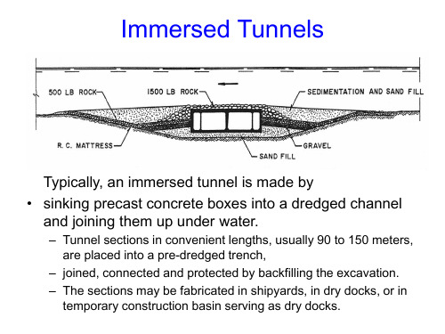
Immersed Tunnels
Typically, an immersed tunnel is made by • sinking precast concrete boxes into a dredged channel
and joining them up under water.
– Tunnel sections in convenient lengths, usually 90 to 150 meters, are placed into a pre-dredged trench,
• Tides and current effects of the waterway must be evaluated to determine conditions during dredging and tube sinking operations.
道路与桥梁工程中英文对照外文翻译文献

中英文对照外文翻译(文档含英文原文和中文翻译)Bridge research in EuropeA brief outline is given of the development of the European Union, together with the research platform in Europe. The special case of post-tensioned bridges in the UK is discussed. In order to illustrate the type of European research being undertaken, an example is given from the University of Edinburgh portfolio: relating to the identification of voids in post-tensioned concrete bridges using digital impulse radar.IntroductionThe challenge in any research arena is to harness the findings of different research groups to identify a coherent mass of data, which enables research and practice to be better focused. A particular challenge exists with respect to Europe where language barriers are inevitably very significant. The European Community was formed in the 1960s based upon a political will within continental Europe to avoid the European civil wars, which developed into World War 2 from 1939 to 1945. The strong political motivation formed the original community of which Britain was not a member. Many of the continental countries saw Britain’s interest as being purelyeconomic. The 1970s saw Britain joining what was then the European Economic Community (EEC) and the 1990s has seen the widening of the community to a European Union, EU, with certain political goals together with the objective of a common European currency.Notwithstanding these financial and political developments, civil engineering and bridge engineering in particular have found great difficulty in forming any kind of common thread. Indeed the educational systems for University training are quite different between Britain and the European continental countries. The formation of the EU funding schemes —e.g. Socrates, Brite Euram and other programs have helped significantly. The Socrates scheme is based upon the exchange of students between Universities in different member states. The Brite Euram scheme has involved technical research grants given to consortia of academics and industrial partners within a number of the states— a Brite Euram bid would normally be led by an industrialist.In terms of dissemination of knowledge, two quite different strands appear to have emerged. The UK and the USA have concentrated primarily upon disseminating basic research in refereed journal publications: ASCE, ICE and other journals. Whereas the continental Europeans have frequently disseminated basic research at conferences where the circulation of the proceedings is restricted.Additionally, language barriers have proved to be very difficult to break down. In countries where English is a strong second language there has been enthusiastic participation in international conferences based within continental Europe —e.g. Germany, Italy, Belgium, The Netherlands and Switzerland. However, countries where English is not a strong second language have been hesitant participants }—e.g. France.European researchExamples of research relating to bridges in Europe can be divided into three types of structure:Masonry arch bridgesBritain has the largest stock of masonry arch bridges. In certain regions of the UK up to 60% of the road bridges are historic stone masonry arch bridges originally constructed for horse drawn traffic. This is less common in other parts of Europe as many of these bridges were destroyed during World War 2.Concrete bridgesA large stock of concrete bridges was constructed during the 1950s, 1960s and 1970s. At the time, these structures were seen as maintenance free. Europe also has a large number of post-tensioned concrete bridges with steel tendon ducts preventing radar inspection. This is a particular problem in France and the UK.Steel bridgesSteel bridges went out of fashion in the UK due to their need for maintenance as perceived in the 1960s and 1970s. However, they have been used for long span and rail bridges, and they are now returning to fashion for motorway widening schemes in the UK.Research activity in EuropeIt gives an indication certain areas of expertise and work being undertaken in Europe, but is by no means exhaustive.In order to illustrate the type of European research being undertaken, an example is given from the University of Edinburgh portfolio. The example relates to the identification of voids in post-tensioned concrete bridges, using digital impulse radar.Post-tensioned concrete rail bridge analysisOve Arup and Partners carried out an inspection and assessment of the superstructure of a 160 m long post-tensioned, segmental railway bridge in Manchester to determine its load-carrying capacity prior to a transfer of ownership, for use in the Metrolink light rail system..Particular attention was paid to the integrity of its post-tensioned steel elements. Physical inspection, non-destructive radar testing and other exploratory methods were used to investigate for possible weaknesses in the bridge.Since the sudden collapse of Ynys-y-Gwas Bridge in Wales, UK in 1985, there has been concern about the long-term integrity of segmental, post-tensioned concrete bridges which may b e prone to ‘brittle’ failure without warning. The corrosion protection of the post-tensioned steel cables, where they pass through joints between the segments, has been identified as a major factor affecting the long-term durability and consequent strength of this type of bridge. The identification of voids in grouted tendon ducts at vulnerable positions is recognized as an important step in the detection of such corrosion.Description of bridgeGeneral arrangementBesses o’ th’ Barn Bridge is a 160 m long, three span, segmental, post-tensionedconcrete railway bridge built in 1969. The main span of 90 m crosses over both the M62 motorway and A665 Bury to Prestwick Road. Minimum headroom is 5.18 m from the A665 and the M62 is cleared by approx 12.5 m.The superstructure consists of a central hollow trapezoidal concrete box section 6.7 m high and 4 m wide. The majority of the south and central spans are constructed using 1.27 m long pre-cast concrete trapezoidal box units, post-tensioned together. This box section supports the in site concrete transverse cantilever slabs at bottom flange level, which carry the rail tracks and ballast.The center and south span sections are of post-tensioned construction. These post-tensioned sections have five types of pre-stressing:1. Longitudinal tendons in grouted ducts within the top and bottom flanges.2. Longitudinal internal draped tendons located alongside the webs. These are deflected at internal diaphragm positions and are encased in in site concrete.3. Longitudinal macalloy bars in the transverse cantilever slabs in the central span .4. Vertical macalloy bars in the 229 mm wide webs to enhance shear capacity.5. Transverse macalloy bars through the bottom flange to support the transverse cantilever slabs.Segmental constructionThe pre-cast segmental system of construction used for the south and center span sections was an alternative method proposed by the contractor. Current thinking suggests that such a form of construction can lead to ‘brittle’ failure of the ent ire structure without warning due to corrosion of tendons across a construction joint,The original design concept had been for in site concrete construction.Inspection and assessmentInspectionInspection work was undertaken in a number of phases and was linked with the testing required for the structure. The initial inspections recorded a number of visible problems including:Defective waterproofing on the exposed surface of the top flange.Water trapped in the internal space of the hollow box with depths up to 300 mm.Various drainage problems at joints and abutments.Longitudinal cracking of the exposed soffit of the central span.Longitudinal cracking on sides of the top flange of the pre-stressed sections.Widespread sapling on some in site concrete surfaces with exposed rusting reinforcement.AssessmentThe subject of an earlier paper, the objectives of the assessment were:Estimate the present load-carrying capacity.Identify any structural deficiencies in the original design.Determine reasons for existing problems identified by the inspection.Conclusion to the inspection and assessmentFollowing the inspection and the analytical assessment one major element of doubt still existed. This concerned the condition of the embedded pre-stressing wires, strands, cables or bars. For the purpose of structural analysis these elements、had been assumed to be sound. However, due to the very high forces involved,、a risk to the structure, caused by corrosion to these primary elements, was identified.The initial recommendations which completed the first phase of the assessment were:1. Carry out detailed material testing to determine the condition of hidden structural elements, in particularthe grouted post-tensioned steel cables.2. Conduct concrete durability tests.3. Undertake repairs to defective waterproofing and surface defects in concrete.Testing proceduresNon-destructi v e radar testingDuring the first phase investigation at a joint between pre-cast deck segments the observation of a void in a post-tensioned cable duct gave rise to serious concern about corrosion and the integrity of the pre-stress. However, the extent of this problem was extremely difficult to determine. The bridge contains 93 joints with an average of 24 cables passing through each joint, i.e. there were approx. 2200 positions where investigations could be carried out. A typical section through such a joint is that the 24 draped tendons within the spine did not give rise to concern because these were protected by in site concrete poured without joints after the cables had been stressed.As it was clearly impractical to consider physically exposing all tendon/joint intersections, radar was used to investigate a large numbers of tendons and hence locate duct voids within a modest timescale. It was fortunate that the corrugated steel ducts around the tendons were discontinuous through the joints which allowed theradar to detect the tendons and voids. The problem, however, was still highly complex due to the high density of other steel elements which could interfere with the radar signals and the fact that the area of interest was at most 102 mm wide and embedded between 150 mm and 800 mm deep in thick concrete slabs.Trial radar investigations.Three companies were invited to visit the bridge and conduct a trial investigation. One company decided not to proceed. The remaining two were given 2 weeks to mobilize, test and report. Their results were then compared with physical explorations.To make the comparisons, observation holes were drilled vertically downwards into the ducts at a selection of 10 locations which included several where voids were predicted and several where the ducts were predicted to be fully grouted. A 25-mm diameter hole was required in order to facilitate use of the chosen horoscope. The results from the University of Edinburgh yielded an accuracy of around 60%.Main radar sur v ey, horoscope verification of v oids.Having completed a radar survey of the total structure, a baroscopic was then used to investigate all predicted voids and in more than 60% of cases this gave a clear confirmation of the radar findings. In several other cases some evidence of honeycombing in the in site stitch concrete above the duct was found.When viewing voids through the baroscopic, however, it proved impossible to determine their actual size or how far they extended along the tendon ducts although they only appeared to occupy less than the top 25% of the duct diameter. Most of these voids, in fact, were smaller than the diameter of the flexible baroscopic being used (approximately 9 mm) and were seen between the horizontal top surface of the grout and the curved upper limit of the duct. In a very few cases the tops of the pre-stressing strands were visible above the grout but no sign of any trapped water was seen. It was not possible, using the baroscopic, to see whether those cables were corroded.Digital radar testingThe test method involved exciting the joints using radio frequency radar antenna: 1 GHz, 900 MHz and 500 MHz. The highest frequency gives the highest resolution but has shallow depth penetration in the concrete. The lowest frequency gives the greatest depth penetration but yields lower resolution.The data collected on the radar sweeps were recorded on a GSSI SIR System 10.This system involves radar pulsing and recording. The data from the antenna is transformed from an analogue signal to a digital signal using a 16-bit analogue digital converter giving a very high resolution for subsequent data processing. The data is displayed on site on a high-resolution color monitor. Following visual inspection it is then stored digitally on a 2.3-gigabyte tape for subsequent analysis and signal processing. The tape first of all records a ‘header’ noting the digital radar settings together with the trace number prior to recording the actual data. When the data is played back, one is able to clearly identify all the relevant settings —making for accurate and reliable data reproduction.At particular locations along the traces, the trace was marked using a marker switch on the recording unit or the antenna.All the digital records were subsequently downloaded at the University’s NDT laboratory on to a micro-computer.(The raw data prior to processing consumed 35 megabytes of digital data.)Post-processing was undertaken using sophisticated signal processing software. Techniques available for the analysis include changing the color transform and changing the scales from linear to a skewed distribution in order to highlight、突出certain features. Also, the color transforms could be changed to highlight phase changes. In addition to these color transform facilities, sophisticated horizontal and vertical filtering procedures are available. Using a large screen monitor it is possible to display in split screens the raw data and the transformed processed data. Thus one is able to get an accurate indication of the processing which has taken place. The computer screen displays the time domain calibrations of the reflected signals on the vertical axis.A further facility of the software was the ability to display the individual radar pulses as time domain wiggle plots. This was a particularly valuable feature when looking at individual records in the vicinity of the tendons.Interpretation of findingsA full analysis of findings is given elsewhere, Essentially the digitized radar plots were transformed to color line scans and where double phase shifts were identified in the joints, then voiding was diagnosed.Conclusions1. An outline of the bridge research platform in Europe is given.2. The use of impulse radar has contributed considerably to the level of confidence in the assessment of the Besses o’ th’ Barn Rail Bridge.3. The radar investigations revealed extensive voiding within the post-tensioned cable ducts. However, no sign of corrosion on the stressing wires had been found except for the very first investigation.欧洲桥梁研究欧洲联盟共同的研究平台诞生于欧洲联盟。
Lesson 07 Bridge(土木工程专业英语)

在森林区,有粗壮的木材或圆木可利用,桥梁很可能由一 根或几根平行的圆木组成,可能为了更好的行走会在上面铺上 交叉的树枝或草席。
In tropical regions of India, Africa, and South America, fibrous vines were used to build suspension bridges.
constructed by primitive peoples in isolated regions.
人类修建的第一批桥梁可能类似于那些在隔离的地区原 始人还在修建的桥梁。
The tools and building skills of early man, like those of primitive peoples today, were so elementary that he was undoubtedly forced to use easily transportable materials that could be put in p1ace with a minimum of forming and shaping.
barge 游艇
isolated 孤立的t 倾斜 swift 迅速 subsoil 地基;地下
土木工程专业英语
Bridge
Bridge is a structure that spans obstacles, such as rivers and valleys, to
在印度、非洲和南美洲的热带地区,坚韧的藤条被用来修 建悬索桥。
The vines were tied to trees or rocks on each side of the stream or valley to be crossed. One or more vines were used to tread on. Other vines, strung several feet higher, were used for hand holds.
桥梁与隧道-USDepartmentofTransportation

⏹任务描述 确保货物和人员在纽约市所有道路和桥梁上安全有效通行。
⏹交通局负责维护和维修 5 个区 790 座城市所有车行和人行桥梁。
纽约市交通部1865 - 19151915 - 1965现有桥梁桥梁类型数量主干道208系统外(当地)389人行107航道 51可移动 25隧道 6东河 4桥梁与隧道操作各种桥梁类型⏹25 座可移动桥梁竖直旋转式 (12)、水平旋转式 (7)、垂直升降式 (4)、伸缩式 (2)6,500 次开启/年根据需要 24 / 7 全天候开启移动人员操作⏹电动隧道维护与维修泵与通风维护R av = 常量_____________维护成本CM= ?变质率重建维修5/3($450ml./450) + 2/1 ($20ml./150) = 15 ml. ft2 ro--» ro = 0.13工作人员⏹操作 – 100(桥梁操作员 + 电气技师)⏹检查 – 29(检查员和员工)⏹标志 – 15(工程师 + 员工)⏹维护:维修 – 135(工程师 + 熟练工)预防性维护 – 135(工人 + 操作工程师)就业再培训局项目经理 – 18(工程师 + 熟练工)⏹员工总人数: 432⏹桥梁喷漆内部 – 47(喷漆工 + 员工)合同工 - 9(工程师 + 员工)任务影响* 碎屑清除6.1% 清扫5.3% 清洁桥台和支墩 8.1% 清洁开放式格式板 7.0% 清洁膨胀结9.1% 清洗桥板和浪溅区 5.1% 喷漆4.2% 点喷漆 3.7% 任务 影响* 下水道清洁 10.6% 人行道和路缘石维修 2.5% 人行道和裂缝修补 12.2% 清洗底面 15.9% 机械设备维护6.7% 更换磨损表面 3.5%*影响桥梁检定纽约市桥梁预防性维护管理系统——纽约市高等院校土木工程部联盟(1999 年更新) 桥梁维护与维修⏹最佳管理实践通知:美国海岸警卫队;纽约环境保护局;纽约市警察局。
专业英语-隧道施工专业名词

隧道工程相关专业英语词汇隧道 tunnel●隧道工程 tunnel engineering●铁道隧道 railway tunnel●公路隧道 highway tunnel●地铁隧道 subway tunnel ; underground railway tunnel;metro tunnel●人行隧道 pedestrian tunnel●水工隧洞 ;输水隧道 hydraulic tunnel●山岭隧道 mountain tunnel●水下隧道 subaqueous tunnel●海底隧道 ;水下隧道 submarine tunnel;underwater tunnel●土质隧道 earth tunnel●岩石隧道 rock tunnel●浅埋隧道 shallow tunnel;shallow-depth tunnel ;shallow burying tunnel●深埋隧道 deep tunnel;deep-depth tunnel ; deep burying tunnel ●偏压隧道 unsymmetrical loading tunnel●马蹄形隧道 ;拱形隧道 horse-shoe tunnel ; arch tunnel●圆形隧道 circular tunnel●矩形隧道 rectangular section tunnel●大断面隧道 largecross-section tunnel●长隧道 long tunnel●双线隧道 twin-track tunnel ; double track tunnel●曲线隧道 curved tunnel●明洞 open tunnel;open cut tunnel;tunnel without cover;gallery隧道施工方法 tunnel construction method●钻爆法 drilling and blasting method●新奥法 natm;new austrian tunnelling method●盾构法 shield driving method;shield method●顶进法 pipe jacking method ; jack-in method●浅埋暗挖法 sallow buried-tunnelling method●明挖法 cut and cover tunneling;open cut method●地下连续墙法 underground diaphragm wall method;underground wall method●冻结法 freezing method●沉埋法 immersed tube method●管棚法 pipe-shed method隧道勘测 tunnel survey●超前探测 drift boring●工程地质勘测 ;工程地质勘探 engineering geological prospecting●隧道测量 tunnel survey●施工测量 construction survey●断面测量 section survey●隧道设计 tunnel design●隧道断面 tunnel section●安全系数 safety coefficient●隧道力学 tunnel mechanics●隧道结构 tunnel structure ●隧道洞口设施 facilities of tunnel portal●边墙 side wall●拱顶 arch crown●拱圈 tunnel arch●仰拱 inverted arch●底板 base plate;floor●隧道埋深 depth of tunnel●隧道群 tunnel group●隧道施工 tunnel construction●隧道开挖 tunnel excavation●分部开挖 partial excavation●大断面开挖 large cross-section excavation●全断面开挖 full face tunnelling●开挖面 excavated surface围岩压力 ground pressure;●surrounding rock pressure●围岩变形 surrounding rock deformation●围岩破坏 surrounding rock failure●软弱围岩 weak surrounding rock支护 support●锚喷支护 anchor bolt-spray support●锚杆支护 anchor bolt-support;anchor bolt support ●喷射混凝土支护 ;喷射砼支护 shotcrete support;sprayed concrete support●配筋喷射混凝土支护 ;配筋喷射砼支护 reinforced sprayed concrete support●钢架喷射混凝土支护 ;钢架喷射砼支护 rigid-frame shotcrete support●掘进工作面支护 excavation face support●超前支护 advance support●管棚支护 pipe-shed support;pipe roofing support●胶结型锚杆 adhesive anchor bolt●砂浆锚杆 mortar bolt●树脂锚杆 resin anchored bolt●摩擦型锚杆 friction anchor bolt●楔缝式锚杆 slit wedge type rock bolt●涨壳式锚杆 expansion type anchor bolt●机械型锚杆 mechanical anchor bolt●预应力锚杆 prestressed anchor bolt●土层锚杆 soil bolt 岩石锚杆 rock bolt衬砌 lining●整体式衬砌 integral tunnel lining;integral lining●拼装式衬砌 precast lining●组合衬砌 composite lining●挤压混凝土衬砌 shotcrete tunnel lining ;extruding concrete tunnel lining●混凝土衬砌 ;砼衬砌 concrete lining●喷锚衬砌 shotcrete and bolt lining;shotcrete bolt lining隧道通风 tunnel ventilation●施工通风 construction ventilation●运营通风 operation ventilation●机械通风 mechanical ventilation●自然通风 natural ventilation●隧道射流式通风 efflux ventilation for tunnel ;tunnel efflux ventilation;tunnel injector type ventilation●隧道通风帘幕 curtain for tunnel ventilation;ventilation curtain ●通风设备 ventilation equipment隧道照明 tunnel illuminationtunnel lighting照明设备 lighting equipment隧道防水 tunnel waterproofing;waterproofing of tunnel●防水板 waterproofing board;waterproof board;waterproof sheet ●防水材料 waterproof material●隧道排水 tunnel drainage●排水设备 drainage facilites●隧道病害 tunnel defect●衬砌裂损 lining split;●隧道漏水 water leakage of tunnel;tunnel leak●坍方 landslide;slip●地面塌陷 land yielding●涌水 gushing water●隧道养护 tunnel maintenance●堵漏 leaking stoppage●注浆 grouting●化学注浆 chemical grouting●防寒 cold-proof●整治 regulation●限界检查 clearance examination;checking of●clearance;clearance check measurement●隧道管理系统 tunnelling management system●隧道环境 tunnel environment隧道试验 ;隧道实验 tunnel test●试验段 ;实验段 test section●隧道监控量测 ;隧道监控测量 tunnel monitoring measurement ●收敛 convergence●隧道安全 tunnel safety●隧道防火 tunnel fire proofing●火灾 fire hazard●消防 fire fighting●隧道防灾设施 tunnel disaster prevention equipment;tunnel anti-disaster equipment●报警装置 ;报警器 alarming device;warning device●通过隧道 passing tunnel●避车洞 refuge hole●避难洞 ;避车洞 refuge recess;refuge hole电气化铁道工程 ;电气化铁路工程 electrified railway construction●直流电气化铁道 dc electrified railway●交流电气化铁道 ;交流电气化铁路 a.c.electrification railway●低频电气化铁道 low frequency electrified railway●工频电气化铁路 industry frequency electrified railway●电压制 voltage system电流制 current system。
隧道工程英语专业词汇

隧道工程英语专业词汇隧道工程tunnel engineering隧道tunnel铁路隧道railway tunnel公路隧道highway tunnel地铁隧道subway tunnel;underground railway tunnel;metro tunnel 人行隧道pedestrian tunnel水工隧洞hydraulic tunnel输水隧道raulic tunnel山岭隧道mountain tunnel水下隧道subaqueous tunnel海底隧道水下隧道submarinetunnel;underwater tunnel 土质隧道earth tunnel岩石隧道rock tunnel浅埋隧道shallow tunnel;shallow-depthtunnel;s hallow burying tunnel深埋隧道deeptunnel;deep-depthtunnel;dee p burying tunnel偏压隧道unsymmetrical loading tunnel马蹄形隧道拱形隧道horse-shoe tunnel;arch tunnel圆形隧道circular tunnel矩形隧道rectangular section tunnel 大断面隧道largecross-section tunnel长隧道long tunnel双线隧道twin-track tunnel;double track tunnel曲线隧道curved tunnel明洞open tunnel;open cut tunnel;tunnel without cover;gallery隧道勘测tunnel survey超前探测drift boring工程地质勘测工程地质勘探engineering geological prospecting隧道测量tunnel survey施工测量construction survey断面测量section survey隧道设计tunnel design隧道断面tunnel section安全系数safety coefficient隧道力学tunnel mechanics隧道结构tunnel structure隧道洞口设施facilities of tunnel portal 边墙side wall拱顶arch crown拱圈tunnel arch 仰拱inverted arch底板base plate;floor隧道埋深depth of tunnel隧道群tunnel group隧道施工tunnel construction隧道开挖tunnel excavation分部开挖partial excavation大断面开挖large cross-section excavation全断面开挖full face tunnelling开挖面excavated surface隧道施工方法tunnel construction method 钻爆法drilling and blasting method 新奥法natm;newaustriantunnelling method盾构法shield driving method;shield method顶进法pipe jacking method;jack-in method浅埋暗挖法sallow buried-tunnelling method明挖法cut and cover tunneling;open cut method地下连续墙法underground diaphragm wall method;underground wall method冻结法freezing method沉埋法immersed tube method管棚法pipe-shed method综合机械化掘进comprehensive mechanized excavation辅助坑道auxiliary adit;service gallery 平行坑道parallel adit竖井shaft斜井sloping shaft;inclined shaft 导坑heading衬砌工艺lining process喷锚锚喷anchor bolt spray;anchor bolt-spray管段tube section接缝joint地层加固reinforcing of natural ground 弃碴ballast piling施工监控construction monitor control 超挖overbreak欠挖underbreak施工进度construction progress隧道贯通tunnel holing-through工期work period隧道施工机械tunnel construction machinery隧道掘进机tunnellingmachine;tunnelbor ing machine;tbm单臂掘进机single cantilever tunnelling machine全断面掘进机full face tunnel boring machine隧道钻眼爆破机械machine for tunnel drilling and blasting operation装碴运输机械loading-conveying ballast equipment衬砌机械lining mechanism钢模板steel form模板台车formworking jumbo混凝土喷射机砼喷射机concrete sprayer盾构shield泥水盾构slurry shield气压盾构air pressure shield挤压闭胸盾构shotcrete closed shield 土压平衡盾构soil pressure balancing shield 注浆机械grouting machine凿岩机rock drilling machine;air hammer drill凿岩台车drill jumbo;rock drilling jumbo围岩surrounding rock围岩分类surrounding rock classification围岩加固surrounding rock consolidation围岩稳定surrounding rock stability围岩应力surrounding rock stress围岩压力pressure of surrounding rock 山体压力围岩压力ground pressure;surrounding rock pressure围岩变形surrounding rock deformation围岩破坏surrounding rock failure软弱围岩weak surrounding rock支护support锚喷支护anchor bolt-spray support 锚杆支护anchor bolt-support;anchor bolt support喷射混凝土支护喷射砼支护shotcrete support;sprayed concrete support配筋喷射混凝土支护配筋喷射砼支护reinforced sprayed concrete support钢架喷射混凝土支护钢架喷射砼支护rigid-frame shotcrete support掘进工作面支护excavation face support超前支护advance support管棚支护pipe-shed support;pipe roofing support胶结型锚杆adhesive anchor bolt砂浆锚杆mortar bolt树脂锚杆resin anchored bolt摩擦型锚杆friction anchor bolt楔缝式锚杆slit wedge type rock bolt涨壳式锚杆expansion type anchor bolt 机械型锚杆mechanical anchor bolt预应力锚杆prestressed anchor bolt土层锚杆soil bolt岩石锚杆rock bolt衬砌lining整体式衬砌integral tunnel lining;integral lining拼装式衬砌precast lining组合衬砌composite lining挤压混凝土衬砌挤压砼衬砌shotcrete tunnellining;extruding concrete tunnel lining混凝土衬砌砼衬砌concrete lining喷锚衬砌shotcrete and boltlining;shotcrete bolt lining 隧道通风tunnel ventilation施工通风construction ventilation运营通风operation ventilation机械通风mechanical ventilation自然通风natural ventilation隧道射流式通风隧道射流通风efflux ventilation for tunnel;tunnel efflux ventilation;tunnel injector type ventilation隧道通风帘幕curtain for tunnel ventilation;ventilation curtain 通风设备ventilation equipment隧道照明tunnel illumination;tunnel lighting照明设备lighting equipment隧道防水Tunnelwaterproofing;waterpr oofing of tunnel防水板waterproofingboard;waterproofboard;water proof sheet防水材料waterproof material隧道排水tunnel drainage排水设备drainage facilites隧道病害tunnel defect衬砌裂损lining split;lining **ing隧道漏水water leakage of tunnel;tunnel leak坍方landslide;slip地面塌陷land yielding涌水gushing water隧道养护tunnel maintenance堵漏leaking stoppage注浆grouting化学注浆chemical grouting防寒cold-proof整治regulation限界检查clearance examination;checking of clearance;clearance check measurement隧道管理系统tunnelling management system隧道环境tunnel environment隧道试验隧道实验tunnel test试验段实验段test section隧道监控量测隧道监控测量tunnel monitoring measurement收敛convergence隧道安全tunnel safety隧道防火tunnel fire proofing火灾fire hazard消防fire fighting隧道防灾设施tunnel disaster prevention equipment;tunnelanti-disaster equipment 报警装置报警器alarming device;warning device通过隧道passing tunnel避车洞refuge hole避难洞避车洞refuge recess;refuge hole 电气化铁道工程电气化铁路工程electrified railway construction电气化铁道电气化铁路electrified railway直流电气化铁道dc electrified railway交流电气化铁道交流电气化铁路a.c.electrification railway低频电气化铁道low frequency electrified railway工频电气化铁道工频电气化铁路industry frequency electrified railway电压制voltage system电流制current system。
道路与桥梁专业外文翻译中英对照

本科毕业设计论文专业外文翻译专业名称:土木工程专业道路与桥梁年级班级:道桥08-5班学生姓名:指导教师:二○一二年五月十八日Geometric Design of HighwaysThe road is one kind of linear construction used for travel. It is made of the roadbed, the road surface, the bridge, the culvert and the tunnel. In addition, it also has the crossing of lines, the protective project and the traffic engineering and the route facility.The roadbed is the base of road surface, road shoulder, side slope, side ditch foundations. It is stone material structure, which is designed according to route's plane position .The roadbed, as the base of travel, must guarantee that it has the enough intensity and the stability that can prevent the water and other natural disaster from corroding.The road surface is the surface of road. It is single or complex structure built with mixture. The road surface require being smooth, having enough intensity, good stability and anti-slippery function. The quality of road surface directly affects the safe, comfort and the traffic.Highway geometry designs to consider Highway Horizontal Alignment, Vertical Alignment two kinds of linear and cross-sectional composition of coordination, but also pay attention to the smooth flow of the line of sight, etc. Determine the road geometry, consider the topography, surface features, rational use of land and environmental protection factors, to make full use of the highway geometric components of reasonable size and the linear combination.DesignThe alignment of a road is shown on the plane view and is a series of straight lines called tangents connected by circular. In modern practice it is common to interpose transition or spiral curves between tangents and circular curves.Alignment must be consistent. Sudden changes from flat to sharp curves and long tangents followed by sharp curves must be avoided; otherwise, accident hazards will be created. Likewise, placing circular curves of different radii end to end compound curves or having a short tangent between two curves is poor practice unless suitable transitions between them are provided. Long, flat curves are preferable at all times, as they are pleasing in appearance and decrease possibility of future obsolescence. However, alignment without tangents is undesirable on two-lane roads because some drivers hesitate to pass on curves. Long, flat curves should be used for small changes in direction, as short curves appear as “kink”. Also horizontal and vertical alignment must be considered together, not separately. For example, a sharp horizontal curve beginning near a crest can create a serious accident hazard.A vehicle traveling in a curved path is subject to centrifugal force. This is balanced by an equal and opposite force developed through cannot exceed certain maximums, and these controls place limits on the sharpness of curves that can be used with a design speed. Usually the sharpness of a given circular curve is indicated by its radius. However, for alignment design, sharpness is commonly expressed in terms of degree of curve, which is the central angle subtended by a 100-ft length of curve. Degree of curve is inversely proportional to the radius.Tangent sections of highways carry normal cross slope; curved sections are super elevated. Provision must be made for gradual change from one to the other. This usually involves maintaining the center line of each individual roadway at profile grade while raising the outer edge and lowering the inner edge to produce the desired super elevation is attained some distance beyond the point of curve.If a vehicle travels at high speed on a carefully restricted path made up of tangents connected by sharp circular curve, riding is extremely uncomfortable. As the car approaches a curve, super elevation begins and the vehicle is tilted inward, but the passenger must remain vertical since there is on centrifugal force requiring compensation. When the vehicle reaches the curve, full centrifugal force develops at once, and pulls the rider outward from his vertical position. To achieve a position of equilibrium he must force his body far inward. As the remaining super elevation takes effect, further adjustment in position is required. This process is repeated in reverse order as the vehicle leaves the curve. When easement curves are introduced, the change in radius from infinity on the tangent to that of the circular curve is effected gradually so that centrifugal force also develops gradually. By careful application of super elevation along the spiral, a smooth and gradual application of centrifugal force can be had and the roughness avoided.Easement curves have been used by the railroads for many years, but their adoption by highway agencies has come only recently. This is understandable. Railroad trains must follow the precise alignment of the tracks, and the discomfort described here can be avoided only by adopting easement curves. On the other hand, the motor-vehicle operator is free to alter his lateral position on the road and can provide his own easement curves by steering into circular curves gradually. However, this weaving within a traffic lane but sometimes into other lanes is dangerous. Properly designed easement curves make weaving unnecessary. It is largely for safety reasons, then, that easement curves have been widely adopted by highway agencies.For the same radius circular curve, the addition of easement curves at the ends changes the location of the curve with relationto its tangents; hence the decision regarding their use should be made before the final location survey. They point of beginning of an ordinary circular curve is usually labeled the PC point of curve or BC beginning of curve. Its end is marked the PT point of tangent or EC end of curve. For curves that include easements, the common notation is, as stationing increases: TS tangent to spiral, SC spiral to circular curve, CS circular curve to spiral, and ST spiral go tangent.On two-lane pavements provision of a wilder roadway is advisable on sharp curves. This will allow for such factors as 1 the tendency for drivers to shy away from the pavement edge, 2 increased effective transverse vehicle width because the front and rear wheels do not track, and 3 added width because of the slanted position of the front of the vehicle to the roadway centerline. For 24-ft roadways, the added width is so small that it can be neglected. Only for 30mph design speeds and curves sharper than 22°does the added width reach 2 ft. For narrower pavements, however, widening assumes importance even on fairly flat curves. Recommended amounts of and procedures for curve widening are given in Geometric Design for Highways.2. GradesThe vertical alignment of the roadway and its effect on the safe and economical operation of the motor vehicle constitute one of the most important features of road design. The vertical alignment, which consists of a series of straight lines connected by vertical parabolic or circular curves, is known as the “grade line.” When the grade line is increasing from the horizontal it is known as a “plus grade,” and when it is decreasing from the horizontal it is known as a “minus grade.” In analyzing grade and grade controls, the designer usually studies the effect of change in grade on the centerline profile.In the establishment of a grade, an ideal situation is one inwhich the cut is balanced against the fill without a great deal of borrow or an excess of cut to be wasted. All hauls should be downhill if possible and not too long. The grade should follow the general terrain and rise and fall in the direction of the existing drainage. In mountainous country the grade may be set to balance excavation against embankment as a clue toward least overall cost. In flat or prairie country it will be approximately parallel to the ground surface but sufficiently above it to allow surface drainage and, where necessary, to permit the wind to clear drifting snow. Where the road approaches or follows along streams, the height of the grade line may be dictated by the expected level of flood water. Under all conditions, smooth, flowing grade lines are preferable to choppy ones of many short straight sections connected with short vertical curves.Changes of grade from plus to minus should be placed in cuts, and changes from a minus grade to a plus grade should be placed in fills. This will generally give a good design, and many times it will avoid the appearance of building hills and producing depressions contrary to the general existing contours of the land. Other considerations for determining the grade line may be of more importance than the balancing of cuts and fills.Urban projects usually require a more detailed study of the controls and finer adjustment of elevations than do rural projects. It is often best to adjust the grade to meet existing conditions because of the additional expense of doing otherwise.In the analysis of grade and grade control, one of the most important considerations is the effect of grades on the operating costs of the motor vehicle. An increase in gasoline consumption and a reduction in speed are apparent when grades are increase in gasoline consumption and a reduction in speed is apparent when grades are increased. An economical approach would be to balancethe added annual cost of grade reduction against the added annual cost of vehicle operation without grade reduction. An accurate solution to the problem depends on the knowledge of traffic volume and type, which can be obtained only by means of a traffic survey.While maximum grades vary a great deal in various states, AASHTO recommendations make maximum grades dependent on design speed and topography. Present practice limits grades to 5 percent of a design speed of 70 mph. For a design speed of 30 mph, maximum grades typically range from 7 to 12 percent, depending on topography. Wherever long sustained grades are used, the designer should not substantially exceed the critical length of grade without the provision of climbing lanes for slow-moving vehicles. Critical grade lengths vary from 1700 ft for a 3 percent grade to 500 ft for an 8 percent grade.Long sustained grades should be less than the maximum grade on any particular section of a highway. It is often preferred to break the long sustained uniform grade by placing steeper grades at the bottom and lightening the grade near the top of the ascent. Dips in the profile grade in which vehicles may be hidden from view should also be avoided. Maximum grade for highway is 9 percent. Standards setting minimum grades are of importance only when surface drainage is a problem as when water must be carried away in a gutter or roadside ditch. In such instances the AASHTO suggests a minimum of %.3. Sight DistanceFor safe vehicle operation, highway must be designed to give drivers a sufficient distance or clear version ahead so that they can avoid unexpected obstacles and can pass slower vehicles without danger. Sight distance is the length of highway visible ahead to the driver of a vehicle. The concept of safe sight distance has two facets: “stopping” or “no passing” and “passing”.At times large objects may drop into a roadway and will do seriousdamage to a motor vehicle that strikes them. Again a car or truck may be forced to stop in the traffic lane in the path of following vehicles. In dither instance, proper design requires that such hazards become visible at distances great enough that drivers can stop before hitting them. Further more, it is unsafe to assume that one oncoming vehicle may avoid trouble by leaving the lane in which it is traveling, for this might result in loss of control or collision with another vehicle.Stopping sight distance is made up of two elements. The first is the distance traveled after the obstruction comes into view but before the driver applies his brakes. During this period of perception and reaction, the vehicle travels at its initial velocity. The second distance is consumed while the driver brakes the vehicle to a stop. The first of these two distances is dependent on the speed of the vehicle and the perception time and brake-reaction time of the operator. The second distance depends on the speed of the vehicle; the condition of brakes, times, and roadway surface; and the alignment and grade of the highway.On two-lane highways, opportunity to pass slow-moving vehicles must be provided at intervals. Otherwise capacity decreases and accidents increase as impatient drivers risk head-on collisions by passing when it is unsafe to do so. The minimum distance ahead that must be clear to permit safe passing is called the passing sight distance. In deciding whether or not to pass another vehicle, the driver must weigh the clear distance available to him against the distance required to carry out the sequence of events that make up the passing maneuver. Among the factors that will influence his decision are the degree of caution that he exercises and the accelerating ability of his vehicle. Because humans differ markedly, passing practices, which depend largely on human judgment and behavior rather than on the laws of mechanics, vary considerablyamong drivers.The geometric design is to ensure highway traffic safety foundation, the highway construction projects around the other highway on geometric design, therefore, in the geometry of the highway design process, if appear any unsafe potential factors, or low levels of combination of design, will affect the whole highway geometric design quality, and the safety of the traffic to bring adverse impact. So, on the geometry of the highway design must be focus on.公路几何设计公路是供汽车或其他车辆行驶的一种线形带状结构体.它是由路基、路面、桥梁、涵洞和隧道组成.此外,它还有路线交叉、工程和交通工程及沿线设施.路基是路面、路肩、边坡、等部分的基础.它是按照路线的平面位置在地面上开挖和成的土物.路基作为行车部分的基础,必须保证它有足够的强度和稳定性,可以防止水及其他自然灾害的侵蚀.路面是公路表面的部分.它是用混合料铺筑的单层或多层结构物.路面要求光滑,具有足够的强度,稳定性好和抗湿滑功能.路面质量的好环,直接影响到行车的安全性、舒适性和通行.公路几何线形设计要考虑公路平面线形、纵断面线形两种线形以及横断面的组成相协调,还要注意视距的畅通等等.确定公路几何线形时,在考虑地形、地物、土地的合理利用及环境保护因素时,要充分利用公路几何组成部分的合理尺寸和线形组合.1、线形设计道路的线形反映在平面图上是由一系列的直线和与直线相连的圆曲线构成的.现代设计时常在直线与圆曲线之间插入缓和曲线.线形应是连续的,应避免平缓线形到小半径曲线的突变或者长直线末端与小半径曲线相连接的突然变化,否则会发生交通事故.同样,不同半径的圆弧首尾相接曲线或在两半径不同的圆弧之间插入短直线都是不良的线形,除非在圆弧之间插入缓和曲线.长而平缓的曲线在任何时候都是可取的,因为这种曲线线形优美,将来也不会废弃.然而,双向道路线形全由曲线构成也是不理想的,因为一些驾驶员通过曲线路段时总是犹豫.长而缓的曲线应用在拐角较小的地方.如果采用短曲线,则会出现“扭结”.另外,线路的平、纵断面设计应综合考虑,而不应只顾其一,不顾其二,例如,当平曲线的起点位于竖曲线的顶点附近时将会产生严重的交通事故.行驶在曲线路段上的车辆受到离心力的作用,就需要一个大小相同方向相反的由超高和侧向磨擦提供的力抵消它,这些控制值对于某一规定设计车速可能采用曲线的曲率作了限制.通常情况下,某一圆曲线的曲率是由其半径来体现的.而对于线形设计而言,曲率常常通过曲线的程度来描述,即100英尺长的曲线所对应的中心角,曲线的程度与曲线的半径成反比.公路的直线地段设置正常的路拱,而曲线地段则设置超高,在正常断面与超高断面之间必须设置过渡渐变路段.通常的做法是维持道路每一条中线设计标高不变,通过抬高外侧边缘,降低内侧边缘以形成所需的超高,对于直线与圆曲线直接相连的线形,超高应从未到达曲线之前的直线上开始,在曲线顶点另一端一定距离以外达到全部超高.如果车辆以高速度行驶在直线与小半径的圆曲线相连的路段,行车是极不舒服.汽车驶近曲线路段时,超高开始,车辆向内侧倾斜,但乘客须维持身体的垂直状态,因为此时未受到离心力的作用.当汽车到达曲线路段时,离心力突然产生,迫使乘客向外倾斜,为了维持平衡,乘客必须迫使自己的身体向内侧倾斜.由于剩余超高发挥作用,乘客须作进一步的姿势的调整.当汽车离开曲线时,上述过程刚好相反.插入缓和曲线后,半径从无穷大逐渐过渡到圆曲线上的某一固定值,离心力逐渐增大,沿缓和曲线心设置超高,离心力平稳逐渐增加,避免了行车颠簸.缓和曲线在铁路上已经使用多年,但在公路上最近才得以应用,这是可以理解的.火车必须遵循精确的运行轨道,采用缓和曲线后,上述那种不舒服的感觉才能消除.然而,汽车司机在公路上可以随意改变侧向位置,通过迂回进入圆曲线来为自己提供缓和曲线.但是在一个车道上有时在其他车道上做这种迂回行驶是非常危险的.设计合理的缓和曲线使得上述迂回没有必要.主要是出于安全原因,公路部门广泛采用了缓和曲线.对于半径相同的圆曲线来说,在未端加上缓和曲线就会改变曲线与直线的相关位置,因此应在最终定线勘测之前应决定是否采用缓和曲线.一般曲线的起点标为PC或BC,终点标为PT或EC.对含有缓和曲线的曲线,通常的标记配置增为:TC、SC、CS和ST.对于双向道路,急弯处应增加路面宽度,这主要基于以下因素:1驾驶员害怕驶出路面边缘;2由于车辆前轮和后轮的行驶轨迹不同,车辆有效横向宽度加大;3车辆前方相对于公路中线倾斜而增加的宽度.对于宽度为24英尺的道路,增加的宽度很小,可以忽略.只有当设计车速为30mile/h,且曲度大于22℃时,加宽可达2英尺.然而,对于较窄的路面,即使是在较平缓的曲线路段上,加宽也是很重要推荐加宽值及加宽设计见公路线形设计2、纵坡线公路的竖向线形及其对车辆运行的安全性和经济性的影响构成了公路设计中最重要的要素之一.竖向线形由直线和竖向抛物线或圆曲线组成,称为纵坡线.纵坡线从水平线逐渐上升时称为坡度变化的影响.在确定坡度时最理想的情况是挖方与填方平衡,没有大量的借方或弃方.所有运土都尽可能下坡运并且距离不长,坡度应随地形而变,并且与既有排水系统的升、降方向一致.在山区,坡度要使得挖填平衡以使总成本最低.在平原或草原地区,坡度与地表近似平行,介是高于地表足够的高度,以利于路面排水,苦有必要,可利用风力来清除表面积雪.如公路接近或沿河流走行,纵坡线的高度由预期洪水位来决定.无论在何种情况下,平缓连续的坡度线要比由短直线段连接短竖曲线构成的不断变向的坡度线好得多.由上坡向下坡变化的路段应设在挖方路段,而由下坡向上坡变化的路段应设在填方路段,这样的线形设计较好,往往可以避免形成与现状地貌相反的圭堆或是凹地.与挖填方平衡相比,在确定纵坡线时,其他考虑则重要得多.城市项目通常比农村项目要求对控制要素进行更详尽的研究,对高程进行更细致地调整.一般来说,设计与现有条件相符的坡度较好,这样可避免一些不必要的花费.在坡度的分析和控制中,坡度对机动车运行费用的影响是最重要的考虑因素之一.坡度增大油耗显然增大,车速就要减慢.一个较为经济的方案则可使坡度减小而增加的年度成本与坡度不减而增加的车辆运行年度成本之间相平衡.这个问题的准确方法取决于对交通流量和交通类型的了解,这只有通过交通调查才能获知.在不同的州,最大纵坡也相差悬殊,AASHTO标准建议由设计车速和地形来选择最大纵坡.现行设计以设计车速为70mile/h时最大纵坡为5%,设计车速30mile/h时,根据地形不同,最大纵坡一般为7%-12%.当采用较长的待续爬坡时,在没有为慢行车辆提供爬坡道时,坡长不能够超过临界坡长.临界坡长可从3%纵坡的1700英尺变化至8%纵坡的500英尺.持续长坡的坡度必须小于公路任何一个断面的最大坡度,通常将长的持续单一纵坡断开,设计成底部为一陡坡,而接近坡顶则让坡度减小.同时还要避免由于断面倾斜而造成的视野受阻.调整公路的最大纵坡为9%只有当路面排水成问题时,如水必须排至边沟或排水沟,最小坡度标准才显示其重要性.这种情况下,AASHTO标准建议最小坡度为%.3、视距为保证行车安全,公路设计必须使得驾驶员视线前方有足够的一段距离,使他们能够避让意外的障碍物,或者安全地超车.视距就是车辆驾驶员前方可见的公路长度.安全视距具有两方面含义:“停车视距”或“不超车视距”或“超车视距”.有时,大件物体也许会掉到路上,会对撞上去的车辆造成严重的危害.同样,轿车或卡车也可能会被一溜车辆阻在车道上.无论是哪种情况发生,合理设计要求驾驶员在一段距离以外就能看见这种险情,并在撞上去之前把车刹住.此外,认为车辆通过离开所行驶的车道就可以躲避危险的想法是不安全的,因为这会导致车辆失控或与另一辆车相撞.停车视距由两部分组成:第一部分是当驾驶员发现障碍物面作出制动之前驶过的一段距离,在这一察觉与反应阶段,车辆以其初始速度行驶;第二部分是驾驶员刹车后车辆所驶过的一段距离.第一部分停车视距取决于车速及驾驶员的察觉时间和制动时间.第二部分停车视距取决于车速、刹车、轮胎、路面的条件以及公路的线形的坡度.在双车道公路上,每间隔一定距离,就应该提供超越慢行车辆的机会.否则,公路容量将降低,事故将增多,因为急燥的驾驶员在不能安全超车时冒着撞车危险强行超车,能被看清的允许安全超车的前方最小距离叫做超车视距.驾驶员在做出是否超车的决定时,必须将前方的能见距离与完成超车动作所需的距离对比考虑.影响他做出决定的因素是开车的小心程度和车辆加速性能.由于人与人的显着差别,主要是人的判断和动作而不是力学定理决定的超车行为随着驾驶员的不同而大不相同.公路是确保交通安全的基础,建设的其他项目都围绕的而展开,因此,在的过程中,如果出现任意的不安全潜在因素,或者低水平的组合,都会影响到整个的质量,并对交通的安全带来不利影响.因此对于的必须予以重点关注.。
桥梁与隧道工程的英语

桥梁与隧道工程的英语Bridges and Tunnel EngineeringEngineering has played a crucial role in the development of modern infrastructure, revolutionizing the way we navigate and connect various regions. Two of the most significant advancements in this field are the construction of bridges and tunnels, which have transformed the landscape and enabled seamless transportation across diverse terrain. This essay will delve into the intricacies of bridge and tunnel engineering, exploring their historical significance, technological advancements, and the vital role they play in shaping our world.Bridges have been a fundamental component of human civilization for centuries, serving as essential links that connect communities and facilitate the flow of people, goods, and ideas. The earliest known bridges were constructed using natural materials such as logs, stones, and vines, with the primary purpose of crossing rivers, ravines, and other natural obstacles. As technology advanced, engineers began to experiment with more sophisticated materials and designs, leadingto the development of iconic structures like the Aqueduct of Segovia in Spain, the Ponte Vecchio in Italy, and the Brooklyn Bridge in theUnited States.The engineering principles behind bridge construction have evolved significantly over time. Modern bridges are designed to withstand the forces of gravity, wind, and seismic activity, ensuring the safety and stability of the structure. Advances in materials science have enabled the use of stronger and more durable materials, such as steel, concrete, and composite materials, allowing for the construction of longer spans and more complex designs. Additionally, computational analysis and computer-aided design (CAD) have revolutionized the way engineers approach bridge design, enabling them to optimize load distribution, minimize material usage, and enhance the overall structural integrity.One of the most remarkable advancements in bridge engineering is the development of suspension bridges. These structures, characterized by their iconic cable-supported design, have pushed the boundaries of engineering capabilities. The Golden Gate Bridge in San Francisco and the Akashi Kaikyo Bridge in Japan are two iconic examples of suspension bridges that have become architectural marvels, showcasing the ingenuity and technical prowess of their designers.Tunnels, on the other hand, have played a crucial role in overcoming geographical barriers and facilitating transportation throughchallenging terrain. The construction of tunnels dates back to ancient civilizations, with the earliest known examples found in ancient Egypt, Greece, and China. These early tunnels were primarily used for water supply, drainage, and military purposes, often relying on manual labor and primitive tools.The advent of modern tunneling techniques and technologies has revolutionized the way we approach tunnel engineering. The use of powerful drilling equipment, advanced excavation methods, and sophisticated monitoring systems has enabled the construction of longer, deeper, and more complex tunnels. The Channel Tunnel, connecting the United Kingdom and France, and the Gotthard Base Tunnel in Switzerland, the world's longest and deepest railway tunnel, are remarkable examples of modern tunnel engineering achievements.One of the key challenges in tunnel engineering is the management of geological and environmental factors. Tunnels must be designed to withstand the immense pressure and stresses exerted by the surrounding rock and soil, as well as the potential risks of groundwater, earthquakes, and other natural phenomena. Engineers employ a range of techniques, such as rock bolting, shotcrete reinforcement, and advanced monitoring systems, to ensure the structural integrity and safety of tunnels.The environmental impact of tunnel construction has also become a significant consideration in modern engineering. Efforts are made to minimize the disruption to local ecosystems, mitigate noise and air pollution, and ensure the sustainable management of resources during the construction and operation of tunnels. This has led to the development of more eco-friendly tunneling methods and the incorporation of green technologies, such as renewable energy sources and waste management systems, into tunnel design.In addition to their practical applications, bridges and tunnels have also become iconic symbols of human ingenuity and architectural excellence. These structures have the power to transform the landscape, connecting communities, facilitating economic growth, and inspiring awe in those who witness them. The Eiffel Tower in Paris, the Sydney Harbour Bridge in Australia, and the Guoliang Tunnel in China are just a few examples of how bridges and tunnels have become celebrated landmarks, showcasing the remarkable achievements of engineers and architects.In conclusion, the engineering of bridges and tunnels has been a crucial component of human progress, enabling the expansion of transportation networks, the facilitation of trade and commerce, and the overcoming of geographical barriers. Through the application of advanced materials, innovative design techniques, and a deep understanding of the complex forces at play, engineers have pushedthe boundaries of what is possible, creating structures that are not only functional but also aesthetically remarkable. As we continue to face the challenges of a rapidly changing world, the role of bridge and tunnel engineering will only become more essential, shaping the future of our built environment and our collective journey forward.。
介绍路桥资料英语作文
介绍路桥资料英语作文Introduction to Road and Bridge。
Road and bridge construction is an essential part of infrastructure development in any country. It plays a significant role in connecting cities, facilitating trade, and promoting economic growth. In this essay, we will explore the importance of road and bridge construction, the different types of roads and bridges, and the challenges faced in their construction.The construction of roads and bridges is crucial for the development of a nation's transportation system. Roads provide a means of transportation for people and goods, enabling them to travel from one place to another quickly and efficiently. Bridges, on the other hand, are structures that allow for the passage of vehicles and pedestrians over obstacles such as rivers, valleys, or other roads. They are vital in connecting different regions, improving accessibility, and reducing travel time.There are several types of roads that serve different purposes. Highways, also known as expressways or freeways, are designed for high-speed traffic and connect majorcities or regions. They usually have multiple lanes,limited access points, and are built to accommodate heavy traffic volume. Rural roads, on the other hand, are built in rural areas and connect villages, towns, andagricultural areas. They are usually narrower and have lower speed limits compared to highways. Urban roads are found in cities and towns, and they provide transportation within urban areas. They are often congested due to high population density and limited space.Similarly, there are various types of bridges that are constructed based on their location, purpose, and design. Beam bridges are the simplest and most common type of bridge, consisting of a horizontal beam supported by piers or abutments at each end. Arch bridges have a curved structure that distributes the weight of the bridge to its supports. Suspension bridges are known for their long spans and are supported by cables suspended from towers. Cable-stayed bridges are similar to suspension bridges but have cables that are directly connected to the bridge deck, providing additional support.Despite the importance of road and bridge construction, there are several challenges faced in their construction. One of the main challenges is the availability of funds. Building roads and bridges require significant financial resources, and governments often face budget constraints. Another challenge is the environmental impact of construction. Road and bridge construction can lead to deforestation, habitat destruction, and increased pollution. Therefore, it is essential to implement sustainable construction practices and consider environmental factors during the planning and design stages.Furthermore, road and bridge construction projectsoften face delays and disruptions due to unforeseen circumstances such as bad weather, geological conditions,or labor strikes. These delays can result in increasedcosts and inconvenience to the public. Therefore, proper project management and risk assessment are crucial toensure timely completion and minimize disruptions.In conclusion, road and bridge construction plays a vital role in the development of transportation infrastructure. It connects cities, facilitates trade, and promotes economic growth. Different types of roads and bridges serve various purposes and are constructed based on their location and design. However, the construction of roads and bridges faces challenges such as funding constraints, environmental impact, and project delays. Overcoming these challenges requires proper planning, sustainable practices, and efficient project management.。
桥梁与隧道工程学科
桥梁与隧道工程学科Bridge Tunnel Engineering专业代码081406一.学科专业简介桥梁与隧道工程是土木工程学科中的重要分支学科。
在公路、铁路和城市交通建设中,为跨越江河、深谷和海峡或穿越山岭和水底都需要建造各种桥梁和隧道等结构构造物。
除了和结构工程学科有许多共同的基础理论外,在水文、地质、荷载作用、结构体系和基础工程方面也有一定的特殊性。
交通建设在国家经济发展中起着十分重要的先行作用,而且,一些新材料、新理论和新技术往往首先得到应用,以迎接桥梁与隧道工程所面临的许多自然条件的挑战。
桥梁与隧道工程的研究生教育必将为我国的交通建设作出重要贡献二.培养目标为培养学生成为基础扎实、知识面宽、能力强、素质高的高层次专门人才,制定目标如下:1.热爱祖国,遵纪守法,品德良好,学风严谨,具有为国家现代化建设服务的献身精神。
2.掌握土木工程学科坚实的基础知识和系统的专业知识,并具有相邻学科和人文学科较广的知识面。
3.具有较强的从事科学研究、工程技术工作的能力。
4.能用一门外国语熟练阅读本专业的文献资料、撰写论文及简单会话。
具有较强的计算机应用能力。
5.具有良好的身体和心理素质。
三.研究方向1.桥梁结构可靠度与优化设计2.桥梁结构分析与工程控制3.桥梁工程的新技术与新工艺4.桥梁结构评定与加固5.桥梁工程数值分析与软件设计6.桥梁健康监测研究四、学习年限、学习时间和学分要求本专业硕士研究生课程学习及学分的基本要求总学分≥32 分其中公共必修课须修3 门共8 分学位基础与专业课须修4 门共≥12 分指定公共选修课须修1 门共 2 分自行选修课须修3 门共 6 分实践活动环节共 2 分学术活动环节共 2 分五、课程设置六.教学(科研)实践实践环节可分为教学实践或社会实践,若为教学实践,可参加本科生的辅导答疑、批改作业、习题课、课程设计指导、实习指导等,一般要求完成30学时的教学任务。
社会实践不少于2周。
桥梁工程专业英语100词【范本模板】
1、桥梁施工节段法施工segmental construction method无支架施工erection without scaffolding顶推法施工Incremental launching method转体法施工construction by swing纵向拖拉法erection by longitudinal pulling浮运架桥法bridge erection by floating平衡悬臂施工balanced cantilever construction悬臂浇筑法free cantilever casting method cast—in-place cantilever method导梁launching nose架桥机bridge-erection crane2、桥梁结构横梁cross beam纵梁stringerlongitudinal beam桥头搭板transition slab桥面板bridge deck slab桥面系bridge floor system盖梁bent cap单向推力墩single direction thrusted pier低承台桩基low capped pile foundation沉井open caisson刃脚cutting edge桥梁类型人行桥pedestrian bridge跨线桥over crossing bridge立交桥grade separation bridge轻轨交通桥rapid transit bridge施工便桥service bridge简支梁桥simply supported bridge刚架拱桥tied arch bridge斜腿刚架桥rigid frame bridge单索面斜拉桥cable-stayed bridge with singe cable plane斜拉-悬索组合体系桥hybrid cable-supported bridge system上承式桥deck bridge中承式桥half—through bridge下承式桥through bridge梁式桥girder bridge公铁两用桥rail—cum—road bridge《公路桥梁抗风设计规范》(JTG/TD60-01-2004)《Wind-resistent design specification for highway bridges》基本风速basic wind speed设计基本风速design standard wind speed风攻角wind attack angle静阵风系数static gust factor地表粗糙度terrain roughness空气静力系数aerostatic factor静力扭转发散aerostatic torsional divergence静力横向屈曲aerostatic lateral buckling颤振flutter驰振galloping抖振buffeting涡激共振vortex resonance颤振检验风速flutter checking wind speed静力三分力aerostatic force节段模型试验sectional model testing风振控制wind-induced vibration control《公路桥梁铅芯橡胶支座》(JT/T822—2011)《Lead rubber bearing isolator for highway bridge》设计压应力design compressive stress屈服前刚度pre—yield stiffness屈服后刚度post-yield stiffness第一形状系数1st shape factor第二形状系数2nd shape factor等效阻尼比equivalent damping ratio水平等效刚度shear equivalent stiffness弹性储能elastic strain energy铅芯屈服力lead—yield force《公路桥梁摩擦摆式减隔震支座》(JT/T852-2013)《Friction pendulum seismic isolation bearing for highway bridges》减隔震起始力bolt broken force隔震周期oscillation period竖向转角vertical rotation减隔震位移the maximum displacement capacity of the bearing减隔震转角the maximum rotation capacity of the bearing回复力re-centring force《公路桥涵设计通用规范》(JTGD60—2015)《General specifications for design of highway bridges and culverts》设计基准期design reference period设计使用年限design woking lifedesign service life极限状态limit states承载能力极限状态ultimate limit states正常使用极限状态serviceability limit states设计状况design situations结构耐久性structural durability永久作用permanent action偶然作用accidental action作用的标准值characteristic value of an action作用的代表值representive value of an action可变作用的伴随值accompanying value of a variable action可变作用的组合值quasi—permanent value of a variable action作用效应effect of action作用组合combination of actions荷载组合load combination作用基本组合fundamental combination of actions分项系数partial safety factor结构重要性系数factorfor importance of structure《公路桥梁加固设计规范》(JTG/T J22—2008)《Specifications for strengthing design of highway bridges》桥梁加固strengthing of existing bridges原构件existing structure member主要承重构件main structure member纤维复合材料fiberrein forced polymer植筋bonded rebars锚栓anchor bolt结构胶黏剂structural adhesives聚合物砂浆polymer mortar环氧混凝土epoxy resin concrete阻锈剂corrosion inhibitor for reinforcing steel in concrete增大截面加固法structure member strengthing with R。
桥梁与隧道工程专业介绍
桥梁与隧道工程(081406)bridge and tunnel engineering学科门类:工学(08)一级学科:土木工程(0814)桥梁与隧道工程学科于2003年建立并列为硕士授权点,2004年获得博士学位授予权。
本学科主要研究领域:组合结构及新型结构桥梁设计理论;桥梁抗震、维护及灾后修复;大跨径桥梁安全监控;现代隧道工程设计理论;隧道工程灾害防治理论与技术。
立足于探讨和发现桥梁与隧道工程中的重大科学问题,解决大型桥梁与隧道工程在设计与施工中的关键技术问题。
近年来本学科承担了多项国家自然科学基金、江苏省自然科学基金、“863”、国家科技支撑项目、以及大型桥梁和隧道工程的技术研究课题,在科研和国家重点工程建设中取得了显著的成绩。
博士研究生毕业后主要在高等院校、科研院所、政府机关、设计研究院等部门工作。
一、培养要求本学科专业培养桥梁结构设计和工程建设方面的高层次创新人才。
要求具有坚实宽广的数学、力学和计算机应用方面的基础理论,系统深入的专业知识及相应的专业技能和方法。
熟练阅读外文资料、能用外语撰写科技论文和学术交流,掌握桥梁与隧道工程学科的前沿理论与学术动态。
能够胜任高校教学、科学研究或大型工程技术研发与管理等方面工作,具有独立从事本学科创造性科学研究的工作能力和实际工作的能力。
二、主要研究方向1、组合结构及新型预应力混凝土结构桥梁设计理论Design theory of composite and novel prestressed concrete bridge2、桥梁抗震、维护及灾后修复Bridge seismic、maintance and Post-disaster rehabilitation3、大跨径桥梁安全监控Safety monitoring and control of long-span bridge4、隧道工程灾害防治理论与技术Water disaster prevention and control of tunnel engineering5、现代隧道工程设计分析理论Design and analysis theory of modern tunnel engineering三、学分要求博士生课程总学分为18学分,其中学位课程为12学分,非学位课程为6学分。
最新土木工程专业英语(桥梁方向)精品课件

周次 1 2 3 4 5 6 7
课程安排 引言,语法特点,词汇特点,常用符号公式表达 科技文章翻译技巧
Unit 1 Reinforced Concrete Bridges 钢筋混凝土桥 Unit 2 Prestressed Concrete Bridges 预应力混凝土桥 Unit 3 Segmental Concrete Bridges 节段施工的混凝土桥(1) Unit 3 Segmental Concrete Bridges 节段施工的混凝土桥(2) Unit 4 Steel-Concrete Composite I-Girder Bridges 钢-砼组合板梁桥
第十五页,共42页。
2.1 Grammar Features
(3) 省略句使用(shǐyòng()精频炼) 繁 省略成分:状语从句中的主语、全部或部分谓语;定语从句中的关系代词 (dàicí)which和that、从句中的助词等;还常用介词短语替代从句。
1) If it is possible, the closed-loop control approach should be used in this system.
(3) 省略句使用频繁 (4) It句型和祈使句使用频繁 (5) 复杂长句使用频繁 (6) 后置形容词短语作定语多
第八页,共42页。
2.1 Grammar Features
(1) 广泛(guǎngfàn)使用被(客动观性语)态
主体(zhǔtǐ)多为客观的事物、现象和过程,在叙述推理过程中切忌加进作者个人 的主观臆断;
The arch bridge shown in Fig.1 is a fixed arch.
图1中表示(biǎoshì)的拱是无铰拱。
桥梁工程专业英语
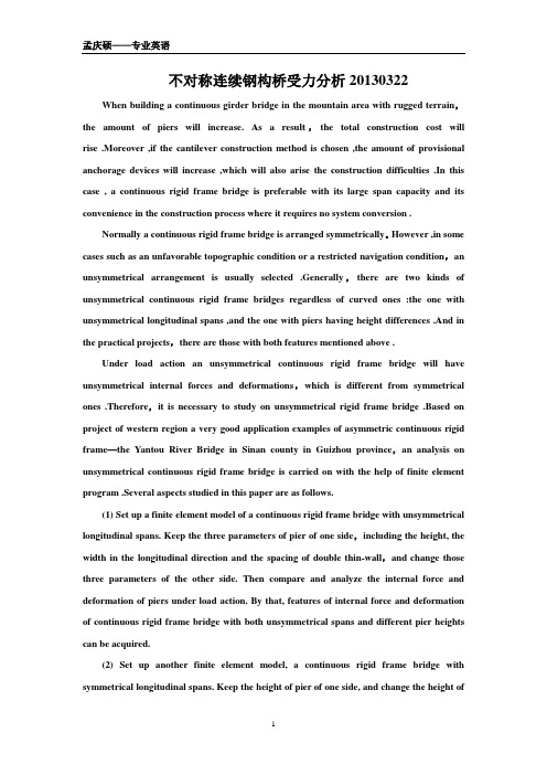
不对称连续钢构桥受力分析20130322 When building a continuous girder bridge in the mountain area with rugged terrain,the amount of piers will increase. As a result,the total construction cost will rise .Moreover ,if the cantilever construction method is chosen ,the amount of provisional anchorage devices will increase ,which will also arise the construction difficulties .In this case , a continuous rigid frame bridge is preferable with its large span capacity and its convenience in the construction process where it requires no system conversion .Normally a continuous rigid frame bridge is arranged symmetrically。
However ,in some cases such as an unfavorable topographic condition or a restricted navigation condition,an unsymmetrical arrangement is usually selected .Generally,there are two kinds of unsymmetrical continuous rigid frame bridges regardless of curved ones :the one with unsymmetrical longitudinal spans ,and the one with piers having height differences .And in the practical projects,there are those with both features mentioned above .Under load action an unsymmetrical continuous rigid frame bridge will have unsymmetrical internal forces and deformations,which is different from symmetrical ones .Therefore,it is necessary to study on unsymmetrical rigid frame bridge .Based on project of western region a very good application examples of asymmetric continuous rigid frame—the Yantou River Bridge in Sinan county in Guizhou province,an analysis on unsymmetrical continuous rigid frame bridge is carried on with the help of finite element program .Several aspects studied in this paper are as follows.(1) Set up a finite element model of a continuous rigid frame bridge with unsymmetrical longitudinal spans. Keep the three parameters of pier of one side,including the height, the width in the longitudinal direction and the spacing of double thin-wall,and change those three parameters of the other side. Then compare and analyze the internal force and deformation of piers under load action. By that, features of internal force and deformation of continuous rigid frame bridge with both unsymmetrical spans and different pier heights can be acquired.(2) Set up another finite element model, a continuous rigid frame bridge with symmetrical longitudinal spans. Keep the height of pier of one side, and change the height ofpier of the other side. Then compare and analyze the internal force and deformation of piers under load action and try to find out the characteristics of internal force and deformation of continuous rigid frame bridge with symmetrical spans but different pier heights.(3) By contrast and analysis of the layouts of tendons of an unsymmetrical rigid frame bridge (The Yantou River Bridge) and a symmetrical rigid frame bridge (The Second Wujiang River Bridge), draw some conclusions on their similarities and differences .Analyze the location differences of mid-span te ndon’s control section of symmetrical and unsymmetrical rigid frame bridge and find out the variation trends of mid-span tendon’s control section of unsymmetrical rigid frame bridge.桥梁大体积混凝土结构温度应力及其敏感性因素分析20130308With the rapidly expanding of our country transportation,the capacity of bridge design and construction technology by leaps and bounds,lots of massive bridge concrete structures have been made. But also many problems appear. One obvious problem is that as a result of big-size and complexity of the structure, the temperature stress surpasses the limits frequently,the temperature cracks come along.The temperature stress as well as the resultant stress cracks are the factors which must been considered in the designing. In the new code for design of highway bridges and culverts which has been further stressed,it tells us the factor can not be neglected in the project. Although engineers have become aware of this problem,and many specialists have also done a lot of studies,but some problems are still there,we need do more still.The paper pays more attention to the analysis suited to bridge structure for the difference between massive concrete bridge structure and the general structure.Firstly the status of the research on the mass concrete and its related theory is simply described in the paper,although not much,but it has layed the necessary theoretical basis.In the Chapter IV,some research about the temperature stress of the massive concrete structures and its related factors is done. In this paper,only a few key aspects of the analysis have been studied,for example,the relationship between the rate of water flow and cooling efficiency the depth effect of outside temperature,the effect of structure size on the stressdistribution,as well as simplification of the boundary conditions. Every aspect is derived with theoretical deduction and finite element method,and more analysis is made for the bridge structure so as to get the conclusions used for the structure of massive concrete.斜拉桥大吨位曲线混凝土箱梁在拖拉施工中的控制20130315The main bridge of railway separated interchange on Jing-xin Highway is a single tower and single cable Plane cable-stayed bridge with five spans curved prestressed continue concrete beam. It is a tower and pier consolidation system, and the girder is supported by the tower and pier. This bridge connected Jing-Bao railway,13th urban railway and Jing-Zhang Inter-city railway. There are many technical difficulties and challenge in the construction of this bridge which are either rare or unprecedented in the construction practices both domestic and abroad. Take this bridge as the engineering background,this paper analyzed the hualing process,details are as follows:(l)The hualing construction of large- tonnage curve concrete box girder . Pushing and hualing construction is one common method in bridge construction .But it is rarely used for large- tonnage curves for concrete box girder. The hualing girder section has a horizontal elevation radius of 3500m,cross slope of bridge deck change dramatically ;besides,the elevation radius is 11000m. The conditions of spanning over railways increase the difficulties of construction .To ensure that the beam would be moved along within the drag track,and prevent great lateral displacement ,ensure structural safety during the hualing,accurate and reliable theoretical calculation and strict construction control measures are needed .This paper used finite element analyzed the drag construction of main beam.(2)The hualing construction control and structural stress monitoring .The real-time monitoring of the stress of girder and temporary pier during hualing process is commenced ;the results are compared with the theoretical solution .The accuracy and the speed of corrective are improved and safety of structure is guaranteed ;besides,the effect of correction is proven by this method .Given consideration to the large distance and great amount of monitoring points ,some specific points need extra -long time of monitoring ,girder and temporary pier need real — time monitoring ;the FBG sensors areintroduced in the stress monitoring during hualing process.(3)Several key issues in hualing construction are studied and investigated .After the comparative analysis of theoretical values and actual values ,reasonable analysis and solutions are proposed in this paper .The conclusion and experience in this paper could provide reference and guidance for the design and construction of similar bridge.。
桥梁工程英语词汇

结构控制structural controlstructure control结构控制: structural control結構控制: structural control结构控制剂: constitution controller裂缝宽度容许值裂缝宽度容许值: allowable value of crack width装配式预制装配式预制: precast装配式预制的: precast-segmental装配式预制混凝土环: precast concrete segmental ring安装预应力安装预应力: prestressed最优化optimization最优化: Optimum Theory|optimization|ALARA 使最优化: optimized次最优化: suboptimization空心板梁空心板梁: hollow slab beam主梁截面主梁截面: girder section边、中跨径边、中跨径: side span &middle spin主梁girder主梁: girder|main beam|king post 桥主梁: bridge girder主梁翼: main spar单墩单墩: single pier单墩尾水管: single-pier draught tube单墩肘形尾水管: one-pier elbow draught tube结构优化设计结构优化设计: optimal structure designing扩结构优化设计: Optimal Struc ture Designing 液压机结构优化设计软件包: HYSOP连续多跨多跨连续梁: continuous beam on many supports拼接板splice barsplice plate拼接板: splice bar|scab|splice plate 端头拼接板: end matched lumber销钉拼接板: pin splice裂缝crack crevice跨越to step acrossstep over跨越: stride leap|across|spanning跨越杆: cross-over pole|crossingpole 跨越点: crossing point|crossover point刚构桥rigid frame bridge刚构桥: rigid frame bridge形刚构桥: T-shaped rigid frame bridge连续刚构桥: continuous rigid frame bridge刚度比stiffness ratioratio of rigidity刚度比: ratio of rigidity|stiffness ratio 动刚度比: dynamic stiffenss ratio刚度比劲度比: stiffnessratio等截面粱uniform beam等截面粱: uniform beam|uniform cross-section beam桥梁工程bridge constructionbridgework桥梁工程: bridgeworks|LUSAS FEA|Bridge Engineering 桥梁工程师: Bridge SE铁路桥梁工程: railway bridge engineering悬索桥suspension bridge悬索桥: suspension bridge|su e io ridge 懸索橋: Suspension bridge|Puente colgante 加劲悬索桥: stiffenedsuspensionbridge预应力混凝土prestressed concrete预应力混凝土: prestressed concrete|prestre edconcrete 预应力混凝土梁: prestressed concrete beam预应力混凝土管: prestressed concrete pipe预应力钢筋束预应力钢筋束: pre-stressing tendon|pre-stre ingtendon 抛物线型钢丝束(预应力配钢筋结构用): parabolic cable最小配筋率minimum steel ratio轴向拉力axial tensionaxial tensile force轴向拉力: axial tension|axial te ion 轴向拉力, 轴向拉伸: axial tension轴向拉力轴向张力: axialtensileforce承台cushion cap承台: bearing platform|cushioncap|pile caps 桩承台: pile cap|platformonpiles低桩承台: low pile cap拱桥arch bridge拱桥: hump bridge|arch bridge|arched bridge 拱橋: Arch bridge|Puente en arco|Pont en arc 鸠拱桥: Khājū强度intensitystrength强度: intensity|Strength|Density刚强度: stiffness|stiffne|westbank stiffness 光强度: light intensity|intensity箍筋hooping箍筋: stirrup|reinforcement stirrup|hooping 箍筋柱: tied column|hooped column形箍筋: u stirrup u预应力元件预应力元件: prestressed element等效荷载equivalent load等效荷载: equivalent load等效荷载原理: principle of equivalent loads 等效负载等效荷载等值负载: equivalentload模型matrix model mould pattern承载能力极限状态承载能力极限状态: ultimate limit states正常使用极限状态serviceability limit state正常使用极限状态: serviceability limit state正常使用极限状态验证: verification of serviceability limit states弹性elasticityspringinessspringgiveflexibility弹性: elasticity|Flexibility|stretch 彈性: Elastic|Elasticidad|弾性弹性体: elastomer|elastic body|SPUA平截面假定plane cross-section assumption平截面假定: plane cross-section assumption抗拉强度intensity of tension tensile strength安全系数safety factor标准值standard value标准值: standard value,|reference value作用标准值: characteristic value of an action 重力标准值: gravity standard设计值value of calculationdesign value设计值: design value|value|designed value 作用设计值: design value of an action荷载设计值: design value of a load可靠度confidence levelreliabilityfiduciary level可靠度: Reliability|degree of reliability 不可靠度: Unreliability高可靠度: High Reliability几何特征geometrical characteristic几何特征: geometrical characteristic配位几何特征: coordinated geometric feature 流域几何特征: basin geometric characteristics塑性plastic nature plasticity应力图stress diagram应力图: stress diagram|stress pattern 谷式应力图: Cremona's method机身应力图: fuselage stress diagram压应力crushing stress压应力: compressive stress|compression stress 抗压应力: compressive stress|pressure load内压应力: internal pressure stress配筋率ratio of reinforcement reinforcement ratioreinforcement percentage配筋率: reinforcement ratio平均配筋率: balanced steel ratio纵向配筋率: longitudinal steel ratio有限元分析finite element analysis有限元分析: FEA|finite element analysis (FEA)|ABAQUS 反有限元分析: inverse finite element analysis有限元分析软件: HKS ABAQUS|MSC/NASTRAN MSC/NASTRAN有限元法finite element method有限元法: FInite Element|finite element method 积有限元法: CVFEM线性有限元法: Linear Finite Element Method裂缝控制裂缝控制: crack control控制裂缝钢筋: crack-control reinforcement检查,核对,抑制,控制,试验,裂缝,支票,账单,牌号,名牌: check应力集中stress concentration应力集中: stress concentration应力集中点: hard spot|focal point of stress 应力集中器: stress concentrators主拉应力principal tensile stress主拉应力: principal tensile stress非线性nonlinearity非线性振动nonlinear oscillationsnonlinear vibration非线性振动: nonlinear vibration非线性振动理论: theory of non linear vibration 非线性随机振动: Nonlinear random vibration弯矩flexural momentment of flexion (moment of flexure) bending momentflexural torque弯矩: bending moment|flexural moment|kN-m 弯矩图: bending moment diagram|moment curve 双弯矩: bimoment弯矩中心center of momentsmoment center弯矩中心: center of moments|momentcenter弯矩分配法moment distributionmomentdistribution弯矩分配法: hardy cross method|cross method弯矩图bending moment diagrammoment curvemoment diagram弯矩图: bending moment diagram|moment curve 最终弯矩图: final bending moment diagram最大弯矩图: maximum bending moment diagram剪力shearing force剪力: shearing force|shear force|shear剪力墙: shear wall|shearing wall|shear panel 剪力钉: shear nails|SHEAR CONCRETE STUD弹性模量elasticity modulus young's modulus elastic modulus modulus of elasticity elastic ratio剪力图shear diagram剪力图: shear diagram|shearing force diagram剪力和弯矩图: Shear and Moment Diagrams绘制剪力和弯矩图的图解法: Graphical Method for Constructing Shear and Moment Diagrams剪力墙shear wall剪力墙: shear wall|shearing wall|shear panel 抗剪力墙: shearwall剪力墙结构: shear wall structure轴力轴力: shaft force|axial force螺栓轴力测试仪: Bolt shaft force tester 轴向力: axial force|normal force|beam框架结构frame construction等参单元等参数单元等参元: isoparametricelement板单元板单元: plate unit托板单元: pallet unit骨板骨单元: lamella/lamellaeosteon梁(surname) beam of roof bridge桥梁bridge曲率curvature材料力学mechanics of materials结构力学structural mechanics结构力学: Structural Mechanics|theory of structures 重结构力学: barodynamics船舶结构力学: Structual Mechamics for Ships弯曲刚度flexural rigiditybending rigidity弯曲刚度: bending stiffness|flexural rigidity 截面弯曲刚度: flexural rigidity of section弯曲刚度,抗弯劲度: bending stiffness钢管混凝土结构encased structures钢管混凝土结构: encased structures极限荷载ultimate load极限荷载: ultimate load极限荷载设计: limit load design|ultimate load design 设计极限荷载: designlimitloadDLL|design ultimate load极限荷载设计limit load designultimate load analysisultimate load design极限荷载设计: limit load design|ultimate load design 设计极限荷载: designlimitloadDLL|design ultimate load板壳力学mechanics of board shell板壳力学: Plate Mechanics板壳非线性力学: Nonlinear Mechanics of Plate and Shell本构模型本构模型: constitutive model体积本构模型: bulk constitutive equation 本构模型屈服面: yield surface主钢筋main reinforcing steelmain reinforcement主钢筋: main reinforcement|Main Reinforcing Steel 钢筋混凝土的主钢筋: mainbar悬臂梁socle beam悬臂梁: cantilever beam|cantilever|outrigger 悬臂梁长: length of cantilever双悬臂梁: TDCB悬链线catenary悬链线: Catenary,|catenary wire|chainette 伪悬链线: pseudocatenary悬链线长: catenary length加劲肋ribbed stiffener加劲肋: stiffening rib|stiffener|ribbed stiffener 短加劲肋: short stiffener支承加劲肋: bearing stiffener技术标准technology standard水文水文: Hydrology水文学: hydrology|hydroaraphy|すいもんがく水文图: hydrograph|hydrological maps招标invite public bidding投标(v) submit a bid bid for连续梁through beam连续梁: continuous beam|through beam多跨连续梁: continuous beam on many supports 悬臂连续梁: gerber beam加劲梁stiff girder加劲梁: stiffening girder|buttress brace 加劲梁节点: stiff girder connection支撑刚性梁,加劲梁,横撑: buttress brace水文学hydrology水文学: hydrology|hydroaraphy|すいもんがく水文學: Hydrologie|水文学|??? ??????古水文学: paleohydrology桥梁抗震桥梁抗震加固: bridge aseismatic strengthening抗风wind resistance抗风: Withstand Wind|Wtstan Wn|wind resistance 抗风锚: weather anchor抗风性: wind resistance基础的basal桥梁控制测量bridge construction control survey桥梁控制测量: bridge construction control survey桥梁施工桥梁施工控制综合程序系统: FWD桥梁最佳施工指南: Bridge Best Practice Guidelines桥梁工程施工技术咨询: Bridge Construction Engineering Service总体设计overall designintegrated design总体设计: Global|overall design|general arrangement 总体设计概念: totaldesignconcept工厂总体设计图: general layout scheme初步设计predesign preliminary plan技术设计technical design技术设计: technical design|technical project 技术设计员: Technical Designer|technician技术设计图: technical drawing施工图设计construction documents design施工图设计: construction documents design施工图设计阶段: construction documents design phase基本建设项目施工图设计: design of working drawing of a capital construction project桥台abutment bridge abutment基础foundation basebasis结构形式structural style结构形式: Type of construction|form of structure 表结构形式: list structure form屋顶结构形式: roof form地震earthquake地震活动earthquake activityseismic activityseismic motionseismicity地震活动: Seismic activity|seismic motion 地震活动性: seismicity|seismic地震活动图: seismicity map支撑体系支撑体系: bracing system|support system 物流企业安全平台支撑体系: SSOSP公路桥涵公路施工手册-桥涵: Optimization of Road Traffic Organization-Abstract引道approach roadramp wayapproach引道: approach|approach road引道坡: approach ramp|a roachramp 引道版: Approach slab装配式装配式桥: fabricated bridge|precast bridge 装配式房屋: Prefabricated buildings装配式钢体: fabricated steel body耐久性wear耐久性: durability|permanence|endurance不耐久性: fugitiveness耐久性试验: endurance test|life test|durability test持久状况持久状况: persistent situation 短暂状况短暂状况: transient situation 偶然状况偶然状况: accidental situation永久作用永久作用: permanent action永久作用标准值: characteristic value of permanent action可变作用可变作用: variable action可变作用标准值: characteristic value of variable action 可变光阑作用: iris action偶然作用偶然作用: accidental action偶然同化(作用): accidental assimilation作用效应偶然组合: accidental combination for action effects作用代表值作用代表值: representative value of an action作用标准值作用标准值: characteristic value of an action地震作用标准值: characteristic value of earthquake action 可变作用标准值: characteristic value of variable action作用频遇值作用频遇值 Frequent value of an action安全等级safe class安全等级: safety class|Security Level|safeclass 生物安全等级: Biosafety Level生物安全等級: Biosafety Level作用actionactivity actionsactseffectto play a role设计基准期design reference period设计基准期: design reference period作用准永久值作用准永久值: quasi-permanentvalueofanaction作用效应作用效应: effects of actions|effect of an action 互作用效应: interaction effect质量作用效应: mass action effect作用效应设计值作用效应设计值 Design value of an action effect分项系数分项系数: partial safety factor|partial factor作用分项系数: partial safety factor for action抗力分项系数: partial safety factor for resistance作用效应组合作用效应组合: combination for action effects作用效应基本组合: fundamental combination for action effects 作用效应偶然组合: accidental combination for action effects结构重要性系数结构重要性系数Coefficient for importance of a structure桥涵桥涵跟桥梁比较类似,主要区别在于:单孔跨径小于5m或多孔跨径之和小于8m的为桥涵,大于这个标准的为桥梁公路等级公路等级: highway classification标准:公路等级代码: Code for highway classification标准:公路路面等级与面层类型代码: Code for classification and type of highway pavement顺流fair current设计洪水频率设计洪水频率: designed flood frequency水力water powerwater conservancyirrigation works水力: hydraulic power|water power|water stress水力学: Hydraulics|hydromechanics|fluid mechanics 水力的: hydraulic|hydrodynamic|hyd河槽river channel河槽: stream channel|river channel|gutter 古河槽: old channel河槽线: channel axis河岸riversidestrand河岸: bank|riverside|river bank 河岸林: riparian forest河岸权: riparian right河岸侵蚀stream bank erosion河岸侵蚀: bank erosion|stream bank erosion 河岸侵蚀河岸侵食: bank erosion河岸侵蚀, 堤岸冲刷: bank erosion高架桥桥墩高架桥桥墩: viaduct pier桥梁净空高潮时桥梁净空高度: bridge clearance行车道lane行车道: carriageway|traffic lane|Through Lane 快行车道: fast lane西行车道: westbound carriageway一级公路A roadarterial roadarterial highway一级公路: A road arterial road arterial highway 一级公路网: primaryhighwaysystem二级公路b roadsecondary road二级公路: B road, secondary road涵洞culvert涵洞: culvert梁涵洞: Beam Culverts 木涵洞: timber culvert河床riverbedrunway河床: river bed|bed|stream bed冰河床: glacier bed型河床: oxbow|horseshoe bend|meander loop河滩flood plainriver beach河滩: river shoal|beach|river flat 河滩地: flood land|overflow land 河滩区: riffle area高级公路high-type highway高级公路: high-typehighway高架桥trestleviaduct高架桥: viaduct|overhead viaduct 高架橋: Viadukt|Viaducto|高架橋高架桥面: elevated deck洪水流量volume of floodflood dischargeflooddischarge洪水流量: flood discharge|flood flow|peak discharge 洪水流量预报: flooddischargeforecast平均年洪水流量: average annual flood设计速度design speed设计速度: design speed|designed speed|design rate设计速度,构造速度: desin speed|desin speed <haha最大阵风强度的设计速度: VB Design Speed for Maximum Gust Intension跨度span紧急停车emergency shutdown (cut-off)emergency cut-off紧急停车: abort|panic stop|emergency stop 紧急停车带: lay-by|emergency parking strip 紧急停车阀: emergency stop valve减速gear downretardment speed-down deceleration slowdown车道traffic lane路缘带side tripmarginal stripmargin verge路缘带: marginal strip|side strip|margin verge路肩shoulder of earth body路肩: shoulder|verge|shoulder of road 硬路肩: hard shoulder|hardened verge 软路肩: Soft Shoulder最小值minimum value最小值: minimum|Min|least value 求最小值: minimization找出最小值: min最大值max.最大值原理principle of the maximummaximum principlemaximal principle最大值原理: maximum principle,|maximal principle 离散最大值原理: discrete maximum principle极大值原理,最大值原理: maximum principle车道宽度车道宽度: lane-width自行车道cycle-track自行车道: bicycle path|cycle path|cycle track旗津环岛海景观光自行车道: Cijin Oceanview Bike Path 自行车道专供自行车行驶的车道。
路桥工程专业英语第六课

第六课:Bridge Introduction桥梁概论Text: BridgesRead Material: Bridge Design ConceptTextBridgesA bridge is a structure providing passage over an obstacle such as a vally, road, railway, canal, river, without closing the way beneath. The required passage may be for road, railway, cannal, pipeline, cycle track or pedestrains.The branch of civil engineering which deals with the design, planning construction and maintenance of bridge is known as bridge engineering.1 Components of a bridgeFigure 14-1a) shows the elevation while Fig. 14-1b) presents the plan of a bridge.Broadly, a bridge can be divided into two major parts: superstructure and substructure. The superstructure of a bridge is analogous to a single storey building roof and substructure to that of the walls, columns and foundations supporting it.Superstructure consists of structural menbers carrying a communication route. Thus hanrails, guardstones and flooring supported by any structural system, such as beams, girders, arches and cables, above the level of bearings form the superstructure.Substructure is a supporting system for the superstructure. It consists of piers, abutments, wingwalls and foundations for the piers and abutments.The other main parts of a bridge structure are the approaches, bearings and river training works, such as the aprons, and the rivetment for slopes at abutments, etc. Some of the important components of a bridge are explained in this section.Piers: These are provided in between the two extreme supports of the bridge (abutments) and in the bed of the river to reduce the span and share the total load coming over the bridge. Piers are provided with foundation which is taken below the bed of the river where hard soil is available.Abutments: The end supports of a bridge superstructure are called abutments. It may be of brick masonry, stone masonry, R.C. or precast concrete block. It serves both as a pier and as a retaining wall. The height of a abutment is equal to that of the piers. The functions of an abutmentare the following:(1) To transmit the load from the bridge superstructure to the foundations.(2) To give final formation level to the bridge superstructure.(3) To retain earth work of embankment of the approaches.Wing walls: The walls constructed at both end of the abutments to retain the earthfilling of bridge approaches are called wing walls. Normally, the wing walls have steadily decreasing cross section. The design of wing walls is independent. Generally, water face of these walls is kept vertical.Foundations: The lowest artificially built parts of piers, abutments etc. which are in direct contactwith the subsoil supporting the structure are called foundations.The factors which affect the selection of foundation include the type of soil, the nature of soil, the type of the bridge, the velocity of water and the superimposed load on the bridge.Well foundation is the most commonly adopted foundation in India. The foundation may consist of a single large diameter well or a group of smaller wells of circular or other shapes.Approaches: These are the lengths of communication route at both ends of the bridge. Approaches may be in embankment or in cutting depending upon the design of the bridge. It is recommended (as per Indian Road Congress) that the approaches must be straight for a minimum length of 16 m on either side of the bridge. Its function is to carry the communication route up to the floor level of the bridge.Hand Rails and Guard Stones: Hand rails are provided on both sides of a bridge to prevent any vehicle from falling into the stream. Footpaths are also provided for pedestrians to walk along without interfering with the heavy vehicular traffic.In order to prevent a vehicle from stricking the parapet wall or the hand rails, guard stones painted white are provided along the edge of the footpaths at the ends of the road surface. Guard stones are also provided along both sides of the approach roads in filling to prevent the vehicles from toppling over the sides of the embankments.Bearings for the Girders: The longitudinal girders have to rest over the piers which bears the thrust of the load coming over them. In order that the girder ends should rest on proper seats, the same are provided with bearing blocks made of cement concrete, so that the load may be uniformly distributed over the structure on which they rest. Due to the expansion and contraction of the longitudinal girders during severe heat and cold, rollers are provided on the abutment ends to allow the movements without causing the girder to buckle.2 Types of bridges2.1 Arch bridgeArch bridge are often used because of their pleasing appearance. These are more graceful and suited for deep gorges with rocky abutments. Arch bridges can be economically adopted up to a span of 250 m. In this type of bridge, the roadway is constructed on an arch which rests on piers and abutments. An example of an arch bridge is the rainbow bridge across Niagara river over a span of 290m.The advantages of an arch bridge are: There will be no bending anywhere in the arch, vibrations due to impact forces are minimum, and pleasing appearance.2.2 Slab bridgeThis is the simplest type of R.C. bridge and easiest to construct. Slab bridges are generally found to be economical for span up to 9 m. The thickness of slab is quite considerable but uniform, thereby requiring simple shuttering. Though the amount of concrete and steel required are more, the construction is much simpler and placement of material is easy.2.3 T-beam and slab bridgeThis consists of T-beams supported over piers and abutments. The deck slab is supported over the T-beams. This type of bridge is suitable for span between 9-20 m. T-beam bridge is cheaper and requires less quantity of materials. For example, the longest R.C. T-beam bridge in India is the Advai Bridge in Goa with a pier spacing of 35 m.2.4 Bow string girder bridgeBow string girder bridges are economical when sufficient head room is needed under a bridge. The main components here are resembling the bow and a tie beam resembling the string of the bow. As the major portion of the load will be borne by the beam, the thrust on the abutments from the arch will be limited. Hence, the abutments need not be too heavy. The roadway is actually suspended from the arch rib by means of vertical suspenders as presented in Fig. 14-2. These bridges can be adopted for spans of 30-45 m.2.5 Suspension bridgeSuperstructure of a suspension bridge consists of two sets of cables over the towers,carrying the bridge floor by means of suspenders as shown in Fig. 14-3. This bridge is best suited for light traffic for large spans exceeding 600 m . These bridges are flexible and hence the vertical oscillations will be more than the other bridges. The entire load will be borne by the cables whichare anchored to the ground.2.6 The cable-stayed bridgeCable-stayed bridges are constructed along a structural system which comprises an orthotropic deck and continuousgirders which are supported by stays, i.e. inclined cables passing over or attached to towers located at the main piers. Modern cable-stayed bridges present a three-dimensional system consisting of stiffening girders, transverse and longitudinal bracing , orthotropic-type deck and supporting parts such as towers in compression and inclined cables in tension, The important characteristics of such a three-dimensional structure is the full participation of the transverse construction in the work of the main longitudinal structure. This means a considerable increase in the moment of inertia of the construction which permits a reduction in the depth of the girders and economy in steel.2.7 Steel bridgesSteel bridges are commonly used for supporting highways, water, oil or gas pipes, a railway track, etc. They can be classified as follows:2.7.1 Steel Truss bridgesSteel truss bridges are provided for long railway bridges, as they are less affected by wind pressure. It is easy to erect steel truss bridges since its component members are relatively light in weight. The primary forces in its members are axial forces. Steel truss bridges which are commonly used are the following.2.7.2 Steel Rigid Frame BridgeThese type of bridges, carry the roadway at the top of the portal frames. No bearing and fixtures are required in such bridges. These bridges have more clearance below them and heavy abutments are not required.2.7.3 Plate Girder BridgesA plate girder bridge is used to carry heavier loads over longer spans. Hence, they are mainly used for railway bridges. These are used for spans up to 20 m. In order to increase the lateral stability, box girder which consists of four plates connected by angles are used.2.7.4 Steel Arch BridgesSteel arch bridges are constructed where it is not possible to construct intermediate pier. It can be used for a very long span , i.e. up to 150 m . Steel arches may either be of the spandrelbraced or trussed arch type as shown in Fig. 14-4.2.7.5 Steel Bow String Girder BridgesIn steel bow string girder bridges, in order to bear horizontal thrust, a steel tie is provided which joins the two ends of an arch. In these bridges, suspenders are provided from the arch-ribs to carry the roadway.Words and Expressionspassage:通道;Obstacle:障碍;Closing:封闭;Beneath:在……之下;Pipeline:管线;cycle track:自行车道;Pedestrain:徒步的,行人;Elevation:高程、海拔,正视图;Superstructure:上部结构;Substructure:下部结构;Analogous:类似的;be analogous to 类似;Storey:层;Foundation:基础;Thus:如此、像这样、如下,于是;Hanrail:护栏;Guardstone:护石;Beam:梁;Girder(大)梁;Arch:拱;Cable:缆索;Bearing:支座;Pier:桥墩;Abutment:桥台、拱座;Wingwall:翼墙;Approach:引道、引桥;Apron:围裙;rivetment:锚固、铆钉;Support:支承;provide with:提供、装备、供给;Masonry:砌体;Precast:预制的、预浇筑的;retaining wall:护壁、挡墙;Transmit:传递;Formation:构成、队形;earth work:土压力;Artificially:人工地、人造地;Contact:接触;Subsoil:底土、天然地基;Velocity:速度;Superimpose:把…放在另一物上面,加上;Well:井;up to:直到;Footpath:人行道;Interfere:干涉、妨碍;Vehicular:车辆的、车载的;Parapet:护墙、女儿墙;topple over:倒塌、倒下;Longitudinal:纵向的;thrust:插、刺、戳,推力;the same:相同的、同样的;Uniformly:一致的、一样的;Contraction:收缩、缩短;severe:严肃的、剧烈的;Roller:滚筒、辊子;Buckle:弯曲;Arch bridge:拱桥;Gorge:峡谷;Bend:弯曲;Vibration:振动、颤动、摆动;Slab bridge:板桥;Considerable:值得注意的、相当大的;Shuttering:模板;T-beam:T梁;deck:甲板、桥面;Quantity:量、数额;Bow:弓、虹;Bow string girder :系杆拱桥;resemble:像、类似;tie beam:系梁;String:线,一串,弦;Borne:bear的过去分词,出身于,天生的;Rib:肋骨、拱肋;Suspenders:吊杆;by means of:依靠;Suspension:悬吊、悬浮;Oscillation:振动、振幅;Anchor:锚固、抛锚,桩;Cable-stayed bridges:斜拉桥;comprise:包含、由…组成;Orthotropic:正交的,Stay:支柱、支撑物;Stiffen:硬化、加强;Transverse:横向,横切的;Bracing:使拉紧的、支柱;Orthotropic:支架桥面合一的;compression :压力;Tension:拉力;Participation:关系、参与、合作、分享;Moment:矩;inertia:惯性、惯量;moment of inertia:惯性矩;Reduction:减少;classify:分类;truss:桁架;Erect:架设;Rigid:坚硬的、刚性的;Frame:构架;Rigid Frame Bridge:刚架桥;portal :入口、门;portal frame:门架;Clearance:净空;Plate:板、用板加固,镀;lateral:侧向的;Angle:角;Intermediate:中间的、居间的;spandrel :拱肩、拱上建筑;Brace:支撑、张、拉紧;。
土木工程专业英语(桥梁)
原始桥梁的第一步变革被认为出现在中国古 随后传入印度。河床一般比树要宽, 代,随后传入印度。河床一般比树要宽,中 国人和印度人从河的两岸到河中央用两堆树 干来建造。 干来建造。
In each arm of the structure, the logs were piled on top of one another with a slight upward slant, with each layer projected several feet beyond the one immediately below it. For stability, each pile of timbers was anchored by a massive pile of stone on each bank. Near midstream , the gap between the ends of the arms was closed by the addition of a simple beam between the two ends. 每个分支中, 每个分支中 , 圆木一个接一个的布置并微微向上 倾斜,使其每一层都比它下面的高几英尺。 倾斜,使其每一层都比它下面的高几英尺。为了 增加稳定性, 增加稳定性,每个木桩在两岸都用一堆大而重的 石头锚固;接近河中央, 石头锚固;接近河中央,在河中间的两个分支的 两端则用简支梁连接。 两端则用简支梁连接。
stout结实的;厚实的 结实的; 结实的
在森林里,随处可得结实的木材, 在森林里,随处可得结实的木材,那时侯的桥极 可能是由并排的几根圆木建成, 可能是由并排的几根圆木建成,可能在其上覆 一些木枝或草垫以方便行走。 一些木枝或草垫以方便行走。