数字滤波器文献翻译
IIR数字滤波器的设计外文文献以与翻译

IIRDigitaFilterDesignAn important step in the development of a digital filter is the determination of a realizable transfer function G(z) approximating the given frequency response specifications. If an IIR filter is desired,it is also necessary to ensure that G(z) is stable. The process of deriving the transfer function G(z) is called digital filter design. After G(z) has been obtained, the next step is to realize it in the form of a suitable filter structure. In chapter 8,we outlined a variety of basic structures for the realization of FIR and IIR transfer functions. In this chapter,we consider the IIR digital filter design problem. The design of FIR digital filters is treated in chapter 10.First we review some of the issues associated with the filter design problem. A widely used approach to IIR filter design based on the conversion of a prototype analog transfer function to a digital transfer function is discussed next. Typical design examples are included to illustrate this approach. We then consider the transformation of one type of IIR filter transfer function into another type, which is achieved by replacing the complex variable z by a function of z. Four commonly used transformations are summarized. Finally we consider the computer-aided design of IIR digital filter. To this end, we restrict our discussion to the use of matlab in determining the transfer functions.9.1 preliminary considerationsThere are two major issues that need to be answered before one can develop the digital transfer function G(z). The first and foremost issue is the development of a reasonable filter frequency response specification from the requirements of the overall system in which the digital filter is to be employed. The second issue is to determine whether an FIR or IIR digital filter is to be designed. In the section ,we examine these two issues first .Next we review the basic analytical approach to the design of IIR digital filters and then consider the determination of the filter order that meets the prescribed specifications. We also discuss appropriate scaling of the transfer function.9.1.1 Digital Filter SpecificationsAs in the case of the analog filter,either the magnitude and/or the phase(delay) response is specified for the design of a digital filter for most applications. In some situations, the unit sample response or step response may be specified. In most practical applications, the problem of interest is the development of a realizable approximation to a given magnitude response specification. As indicated in section 4.6.3, the phase response of the designed filter can be corrected by cascading it with an allpass section. The design of allpass phase equalizers has received a fair amount of attention in the last few years. We restrict our attention in this chapter to the magnitude approximation problem only. We pointed out in section 4.4.1 that there are four basic types of filters,whose magnitude responses are shown in Figure 4.10. Since the impulse response corresponding to each of these is noncausal and of infinite length, these ideal filters are not realizable. One way of developing a realizable approximation to these filter would be to truncate the impulse response as indicated in Eq.(4.72) for a lowpass filter. The magnitude response of the FIR lowpass filter obtained by truncating the impulse response of the ideal lowpass filter does not have a sharp transition from passband to stopband but, rather, exhibits a gradual "roll-off."Thus, as in the case of the analog filter design problem outlined in section 5.4.1, the magnitude response specifications of a digital filter in the passband and in the stopband are given with some acceptable tolerances. In addition, a transition band is specified between the passband and the stopband to permit the magnitude to drop off smoothly. For example, the magnitude )(j e G of a lowpass filter may be given as shown in Figure7.1. As indicated in the figure, in the passband defined by 0p ωω≤≤, we require that the magnitude approximates unity with an error of p δ±,i.e.,p p j p for e G ωωδδω≤+≤≤-,1)(1.In the stopband, defined by πωω≤≤s ,we require that the magnitude approximates zero with an error of i s ,δ.e.,,)(s j e G δω≤ forπωω≤≤s . The frequencies p ω and s ω are , respectively, called the passband edge frequency and the stopband edge frequency. The limits of the tolerances in the passband and stopband, p δ and s δ, are usually called the peak ripple values. Note that the frequency response )(ωj e G of a digital filter is a periodic function of ω,and the magnitude response of a real-coefficient digital filter is an even function ofω. As a result, the digital filter specifications are given only for the range πω≤≤0.Digital filter specifications are often given in terms of the loss function,)(log 20)(10ωωζj e G -=, in dB. Here the peak passband ripplep α and the minimum stopband attenuations α are given in dB,i.e., the loss specifications of a digitalfilter are given bydB p p )1(log 2010δα--=,dB s s )(log 2010δα-=.9.1 Preliminary ConsiderationsAs in the case of an analog lowpass filter, the specifications for a digital lowpass filter may alternatively be given in terms of its magnitude response, as in Figure 7.2. Here the maximum value of the magnitude in the passband is assumed to be unity, and themaximum passband deviation, denoted as 1/21ε+,is given by the minimum value of the magnitude in the passband. The maximum stopband magnitude is denoted by 1/A.For the normalized specification, the maximum value of the gain function or the minimum value of the loss function is therefore 0 dB. The quantity max α given bydB )1(log 20210max εα+=Is called the maximum passband attenuation. Forp δ<<1, as is typically the case, itcan be shown thatp p αδα2)21(log 2010max ≅--≅ The passband and stopband edge frequencies, in most applications, are specified in Hz, along with the sampling rate of the digital filter. Since all filter design techniques are developed in terms of normalized angular frequencies p ω and s ω,the sepcified critical frequencies need to be normalized before a specific filter design algorithm can be applied. Let T F denote the sampling frequency in Hz, and F P and F s denote, respectively,the passband and stopband edge frequencies in Hz. Then the normalized angular edge frequencies in radians are given byT F F F F p TpT p p ππω22==Ω= T F F F F s T s T s s ππω22==Ω= 9.1.2 Selection of the Filter TypeThe second issue of interest is the selection of the digital filter type,i.e.,whether an IIR or an FIR digital filter is to be employed. The objective of digital filter design is to develop a causal transfer function H(z) meeting the frequency response specifications. For IIR digital filter design, the IIR transfer function is a real rational function of 1-z . H(z)=N MdNzz d z d d pMz z p z p p ------++++++++ (2211022110)Moreover, H(z) must be a stable transfer function, and for reduced computational complexity, it must be of lowest order N. On the other hand, for FIR filter design, the FIR transfer function is a polynomial in 1-z:∑=-=Nnnz nhzH] [)(For reduced computational complexity, the degree N of H(z) must be as small as possible.In addition, if a linear phase is desired, then the FIR filter coefficients must satisfy the constraint:][][Nnhnh-±=T here are several advantages in using an FIR filter, since it can be designed with exact linear phase and the filter structure is always stable with quantized filter coefficients. However, in most cases, the order N FIR of an FIR filter is considerably higher than the order N IIR of an equivalent IIR filter meeting the same magnitude specifications. In general, the implementation of the FIR filter requires approximately N FIR multiplications per output sample, whereas the IIR filter requires 2N IIR+1 multiplications per output sample. In the former case, if the FIR filter is designed with a linear phase, then the number of multiplications per output sample reduces to approximately (N FIR+1)/2. Likewise, most IIR filter designs result in transfer functions with zeros on the unit circle,and the cascade realization of an IIR filter of orderIIRN with all of the zeros on the unitcircle requires [(3IIRN+3)/2] multiplications per output sample. It has been shown that for most practical filter specifications, the ratio N FIR/N IIR is typically of the order of tens or more and, as a result, the IIR filter usually is computationally more efficient[Rab75]. However ,if the group delay of the IIR filter is equalized by cascading it with an allpass equalizer, then the savings in computation may no longer be that significant [Rab75]. In many applications, the linearity of the phase response of the digital filter is not an issue,making the IIR filter preferable because of the lower computational requirements.9.1.3 Basic Approaches to Digital Filter DesignIn the case of IIR filter design, the most common practice is to convert the digital filter specifications into analog lowpass prototype filter specifications, and then to transform it into the desired digital filter transfer function G(z). This approach has been widely used for many reasons:(a) Analog approximation techniques are highly advanced.(b) They usually yield closed-form solutions.(c) Extensive tables are available for analog filter design.(d) Many applications require the digital simulation of analog filters.In the sequel, we denote an analog transfer function as)()()(s D s P s H a a a =, Where the subscript "a" specifically indicates the analog domain. The digital transfer function derived form H a (s) is denoted by)()()(z D z P z G = The basic idea behind the conversion of an analog prototype transfer function H a (s) into a digital IIR transfer function G(z) is to apply a mapping from the s-domain to the z-domain so that the essential properties of the analog frequency response are preserved. The implies that the mapping function should be such that(a) The imaginary(j Ω) axis in the s-plane be mapped onto the circle of the z-plane.(b) A stable analog transfer function be transformed into a stable digital transfer function.To this end,the most widely used transformation is the bilinear transformation described in Section 9.2.Unlike IIR digital filter design,the FIR filter design does not have any connection with the design of analog filters. The design of FIR filter design does not have anyconnection with the design of analog filters. The design of FIR filters is therefore based on a direct approximation of the specified magnitude response,with the often added requirement that the phase response be linear. As pointed out in Eq.(7.10), a causal FIR transfer function H(z) of length N+1 is a polynomial in z -1 of degree N. The corresponding frequency response is given by∑=-=N n n j j en h e H 0][)(ωω.It has been shown in Section 3.2.1 that any finite duration sequence x[n] of length N+1 is completely characterized by N+1 samples of its discrete-time Fourier transfer X(ωj e ). As a result, the design of an FIR filter of length N+1 may be accomplished by finding either the impulse response sequence {h[n]} or N+1 samples of its frequency response )H(e j ω. Also, to ensure a linear-phase design, the condition of Eq.(7.11) must be satisfied. Two direct approaches to the design of FIR filters are the windowed Fourier series approach and the frequency sampling approach. We describe the former approach in Section 7.6. The second approach is treated in Problem 7.6. In Section 7.7 we outline computer-based digital filter design methods.作者:Sanjit K.Mitra国籍:USA出处:Digital Signal Processing -A Computer-Based Approach 3eIIR数字滤波器的设计在一个数字滤波器发展的重要步骤是可实现的传递函数G(z)的接近给定的频率响应规格。
DSP滤波器中英文对照外文翻译文献

中英文对照外文翻译文献(文档含英文原文和中文翻译)译文:GA算法优化IIR滤波器的设计摘要本文提出了运用遗传算法(GA)来优化无限脉冲响应数字滤波器(IIR)的设计。
IIR滤波器本质上是一个递归响应的数字滤波器。
由于IIR 数字滤波器的表面误差通常是非线性的和多峰的,而全局优化技术需要避免局部最小值。
本文提出了启发式方式来设计IIR滤波器。
GA是组合优化问题中一种功能强大的全局优化算法,该论文发现IIR数字滤波器的最佳系数可以通过GA 优化。
该设计提出低通和高通IIR数字滤波器的设计,以提供过渡频带的估计值。
结果发现,所计算出的值比可用于过滤器的在MATLAB设计FDA工具更优化。
举个例子,采用的仿真结果表明在过渡带和均方误差(MSE)的改善。
零极点的位置也被提出来用来描述系统的的稳定性,以便将结果与模拟退火(SA)的方法相比较。
关键词:数字滤波器;无限冲激响应(IIR);遗传算法(GA);优化1.说明在过去的几十年中的数字信号处理(DSP)领域已经成长太重要的理论和技术。
在DSP中,有两个重要的类型系统。
第一类型的系统是执行信号滤波的时域,因此它被称为数字滤波器。
第二类型的系统提供的信号表示频域,被称为频谱分析仪。
数字滤波是DSP的最有力的工具之一。
数字滤波器能够性能规格,最好的同时也是极其困难的,而且不可能的是,先用模拟滤波器实现。
另外,数字滤波器的特性,可以很容易地在软件控制下发生变化。
数字滤波器被分类为有限持续时间脉冲响应(FIR)滤波器或无限持续时间脉冲响应(IIR)滤波器,这取决于该系统的脉冲响应的形式。
在FIR系统中,脉冲响应序列是有限的持续时间,即,它具有非零项的数量有限。
数字无限脉冲响应(IIR)滤波器通常可以提供比其等效有限脉冲响应(FIR)滤波器更好的性能和更少的计算成本,并已成为越来越感兴趣的目标。
但是,由于IIR滤波器的误差表面通常是非线性的,多式联运,传统的基于梯度的设计方法可以很容易地陷入错误的表面。
matlab滤波器外文翻译外文文献英文文献IIR数字滤波器的设计(整理)
数字滤波器的仿真与实现 - 中英文翻译

数字滤波器的仿真与实现 - 中英文翻译东南大学成贤学院毕业设计外文翻译电子工程系电子信息工程专业学生姓名:公冶允懋学号: 01408146 设计地点:东南大学成贤学院指导教师:李东新Thal filterWith the information age and the advent of the digital world, digital signal processing has become one of today's most important disciplines and door technology. Digital signal processing in communications, voice, images, automatic control, radar, military, aerospace, medical and household appliances, and many other fields widely applied. In the digital signal processing applications, the digital filter is important and has been widely applied.1、 figures Unit on : Analog and digital filtersIn signal processing, the function of a filter is to remove unwanted parts of the signal, such as random noise, or to extract useful parts of the signal, such as the components lying within a certain frequency range.The following block diagram illustrates the basic idea.There are two main kinds of filter, analog and digital. They are quite different in their physical makeup and in how they work. An analog filter uses analog electronic circuits made up from components such as resistors,capacitors and op amps to produce the required filtering effect. Such filter circuits are widely used in such applications as noise reduction, video signal enhancement, graphic equalisers in hi-fi systems, and many other areas. There are well-established standard techniques for designing an analog filtercircuit for a given requirement. At all stages, the signal being filtered isan electrical voltage or current which is the direct analogue of the physical quantity (e.g. a sound or video signal or transducer output) involved. Adigital filter uses a digital processor to perform numerical calculations on sampled values of the signal. The processor may be a general-purpose computer such as a PC, or a specialised DSP (Digital Signal Processor) chip. The analog input signal must first be sampled and digitised using an ADC (analog todigital converter). The resulting binary numbers, representing successive sampled values of the input signal, are transferred to the processor, which carries out numerical calculations on them. These calculations typicallyinvolve multiplying the input values by constants and adding the products together.If necessary, the results of these calculations, which now represent sampled values of the filtered signal, are output through a DAC (digital to analog converter) to convert the signal back to analog form.Note that in a digital filter, the signal is represented by a sequence of numbers, rather than a voltage or current.The following diagram shows the basic setup of such a system.Unit refers to the input signals used to filter hardware or software. Ifthe filter input, output signals are separated, they are bound to respond tothe impact of the Unit is separated, such as digital filters filter definition. Digital filter function, which was to import sequences X transformation into export operations through a series Y.According to figures filter function 24-hour live response characteristics, digital filters can be divided into two, namely, unlimited long live long live the corresponding IIR filter and the limited response to FIR filters. IIRfilters have the advantage of the digital filter design can use simulation results, and simulation filter design of a large number of tables mayfacilitate simple. It is the shortcomings of the nonlinear phase; Linear phaseif required, will use the entire network phase-correction. Image processingand transmission of data collection is required with linear phase filtersidentity. And FIR linear phase digital filter to achieve, but an arbitrarymargin characteristics. Impact from the digital filter response of the unitscan be divided into two broad categories : the impact of the limited response(FIR) filters, and unlimited number of shocks to (IIR) digital filters.FIR filters can be strictly linear phase, but because the system FIRfilter function extremity fixed at the original point, it can only use thehigher number of bands to achieve their high selectivity for the same filterdesign indicators FIR filter called band than a few high-IIR 5-10 times, thecost is higher, Signal delay is also larger. But if the same linear phase, IIRfilters must be network-wide calibration phase, the same section also increasethe number of filters and network complexity. FIR filters can be used toachieve non-Digui way, not in a limited precision of a shock, and into thehomes and quantitativefactors of uncertainty arising from the impact of errors than IIR filtersmall number, and FIR filter can be used FFT algorithms, the computationalspeed. But unlike IIR filter can filter through the simulation results, thereis no ready-made formula FIR filter must use computer-aided design software(such as MATLAB) to calculate. So, a broader application of FIR filters, andIIR filters are not very strict requirements on occasions.Unit from sub-functions can be divided into the following four categories :(1) Low-filter (LPF); (2) high-filter (HPF); (3) belt-filter (BPF); (4) toprevent filter (BSF).The following chart dotted line for the ideals of the filter frequencycharacteristics : A1(f) A2(f)1 10 fc2 f 0 fc2 f (a)(b) A3(f) A4(f)1 10 fc1 fc2 f 0 fc1 fc2 f (c)(d) (a)LPF (b)HPF (c)BPF (d)BSF2、 MATLAB introducedMATLAB is a matrix laboratory (Matrix Laboratory) is intended. In addition to an excellent value calculation capability, it also provides professional symbols terms, word processing, visualization modeling, simulation and real-time control functions. MATLAB as the world's top mathematical software applications, with a strong engineering computing, algorithms research, engineering drawings, applications development, data analysis and dynamic simulation, and other functions, in aerospace, mechanical manufacturing and construction fields playing an increasingly important role. And the C language function rich, the use offlexibility, high-efficiency goals procedures. High language both advantages as well as low level language features. Therefore, C language is the most widely used programming language. Although MATLAB is a complete,fully functional programming environment, but in some cases, data and procedures with the external environment of the world is very necessary and useful. Filter design using Matlab, could be adjusted with the design requirements and filter characteristics of the parameters, visual simple, greatly reducing the workload for the filter design optimization.In the electricity system protection and secondary computer control, many signal processing and analysis are based on are certain types Yeroskipou and the second harmonics of the system voltage and current signals (especially at D process), are mixed with a variety of complex components, the filter has been installed power system during the critical components. Current computer protection and the introduction of two digital signal processing software main filter. Digital filter design using traditional cumbersome formula, the need to change the parameters after recalculation, especially in high filters,filter design workload. Uses MATLAB signal processing boxes can achieve rapid and effective digital filter design and simulation.MATLAB is the basic unit of data matrix, with its directives Biaodashi mathematics, engineering, commonly used form is very similar, it is used to solve a problem than in MATLAB C, Fortran and other languages End precision much the same thing. The popular MATLAB 5.3/Simulink3.0 including hundreds of internal function with the main pack and 30 types of tool kits (Toolbox). kits can be divided into functional tool kits and disciplines toolkit. MATLAB tool kit used to expand the functional symbols terms, visualization simulation modelling, word processing and real-time control functions. professionaldisciplines toolkit is a stronger tool kits, tool kits control, signal processing tool kit, tool kits, etc. belonging to such communicationsMATLAB users to open widely welcomed. In addition to the internal function, all the packages MATLAB tool kits are readable document and the document could be amended, modified or users through Yuanchengxu the construction of new procedures to prepare themselves for kits.3、 Digital filter designDigital filter design of the basic requirements Digital filter design must go through three steps :(1) Identification of indicators : In the design of a filter, there mustbe some indicators. These indicators should be determined on the basis of the application. In many practical applications, digital filters are often used to achieve the frequency operation. Therefore, indicators in the form of general jurisdiction given frequency range and phase response. Margins key indicators given in two ways. The first is absolute indicators. It provides a感谢您的阅读,祝您生活愉快。
外文翻译--数字滤波器的仿真与实现

毕业设计(论文)外文资料翻译院系电子信息工程专业电子信息工程学生姓名班级学号外文出处百度文库附件:1.外文资料翻译译文(约3000汉字);2.外文资料原文(与课题相关的1万印刷符号左右)。
英文原文The simulation and the realization of the digital filter With the information age and the advent of the digital world, digital signal processing has become one of today's most important disciplines and door technology. Digital signal processing in communications, voice, images, automatic control, radar, military, aerospace, medical and household appliances, and many other fields widely applied. In the digital signal processing applications, the digital filter is important and has been widely applied.1、figures Unit on :Analog and digital filtersIn signal processing, the function of a filter is to remove unwanted parts of the signal, such as random noise, or to extract useful parts of the signal, such as the components lying within a certain frequency range.The following block diagram illustrates the basic idea.There are two main kinds of filter, analog and digital. They are quite different in their physical makeup and in how they work. An analog filter uses analog electronic circuits made up from components such as resistors, capacitors and op amps to produce the required filtering effect. Such filter circuits are widely used in such applications as noise reduction, video signal enhancement, graphic equilibrium in hi-fi systems, and many other areas. There are well-established standard techniques for designing an analog filter circuit for a given requirement. At all stages, the signal being filtered is an electrical voltage or current which is the direct analogue of the physical quantity (e.g. a sound or video signal or transducer output) involved. A digital filter uses a digital processor to performnumerical calculations on sampled values of the signal. The processor may be a general-purpose computer such as a PC, or a specialized DSP (Digital Signal Processor) chip. The analog input signal must first be sampled and digitized using an ADC (analog to digital converter). The resulting binary numbers, representing successive sampled values of the input signal, are transferred to the processor, which carries out numerical calculations on them. These calculations typically involve multiplying the input values by constants and adding the products together. If necessary, the results of these calculations, which now represent sampled values of the filtered signal, are output through a DAC (digital to analog converter) to convert the signal back to analog form.Note that in a digital filter, the signal is represented by a sequence of numbers, rather than a voltage or current.The following diagram shows the basic setup of such a system.Unit refers to the input signals used to filter hardware or software. If the filter input, output signals are separated, they are bound to respond to the impact of the Unit is separated, such as digital filters filter definition. Digital filter function, which was to import sequences X transformation into export operations through a series Y.According to figures filter function 24-hour live response characteristics, digital filters can be divided into two, namely, unlimited long live long live the corresponding IIR filter and the limited response to FIR filters. IIR filters have theadvantage of the digital filter design can use simulation results, and simulation filter design of a large number of tables may facilitate simple. It is the shortcomings of the nonlinear phase; Linear phase if required, will use the entire network phase-correction. Image processing and transmission of data collection is required with linear phase filters identity. And FIR linear phase digital filter to achieve, but an arbitrary margin characteristics. Impact from the digital filter response of the units can be divided into two broad categories : the impact of the limited response (FIR) filters, and unlimited number of shocks to (IIR) digital filters.FIR filters can be strictly linear phase, but because the system FIR filter function extremity fixed at the original point, it can only use the higher number of bands to achieve their high selectivity for the same filter design indicators FIR filter called band than a few high-IIR 5-10 times, the cost is higher, Signal delay is also larger. But if the same linear phase, IIR filters must be network-wide calibration phase, the same section also increase the number of filters and net work complexity. FIR filters can be used the recursive method, not in a limited precision of a shock, and into the homes and quantitative factors of uncertainty arising from the impact of errors than IIR filter small number, and FIR filter can be used FFT algorithms, the computational speed. But unlike IIR filter can filter through the simulation results, there is no ready-made formula FIR filter must use computer-aided design software (such as MATLAB) to calculate. So, a broader application of FIR filters, and IIR filters are not very strict requirements on occasions.Unit from sub-functions can be divided into the following four categories :(1) Low-filter (LPF);(2) high-filter (HPF);(3) belt-filter (BPF);(4) to prevent filter (BSF).The following chart dotted line for the ideals of the filter frequency characteristics :2、MATLAB introducedMATLAB is a matrix laboratory (Matrix Laboratory) is intended. In addition to an excellent value calculation capability, it also provides professional symbols terms, word processing, visualization modeling, simulation and real-time control functions. MATLAB as the world's top mathematical software applications, with a strong engineering computing, algorithms research, engineering drawings, applications development, data analysis and dynamic simulation, and other functions, in aerospace, mechanical manufacturing and construction fields playing an increasingly important role. And the C language function rich, the use of flexibility, high-efficiency goals procedures. High language both advantages aswell as low level language features. Therefore, C language is the most widely used programming language. Although MATLAB is a complete, fully functional programming environment, but in some cases, data and procedures with the external environment of the world is very necessary and useful. Filter design using MATLAB, could be adjusted with the design requirements and filter characteristics of the parameters, visual simple, greatly reducing the workload for the filter design optimization.In the electricity system protection and secondary computer control, many signal processing and analysis are based on are certain types sinusoidal wave and the second harmonics of the system voltage and current signals (especially at D process), are mixed with a variety of complex components, the filter has been installed power system during the critical components. Current computer protection and the introduction of two digital signal processing software main filter. Digital filter design using traditional cumbersome formula, the need to change the parameters after recalculation, especially in high filters, filter design workload. Uses MATLAB signal processing boxes can achieve rapid and effective digital filter design and simulation.MATLAB is the basic unit of data matrix, with its directives expression mathematics, engineering, commonly used form is very similar, it is used to solve a problem than in MATLAB C, Fortran and other languages End precision much the same thing. The popular MATLAB 5.3/Simulink3.0 including hundreds of internal function with the main pack and 30 types of tool kits (Toolbox). kits can be divided into functional tool kits and disciplines toolkit. MATLAB tool kit used to expand the functional symbols terms, visualization modeling simulation, word processing and real-time control functions. professional disciplines toolkit is a stronger tool kits, tool kits control, signal processing tool kit, tool kits, etc. belonging to such communicationsMATLAB users to open widely welcomed. In addition to the internal function, all the packages MATLAB tool kits are readable document and the document could be amended, modified or users through original program the construction of new procedures to prepare themselves for kits.3、Digital filter designDigital filter design of the basic requirementsDigital filter design must go through three steps :(1) Identification of indicators : In the design of a filter, there must be some indicators. These indicators should be determined on the basis of the application. In many practical applications, digital filters are often used to achieve the frequency operation. Therefore, indicators in the form of general jurisdiction given frequency range and phase response. Margins key indicators given in two ways. The first is absolute indicators. It provides a function to respond to the demands of the general application of FIR filter design. The second indicator is the relative indicators. Its value in the form of answers to decibels. In engineering practice, the most popular of such indicators. For phase response indicators forms, usually in the hope that the system with a linear phase frequency bands human. Using linear phase filter design with the following response to the indicators strengths:①it only contains a few algorithms, no plural operations;②there is delay distortion, only a fixed amount of delay; ③the filter length N (number of bands for N-1), the volume calculation for N/2 magnitude.(2) Model approach : Once identified indicators can use a previous study of the basic principles and relationships, a filter model to be closer to the target system.(3) Achieved : the results of the above two filters, usually by differential equations, system function or pulse response to describe. According to this description of hardware or software used to achieve it.4、Introduction of DSPToday, DSP is widely used in the modern techno logy and it has been the key part of many products and played more and mo re important role in our daily life Recently, Northwestern Poly technical University Aviation Microelectronic Center has completed the design of digital signal processor co re NDSP25, which is aiming at TM S320C25 digital signal processor of Texas Instrument TM S320 series. By using top 2dow n design flow NDSP25 is compatible with instruction and interface timing of TM S320C25.Digital signal processors (DSP) is a fit for real-time digital signal processing for high-speed dedicated processors, the main variety used for real-time digital signal processing to achieve rapid algorithms. In today's digital age background, the DSP has become the communications, computer, and consumer electronics products, and other fields based device.Digital signal processors and digital signal processing is inseparably, we usually say "DSP" can also mean the digital signal processing (Digital Signal Processing), is that in this digital signal processors Lane. Digital signal processing is a cover many disciplines applied to many areas and disciplines, refers to the use of computers or specialized processing equipment, the signals in digital form for the collection, conversion, recovery, valuation, enhancement, compression, identification, processing, the signals are compliant form. Digital signal processors for digital signal processing devices, it is accompanied by a digital signal processing to produce. DSP development process is broadly divided into three phases : the 20th century to the 1970s theory that the 1980s and 1990s for the development of products. Before the emergence of the digital signal processing in the DSP can only rely on microprocessors (MPU) to complete. However, the advantage of lower high-speed real-time processing can not meet the requirements. Therefore, until the 1970s, a talent made based DSP theory and algorithms. With LSI technology development in 1982 was the first recipient of the world gave birth to the DSP chip. Years later, the second generation based on CMOS工艺DSP chips have emerged. The late 1980s, the advent of the third generation of DSP chips. DSP is the fastest-growing 1990s, there have been four successive five-generation and the generation DSP devices. After 20 years of development, the application of DSP products has been extended to people's learning, work and all aspects of life and gradually become electronics products determinants.中文翻译数字滤波器的仿真与实现随着信息时代和数字世界的到来,数字信号处理已成为当今一门极其重要的学科和技术领域。
digital-filter-design数字滤波器设计大学毕业论文英文文献翻译及原文

毕业设计(论文)外文文献翻译文献、资料中文题目:数字滤波器设计文献、资料英文题目:digital filter design文献、资料来源:文献、资料发表(出版)日期:院(部):专业:班级:姓名:学号:指导教师:翻译日期: 2017.02.14毕业设计(论文)外文文献翻译院系:电子与电气工程系年级专业:姓名:学号:附件:digital filter design外文文献:digital filter designAbstract:With the information age and the advent of the digital world, digital signal processing has become one of today's most important disciplines and door technology.Digital signal processing in communications, voice, images, automatic control, radar, military, aerospace, medical and household appliances, and many other fields widely applied. In the digital signal processing applications, the digital filter is important and has been widely applied.Keyword:SCM; Proteus, C language; Digital filter1、figures Unit on :Analog and digital filtersIn signal processing, the function of a filter is to remove unwanted parts of the signal, such as random noise, or to extract useful parts of the signal, such as the components lying within a certain frequency range.The following block diagram illustrates the basic idea.There are two main kinds of filter, analog and digital. They are quite different in their physical makeup and in how they work. An analog filter uses analog electronic circuits made up from components such as resistors, capacitors and op amps to produce the required filtering effect. Such filter circuits are widely used in such applications as noise reduction, video signal enhancement, graphic equalisers in hi-fi systems, and many other areas. There are well-established standard techniques for designing an analog filter circuit for a given requirement. At all stages, the signal being filtered is an electrical voltage or current which is the direct analogue of the physical quantity (e.g. a sound or video signal or transducer output) involved. A digital filter uses a digital processor to perform numerical calculations on sampled values of the signal. The processor may be a general-purpose computer such as a PC, or a specialised DSP (Digital Signal Processor) chip. The analog input signal must first be sampled and digitised using an ADC (analog to digital converter). The resulting binary numbers, representing successive sampled values of the input signal, are transferred to the processor, which carries out numerical calculations on them. These calculations typically involve multiplying the input values by constants and adding the products together. If necessary, the results of these calculations, which now represent sampled values of the filtered signal, are output through a DAC (digital to analog converter) to convert the signal back to analog form.Note that in a digital filter, the signal is represented by a sequence of numbers, rather than a voltage or current.The following diagram shows the basic setup of such a system.Unit refers to the input signals used to filter hardware or software. If the filter input, output signals are separated, they are bound to respond to the impact of the Unit is separated, such as digital filters filter definition. Digital filter function, which was to import sequences X transformation into export operations through a series Y.According to figures filter function 24-hour live response characteristics, digital filters can be divided into two, namely, unlimited long live long live the corresponding IIR filter and the limited response to FIR filters. IIR filters have the advantage of the digital filter design can use simulation results, and simulation filter design of a large number of tables may facilitate simple. It is the shortcomings of the nonlinear phase; Linear phase if required, will use the entire network phase-correction. Image processing and transmission of data collection is required with linear phase filters identity. And FIR linear phase digital filter to achieve, but an arbitrary margin characteristics. Impact from the digital filter response of the units can be divided into two broad categories : the impact of the limited response (FIR) filters, and unlimited number of shocks to (IIR) digital filters.FIR filters can be strictly linear phase, but because the system FIR filter function extremity fixed at the original point, it can only use the higher number of bands to achieve their high selectivity for the same filter design indicators FIR filter called band than a few high-IIR 5-10 times, the cost is higher, Signal delay is also larger. But if the same linear phase, IIR filters must be network-wide calibration phase, the same section also increase the number of filters and network complexity. FIR filters can be used to achieve non-Digui way, not in a limited precision of a shock, and into the homes and quantitative factors of uncertainty arising from the impact of errors than IIR filter small number, and FIR filter can be used FFT algorithms, the computational speed. But unlike IIR filter can filter through the simulation results, there is no ready-made formula FIR filter must use computer-aided design software (such as MATLAB) to calculate. So, a broader application of FIR filters, and IIR filters are not very strict requirements on occasions.Unit from sub-functions can be divided into the following four categories :(1)Low-filter (LPF);(2)high-filter (HPF);(3)belt-filter (BPF);(4)to prevent filter (BSF).The following chart dotted line for the ideals of the filter frequency characteristics :2、MATLAB introducedMATLAB is a matrix laboratory (Matrix Laboratory) is intended. In addition to an excellent value calculation capability, it also provides professional symbols terms, word processing, visualization modeling, simulation and real-time control functions. MATLAB as the world's top mathematical software applications, with a strong engineering computing, algorithms research, engineering drawings, applications development, data analysis and dynamic simulation, and other functions, in aerospace, mechanical manufacturing and construction fields playing an increasingly important role. And the C language function rich, the use of flexibility, high-efficiency goals procedures. High language both advantages as well as low level language features. Therefore, C language is the most widely used programming language. Although MATLAB is a complete, fully functional programming environment, but in some cases, data and procedures with the external environment of the world is very necessary and useful. Filter design using Matlab, could be adjusted with the design requirements and filter characteristics of the parameters, visual simple, greatly reducing the workload for the filter design optimization.In the electricity system protection and secondary computer control, many signal processing and analysis are based on are certain types Yeroskipou and the second harmonics of the system voltage and current signals (especially at D process), are mixed with a variety of complex components, the filter has been installed power system during the critical components. Current computer protection and the introduction of two digitalsignal processing software main filter. Digital filter design using traditional cumbersome formula, the need to change the parameters after recalculation, especially in high filters, filter design workload. Uses MATLAB signal processing boxes can achieve rapid and effective digital filter design and simulatioMATLAB is the basic unit of data matrix, with its directives Biaodashi mathematics, engineering, commonly used form is very similar, it is used to solve a problem than in MATLAB C, Fortran and other languages End precision much the same thing. The popular MATLAB 5.3/Simulink3.0 including hundreds of internal function with the main pack and 30 types of tool kits (Toolbox). kits can be divided into functional tool kits and disciplines toolkit. MA TLAB tool kit used to expand the functional symbols terms, visualization simulation modelling, word processing and real-time control functions. professional disciplines toolkit is a stronger tool kits, tool kits control, signal processing tool kit, tool kits, etc. belonging to such communicationsMATLAB users to open widely welcomed. In addition to the internal function, all the packages MATLAB tool kits are readable document and the document could be amended, modified or users through Yuanchengxu the construction of new procedures to prepare themselves for kits.3、Digital filter designDigital filter design of the basic requirementsDigital filter design must go through three steps :(1) Identification of indicators : In the design of a filter, there must be some indicators. These indicators should be determined on the basis of the application. In many practical applications, digital filters are often used to achieve the frequency operation. Therefore, indicators in the form of general jurisdiction given frequency range and phase response. Margins key indicators given in two ways. The first is absolute indicators. It provides a function to respond to the demands of the general application of FIR filter design. The second indicator is the relative indicators. Its value in the form of answers to decibels. In engineering practice, the most popular of such indicators. For phase response indicators forms, usually in the hope that the system with a linear phase frequency bands human. Using linear phase filter design with the following response to the indicators strengths:①it only contains a few algorithms, no plural operations;②there is delay distortion, onlya fixed amount of delay; ③the filter length N (number of bands for N-1), the volume calculation for N/2 magnitude.(2) Model approach : Once identified indicators can use a previous study of the basic principles and relationships, a filter model to be closer to the target system.(3) Achieved : the results of the above two filters, usually by differential equations, system function or pulse response to describe. According to this description of hardware or software used to achieve it.4、Introduced FPGAProgrammable logic device is a generic logic can use a variety of chips, which is to achieve ASIC ASIC (Application Specific Integrated Circuit) semi-customized device, Its emergence and development of electronic systems designers use CAD tools to designtheir own laboratory in the ASIC device. Especially FPGA (Field Programmable Gate Array) generated and development, as a microprocessor, memory, the figures for electronic system design and set a new industry standard (that is based on standard product sales catalogue in the market to buy). Is a digital system for microprocessors, memories, FPGA or three standard building blocks constitute their integration direction.Digital circuit design using FPGA devices, can not only simplify the design process and can reduce the size and cost of the entire system, increasing system reliability. They do not need to spend the traditional sense a lot of time and effort required to create integrated circuits, to avoid the investment risk and become the fastest-growing industries of electronic devices group. Digital circuit design system FPGA devices using the following main advantages(1) Design flexibleUse FPGA devices may not in the standard series device logic functional limitations. And changes in system design and the use of logic in any one stage of the process, and only through the use of re-programming the FPGA device can be completed, the system design provides for great flexibility.(2)Increased functional densityFunctional density in a given space refers to the number of functional integration logic. Programmable logic chip components doors several high, a FPGA can replace several films, film scores or even hundreds of small-scale digital IC chip illustrated in the film. FPGA devices using the chip to use digital systems in small numbers, thus reducing the number of chips used to reduce the number of printed size and printed, and will ultimately lead to a reduction in the overall size of the system.(3)Improve reliabilityPrinting plates and reduce the number of chips, not only can reduce system size, but it greatly enhanced system reliability. A higher degree of integration than systems in many low-standard integration components for the design of the same system, with much higher reliability. FPGA device used to reduce the number of chips required to achieve the system in the number printed on the cord and joints are reduced, the reliability of the system can be mproved.(4)Shortening the design cycleAs FPGA devices and the programmable flexibility, use it to design a system for longer than traditional methods greatly shortened. FPGA device master degrees high, use printed circuit layout wiring simple. At the same time, success in the prototype design, the development of advanced tools, a high degree of automation, their logic is very simple changes quickly. Therefore, the use of FPGA devices can significantly shorten the design cycle system, and speed up the pace of product into the market, improving product competitiveness.(5)Work fastFPGA/CPLD devices work fast, generally can reach several original Hertz, far larger than the DSP device. At the same time, the use of FPGA devices, the system needed to achieve circuit classes and small, and thus the pace of work of the entire system will be improved.(6)Increased system performance confidentialityMany FPGA devices have encryption functions in the system widely used FPGA devices can effectively prevent illegal copying products were others(7)To reduce costsFPGA device used to achieve digital system design, if only device itself into the price, sometimes you would not know it advantages, but there are many factors affecting the cost of the system, taken together, the cost advantages of using FPGA is obvious. First, the use of FPGA devices designed to facilitate change, shorten design cycles, reduce development costs for system development; Secondly, the size and FPGA devices allow automation needs plug-ins, reducing the manufacturing system to lower costs; Again, the use of FPGA devices can enhance system reliability, reduced maintenance workload, thereby lowering the cost of maintenance services for the system. In short, the use of FPGA devices for system design to save costs.FPGA design principles :FPGA design an important guiding principles : the balance and size and speed of exchange, the principles behind the design of the filter expression of a large number of certification.Here, "area" means a design exertion FPGA/CPLD logic resources of the FPGA can be used to the typical consumption (FF) and the search table (IUT) to measure more general measure can be used to design logic equivalence occupied by the door is measured. "pace" means stability operations in the chip design can achieve the highest frequency, the frequency of the time series design situation, and design to meet the clock cycle -- PADto pad, Clock Setup Time, Clock Hold Beijing, Clock-to-Output Delay, and other characteristics of many time series closely related. Area (area) and speed (speed) runs through the two targets FPGA design always is the ultimate design quality evaluation criteria. On the size and speed of the two basic concepts : balance of size and speed and size and speed of swap.One pair of size and speed is the unity of opposites contradictions body. Requirements for the design of a design while the smallest, highest frequency of operation is unrealistic. More scientific goal should be to meet the design requirements of the design time series (includes requirements for the design frequency) premise, the smallest chip area occupied. Or in the specified area, the design time series cushion greater frequency run higher. This fully embodies the goals of both size and speed balanced thinking. On the size and speed requirements should not be simply interpreted as raising the level and design engineers perfect sexual pursuit, and should recognize that they are products and the quality and cost of direct relevance. If time series cushion larger design, running relatively high frequency, that the design Jianzhuangxing stronger, more quality assurance system as a whole; On the other hand, the smaller size of consumption design is meant to achieve in chip unit more functional modules, the chip needs fewer, the entire system has been significantly reduced cost. As a contradiction of the two components, the size and speed is not the same status. In contrast, meet the timetables and work is more important for some frequency when both conflicts, the use of priority guidelines.Area and the exchange rate is an important FPGA design ideas. Theoretically, if a design time series cushion larger, can run much higher than the frequency designrequirements, then we can through the use of functional modules to reduce the consumption of the entire chip design area, which is used for space savings advantages of speed; Conversely, if the design of a time series demanding, less than ordinary methods of design frequency then generally flow through the string and data conversion, parallel reproduction of operational module, designed to take on the whole "string and conversion" and operate in the export module to chip in the data "and string conversion" from the macro point of view the whole chip meets the requirements of processing speed, which is equivalent to the area of reproduction - rate increase.For example. Assuming that the digital signal processing system is 350Mb/s input data flow rate, and in FPGA design, data processing modules for maximum processing speed of150Mb/s, because the data throughput processing module failed to meet requirements, it is impossible to achieve directly in the FPGA. Such circumstances, they should use "area-velocity" thinking, at least three processing modules from the first data sets will be imported and converted, and then use these three modules parallel processing of data distribution, then the results "and string conversion," we have complete data rate requirements. We look at both ends of the processing modules, data rate is 350Mb/s, and in view of the internal FPGA, each sub-module handles the data rate is 150Mb/s, in fact, all the data throughput is dependent on three security modules parallel processing subsidiary completed, that is used by more chip area achieve high-speed processing through "the area of reproduction for processing speed enhancement" and achieved design.FPGA is the English abbreviation Field of Programmable Gate Array for the site programmable gate array, which is in Pal, Gal, Epld, programmable device basis to further develop the product. It is as ASIC (ASIC) in the field of a semi-customized circuit and the emergence of both a customized solution to the shortage circuit, but overcome the original programmable devices doors circuit few limited shortcomings.FPGA logic module array adopted home (Logic Cell Array), a new concept of internal logic modules may include CLB (Configurable Logic Block), export import module IOB (Input Output Block) and internal links (Interconnect) 3. FPGA basic features are :(1)Using FPGA ASIC design ASIC using FPGA circuits, the chip can be used,while users do not need to vote films production.(2)FPGA do other customized or semi-customized ASIC circuits throughout the Chinese specimen films.(3)FPGA internal capability and rich I/O Yinjue.(4)FPGA is the ASIC design cycle, the shortest circuit, the lowest development costs, risks among the smallest device(5)FPGA using high-speed Chmos crafts, low consumption, with CMOS, TTL low-power compatibleIt can be said that the FPGA chip is for small-scale systems to improve system integration, reliability one of the bestCurrently FPGA many varieties, the Revenue software series, TI companies TPC series, the fiex ALTERA company seriesFPGA is stored in films from the internal RAM procedures for the establishment ofthe state of its work, therefore, need to programmed the internal Ram. Depending on the different configuration, users can use a different programming methodsPlus electricity, FPGA, EPROM chips will be read into the film, programming RAM 中data, configuration is completed, FPGA into working order. Diaodian, FPGA resume into white films, the internal logic of relations disappear, FPGA to repeated use. FPGA's programming is dedicated FPGA programming tool, using generic EPROM, prom programming device can. When the need to modify functional FPGA, EPROM can only change is. Thus, with a FPGA, different programming data to produce different circuit functions. Therefore, the use of FPGA very flexible.There are a variety of FPGA model : the main model for a parallel FPGA plus a EPROM manner; From the model can support a number of films FPGA; serial prom programming model could be used serial prom FPGA programming FPGA; The external model can be engineered as microprocessors from its programming microprocessors.Verilog HDL is a hardware description language for the algorithm level, doors at the level of abstract level to switch-level digital system design modelling. Modelling of the target figure by the complexity of the system can be something simple doors and integrity of electronic digital systems. Digital system to the levels described, and in the same manner described in Hin-time series modelling.Verilog HDL language with the following description of capacity : design behaviour characteristics, design data flow characteristics, composition and structure designed to control and contain the transmission and waveform design a certification mechanism. All this with the use of a modelling language. In addition, Verilog HDL language programming language interface provided by the interface in simulation, design certification from the external design of the visit, including specific simulation control and operation.Verilog HDL language grammar is not only a definition, but the definition of each grammar structure are clear simulation, simulation exercises. Therefore, the use of such language to use Verilog simulation models prepared by a certification. From the C programming language, the language inherited multiple operating sites and structures. Verilog HDL provides modelling capacity expansion, many of the initial expansion would be difficult to understand. However, the core subsets of Verilog HDL language very easy to learn and use, which is sufficient for most modelling applications. Of course, the integrity of the hardware description language is the most complex chips from the integrity of the electronic systems described.HistoryVerilog HDL language initially in 1983 by Gateway Design Automation companies for product development simulator hardware modelling language. Then it is only a dedicated language. Since their simulation, simulation devices widely used products, Verilog HDL as a user-friendly and practical language for many designers gradually accepted. In an effort to increase the popularity of the language activities, Verilog HDL language in 1990 was a public area. Open Verilog International (OVI) is to promote the development of Verilog international organizations. 1992, decided to promote OVI OVI standards as IEEE Verilog standards. The effort will ultimately succeed, a IEEE 1995 Verilog language standard, known as IEEE Std 1364-1995. Integrity standardsin Verilog hardware description language reference manual contains a detailed description.Main capacityListed below are the main Verilog hardware description language ability*Basic logic gate, and, for example, or have embedded in the language and nand* Users of the original definition of the term (UDP), the flexibility. Users can be defined in the original language combinations logic original language, the original language of logic could also be time series* Switches class infrastructure models, such as the nmos and pmos also be embedded in the language* Hin-language structure designated for the cost of printing the design and trails Shi Shi and design time series checks.* Available three different ways to design or mixed mode modelling. These methods include : acts described ways - use process of structural modelling; Data flow approach - use of a modelling approach Fuzhi expression; Structured way - using examples of words to describe modular doors and modelling.* Verilog HDL has two types of data : data types and sequence data line network types. Line network types that the physical links between components and sequence types that abstract data storage components.* To describe the level design, the structure can be used to describe any level module example* Design size can be arbitrary; Language is design size (size) impose any restrictions* And the machine can read Verilog language, it may as EDA tools and languages of the world between the designers* Verilog HDL language to describe capacity through the use of programming language interface (PLI) mechanism further expansion. PLI is to allow external functions of the visit Verilog module information, allowing designers and simulator world Licheng assembly* Design to be described at a number of levels, from the switch level, doors level, register transfer level (RTL) to the algorithm level, including the level of process and content* To use embedded switching level of the original language in class switch design integrity modelling * Same language can be used to generate simulated incentive and certification by the designated testing conditions, such as the value of imports of the designated*Verilog HDL simulation to monitor the implementation of certification, the certification process of implementing the simulation can be designed to monitor and demonstrate value. These values can be used to compare with the expectations that are not matched in the case of print news reports.* Acts described in the class, not only in the RTL level Verilog HDL design description, and to describe their level architecture design algorithm level behavioural description* Examples can use doors and modular structure of language in a class structure described* Verilog HDL mixed mode modelling capabilities in the design of a different design in each module can level modelling* Verilog HDL has built-in logic function, such as*Structure of high-level programming languages, such as conditions of expression, and the cycle of expression language, language can be used* To it and can display regular modelling * Provide a powerful document literacy* Language in the specific circumstances of non-certainty that in the simulator, different models can produce different results; For example, describing events in the standard sequence of events is not defined.5、In troduction of DSPToday, DSP is w idely used in the modern techno logy and it has been the key part of many p roducts and p layed more and mo re impo rtant ro le in our daily life.Recent ly, Northw estern Po lytechnica lUniversity Aviation Microelect ronic Center has comp leted the design of digital signal signal p rocesso r co re NDSP25, w h ich is aim ing at TM S320C25 digital signal p rocesso r of Texas Inst rument TM S320 series. By using top 2dow n design flow , NDSP25 is compat ible w ith inst ruct ion and interface t im ing of TM S320C25.Digital signal processors (DSP) is a fit for real-time digital signal processing for high-speed dedicated processors, the main variety used for real-time digital signal processing to achieve rapid algorithms. In today's digital age background, the DSP has become the communications, computer, and consumer electronics products, and other fields based device.Digital signal processors and digital signal processing is inseparably, we usually say "DSP" can also mean the digital signal processing (Digital Signal Processing), is that in this digital signal processors Lane. Digital signal processing is a cover many disciplines applied to many areas and disciplines, refers to the use of computers or specialized processing equipment, the signals in digital form for the collection, conversion, recovery, valuation, enhancement, compression, identification, processing, the signals are compliant form. Digital signal processors for digital signal processing devices, it is accompanied by a digital signal processing to produce. DSP development process is broadly divided into three phases : the 20th century to the 1970s theory that the 1980s and 1990s for the development of products. Before the emergence of the digital signal processing in the DSP can only rely on microprocessors (MPU) to complete. However, the advantage of lower high-speed real-time processing can not meet the requirements. Therefore, until the 1970s, a talent made based DSP theory and algorithms. With LSI technology development in 1982 was the first recipient of the world gave birth to the DSP chip. Years later, the second generation based on CMOS工艺DSP chips have emerged. The late 1980s, the advent of the third generation of DSP chips. DSP is the fastest-growing 1990s, there have been four successive five-generation and the generation DSP devices. After 20 years of development, the application of DSP products has been extended to people's learning, work and all aspects of life and gradually become electronics products determinants.REFERENCES1.Chan, D.S.K., Rabiner L.R.: Analysis of Quantization Errors in the Direct Form for Finite Impulse。
数字滤波器概述(英文版)

4、 The classification of digital filter There are many types of filter,and the method of classification is different.
1、From the functional point:LPF、BPF、HPF、 BSF. 2、From the implementationmethod on:FIR,IIR 3、From the perspective of design method : Butterworth、Chebyshev、Ellips. 4、From the processing of signal:Classical filter 、Modern filter
The block diagram and flow chart are as follows :
x(n) b0 a1 a2
z-1 z-1
y(n)
x(n) b0 a1 a2
z-1 z-1
y(n)
Explain:We can tell the operation steps and operation structure of the system through the flow chart or diagram. We use flow chart to analyse the structure of digital filters.
The introduction of digital filter
Digital filter
1、 What is the digital filter
definition:Digital filter is a special kind Discrete— time systems described by differential Equations. function: Change the input sequence into the output Sequence by certain operations.And different processing methods determine different implementation structure of the filter.
外文文献翻译--- 用于近似处理的低能耗数字滤波器

毕业设计科技文献翻译《Low-Power Digital Filtering Using Approximate Processing》《用于近似处理的低功耗数字滤波器》姓名专业学号班级指导教师2010年 4月Ⅰ. INTRODUCTIONTECHNIQUES for reducing power consumption have bemultimedia devices. Since digital signal processing is pervasive in such applications , it is useful to consider how algorithmic approaches may be exploited in construction low-power solution.A significant number of DSP function involve frequency-selective digital filtering in which the goal is to reject one or more frequency bands while keeping the remaining portions of the input spectrum largely unaltered. Examples include lowpass filtering for signal upsampling and downsampling , bandpass filtering for subband coding, and lowpass filtering for frequency-division multiplexing and demultiplexing. The exploration of low-power solutions in these areas is therefore of significant interest.To first order, the average power consumption, P, of a digital system may be expressed as∑=isddiifVCNP2(1)Where Ci is the average capacitance switched per operation of type i (corresponding to addition, multiplication, storage, or bus accesses), Ni is the number of operation of type i performed per sample, Vdd is the operating supply voltage, and fs is the sample frequency.Real-time digital filtering is an example of a class of applications in which there is no advantage in exceeding a bounded computation rate. For such applications, an architecture-driven voltage scaling approach has previously been developed in which parallel and pipelined architectures can be used to compensate for increased delays at reduced voltages . This strategy can result in supply voltages in the 1 to 1.5 V ra-nge by using conventional CMOS technology. Power supply voltages can be further scaled using reduced threshold devices. Circuits operating at power supply voltages as low as 70 mV (at 300 K) and 27 mV (at 77 K) have been demonstrated .Once the power supply voltage is scaled to the lowest possible level, the goal is to minimize the switched capacitance at all levels of the design abstraction. At the logic level, for example, modules can be shut down at a very low level basedon signal values. Arithmetic structures (e.g., ripple carry versus carry select) can also be optimized to reduce transi-tion activity. Architectural techniques include optimizing the sequencing of operations to mini mize transition activity, avoiding time-multiplexed architectures which destroy sig-nal correlations, using balanced paths to minimize glitching transitions, etc. At the algorithmic level, the computational complexity or the data representation can be optimized for low power .Another approach to reduce the switched capacitance is to lower N,. Efforts have been made to minimize N, by intelli-gent choice of algorithm, given a particular signal processing task. In the case of conventional filter design, the filter order is fixed based on worst case signal statistics,which is inefficient if the worst case seldom occurs. More flexibility may be incorporated by using adaptive filtering algorithms, which are characterized by their ability to dynamically adjust the processing to thedata by employing feedback mechanisms. In this paper, we illustrate how adaptive filtering concepts may be exploited to develop low-power implementations for digital filtering.Adaptive filtering algorithms have generally been used to dynamically change the values of the filter coefficients, while maintaining a fixed filter order. In contrast, our approach nvolves the dynamic adjustment of the filter order. This approach leads to filtering solutions in which the stopband energy in the filter output may be kept below a specified hreshold while using as small a filter order as possible. Since power consumption is proportional to filter order, our approach achieves power reduction with respect to a fixed-order filter whose output is similarly guaranteed to have stopband energy below the specified threshold. Power reduction is achieved by dynamically minimizing the order of the digital filter.The idea of dynamically reducing cost (in our case, power consumption) While maintaining a desired level of output quality (in our case, stopband energy in the filter output) emanates from the concept of approximate processing in computer science. While approximate processing concepts may be used to describe a variety of existing techniques in digital signal processing processing (DSP), communications, and other areas, there has recently been progress in formally using these concepts to develop new DSP technique . Since our adaptive filtering technique falls into this category, we refer to our approach as adaptive approximate filtering, or simply approximate filtering.Ⅱ. DIGITAL FILTERING TRADE-OFFSA frequency-selective digital filter may have either a finite impulse response (FIR) or an infinite impulse response (IIR). It is well known that IIR filters use fewer taps than FIR filters in order to provide the same amount of attenuation in the stopband region. However, IIR filters introduce nonlinear frequency dispersion in the output signals which is unacceptable in some application. For such cases, it is desirable to use symmetric FIR filters because of there linear phase characteristic.An important family of symmetric FIR filters corresponds to the symmetric windowing of the impulse responses of corresponding ideal filters. For example, a lowpass filter of this type has an impulse response given by[][]n nn n h c πωωsin = (2)Where []n ω is a symmetric N-point window. This filter has cutoff frequency c ω and may be implemented using a tapped delay line with N taps. For the purposes of this paper, we refer to such a filter as having order N. In Fig. 1, we display the frequency response magnitudes for three different values of N when []n ω is a rectangular window and c ω=2π. It should be observed that the mean attenuationbeyond the cutoff frequencyc ω increase with filter order. Furthermore, with respect to a tapped delay-line implementation (see Fig. 2), the taps of the shorter Type I filter are subsets of the taps of the longer Type I filters. This ensures that if the filter order is to be decreased without changing the cutoff frequency, we can simply power down portions of the tapped delay line for the higher order filter. The price paid for such powering down is that the stopband attenuation of the filter decreases.Butterworth IIR filter are commonly used for performing frequency-selective filtering in applications where frequency dispersion is tolerable. The frequency response magnitudes of such filters do not suffer from the ripples which can be seen in the frequency response magnitudes for FIR filters. These IIR filters are commonly implemented as cascade interconnections of second-order sections, each of which consist of five multiplies and four delays, as shown in Fig.3. Also in Fig.3 is an illustration of a cascade structure for an eighth-order IIR filter as the cascade of four second-order section For the purposes of this paper, we consider the order of a Butterworth IIR filter to be equal to twice the number of second-orderFrequency,π normalizedFig. 1 Frequency response magnitudes for FIR filters of orders N=20,80,and 140Fig. 2 Tapped delay line of an FIR filter structure, and the powering down concept To preserve phase linearity, powering down must be applied at both ends of the structure.Fig. 3 Cascade implementation of an IIR filter structure. The detail of one of the second-order section is shown.sections in its cascade implementation., An interesting property of IIR Butterworth filters is that if the second-order sections are appropriately ordered, one may sequentially power down the later second-order sections and effectively decrease the net stopban attenuation of the filter.Ⅲ. ADAPTIVE APPROXIMATE FILTERINGI n this section we present the details of our approximate processing approach to low-power frequency-selective filter-ing. As discussed earlier, frequency-selective filters are used in applications where the goal is to extract certain frequency components from a signal while rejecting others. Suppose a signal, x[n], consists of apassband component, xp[n], and a stopband component,[]nxs. That is,[][][]n x n x n x s p += (3)If it were possible to cost-effectively measure the strength of the stopbandcomponent, []n x s , from observation of []n x , we could determine how muchstopband attenuation is needed at any particular time. When the energy in []n x sincreases, it is desirable to increase the stopband attenuation of the filter. This can be accomplished by using a higher-order filter. Conversely, the filter order may belowered when the energy in []n x s decreases. We have developed a practicaltechnique, based upon adaptive filtering principles, for dynamically estimating the energy fluctuations in the stopband component, []n x s , and using them to adjust the order of a frequency-selective FIR or IIR filter. As described in the previous section, the decreasein filter order enables the powering down of various segments of the filter structure. Powering down of the higher order taps has the effect of reducing the switched capacitance at the cost of decreasing the attenuation in the stopband. Assuming that the FIR delay line is implemented using SRAM, even the data shifting operation of the higher order taps can be eliminated through appropriate addressing schemes.Our overall technique is depicted in Fig. 4. The quantity d[n], which represents the energy differential between the input and the output, is obtained as[][][]n E n E n d y x -= (4)where[][]∑-=-=1021L k x k n x L n E (5)and[][]∑-=-=1021L k y k n y L n E (6)The filter order for sample period n, Order [n], is updated at each sample period. One approach for the update process is to choose Order [n] to be the smallest positiveinteger which guarantees that the stopband energy, Q[n], of the output signal will be maintained below a specified threshold y. Assuming that the stopband portion of the input spectrum is essentially flat,' the stopband energy in the output can be estimated as[][][][]n Order E n d n Q SB α= (7)where a is a proportionality constant, and Es~[lc] represents the stopband energy in the frequency response, Hk(w), of the lcth order filter. That is,[]()⎰=SB k SB d H k E ωωπ221(8)Fig. 4 Overview of approximate filtering strategywhere SB denotes the stopband region. Since for every sample period this approach requires an expensive search over the stored values of []k E SB , we have designed a more efficient strategy which incrementally updates the most recent filter order. In this case, we estimate the stopband energy in the output as[][][][]1-=n Order E n d n Q SB α (9)The decision rule for choosing Order [n] is then given by[][][][][][][]⎪⎩⎪⎨⎧-<--≤≤-->+-=δγγδγγn Q N n Order n Q n Order n Q N n Order n Order 00111 (10)where α, β,δ, and 0N are application-specific parameters. It should be notedthat the filter order is changed at most by 0N during each sample period..The parameters δ and 0N in (10) control the sensitivity of the time evolution of the filter order. The choice of the parameter L in (5) and (6) involves a trade-off between suppression of sensitivity to local fluctuations and preservation of the possible time-varying nature of the signal energy. For the case of FIR filters, we also observe that when the value of L is less than the maximum filter order, there is no extra storage required to compute[]n E x beyond that required for the filter implementation. On the other hand, excess storage is always required to update[]n E y .The arithmetic cost of the update process can be easily shown to involve five multiplications, five additions, one table lookup from a small memory module, and simple control. This cost is roughly equivalent to that of increasing the FIR filter order by five or the IIR filter order by two. This, for example, means that net power savings can be expected in the FIR case if for significant periods of time the dynamic FIR filter order decreases by more than five with respect to the maximum filter order. The overhead of multiplication is reduced to one multiplication instead of five per update if absolute value operations are used to compute[]n E x instead ofmagnitude-squared operations. Ⅳ. RESULTSIn the context of FIR filters, we have used simulations of our approximate filtering technique to show that reduction inFig. 5 FIR filter stopband energy, []k E SB versus filter order, k, for the rectangularwindow family of FIR filters.power consumption by an order of magnitude is achieved over fixed-order filter implementations when the stopband energy of the output signal is stipulated to remain below a given threshold γ. The context for most of these simulations is frequency-division demultiplexing of pairs of speech wave- forms.1) The Speech Signals: Each of the speech signals used in our simulations was sampled at 8 KHz and normalized to have maximum amplitude of unity. Each signal corresponds to a complete sentence with negligible silence at its beginning and end.2) Frequency-Division Multiplexing: Each digitized speech waveform was pre-filtered to have a maximum frequency of 1.5 KHz. A guard band of 1 KHz was used in multiplexing a reference speech signal (corresponding to the sentence, "That shirt seems much too long,") with each of the other speech signals. The reference signal always occupied the 0 to 1.5 KHz band, while the other signals always occupied the 2.5 KHz to 4 KHz band.3) The Demultiplexing: Demultiplexing involves lowpass filtering (cutoff frequency 2 KHz) to isolate the reference speech signal. The approximate filtering technique was used to perform this lowpass filtering for each of the 10 frequency- division multiplexed (FDM) signals. The parameter values in (10) were chosen to be10log γ=-40dB, δ=10γ, 20=N , L=100. (11)The family of FIR filters used in these simulations corresponds to (2) with w[n] rectangular. The values of []k E SB for this case are plotted in Fig. 5.4) Peqormance: In Table I we have listed various mea-sures obtained for the performance of the approximate filter as it was applied to each FDM signal. The first column contains the sentence number for the stopband component of the input signal. The second and third columns, respectively, list the minimum and maximum filter orders used by the approximate filter in each case. The final column shows the relative power consumption of the approximate filter withFig. 6 Evolution of filter order for an FDM example. Two plots are shown in thefigure. One shows the filter order as a function of time, While the other shows the stopband energy of the input signal as a function of time.respect to a fixed- order filter which is guaranteed to keep the stopband energy in the output below for all times. We observe that our adaptive technique reduces the average power consumption by a factor of 5.9.To gain further insight into the source for this power reduction, in Fig. 6 we illustrate the nature of the adaptation pedorrned by our technique in the case of one of the FDM signals. One of the curves shows the evolution of the filter order while the other curve showsthe energy profile of the stopband signal. Clearly, the variations in filter order roughly follow the energy variations of the stopband signal. In particular, the most power savings is achieved during the silence regions of the stopband signal.5) Speech Communication Implications: Longer periods of speech communication generally include significantly larger fractions of silence periods than an individual sentence. To factor this into our analysis, we repeated our simulations while inserting additional silence at the end of each speech signal. The average (over all 10 cases) of the relative power consumption is displayed in Fig. 7 as a function of the silence duration relative to the duration of the entire signal. As expected, the power reduction improves as the relative amount of silence is increased.Fig. 7 Filter performance versus percentage silence in stopband signal.Fig. 8 Filter order evolution for the approximate filtering subband decomposition example. The top plot shows the filter order as a function of time, Which tracks the input’s stopband component []nxs, which is shown in the bottom plot.6) Subband Coding: Data compression techniques for voice signals often use a binary tree-structured filterbank of highpass and lowpass filters, as depicted at the top of Fig.8. Each of these filters may be implemented using the proposed approximate filtering technique. To illustrate the potential for power savings in the first stage of the subband decomposition, an approximate FIR lowpass filter was applied to a speech signal, x[n], corresponding to the sentence, “That shirt seems much too long.” The time-varying FIR filter order used by our technique is shown in the top plot of Fig. 8.The bottom plot in Fig. 8 shows the input’s stopband component,[]nxs, todemonstrate that the filter order roughly tracks the stopband energy of the input signal.CONCLUSIONAn algorithm-based approach has been presented for ob-taining low-power implementations of important classes of IIR and FIR digital filters. In this approach, adaptive filtering and approximate processing concepts are combined to design digital filters which have the important property that the filter order can be dynamically varied in accordance with the stopband energy of the input signal. Simulations of the proposed technique using a variety of speech signals have英文翻译用于近似处理的低能耗数字滤波器英文作者:Jeffrey T. Ludwig, S. Hamid Nawab, and Anantha P. Chandrakasan翻译:李璐2010年4月摘要:我们提出一个算法来设计数字滤波器的低功率频率选择基于自适应滤波的概念和近似处理。
中英文翻译_数字滤波器的仿真与实现剖析
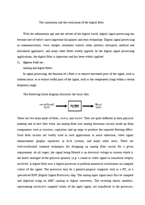
The simulation and the realization of the digital filterWith the information age and the advent of the digital world, digital signal processing has become one of today's most important disciplines and door technology. Digital signal processing in communications, voice, images, automatic control, radar, military, aerospace, medical and household appliances, and many other fields widely applied. In the digital signal processing applications, the digital filter is important and has been widely applied.1、figures Unit on :Analog and digital filtersIn signal processing, the function of a filter is to remove unwanted parts of the signal, such as random noise, or to extract useful parts of the signal, such as the components lying within a certain frequency range.The following block diagram illustrates the basic idea.There are two main kinds of filter, analog and digital. They are quite different in their physical makeup and in how they work. An analog filter uses analog electronic circuits made up from components such as resistors, capacitors and op amps to produce the required filtering effect. Such filter circuits are widely used in such applications as noise reduction, video signal enhancement, graphic equalisers in hi-fi systems, and many other areas. There are well-established standard techniques for designing an analog filter circuit for a given requirement. At all stages, the signal being filtered is an electrical voltage or current which is the direct analogue of the physical quantity (e.g. a sound or video signal or transducer output) involved. A digital filter uses a digital processor to perform numerical calculations on sampled values of the signal. The processor may be a general-purpose computer such as a PC, or a specialised DSP (Digital Signal Processor) chip. The analog input signal must first be sampled and digitised using an ADC (analog to digital converter). The resulting binary numbers, representing successive sampled values of the input signal, are transferred to the processor,which carries out numerical calculations on them. These calculations typically involve multiplying the input values by constants and adding the products together. If necessary, the results of these calculations, which now represent sampled values of the filtered signal, are output through a DAC (digital to analog converter) to convert the signal back to analog form.Note that in a digital filter, the signal is represented by a sequence of numbers, rather than a voltage or current.The following diagram shows the basic setup of such a system.Unit refers to the input signals used to filter hardware or software. If the filter input, output signals are separated, they are bound to respond to the impact of the Unit is separated, such as digital filters filter definition. Digital filter function, which was to import sequences X transformation into export operations through a series Y.According to figures filter function 24-hour live response characteristics, digital filters can be divided into two, namely, unlimited long live long live the corresponding IIR filter and the limited response to FIR filters. IIR filters have the advantage of the digital filter design can use simulation results, and simulation filter design of a large number of tables may facilitate simple. It is the shortcomings of the nonlinear phase; Linear phase if required, will use the entire network phase-correction. Image processing and transmission of data collection is required with linear phase filters identity. And FIR linear phase digital filter to achieve, but an arbitrary margin characteristics. Impact from the digital filter response of the units can be divided into two broad categories : the impact of the limited response (FIR) filters, and unlimited number of shocks to (IIR) digital filters.FIR filters can be strictly linear phase, but because the system FIR filter function extremity fixed at the original point, it can only use the higher number of bands to achieve their high selectivity for the same filter design indicators FIR filter called band than a few high-IIR 5-10 times, the cost is higher, Signal delay is also larger. But if the same linear phase, IIR filters must be network-wide calibration phase, the same section also increase the number of filters and network complexity. FIR filters can be used to achieve non-Digui way, not in a limited precision of a shock, and into the homes and quantitative factors of uncertainty arising from the impact of errors than IIR filter small number, and FIR filter can be used FFT algorithms, the computational speed. But unlike IIR filter can filter through the simulation results, there is no ready-made formula FIR filter must use computer-aided design software (such as MATLAB) to calculate. So, a broader application of FIR filters, and IIR filters are not very strict requirements on occasions.Unit from sub-functions can be divided into the following four categories :(1) Low-filter (LPF);(2) high-filter (HPF);(3) belt-filter (BPF);(4) to prevent filter (BSF).The following chart dotted line for the ideals of the filter frequency characteristics :A1(f) A2(f)10 f2cf 0 f2cf(a) (b)A3(f) A4(f)0 f1c f2cf 0 f1cf2cf(c) (d)(a)LPF (b)HPF (c)BPF (d)BSF2、MATLAB introducedMATLAB is a matrix laboratory (Matrix Laboratory) is intended. In addition to an excellent value calculation capability, it also provides professional symbols terms, word processing, visualization modeling, simulation and real-time control functions. MATLAB as the world's top mathematical software applications, with a strong engineering computing, algorithms research, engineering drawings, applications development, data analysis and dynamic simulation, and other functions, in aerospace, mechanical manufacturing and construction fields playing an increasingly important role. And the C language function rich, the use of flexibility, high-efficiency goals procedures. High language both advantages as well as low level language features. Therefore, C language is the most widely used programming language. Although MATLAB is a complete, fully functional programming environment, but in some cases, data and procedures with the external environment of the world is very necessary and useful. Filter design using Matlab, could be adjusted with the design requirements and filter characteristics of the parameters, visual simple, greatly reducing the workload for the filter design optimization.In the electricity system protection and secondary computer control, many signal processing and analysis are based on are certain types Yeroskipou and the second harmonics of the system voltage and current signals (especially at D process), are mixed with a variety of complex components, the filter has been installed power system during the critical components. Current computer protection and the introduction of two digital signal processing software main filter. Digital filter design using traditional cumbersome formula, the need to change the parameters after recalculation, especially in high filters, filter design workload. Uses MATLAB signal processing boxes can achieve rapid and effective digital filter design and simulation.MATLAB is the basic unit of data matrix, with its directives Biaodashi mathematics, engineering, commonly used form is very similar, it is used to solve a problem than in MATLAB C, Fortran and other languages End precision much the same thing. The popular MATLAB 5.3/Simulink3.0 including hundreds of internal function with the main pack and 30 types of tool kits (Toolbox). kits can be divided into functional tool kits and disciplines toolkit. MATLAB tool kit used to expand the functional symbols terms, visualization simulation modelling, word processing and real-time control functions. professional disciplines toolkit is a stronger tool kits, tool kits control, signal processing tool kit, tool kits, etc. belonging to such communicationsMATLAB users to open widely welcomed. In addition to the internal function, all the packages MATLAB tool kits are readable document and the document could be amended, modified or users through Yuanchengxu the construction of new procedures to prepare themselves for kits.3、Digital filter designDigital filter design of the basic requirementsDigital filter design must go through three steps :(1) Identification of indicators : In the design of a filter, there must be some indicators. These indicators should be determined on the basis of the application. In many practical applications, digital filters are often used to achieve the frequency operation. Therefore, indicators in the form of general jurisdiction given frequency range and phase response. Margins key indicators given in two ways. The first is absolute indicators. It provides a function to respond to the demands of the general application of FIR filter design. The second indicator is the relative indicators. Its value in the form of answers to decibels. In engineering practice, the most popular of such indicators. For phase response indicators forms, usually in the hope that the system with a linear phase frequency bands human. Using linear phase filter design with the following response to the indicators strengths:①it only contains a few algorithms, no plural operations;②there is delay distortion, only a fixed amount of delay; ③the filter length N (number of bands for N-1), the volume calculation for N/2 magnitude.(2) Model approach : Once identified indicators can use a previous study of the basic principles and relationships, a filter model to be closer to the target system.(3) Achieved : the results of the above two filters, usually by differential equations, systemfunction or pulse response to describe. According to this description of hardware or software used to achieve it.中文翻译数字滤波器的仿真与实现随着信息时代和数字世界的到来,数字信号处理已成为当今一门极其重要的学科和技术领域。
滤波器 外文翻译 外文文献 英文文献 用改进的窗函数设计FIR数字滤波器

Research on FIR Digital Filter Design Using an Improved Window FunctionTAN Jiajie , LUO Changyou, HUANG Sanwei ,DENG Xiaohui( Department of Physics and Electronic Information Science, Hengyang Normal University, Hengyang Hunan 421008, China)Abstract : Window function has been used to design a linear phase digital filer for long times, but the use o f optimization techniques for designing digital filter has become widespread in recent year A new met ho d has been proposed to improve FIR window function in this paper ,T he window function that combines with co sine sequences in linear is different from previous Hann ,Hamming and Blackman window function The paper also proposes linear programming to optimize characterization of FIR digital filter according to its magnitude condition, and gives out t he algorithm to design dig ital filter using the improved window function ,Finally , we have designed FIR filter using new window for simulation and compared w it h the filter designed by Hamming window, Blackman window function T he simulation results show that filters designed using this method to meet t he design specificationsKey words: improved window function; FIR digital filter ; window function; linear programming0 lead speechThe design method of FIR digital filters are mainly: window function method, frequency sampling method and the chebyshev etc corrugated approximation method [1-4]. Window function method is the most commonly used designing FIR digital filters, the simplest method of [4-5]. The essence of window function method is the truncated ideal impulse response to approximate the method petitions filter index. Frequency sampling method is a design optimization method for its shortcoming is when the design that use the variable is limited to a few samples values of transitional, cut-off frequency not easy control [3]. Chebyshev etc corrugated approximation method is a kind of optimization design, but existing computational complexity, big disadvantage computation [1-2].Window function method is simple in design, have closed form of formula, thus very practical. Defect is the stopband bandpass, cut-off frequency not easy control [2-3]. Digital filter, window function of auto-heating window function method of selecting, the key is: design to choose the appropriate window function, choose the right order number of digital filter, improve amplitude frequency characteristics, reduce Gibbs phenomenon, solve convergence problem [1-2]. [3] choose window function, through to Guass Guass window function improved, design a low-pass filter has better superiority; [4] the error information, using the known in the iteration process through the window function method continuously revised design result in filter order number, under the condition of invariable frequency response approximation, filter ideal frequency response. [5] use integer sequence, such as where Fibonacci sequence, Golomb sequence, ConwayHofstadter Recursive sequence, Triangular series produce window function to design the filter, its effect is better than that of classical design method. [6] choose dual window window function sequence of structure was system characteristics approximation error is the minimum; [7] will be well Saramaki Dolph - and Chebysheve window with the well designed, its effect FIR digital filters than Kaiser well; [8] put good effect in Hamming ReImann well well well and Kaiser window. [9] put forward a kind of exponential window function, this window function has the width can be adjusted with the window design characteristics, the digital filters have more centralized, Lord disc energy side-lobe less features. [10] using linear programming design linear phase fir filter ascending cosine to 100 % super bandwidth. [11] linear programming method is adopted to design digital filter. This paper USES the existing window function, and carry on the weighted combination, reference [10 or 11], and linear programming with long Hamming, Blackman window are compared. The advantages of this method is strong logicality, goal clear, easy to achieve, and to explore the best solutions.1 common window functionWindow function select principle: window function as focus on energy, Lord disc transitional steep; Reduce the window function spectrum side-lobe level, increase stopband attenuation, and reduce the stopband bandpass and ripple effect. Common window function have [1-4] : Rectangle window, Hanning window, Hamming window, Blackman window, Kaiser window. Window function method design idea of FIR filters is [1-2] : make sure the frequency response of ideal filter )(ωj d e H .The frequency response of practical design filter ∑-=-=10)()(N n j j e n h e H ωωTo approximate )(ωj d e H .For again ∑-=-=10)()(N n j j e n h e H ωωReverse transform get Finally use window function )(n w To truncate )(n h d ,mean h( n) =)(n h d )(n w .To truncate )(n h d ,Will produce gibbs phenomenon, all the window function choices to reduce this phenomenon for the purpose. Judge ideal window function mainly according to the following three criteria! The Lord is high double amplitude and its width should try to narrowThe amplitude side-lobe fast speed, the biggest drop side-lobe relative to the main valve should be as low as possible. #transitional requirements will try to narrow. Facts prove the two standard cannot simultaneously satisfy window function should be, so the twocompromise [1-3]. In order to reduce caused due to add window truncation ripple and transitional grows wider impact in engineering design common Hamming window and Kaiser window.2 improved window function [1-2] enumerated window function, Hanning window, Hamming window, Blackman window is cosine sequence andrectangular sequence of linear combination. In order to restrain the amplitude,side-lobe Hanning window, Hamming window on the basis of the second, add cosine, when the harmonic component design and ideal window function and related to the frequency response of different from Blackman window, window function improved form below )(14cos 12cos )(n N R N n c N n b a n ⎥⎦⎤⎢⎣⎡-+-+=ππω (1)Formula (1) of a, b, c undetermined, their size and given filter technology indexes related. For convenience, this window function length choice for odd. The next several special case discussion this type. Case 1, take a = 1, b = c = 0, for rectangular window. Condition 2, take a = 0.5, b = - 0.5, c = 0, for Hann window. Case 3, take a = 0.53, b = - 0.46, c = 0, for Hamming window.Situation, a = 4, b = 0 0.42 j c = 0.08, 5, Blackman window for. By aboveknowable, the improved window function with these four window function the nature, belong to the general form of the window function.3 improved window function algorithmAccording to the given filter technology index )(ωj d e H ,Determine the backlog filter unit, but by sampling response formula below ask out:ωπωππωd e e H n h j j d d ⎰-=)(21)( (2)Calculating the actual filter unit sampling response:h( n) = )(n h d )(n w (3)Filter the frequency response is:∑-=-=10)()(N n j j e n h e H ωω(4) Will formula (1) generation into the formula (4) :ξωππjn N n n d j e N n c N n b a h e H --=⎥⎦⎤⎢⎣⎡-+-+=∑14cos 12cos )(10)( (5) Reference [1-2] [10 or 11], consider FIR filters satisfy the first kind of linearphase conditions, For 21-N Accidentally symmetry, And N an odd number,ordering h ( n) = )(n h d ⨯⎥⎦⎤⎢⎣⎡-+-+14cos 12cos N n c N n b a ππ。
数字滤波器外文翻译

中文5590字毕业设计(外文翻译材料)2009年6月学 院: 专 业: 学生姓名: 指导教师: 电气与电子工程学院 电子信息工程0503DIGITAL FILTERSDigital filtering is one of the most powerful tools of DSP. Apart from the obvious advantages of virtually eliminating errors in the filter associated with passive component fluctuations over time and temperature, op amp drift (active filters), etc., digital filters are capable of performance specifications that would, at best, be extremely difficult, if not impossible, to achieve with an analog implementation. In addition, the characteristics of a digital filter can be easily changed under software control. Therefore, they are widely used in adaptive filtering applications in communications such as echo cancellation in modems, noise cancellation, and speech recognition.The actual procedure for designing digital filters has the same fundamental elements as that for analog filters. First, the desired filter responses are characterized, and the filter parameters are then calculated. Characteristics such as amplitude and phase response are derived in the same way. The key difference between analog and digital filters is that instead of calculating resistor, capacitor, and inductor values for an analog filter, coefficient values are calculated for a digital filter. So for the digital filter, numbers replace the physical resistor and capacitor components of the analog filter. These numbers reside in a memory as filter coefficients and are used with the sampled data values from the ADC to perform the filter calculations.The real-time digital filter, because it is a discrete time function, works with digitized data as opposed to a continuous waveform, and a new data point is acquired each sampling period. Because of this discrete nature, data samples are referenced as numbers such as sample 1, sample 2, sample 3, etc. Figure 1 shows a low frequency signal containing higher frequency noise which must be filtered out. This waveform must be digitized with an ADC to produce samples x(n). These data values are fed to the digital filter, which in this case is a lowpass filter. The output data samples, y(n), are used to reconstruct an analog waveform using a low glitch DAC.Digital filters, however, are not the answer to all signal processing filtering requirements. In order to maintain real-time operation, the DSP processor must be able to execute all the steps in the filter routine within one sampling clock period1/f s.A fast general purpose fixed-point DSP such as the ADSP-2189M at 75MIPS can 。
数字滤波器设计英文文献
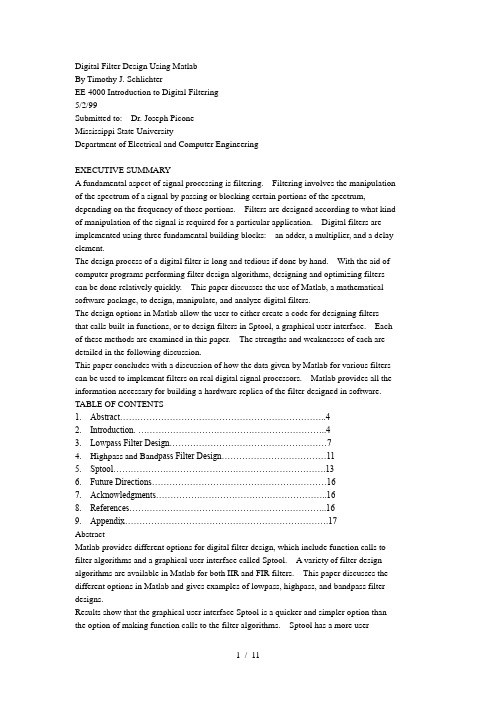
Digital Filter Design Using MatlabBy Timothy J. SchlichterEE 4000 Introduction to Digital Filtering5/2/99Submitted to: Dr. Joseph PiconeMississippi State UniversityDepartment of Electrical and Computer EngineeringEXECUTIVE SUMMARYA fundamental aspect of signal processing is filtering. Filtering involves the manipulation of the spectrum of a signal by passing or blocking certain portions of the spectrum, depending on the frequency of those portions. Filters are designed according to what kind of manipulation of the signal is required for a particular application. Digital filters are implemented using three fundamental building blocks: an adder, a multiplier, and a delay element.The design process of a digital filter is long and tedious if done by hand. With the aid of computer programs performing filter design algorithms, designing and optimizing filters can be done relatively quickly. This paper discusses the use of Matlab, a mathematical software package, to design, manipulate, and analyze digital filters.The design options in Matlab allow the user to either create a code for designing filters that calls built-in functions, or to design filters in Sptool, a graphical user interface. Each of these methods are examined in this paper. The strengths and weaknesses of each are detailed in the following discussion.This paper concludes with a discussion of how the data given by Matlab for various filters can be used to implement filters on real digital signal processors. Matlab provides all the information necessary for building a hardware replica of the filter designed in software. TABLE OF CONTENTS1. Abstract (4)2. Introduction. (4)3. Lowpass Filter Design (7)4. Highpass and Band pass Filter Design (11)5. Sptool (13)6. Future Directions (16)7. Acknowledgments (16)8. References (16)9. Appendix (17)AbstractMatlab provides different options for digital filter design, which include function calls to filter algorithms and a graphical user interface called Sptool. A variety of filter design algorithms are available in Matlab for both IIR and FIR filters. This paper discusses the different options in Matlab and gives examples of lowpass, highpass, and bandpass filter designs.Results show that the graphical user interface Sptool is a quicker and simpler option than the option of making function calls to the filter algorithms. Sptool has a more user-friendly environment since the spectrum of the filter is immediately displayed to the user, and the user can quickly zoom in and examine particular areas of interest in the spectrum (i.e. the passband). However, the shortcoming of Sptool is that it only displays the magnitude response of the filter, not the phase response.IntroductionA key element in processing digital signals is the filter. Filters perform direct manipulations on the spectra of signals. To completely describe digital filters, three basic elements (or building blocks) are needed: an adder, a multiplier, and a delay element. The adder has two inputs and one output, and it simply adds the two inputs together. The multiplier is a gain element, and it multiplies the input signal by a constant. The delay element delays the incoming signal by one sample. Digital filters can be implemented using either a block diagram or a signal flow graph. Figure 1 shows the three basic elements in block diagram form, and Figure 2 shows them in signal flow graph form.With the basic building blocks at hand, the two different filter structures can easily beimplemented. These two structures are Infinite Impulse Response (IIR) and FiniteImpulse Response (FIR), depending o n the form of the system’s response to a unit pulseinput. IIR filters are commonly implemented using a feedback (recursive) structure, whileFIR filters usually require no feedback (non-recursive).In the design of IIR filters, a commonly used approach is called the bilineartransformation. This design begins with the transfer function of an analog filter, thenperforms a mapping from the s-domain to the z-domain. Using differential equations, itcan be shown (Proakis 677) that the mapping from the s-plane to the z-plane isThis mapping results in a general form for an IIR filter with an arbitrary number of polesand zeros. The system response and the difference equation for this filter is as follows:This system response can be easily realized using a signal flow graphAn FIR filter has a difference equation ofBy taking the z-transform, the system response isThe realization of an FIR filter using a signal flow graph is straightforward.Matlab has several design algorithms that can be used to create and analyze both IIR and FIR digital filters. The IIR filters that can be created in Matlab are Butterworth, Chebyshev type 1 and 2, and elliptic. The FIR filter algorithms in Matlab are equiripple, least squares, and Kaiser window. The Matlab code required to implement these filters involves bilinear transformations and function calls to analog prototype filters. The following sections give examples of Matlab implementation of the IIR filters listed above. Lowpass Filter DesignUsing Matlab, a lowpass digital filter is designed using various analog prototypes: Chebyshev, Butterworth, and Elliptic. The optimum filter type is chosen on the basis of implementation complexity, magnitude response, and phase response. The design specifications for the filter are as follows:•Cutoff frequency = 1000Hz•Sample frequency = 8000Hz•Passband ripple = 0.5dB•Stopband attn. = 60dB•Transition band = 100HzMatlab Code (Chebyshev):% Lowpass digital filter with Chebyshev-I analog prototype%% Digital Filter Specifications:wp = 0.125*2*pi; % digital passband frequency in Hz (normalized)ws = 0.1375*2*pi; % digital stopband frequency in Hz (normalized)Rp = 0.5; % passband ripple in dBAs = 20; % stopband attenuation in dB% Analog Prototype Specifications:Fs = 1; T = 1/Fs;OmegaP = (2/T)*tan(wp/2); % prewarp prototype passband frequencyOmegaS = (2/T)*tan(ws/2); % prewarp prototype stopband frequency% Analog Chebyshev-1 Prototype Filter Calculation:[c, d] = chb1(OmegaP, OmegaS, Rp, As);% Bilinear Transformation:[b, a] = bilinear(cs, ds, Fs);%[db,mag,pha,grd,w] = freqz(b,a);plot(w*8000/2/pi,db);xlabel('frequency (Hz)'); ylabel('decibels'); title('Magnitude indB');This exact code is also used for the elliptic and Butterworth designs. The only change is in the filter calculations of each type. Instead of calling chb1(), the elliptic filter design calls a function “elliptic()” and the Butterworth design calls a function“butterworth()”. See the appendix for the Matlab code of the function chb1().The following figures show the magnitude and phase responses of each type of filter. Magnitude Response of Chebyshev FilterPhase of Chebyshev FilterMagnitude Response of Elliptic FilterPhase of Elliptic FilterMagnitude Response of Butterworth FilterPhase of Butterworth FilterThe Matlab code outputs the filter order and the filter coefficients. For this example, the Chebyshev filter order was nine. The elliptic filter had an order of five, and the Butterworth filter order was thirty-two.Several conclusions can be drawn about these low-pass filter designs from this simple example. First, in general, for a given set of design constraints, the elliptic filter design algorithm will result in the simplest filter (in terms of complexity). The most complex filter is the Butterworth filter with an order of thirty-two. In terms of passband ripple, the Butterworth filter gives the optimum response. In the passband, there is almost no ripple (monotonic). The elliptic and Chebyshev filters both have much more ripple in the passband. So, there is a tradeoff between these three different types of filters. In terms of magnitude response and complexity, the elliptic ripple is most likely the optimum choice. However, the elliptic ripple has a phase response that is more nonlinear than the Chebyshev and Butterworth filters. Therefore, if a sharp cutoff and relatively lowcomplexity is required, the choice would be the elliptic filter. If the phase response would need to be more linear, a Chebyshev or Butterworth filter should be chosen over the elliptic filter.Highpass andBandpass Filter DesignMatlab provides functions for implementing lowpass-to-highpass and lowpass-to-bandpass conversions. By providing a filter order, the passband ripple, and the 3dB cutoff frequency to the function cheby1(), a highpass filter can be designed. The filter order is found using the function chebord(). For a Butterworth prototype, the functions are butter() and buttord(). For the elliptic prototype, the functions are ellip() andellipord().The following Matlab code is used to design a Chebyshev highpass digital filter with a passband at 1100Hz and a 100Hz transition band.% Highpass Chebyshev Digital Filterws = 0.125*2*pi; % digital stopband frequency in rad/swp = 0.1375*2*pi; % digital passband frequency in rad/sRp = 0.5; % passband ripple in dBAs = 20;[N,wn] = cheb1ord(wp/pi,ws/pi,Rp,As);[b,a] = cheby1(N, Rp, wn, 'high');[db,mag,pha,grd,w] = freqz_m(b,a);plot(w*8000/2/pi,db);axis([800 1200 -22 1]);The following figure shows the magnitude response of the highpass filter.Magnitude Response of Chebyshev FilterBandpass filters are found using these same two functions. However, with bandpass filters, the passband and stopband frequencies (wp and ws) are two-element vectors since there are two passband frequencies and two stopband frequencies. The Matlab code below shows the design of an elliptic digital bandpass filter.% Bandpass Elliptic Digital Filterws = [0.3*pi 0.75*pi] %Stopband edge frequencywp = [0.4*pi 0.6*pi] %Passband edge frequencyRp = 0.5; %Passband ripple in dBAs = 20; %Stopband attenuation in dB[N,wn] = ellipord(wp/pi,ws/pi,Rp,As);[b,a] = ellip(N,Rp,As,wn);[db,mag,pha,grd,w] = freqz_m(b,a);plot(w*8000/2/pi,db);axis([500 3500 -22 1]);xlabel('frequency (Hz)'); ylabel('decibels'); title('MagnitudeResponse of Elliptic Filter');The following figure shows the magnitude response of the bandpass filter designed in the Matlab code above.Magnitude Response of Elliptic FilterSptoolMatlab has a very useful visualization tool for designing and analyzing digital filters called Signal Processing Tool, or Sptool. Sptool is a graphical user interface capable of analyzing and manipulating signals, filters, and spectra. For filter design, Sptool allows the user to select the filter design algorithm to use when creating the filter. The design algorithms included in Sptool are FIR filters (equiripple, least squares, Kaiser window) and IIR filters (Butterworth, Chebyshev type 1 and 2, elliptic). The user is also allowed to specify the type of filter (lowpass, bandpass, highpass, or bandstop). Sptool designs the filter and displays the magnitude response and the filter order.The figures below show actual Sptool screenshots for a lowpass filter design using the specifications given above. The Chebyshev Type 1 algorithm was used for thesescreenshots. By using the zoom options, different parts of the spectrum can be analyzed quickly and easily with Sptool. The second screenshot is a windowed view of the passband of the spectrum contained in the first screenshot.Future DirectionsDigital filters can be quickly and easily designed in Matlab using the methods described above. Sptool offers a much quicker way of designing and comparing different filters than using the function calls to the filter algorithms. However, Sptool allows the user to view the magnitude response of the filter, not the phase response. For some applications, the phase response may be more important than the magnitude response, so in these cases Sptool would not be as useful in determining the optimum filter design. Also, Sptool does not give a direct output of the filter coefficients. With the Matlab code given above, the filter coefficient are displayed to the user.The results from Matlab can be used directly to implement the digital filters on real DSPs. These results are all that is needed to draw a complete signal flow graph with adders, multipliers, and delay elements. The filter coefficients are used as the gain factors for the multipliers, and shift registers are used as the delay elements (for each z-nfactor).AcknowledgmentsMany thanks to Dr. Joseph Picone for his guidance, assistance, and time in the executionof this project.References•Hanselman, Duane, and Littlefield, Bruce. Mastering Matlab 5. Prentice Hall. Upper Saddle River, NJ, 1998.•Ingle, Vinay K. and Proakis, John G. Digital Signal Processing Using Matlab. PWS Publishing Company, 1997.•Proakis, John G. and Manolakis, Dimitris G. Digital Signal Processing: Principles, Algorithms, and Applications, 3rdEdition. Prentice Hall. Upper Saddle River, NJ,1996.•Ziemer, Rodger E., Tranter, William H., and Fannin, D. Ronald. Signals and Systems: Continuous and Discrete, 3rdEdition. Macmillan Publishing Company, 1993.Appendixfunction [b,a] = chb1(Wp, Ws, Rp, As);% Analog Lowpass Filter Design: Chebyshev-1%% [b,a] = chb1(Wp, Ws, Rp, As);% b = Numerator coefficients of Ha(s)% a = Denominator coefficients of Ha(s)% Wp = Passband edge frequency in rad/sec% Ws = Stopband edge frequency in rad/sec% Rp = Passband ripple in dB% As = Stopband attenuation in dB%if Wp <= 0error('Passband edge must be larger than 0')endif Ws <= Wperror('Stopband edge must be larger than Passband edge')endif (Rp <= 0) | (As < 0)error('PB ripple and/or SB attenuation must be larger than 0')endep = sqrt(10^(Rp/10)-1);A = 10^(As/20);OmegaC = Wp;OmegaR = Ws/ Wp;g = sqrt(A*A-1)/ep;N = ceil(log10(g+sqrt(g*g-1))/log10(OmegaR+sqrt(OmegaR*OmegaR-1))); fprintf('\n*** Chebyshev-1 Filter Order = %2.0f \n',N);[b,a] = ap_chb1(N, Rp, OmegaC);function [b,a] = ap_chb1(N, Rp, Omegac);% Chebyshev-1 Analog Lowpass Filter Prototype%% [b,a] = ap_chb1(N, Rp, Omegac);% b = nemerator polynomial coefficients% a = denominator polynomial coefficients% N = Order of the elliptical filter% Rp = Passband Ripple in dB% Omegac = cutoff frequency in rad/sec%[z,p,k] = cheb1ap(N,Rp);a = real(poly(p));aNn = a(N+1);p = p*Omegac;a = real(poly(p));aNu = a(N+1);k = k*aNu/aNn;b0 = k;B = real(poly(z));b = k*B;11 / 11。
IIR数字滤波器英文文献以及翻译

2013 届毕业设计(论文)英文文献及其翻译资料院、部:电气与信息工程学院学生姓名:指导教师:职称专业:电子信息工程班级:完成时间:2013年6月7日Signal processingSignal processing is an area of electrical engineering and applied mathematics that deals with operations on or analysis of signals, in either discrete or continuous time, to perform useful operations on those signals. Signals of interest can include sound, images, time-varying measurement values and sensor data, for example biological data such as electrocardiograms, control system signals, telecommunication transmission signals such as radio signals, and many others. Signals are analog or digital electrical representations of time-varying or spatial-varying physical quantities. In the context of signal processing, arbitrary binary data streams and on-off signalling are not considered as signals, but only analog and digital signals that are representations of analog physical quantities.HistoryAccording to Alan V. Oppenheim and Ronald W. Schafer, the principles of signal processing can be found in the classical numerical analysis techniques of the 17th century. They further state that the "digitalization" or digital refinement of these techniques can be found in the digital control systems of the 1940s and 1950s.Categories of signal processingAnalog signal processingAnalog signal processing is for signals that have not been digitized, as in classical radio, telephone, radar, and television systems. This involves linear electronic circuits such as passive filters, active filters, additive mixers, integrators and delay lines. It also involves non-linear circuits such as compandors, multiplicators (frequency mixers and voltage-controlled amplifiers), voltage-controlled filters, voltage-controlled oscillators and phase-locked loops.Discrete time signal processingDiscrete time signal processing is for sampled signals that are considered as defined only at discrete points in time, and as such are quantized in time, but not in magnitude.Analog discrete-time signal processing is a technology based on electronic devices such as sample and hold circuits, analog time-division multiplexers, analog delay lines and analog feedback shift registers. This technology was a predecessor of digital signal processing (see below), and is still used in advanced processing of gigahertz signals.The concept of discrete-time signal processing also refers to a theoretical discipline that establishes a mathematical basis for digital signal processing, without taking quantization error into consideration.Digital signal processingDigital signal processing is for signals that have been digitized. Processing is done by general-purpose computers or by digital circuits such as ASICs, field-programmable gate arrays or specialized digital signal processors (DSP chips). Typical arithmetical operations include fixed-point and floating-point, real-valued and complex-valued, multiplication and addition. Other typical operations supported by the hardware are circular buffers and look-up tables. Examples of algorithms are the Fast Fourier transform (FFT), finite impulse response (FIR) filter, Infinite impulse response (IIR) filter, and adaptive filters such as the Wiener and Kalman filters1.Digital signal processingDigital signal processing (DSP) is concerned with the representation of signals by a sequence of numbers or symbols and the processing of these signals. Digital signal processing and analog signal processing are subfields of signal processing. DSP includes subfields like: audio and speech signal processing, sonar and radar signal processing, sensor array processing, spectral estimation, statistical signal processing, digital image processing, signal processing for communications, control of systems, biomedical signal processing, seismic data processing, etc.The goal of DSP is usually to measure, filter and/or compress continuous real-world analog signals. The first step is usually to convert the signal from an analog to a digital form, by sampling it using an analog-to-digital converter (ADC), which turns the analog signal into a stream of numbers. However, often, the required output signal is another analog output signal, which requires a digital-to-analogconverter (DAC). Even if this process is more complex than analog processing and has a discrete value range, the application of computational power to digital signal processing allows for many advantages over analog processing in many applications, such as error detection and correction in transmission as well as data compression.[1]DSP algorithms have long been run on standard computers, on specialized processors called digital signal processors (DSPs), or on purpose-built hardware such as application-specific integrated circuit (ASICs). Today there are additional technologies used for digital signal processing including more powerful general purpose microprocessors, field-programmable gate arrays (FPGAs), digital signal controllers (mostly for industrial apps such as motor control), and stream processors, among others.[2]2. DSP domainsIn DSP, engineers usually study digital signals in one of the following domains: time domain (one-dimensional signals), spatial domain (multidimensional signals), frequency domain, autocorrelation domain, and wavelet domains. They choose the domain in which to process a signal by making an informed guess (or by trying different possibilities) as to which domain best represents the essential characteristics of the signal. A sequence of samples from a measuring device produces a time or spatial domain representation, whereas a discrete Fourier transform produces the frequency domain information, that is the frequency spectrum. Autocorrelation is defined as the cross-correlation of the signal with itself over varying intervals of time or space.3. Signal samplingMain article: Sampling (signal processing)With the increasing use of computers the usage of and need for digital signal processing has increased. In order to use an analog signal on a computer it must be digitized with an analog-to-digital converter. Sampling is usually carried out in two stages, discretization and quantization. In the discretization stage, the space of signals is partitioned into equivalence classes and quantization is carried out by replacing the signal with representative signal of the corresponding equivalence class. In thequantization stage the representative signal values are approximated by values from a finite set.The Nyquist–Shannon sampling theorem states that a signal can be exactly reconstructed from its samples if the sampling frequency is greater than twice the highest frequency of the signal; but requires an infinite number of samples . In practice, the sampling frequency is often significantly more than twice that required by the signal's limited bandwidth.A digital-to-analog converter is used to convert the digital signal back to analog. The use of a digital computer is a key ingredient in digital control systems.4. Time and space domainsMain article: Time domainThe most common processing approach in the time or space domain is enhancement of the input signal through a method called filtering. Digital filtering generally consists of some linear transformation of a number of surrounding samples around the current sample of the input or output signal. There are various ways to characterize filters; for example:∙ A "linear" filter is a linear transformation of input samples; other filters are "non-linear". Linear filters satisfy the superposition condition, i.e. if an input is a weighted linear combination of different signals, the output is an equally weighted linear combination of the corresponding output signals.∙ A "causal" filter uses only previous samples of the input or output signals; while a "non-causal" filter uses future input samples. A non-causal filter can usually be changed into a causal filter by adding a delay to it.∙ A "time-invariant" filter has constant properties over time; other filters such as adaptive filters change in time.∙Some filters are "stable", others are "unstable". A stable filter produces an output that converges to a constant value with time, or remains bounded within a finite interval. An unstable filter can produce an output that grows without bounds, with bounded or even zero input.A "finite impulse response" (FIR) filter uses only the input signals, while an "infinite impulse response" filter (IIR) uses both the input signal and previous samples of the output signal. FIR filters are always stable, while IIR filters may be unstable.Filters can be represented by block diagrams which can then be used to derive a sample processing algorithm to implement the filter using hardware instructions. A filter may also be described as a difference equation, a collection of zeroes and poles or, if it is an FIR filter, an impulse response or step response.The output of a digital filter to any given input may be calculated by convolving the input signal with the impulse response.5. Frequency domainMain article: Frequency domainSignals are converted from time or space domain to the frequency domain usually through the Fourier transform. The Fourier transform converts the signal information to a magnitude and phase component of each frequency. Often the Fourier transform is converted to the power spectrum, which is the magnitude of each frequency component squared.The most common purpose for analysis of signals in the frequency domain is analysis of signal properties. The engineer can study the spectrum to determine which frequencies are present in the input signal and which are missing.In addition to frequency information, phase information is often needed. This can be obtained from the Fourier transform. With some applications, how the phase varies with frequency can be a significant consideration.Filtering, particularly in non-realtime work can also be achieved by converting to the frequency domain, applying the filter and then converting back to the time domain. This is a fast, O(n log n) operation, and can give essentially any filter shape including excellent approximations to brickwall filters.There are some commonly used frequency domain transformations. For example, the cepstrum converts a signal to the frequency domain through Fourier transform, takes the logarithm, then applies another Fourier transform. This emphasizes thefrequency components with smaller magnitude while retaining the order of magnitudes of frequency components.6. Z-domain analysisWhereas analog filters are usually analysed on the s-plane; digital filters are analysed on the z-plane or z-domain in terms of z-transforms.Most filters can be described in Z-domain (a complex number superset of the frequency domain) by their transfer functions. A filter may be analysed in the z-domain by its characteristic collection of zeroes and poles.7. ApplicationsThe main applications of DSP are audio signal processing, audio compression, digital image processing, video compression, speech processing, speech recognition, digital communications, RADAR, SONAR, seismology, and biomedicine. Specific examples are speech compression and transmission in digital mobile phones, room matching equalization of sound in Hifi and sound reinforcement applications, weather forecasting, economic forecasting, seismic data processing, analysis and control of industrial processes, computer-generated animations in movies, medical imaging such as CAT scans and MRI, MP3 compression, image manipulation, high fidelity loudspeaker crossovers and equalization, and audio effects for use with electric guitar amplifiers8. ImplementationDigital signal processing is often implemented using specialised microprocessors such as the DSP56000, the TMS320, or the SHARC. These often process data using fixed-point arithmetic, although some versions are available which use floating point arithmetic and are more powerful. For faster applications FPGAs[3]might be used. Beginning in 2007, multicore implementations of DSPs have started to emerge from companies including Freescale and Stream Processors, Inc. For faster applications with vast usage, ASICs might be designed specifically. For slow applications, a traditional slower processor such as a microcontroller may be adequate. Also a growing number of DSP applications are now being implemented on Embedded Systems using powerful PCs with a Multi-core processor.信号处理信号处理是电气工程和应用数学领域,在离散的或连续的时间域处理和分析信号,以对这些信号进行所需的有用的操作。
数字滤波器设计译文

附件C :译文基于FPGA 的数字滤波器设计Chi-Jui Chou, Satish Mohanakrishnan, Joseph B. EvansTelecommunications& Information Sciences LaboratoryDepartment of Electrical & Computer EngineeringUniversity of KansasLawrence, KS 66045-2228摘要数字滤波算法被广泛应用在通用数字信号处理器中来实现音频应用,或者应用在专用的数字滤波芯片中以及利用在专用集成电路((ASICs )中实现高效率。
本文介绍了一种基于现场可编程门阵列(FPGA )来实现数字滤波器的方法。
基于FPGA 方法的优点在于数字滤波器的实现,与传统的DSP 芯片相比,拥有更高的采样率,与中等批量应用的ASIC 相比成本更低,与其他方法相比,更具有灵活性。
由于目前许多FPGA 架构在系统可编程,如果需求,器件的配置可以改变来实现不同的功能。
我们的例子说明FPGA 的方法是灵活多变的,提供性能媲美或优于传统方法。
1.介绍最常用的实现数字滤波算法是在通用的数字信号处理芯片中实现音频应用,或应用在专用的数字滤波芯片以及利用在专用集成电路(ASIC )实现高效率[9,14]。
本文介绍了一种基于实施现场可编程数字滤波算法门阵列(FPGA )的方法。
FPGA 技术的近来发展,已经使这些设备能实现传统保留在ASIC 中的各种应用 FPGA 非常适合于数据通路的设计,如所提及的数字滤波的应用。
新型可编程逻辑器件的密集型可以这样描述,一个不普通的算术运算比如所提及的数字滤波运算在一个很简单的单元中。
基于FPGA 方法的优点在于数字滤波器的实现,与传统的DSP 芯片相比,拥有更高的采样率,与中等批量应用的ASIC 相比成本更低,与其他替代方法相比,更具有灵活性。
数字滤波器文献翻译

文献翻译外文:Digital filterIn electronics, computer science and mathematics, a digital filter is a system that performs mathematical operations on a sampled, discrete-time signal to reduce or enhance certain aspects of that signal. This is in contrast to the other major type of electronic filter, the analog filter, which is an electronic circuit operating on continuous-time analog signals. An analog signal may be processed by a digital filter by first being digitized and represented as a sequence of numbers, then manipulated mathematically, and then reconstructed as a new analog signal (see digital signal processing). In an analog filter, the input signal is "directly" manipulated by the circuit.A digital filter system usually consists of an analog-to-digital converter to sample the input signal, followed by a microprocessor and some peripheral components such as memory to store data and filter coefficients etc. Finally a digital-to-analog converter to complete the output stage. Program Instructions (software) running on the microprocessor implement the digital filter by performing the necessary mathematical operations on the numbers received from the ADC. In some high performance applications, an FPGA or ASIC is used instead of a general purpose microprocessor, or a specialized DSP with specific paralleled architecture for expediting operations such as filtering.Digital filters may be more expensive than an equivalent analog filter due to their increased complexity, but they make practical many designs that are impractical or impossible as analog filters. Since digital filters use a sampling process and discrete-time processing, theyexperience latency (the difference in time between the input and the response), which is almost irrelevant in analog filters.Digital filters are commonplace and an essential element of everyday electronics such as radios, cellphones, and stereo receivers.Characterization of digital filtersA digital filter is characterized by its transfer function, or equivalently, its difference equation. Mathematical analysis of the transfer function can describe how it will respond to any input. As such, designing a filter consists of developing specifications appropriate to the problem (for example, a second-order low pass filter with a specific cut-off frequency), and then producing a transfer function which meets the specifications.The transfer function for a linear, time-invariant, digital filter can be expressed as a transfer function in the Z-domain; if it is causal, then it has the form:where the order of the filter is the greater of N or M. See Z-transform's LCCD equation for further discussion of this transfer function.This is the form for a recursive filter with both the inputs (Numerator) and outputs (Denominator), which typically leads to an IIR infinite impulse response behaviour, but if the denominator is made equal to unity i.e. no feedback, then this becomes an FIR or finite impulse response filter.Analysis techniquesA variety of mathematical techniques may be employed to analyze the behaviour of a given digital filter. Many of these analysis techniques may also be employed in designs, and often form the basis of a filter specification.Typically, one analyzes filters by calculating how the filter will respond to a simple input such as an impulse response. One can then extend this information to visualize the filter's response to more complex signals. Riemann spheres have been used, together with digital video, for this purpose.Impulse responseThe impulse response, often denoted h[k] or h k, is a measurement of how a filter will respond to the Kronecker delta function. For example, given a difference equation, one would set x0 = 1 and x k = 0 for and evaluate. The impulse response is a characterization of the filter's behaviour. Digital filters are typically considered in two categories: infinite impulse response (IIR) and finite impulse response (FIR). In the case of linear time-invariant FIR filters, the impulse response is exactly equal to the sequence of filter coefficients:IIR filters on the other hand are recursive, with the output depending on both current and previous inputs as well as previous outputs. The general form of the an IIR filter is thus:Plotting the impulse response will reveal how a filter will respond to a sudden, momentary disturbance.Difference equationIn discrete-time systems, the digital filter is often implemented by converting the transfer function to a linear constant-coefficient difference equation (LCCD) via the Z-transform. The discrete frequency-domain transfer function is written as the ratio of two polynomials. For example:This is expanded:and divided by the highest order of z:The coefficients of the denominator, a k, are the 'feed-backward' coefficients and the coefficients of the numerator are the 'feed-forward' coefficients, b k. The resultant linear difference equation is:or, for the example above:rearranging terms:then by taking the inverse z-transform:and finally, by solving for y[n]:This equation shows how to compute the next output sample, y[n], in terms of the past outputs, y[n−p], the present input, x[n], and the past inputs, x[n−p]. Applying the filter to an input in this form is equivalent to a Direct Form I or II realization, depending on the exact order of evaluation.Filter designMain article: Filter designThe design of digital filters is a deceptively complex topic.[1] Although filters are easily understood and calculated, the practical challenges of their design and implementation are significant and are the subject of much advanced research.There are two categories of digital filter: the recursive filter and the nonrecursive filter. These are often referred to as infinite impulseresponse (IIR) filters and finite impulse response (FIR) filters, respectively.[2]Filter realizationAfter a filter is designed, it must be realized by developing a signal flow diagram that describes the filter in terms of operations on sample sequences.A given transfer function may be realized in many ways. Consider how a simple expression such as ax+ bx+ c could be evaluated –one could also compute the equivalent x(a + b) + c. In the same way, all realizations may be seen as "factorizations" of the same transfer function, but different realizations will have different numerical properties. Specifically, some realizations are more efficient in terms of the number of operations or storage elements required for their implementation, and others provide advantages such as improved numerical stability and reduced round-off error. Some structures are better for fixed-point arithmetic and others may be better for floating-point arithmetic.Direct Form IA straightforward approach for IIR filter realization is Direct Form I, where the difference equation is evaluated directly. This form is practical for small filters, but may be inefficient and impractical (numerically unstable) for complex designs.[3] In general, this form requires 2N delay elements (for both input and output signals) for a filter of order N.Direct Form IIThe alternate Direct Form II only needs N delay units, where N is the order of the filter –potentially half as much as Direct Form I. This structure is obtained by reversing the order of the numerator and denominator sections of Direct Form I, since they are in fact two linear systems, and the commutativity property applies. Then, one will notice that there are two columns of delays (z− 1) that tap off the center net, and these can be combined since they are redundant, yielding the implementation as shown below.The disadvantage is that Direct Form II increases the possibility of arithmetic overflow for filters of high Q or resonance.[4]It has been shown that as Q increases, the round-off noise of both direct form topologies increases without bounds.[5]This is because, conceptually, the signal is first passed through an all-pole filter (which normally boosts gain at the resonant frequencies) before the result of that is saturated, then passed through an all-zero filter (which often attenuates much of what the all-pole half amplifies).Cascaded second-order sectionsA common strategy is to realize a higher-order (greater than 2) digital filter as a cascaded series of second-order "biquadratric" (or "biquad") sections[6] (see digital biquad filter). Advantages of this strategy is that the coefficient range is limited. Cascading direct form II sections result in N delay elements for filter order of N. Cascading direct form I sections result in N+2 delay elements since the delay elements of the input of any section (except the first section) are a redundant with the delay elements of the output of the preceding section.文献翻译译文:数字滤波在电子学、计算机科学和数学中,数位滤波器是在一个系统上执行一个采样,在离散时间上对信号进行的数学运算,以减少或增加这种信号的某些方面。
- 1、下载文档前请自行甄别文档内容的完整性,平台不提供额外的编辑、内容补充、找答案等附加服务。
- 2、"仅部分预览"的文档,不可在线预览部分如存在完整性等问题,可反馈申请退款(可完整预览的文档不适用该条件!)。
- 3、如文档侵犯您的权益,请联系客服反馈,我们会尽快为您处理(人工客服工作时间:9:00-18:30)。
文献翻译外文:Digital filterIn electronics, computer science and mathematics, a digital filter is a system that performs mathematical operations on a sampled, discrete-time signal to reduce or enhance certain aspects of that signal. This is in contrast to the other major type of electronic filter, the analog filter, which is an electronic circuit operating on continuous-time analog signals. An analog signal may be processed by a digital filter by first being digitized and represented as a sequence of numbers, then manipulated mathematically, and then reconstructed as a new analog signal (see digital signal processing). In an analog filter, the input signal is "directly" manipulated by the circuit.A digital filter system usually consists of an analog-to-digital converter to sample the input signal, followed by a microprocessor and some peripheral components such as memory to store data and filter coefficients etc. Finally a digital-to-analog converter to complete the output stage. Program Instructions (software) running on the microprocessor implement the digital filter by performing the necessary mathematical operations on the numbers received from the ADC. In some high performance applications, an FPGA or ASIC is used instead of a general purpose microprocessor, or a specialized DSP with specific paralleled architecture for expediting operations such as filtering.Digital filters may be more expensive than an equivalent analog filter due to their increased complexity, but they make practical many designs that are impractical or impossible as analog filters. Since digital filters use a sampling process and discrete-time processing, theyexperience latency (the difference in time between the input and the response), which is almost irrelevant in analog filters.Digital filters are commonplace and an essential element of everyday electronics such as radios, cellphones, and stereo receivers.Characterization of digital filtersA digital filter is characterized by its transfer function, or equivalently, its difference equation. Mathematical analysis of the transfer function can describe how it will respond to any input. As such, designing a filter consists of developing specifications appropriate to the problem (for example, a second-order low pass filter with a specific cut-off frequency), and then producing a transfer function which meets the specifications.The transfer function for a linear, time-invariant, digital filter can be expressed as a transfer function in the Z-domain; if it is causal, then it has the form:where the order of the filter is the greater of N or M. See Z-transform's LCCD equation for further discussion of this transfer function.This is the form for a recursive filter with both the inputs (Numerator) and outputs (Denominator), which typically leads to an IIR infinite impulse response behaviour, but if the denominator is made equal to unity i.e. no feedback, then this becomes an FIR or finite impulse response filter.Analysis techniquesA variety of mathematical techniques may be employed to analyze the behaviour of a given digital filter. Many of these analysis techniques may also be employed in designs, and often form the basis of a filter specification.Typically, one analyzes filters by calculating how the filter will respond to a simple input such as an impulse response. One can then extend this information to visualize the filter's response to more complex signals. Riemann spheres have been used, together with digital video, for this purpose.Impulse responseThe impulse response, often denoted h[k] or h k, is a measurement of how a filter will respond to the Kronecker delta function. For example, given a difference equation, one would set x0 = 1 and x k = 0 for and evaluate. The impulse response is a characterization of the filter's behaviour. Digital filters are typically considered in two categories: infinite impulse response (IIR) and finite impulse response (FIR). In the case of linear time-invariant FIR filters, the impulse response is exactly equal to the sequence of filter coefficients:IIR filters on the other hand are recursive, with the output depending on both current and previous inputs as well as previous outputs. The general form of the an IIR filter is thus:Plotting the impulse response will reveal how a filter will respond to a sudden, momentary disturbance.Difference equationIn discrete-time systems, the digital filter is often implemented by converting the transfer function to a linear constant-coefficient difference equation (LCCD) via the Z-transform. The discrete frequency-domain transfer function is written as the ratio of two polynomials. For example:This is expanded:and divided by the highest order of z:The coefficients of the denominator, a k, are the 'feed-backward' coefficients and the coefficients of the numerator are the 'feed-forward' coefficients, b k. The resultant linear difference equation is:or, for the example above:rearranging terms:then by taking the inverse z-transform:and finally, by solving for y[n]:This equation shows how to compute the next output sample, y[n], in terms of the past outputs, y[n−p], the present input, x[n], and the past inputs, x[n−p]. Applying the filter to an input in this form is equivalent to a Direct Form I or II realization, depending on the exact order of evaluation.Filter designMain article: Filter designThe design of digital filters is a deceptively complex topic.[1] Although filters are easily understood and calculated, the practical challenges of their design and implementation are significant and are the subject of much advanced research.There are two categories of digital filter: the recursive filter and the nonrecursive filter. These are often referred to as infinite impulseresponse (IIR) filters and finite impulse response (FIR) filters, respectively.[2]Filter realizationAfter a filter is designed, it must be realized by developing a signal flow diagram that describes the filter in terms of operations on sample sequences.A given transfer function may be realized in many ways. Consider how a simple expression such as ax+ bx+ c could be evaluated –one could also compute the equivalent x(a + b) + c. In the same way, all realizations may be seen as "factorizations" of the same transfer function, but different realizations will have different numerical properties. Specifically, some realizations are more efficient in terms of the number of operations or storage elements required for their implementation, and others provide advantages such as improved numerical stability and reduced round-off error. Some structures are better for fixed-point arithmetic and others may be better for floating-point arithmetic.Direct Form IA straightforward approach for IIR filter realization is Direct Form I, where the difference equation is evaluated directly. This form is practical for small filters, but may be inefficient and impractical (numerically unstable) for complex designs.[3] In general, this form requires 2N delay elements (for both input and output signals) for a filter of order N.Direct Form IIThe alternate Direct Form II only needs N delay units, where N is the order of the filter –potentially half as much as Direct Form I. This structure is obtained by reversing the order of the numerator and denominator sections of Direct Form I, since they are in fact two linear systems, and the commutativity property applies. Then, one will notice that there are two columns of delays (z− 1) that tap off the center net, and these can be combined since they are redundant, yielding the implementation as shown below.The disadvantage is that Direct Form II increases the possibility of arithmetic overflow for filters of high Q or resonance.[4]It has been shown that as Q increases, the round-off noise of both direct form topologies increases without bounds.[5]This is because, conceptually, the signal is first passed through an all-pole filter (which normally boosts gain at the resonant frequencies) before the result of that is saturated, then passed through an all-zero filter (which often attenuates much of what the all-pole half amplifies).Cascaded second-order sectionsA common strategy is to realize a higher-order (greater than 2) digital filter as a cascaded series of second-order "biquadratric" (or "biquad") sections[6] (see digital biquad filter). Advantages of this strategy is that the coefficient range is limited. Cascading direct form II sections result in N delay elements for filter order of N. Cascading direct form I sections result in N+2 delay elements since the delay elements of the input of any section (except the first section) are a redundant with the delay elements of the output of the preceding section.文献翻译译文:数字滤波在电子学、计算机科学和数学中,数位滤波器是在一个系统上执行一个采样,在离散时间上对信号进行的数学运算,以减少或增加这种信号的某些方面。