图示均衡器
现代音响与调音技术-第5章1-图示均衡器、压扩器、电子分频器
输 出 信 号 电 平
所以,在信号超出阈值电平后压缩器降低增益 和在输入信号降至低于阈值电平之后压缩器恢复增 益的速度必须确定,也就是它们应按要求跟上信号 的变化,可见此速度分别取决于信号增加的时间和 恢复的时间。 虽然人耳对信号响度的感觉与其均方根值成比例, 短时间内的高峰值并不显著增加信号的响度。但
一般常用的专业多频段图示均衡器有单通道15 段和31段及双通道15段和31段四种。双通道均衡器 两个通道的频率特性独立调整,互不影响。一般15 段均衡器的中心频率按2/3倍频程选取, 31段频率 均衡器,以选择1/3倍频程为好,各频率点的最大提 升和最大衰减因均衡器不同而异,一般多为±15dB 和±12dB。
8k-12k
4k-8k
声音各个波段的作用:下表提供人听觉上下限内声音各 个波段对听觉感受的影响,按着频率由高到底排列。
这个频率的穿透力很强。人耳耳腔的谐振频率 是1-4KHz所以人耳对这个频率也是非常敏感 的。如果频率成分过少,听觉能力会变差,语 音显得模糊不清了。如果这个频率成分过强了, 则会产生咳声的感觉。2~4kHz对声音的亮度 影响很大,这段声音一般不宜衰减。有适当的 提升可以提高声音的明亮度和清晰度,但是在 4kHz时不能有过多的突出,否则女声的齿音会 部分女声、以及大部分 过重。 吹奏类乐器
第5章 音频信号处理设备
什么是音频信号处理设备?
它是一个总称。音频信号处理设备(Audio Signal Processor)是指在音响系统中对音频信 号进行修饰和加工处理的部件、装臵或设备。 在专业音响设备中,可以作为一个设备的部件 出现在调音台,扩音机内部,也可以做成一台 完整的独立设备,作为扩声等音响系统的组成 部分。 由于在专业音响系统中,音频信号处理设备 通常是围绕调音台连接的,因此也将独立的信 号处理设备称为调音台的周: 采用音频信号发生器等设备,对厅堂的频率响应曲 线进行测定。然后在均衡器上进行均衡处理,使厅堂的 实际频响曲线接近平直,从而改善厅堂的声场,提高声 音的传播质量。这种方法通常用在音乐厅、剧院等专业 演出场所,它需要有一定的设备条件。
3G-Sys 2231 双频道图示均衡器用户说明书
1.注意事项2.功能特点3.技术规格4.面板介绍目 录18342763.1 性能参数指标3.2 曲线图:5.背板介绍6.电源要求一、注意事项请勿擅自打开本体本体中使用了高压元件。
请勿打开外壳,试图检查或改装本体,以免遭受电击的危险。
由于用户的改装而引起机器性能下降或是误操作,将不属产品质量保证范围之内。
不要损坏电源线在插上或是拔下电源线时请握住电源线的插头部份。
不要用湿的手去拔取或触摸电源线,这会导致短路或是触电事故。
不要将电源线铺设在本体和家具之下,物体之间。
也不要将电源线和其他的电源线捆在一起,不要让电源线打结或是将其放置在人经常走动的地方。
严禁水滴和异物切勿从本体的通气孔或其他开口处插入或掉入如发夹、铁钉和硬币之类的金属物以及诸如纸张、火柴之类的易燃物,因为这会引起误操作或是火灾和电击。
万一水滴或异物进入了本体,请让维修中心或经销商做一次检查。
万一发现异常在使用时万一发现有异常的噪音或气味产生,请立即关闭电源,从插座上拔下电源线,并向经销商或维修中心咨询,要求做一次检查。
当长期不使用时当您长时间不使用时,请关掉电源并从电源插座上拔下电源线。
这将防止由于本体的意外情况而引起的火灾。
说 明:!在三角形内,用箭头表示的“闪电”标记表示警告用户此处机内为危险电压,使用时请必备接地并注意操作。
三角形内用惊叹号标注的是提醒用户为重要操作,请严格依照使用说明进行。
二、功能特点尊敬的用户:当您使用本公司的EQ2231产品时,请认真阅读本手册,严格按照本手册的使用方法进行操作.如有疑问,请向当地特约代理商咨询或登陆本公司网站查询.EQ2231是一台性能优良、功能完善的通用图示均衡,适用于各类系统音响工程的调音场合。
其性能特点如下:1.双通道,每通道有30个均衡频点,涵盖整个音频范围。
每个频点的可调范围达+/-15dB, 并且每个频点的Q值是恒定的。
2.中点的旁路(BAPASS)功能。
当调节某个均衡频点的推子到中点,即不使用均衡功 能时,该频点即被旁路,从而得到更高质保真的音效。
喇叭杀手培训班
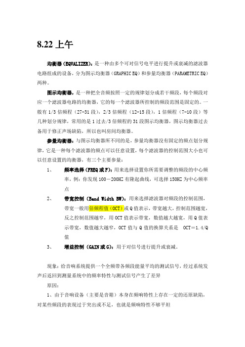
8.22上午均衡器(EQVALIZER):是一种由多个可对信号电平进行提升或衰减的滤波器电路组成的设备,分为图示均衡器(GRAPHIC EQ)和参量均衡器(PARAMETRIC EQ)两种。
图示均衡器,是一种把全音频按照一定的规律划分成若干频段,每个频段对应一个滤波器电路的均衡器,它的每一个滤波器所控制的频段范围是固定的。
一般有1/3倍频程(27-31段),2/3倍频程(12-15段),1倍频程(7-10段)等几种划分规律,常用的是1过去/3倍频程的31段图示均衡器,图示均衡器过去备用于修正声场缺陷,所以也叫房间均衡器。
参量均衡器:与图示均衡器所不同的是,参量均衡器没有固定的频点划分规律,它是一种每个滤波器的频点可以任意设置,每个滤波器的控制范围大小也可以任意设置的均衡器,有三个主要参量:1、频率选择(FREQ或F):用来选择设置你所需要调整的频段的中心频率,例:你发现100-200HZ有隆起曲线,可选择150HZ为中心频率点2、带宽控制(Band Width BW):用来选择滤波器对频段的控制范围,带宽一般用倍频程值(OCT)或Q值表示,带宽越大,控制范围越宽,反之控制范围越窄,用OCT值表示带宽,数值越大越宽,用Q值表示带宽,数值越大越窄,OCT值与Q值的换算关系是 OCT=1.4/Q值3、增益控制(GAIN或G):用于对信号进行提升或衰减。
现象:给音响系统提供一个全频带各频段能量平均的测试信号,经过系统发声后返回到测量系统中的频率特性与测试信号产生了差异原因:1、由于音响设备(主要是音箱)本身在频响特性上存在一定的还原缺陷,对某些频段的表现过于突出或不足,也就是频响特性不够平坦2、由于音响系统所处的环境引起的什么是扩声系统?扩声系统是指由音响系统以及音响系统所处的使用环境共同组成的声音还原扩大系统。
声场缺陷对扩声特性的影响(少图):由于任何使用环境都存在反射声面,有反射面就会有反射声,反射声由于和直达声路径不同,到达听音区的时间就不同,反射声与直达声就可能存在相位相同或相反,以及交替变化的情况,当反射声与直达声同相时,能量叠加产生“波峰”,而反射声与直达声反相时,能量抵消产生“波谷”,最后导致曲线不平坦。
均衡器——专业信号处理设备基础知识
专业信号处理设备专业音响系统与家用音响系统的明显区别是拥有较多的专业信号处理设备,因为主要与调音台连接,故称它们为周边设备。
专业信号处理设备的作用是配合调音台对音频信号进行各种处理和修饰,达到美化音色和保护后级设备的作用。
常用的专业信号处理设备有:均衡器、压限器、效果器、激励器和电子分频器等。
第一节均衡器均衡器是一种用来对频响曲线进行调节的音频设备,换名话说,均衡器能对不同频率的声音信号中过多的频率成分。
因此,它能补偿由于各种原因造成的信号欠缺的频率成分,也能抑制信号中过多的频率成分。
例如,均衡器可以抑制频率为60~250Hz的低频交流声,也可以抑制频率为6~12kHz的高频噪声;利用均衡器还可以进行音调调节和音色加工。
均衡器的原意是将传输系统中不平衡的频率特性用相反的特性曲线进行频率均衡,在此基础上增加了音色加工和美化的功能。
均衡器的作用主要如下。
①校正各种音频设备产生的频率失真,以获得平坦响应。
②改善室内声场,改善由于房间共振特性或吸声特性不均匀而造成的传输增益(频率)失真,确保其频率特性平直。
③抑制声反馈,提高系统传声增益,改善扩声音质。
④提高语言清晰度和自然度。
⑤在音响艺术创作中,用于刻画乐器和演员的音色个性,提高音响艺术的表现效果。
均衡器的种类很多,但基本上工作原理都是相同的。
它们都是将音频信号的全频带(20Hz~20kHz)或全频带的主要部分,按一定的规律分成几个甚至几十个频点(也称频段),再利用LC串联谐振的选频特性,分别进行提升或衰减,从而获得所希望的频率校正曲线。
根据均衡器所使用的电路不同,可分为有源均衡器和无源均衡器;根据中心频率不同,可分为低频均衡器、中频均衡器、高频均衡器和组合式均衡器;根据其他参数是否可调,可分为图示均衡器和参量均衡器。
本节主要介绍图示均衡器。
一、图示均衡器图示均衡器是组合均衡器中的一种,它是以中心频率为横坐标,控制电平为纵坐标,滑动电位器摆出的形状就形成了频响曲线,大致反映了所用均衡器的频响特性,操作起来既简单又直观,所以称它为图示均衡器(Graphic Equalizer)。
图示均衡器的使用技巧
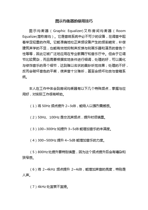
图示均衡器的使用技巧图示均衡器(Graphic Equalizer)又称房间均衡器(Room Equalizer,简称房均)。
它是音响系统中必不可少的设备,在调音中起着举足轻重的作用。
它能准确地校正声频设备产生的频率畸变,补偿建筑声学的不足,也能有效地抑制声反馈与刻画乐器和演员的音色个性等等,因此它被广泛地应用在专业歌舞厅和音乐厅中。
但由于它调节比较复杂,而且需要根据实地条件进行细调,处理的好,可以美化与修饰音乐的各个细节,达到难以名状的美妙听觉效果;处理的不好,反而会破坏音色的平衡,使声音十分难听,甚至会损坏功放与音箱系统。
本人在工作中体会到房间均衡器有以下几个特殊频点,掌握与应用好,对实际工作很有帮助。
(1)将50Hz频点提升2~3dB,能给人以强烈震撼感。
(2)50Hz、100Hz是交流声频点,提升时须慎重。
(3)100~300Hz如提升3~5dB能增加音乐的丰满度。
(4)300~500Hz提升4~5dB能增加音乐的力度。
(5)800Hz处提升要特别慎重,因为这个频点提升后会有嘈杂和狭窄感。
(6)将2~4kHz频点提升2~4dB,能增加声音的亮度,特别是人声。
(7)4kHz处宜衰不宜提。
(8)6800Hz提升过高会产生尖叫声,特别是接有话筒的扩音系统,会引起高频反馈啸叫。
(9)8kHz以上稍加提升,就能增加声音层次和色彩感。
(10)10kHz以上频段最好不要提升或不要提太高,要控制在3dB以内为宜。
如感到音频段量感不足,可在均衡器后加接音色激励器来补偿。
总之,任一频点的提升量和衰减量都不要过大,最忌的就是想邻几个频点增益相差太大,此时最易诱发音乐的频率失真。
Tweeq双31段图示均衡器

2SAFETY INSTRUCTIONS1. Read Instructions — All the safety and operation instructionsshould be read before this product is operated.2. Retain Instructions — The safety and operating instructionsshould be kept for future reference.3. Heed Warnings — All warnings on this product and in theseoperating instructions should be followed.4. Follow Instructions — All operating and other instructionsshould be followed.5. Water and Moisture — This product should not be used nearwater – for example, near a bathtub, washbowl, kitchen sink, laundry tub, in a wet basement, near a swimming pool, etc.6. Cleaning — Clean only with a dry cloth.7. V entilation — This product should be situated so that its locationor position does not interfere with its proper ventilation. For example, the Component should not be situated on a bed, sofa, rug, or similar surface that may block any ventilationopenings, or placed in a built-in installation such as a bookcase or cabinet that may impede the fl ow of air through ventilation openings.8. Heat — This product should be situated away from heatsources such as radiators, or other devices which produce heat.9. Power Sources — This product should be connected to apower supply only of the type described in these operation instructions or as marked on this product. 10. Power Cord Protection — Power supply cords should be routedso that they are not likely to be walked upon or pinched by items placed upon or against them, paying particular attention to cords at plugs, convenience receptacles, and the point where they exit this product. 11. Object and Liquid Entry — Care should be taken so thatobjects do not fall on, and liquids are not spilled into, this product.12. Damage Requiring Service — This product should be servicedonly by qualifi ed service personnel when: A. The power-supply cord or the plug has been damaged; or B. Objects have fallen, or liquid has spilled into this product; or C. This product has been exposed to rain; orD. This product does not appear to operate normally or exhibits a marked change in performance; orE. This product has been dropped, or its chassis damaged.13. Servicing — The user should not attempt to service thisproduct beyond those means described in this operating manual. All other servicing should be referred to the Tapco Service Department.14. To prevent electric shock, do not use this polarized plug withan extension cord, receptacle or other outlet unless the blades can be fully inserted to prevent blade exposure.Pour préevenir les chocs électriques ne pas utiliser cette fi che polariseé avec un prolongateur, un prise de courant ou une autre sortie de courant, sauf si les lames peuvent être insérées à fond sans laisser aucune pariie à découvert.15. Grounding or Polarization — Precautions should be taken sothat the grounding or polarization means of this product is not defeated.16. Power Precaution — Unplug this product during lightningstorms or when unused for long periods of time.17. This apparatus does not exceed the Class A/Class B(whichever is applicable) limits for radio noise emissions from digital apparatus as set out in the radio interferenceregulations of the Canadian Department of Communications.ATTENTION —Le présent appareil numérique n’émet pas de bruits radioélectriques dépassant las limites applicables aux appareils numériques de class A/de class B (selon le cas) prescrites dans le règlement sur le brouillage radioélectrique édicté par les ministere des communications du Canada.The lightning flash with arrowhead symbol within an equilateral triangle is intended to alert the user to the presence of uninsulated “dangerous voltage ” within the product ’s enclosure that may beof sufficient magnitude to constitute a risk of electric shock to persons. Le symbole éclair avec point de fl èche à l'int érieur d'un triangle équilat éral est utilis é pour alerter l'utilisateur de la pr ésence à l'int érieur du coffret de “voltage dangereux ” non isol é d'ampleur suffisante pour constituer un risque d'él éctrocution.The exclamation point within an equilateral triangle is intended to alert the user of the presence of important operating and maintenance (servicing) instructions in the literature accompanying the appliance. Le point d'exclamation à l'int érieur d'un triangle équilat éral est employ é pour alerter les utilisateurs de la pr ésence d'instructions importantes pour le fonctionnement et l'entretien (service) dans le livret d'instruction accompagnant l'appareil.Part No. 0009427 Rev. A 1/04©2004 LOUD Technologies Inc. All Rights Reserved.3What me, read a manual?Before you begin, please make sure you read the Safety Instructions on page 2 and Getting Started on page 4.Your new TAPCO ® T •231 is designed to set up quickly and operate easily. We know it ’s often seen as a sign of weakness to read a manual, along with asking for directions when lost, but maybe you can read the rest when nobody is looking.It is important to keep your receipt in a safe place, and not a bad idea to write your product information here for future reference (i.e., insurance claims, tech support, return authorization, etc.).Duration Per Day Sound Level dBA, TypicalIn Hours Slow ResponseExample8 90 Packed garage concert 6 924 95 VW Bus Peace Train 3 97 2 100 Cranked psychedelic tunes 1.5 102 1105 High speed chase on C.H.I.P .s 0.51100.25 or less115Loudest parts at a Heavy Metal concertProduct Serial #:Purchased at:Date of purchase:18. Exposure to extremely high noise levels may cause permanenthearing loss. Individuals vary considerably in susceptibility to noise-induced hearing loss, but nearly everyone will lose some hearing if exposed to suf fi ciently intense noise for a period of time. The U.S. Government ’s Occupational Safety and Health Administration (OSHA) has speci fi ed the permissible noise level exposures shown in the following chart.According to OSHA, any exposure in excess of these permissible limits could result in some hearing loss. To ensure against potentially dangerous exposure to high sound pressure levels, it is recommended that all persons exposed to equipment capable of producing high sound pressure levels use hearing protectors while the equipment is in operation. Ear plugs or protectors in the ear canals or over the ears must be worn when operating the equipment in order to prevent permanent hearing loss if exposure is in excess of the limits set forth here.Getting StartedThe following steps will help you set up your T•231, and get the levels just right.SETTINGS:1.Be sure the T•231’s POWER switch is off.2.Set all the sliders to their center positions and all theswitches out.CONNECTIONS:1. Using balanced or unbalanced cables, connectyour mixer’s main outputs to the T•231’s inputs,and the T•231’s outputs to your amplifer’s (orpowered speakers’) inputs.If you are using the T•231 in a channel’s insert,connect your mixer’s channel inserts to yourT•231’s INPUTs and OUTPUTs.Note: The T•231 31-Band GraphicEqualizer is designed to be inserted“in-line” with the signal as aserial device. This means that theentire signal is routed through theprocessor, in contrast to a parallel device where the processed signal is mixed back with the unprocessed signal, like a reverb or echo.2. Connect the cables using either XLR or 1/4”TRS connectors (balanced), or 1/4” TS or RCAconnectors (unbalanced).• The XLR, TRS, and RCA inputs for each channelare wired in parallel. Use only one input per channel.• The XLR, TRS, and RCA outputs for each channel are wired in parallel.• The balanced XLR connectors are wired asfollows:Pin 1 = shield (ground)Pin 2 = hot (+)Pin 3 = cold (–)• The 1/4” TRS connectors are wired as follows:Tip = hot (+)Ring = cold (–)Sleeve = shield (ground)3. Plug all the sound system components into suitableAC outlets, properly grounded and capable ofdelivering adequate current.4. Turn all the equipment on. If you are monitoring thesignal through speakers, turn the power amplifi eron last to avoid getting any pops or thumpsthrough your speakers. SET THE CONTROLS:1.Make sure your signal source is turned up anddelivering signal to the T•231. The signal shouldpass through the T•231 unaffected because theCHAN 1 and 2 BYPASS buttons are out and thesignal processing circuitry is bypassed.2.Push in the CHAN 1 and 2 BYPASS buttons toenable the graphic equalizer circuits.3.You can turn up and down each individual sliderand hear how it affects the sound.4.You can turn up and down the input LEVEL controlsto make it louder or softer. When the LEVEL control is at the center detent, it is at unity gain (it doesn’t boost or cut the signal).Things To Remember:• When you shut down yourequipment, turn off the amplifi ersfi rst. When powering up, turn on theamplifi ers last.• Save the shipping box andpacking material! You may need itsomeday.CLOSER4ContentsSafety Instructions (2)Getting Started (4)Introduction (6)Hookup Diagrams (8)Typical Hookup: In-line with Main Outputs (8)Alternate Hookup: Individual Channel or Main Inserts ..8T•231 Features (9)FRONT PANEL FEATURES (9)1. EQ Sliders (9)2. Input LEVEL (9)3. HI-PASS (9)4. LOW-PASS (9)5. BYPASS (9)6. CLIP (9)7. RANGE (9)8. POWER (9)REAR PANEL FEATURES (10)9. Line Cord Socket and Fuse (10)10. AC Select Switch (10)11. GND LIFT Switch (10)12. OUTPUTS (10)13. INPUTS (10)GENERAL PRECAUTIONS AND CONSIDERATIONS (11)Rack Mounting (11)Thermal Considerations (11)AC Power Considerations (11)Appendix A: Service Information (12)Warranty Service (12)Troubleshooting (12)Repair (13)Appendix B: Connections (14)Appendix C: Technical Info (15)T•231 Specifi cations (15)T•231 Block Diagram (16)Frequency Chart (18)TAPCO LIMITED WARRANTY (19)Don’t forget to visit our website at for more information about this and other TAPCO products.5IntroductionThank you for choosing a TAPCO® Tweeq™ 31-band graphic equalizer by Mackie®. The TAPCO product line hails back to thedays of TAPCO Corporation, Greg Mackie’s fi rst company. TAPCO revolutionized the audio industry back in 1969 with the very fi rst 6-channel mixer specifi cally designed for keyboards and rock ‘N’ roll PA.In essence, TAPCO redefi ned the price performance ratio and made high-quality professional audio mixers accessible to virtually anyone. Today, TAPCO is reborn with the same ideals and is backed by the world-class engineering and manufacturing horsepower of Mackie. The TAPCO T•231 is the first graphic equalizer in the TAPCO by Mackie® family.About Graphic EqualizersThe tone controls on your home stereo system typically have a bass and treble control, and sometimes a midrange control, that you use to boost or cut a broad band offrequencies. When you leave the controls in the center position, they do nothing.A graphic equalizer works in much the same way, except that it has many more controlsthat operate over much narrower frequency bands. The T•231 has 31 controls that boost or cut different frequencies, each centered on ISO standard frequencies ranging from 20 Hz to 20 kHz and affecting 1/3 of an octave.Constant Q DesignThe T•231 is designed with constant Q fi lters. The Q of a fi lter refers to its quality. A fi lter with a low Q affects a broader band of frequencies than a fi lter with a high Q (Q=f c/BW, for you technoids!). Constant Q means that, as a slider is boosted or cut, the bandwidth of the fi lter (the “skirt” of the affected frequencies) remains the same. Lower quality proportional Q fi lters have a broader bandwidth as the fi lter is boosted or cut, which can extend out to an octave or more.Whazzit Used For?There are a number of uses for graphic equalizers in a sound system. They can be used to correct the frequency response of a loudspeaker, or to adjust for resonant peaks and dips in a room. Sometimes they are used to simply bring out the characteristics of a voice or instrument to improve the intelligibility and articulation of the sound.In any case, please remember that a graphic equalizer is a tool that can be used to improve the overall sound, but it cannot make up for frequency response defi ciencies caused by poor system design or poor acoustics. Try and get the best possible soundfrom the system before attempting to use equalization by paying attention to proper gain structure and loudspeaker placement. Often times just moving a loudspeaker to a different position can have a dramatic effect on the overall sound in the room.Probably the most common use of a graphic equalizer is placing it in-line between the mixing board’s main outputs and the power amplifi er inputs (see hookup diagram on page 8).When used with a real-time analyzer and pink noise generator, it can be used to fi ne tune the acoustic frequency response and get it as fl at as possible in a room.TAPCO version of GregTAPCO van (a.k.a. micro bus)6However, often times a perfectly fl at frequency response is not what you want in a live sound application. For example, if the low-frequency response of the loudspeakers only extends to 50 Hz, there is no need to amplify the frequencies in the lowest octave of theaudio frequency range, 20 Hz to 40 Hz. You can use the T•231 to roll off these frequencies, which reduces the drain on the amplifi er and provides more power to amplify the higher, more useful frequencies.You might want to boost the higher frequencies a bit to add brightness and sizzle to the sound. If the sound system is for the speaking voice, boosting the mid frequencies around2-4 kHz can improve the intelligibility of the voice. Boosting 125 Hz, 250 Hz, and 16 kHz can improve a vocal. Try as you might to eliminate it, there may still be a residual 60-cycle humin the speakers. You can use the 63 Hz slider to notch down the hum (the 125 Hz slider canhelp eliminate residual buzz).A graphic equalizer can be used to reduce feedback. If you don’t have a real-time analyzer to identify the peaks that cause the feedback, you can do a fairly good job byear using the following procedure.1. Set all the sliders on the T•231 to the center position (zero).2. Slowly turn up the master volume on the mixer until feedback just begins to occur.You can usually hear a soft ringing sound that gradually increases in volume. BUT BECAREFUL! Feedback can occur quickly and become very LOUD, very fast.3. Cut the appropriate slider, corresponding to the feedback frequency, until feedbackstops. It may take some practice to identify the frequency where the feedback isoccurring, but your accuracy will improve the more familiar you become with it.4. Repeat until you can’t isolate a specifi c frequency in the feedback.This procedure helps to minimize the resonant peaks in the room. It’s a little more diffi cultto identify and adjust for dips in the room response. This is best done from experiencelistening for gaps in the sound of particular instruments or voices. Once you’ve identifi ed them, boost the slider for that particular frequency range by 3 to 6 dB to help smooth the frequency response.Another application for a graphic equalizer is patching it into a channel insert toenhance the sound or change the tonal characteristics of a vocal or instrument (seehookup diagram). The Sound Frequency chart on page 18 is a good reference to locatethe frequency ranges of particular voices and instrument.The Tweeq Series™ of processors are powerful and tough. They are designed towithstand the punishing rigors of the road and continue to perform day after day, yearafter year.Here’s a quick glance at the features packed into the T•231:•2-channel 31-band graphic equalizer with constant Q circuitry and great sound quality•Switchable 6 and 12 dB control range for wide or fi ne tweaking• High-pass fi lter @ 40 Hz to remove unwanted low frequencies• Low-pass fi lter @ 16 kHz to remove unwanted high frequencies•Bypass switch allows quick A/B comparisons•Independent signal clip indicators on each channel•Input gain control for EQ signal compensation•Balanced 1/4" TRS and XLR, and unbalanced RCA input and output jacks•Selectable line voltage7Hookup DiagramsTypical Hookup:In-line with Main OutputsFROM MIXINGCONSOLE LEFT ANDRIGHT MAIN OUTPUTSTO POWER AMPLIFIER ORPOWERED SPEAKERS INPUTSAlternate Hookup:Individual Channel or Main Inserts895. BYPASSThis button effectively disables the EQ circuits. You can use this button to compare the EQ ’d signal to the unprocessed signal. When the BYPASS button is pushed in, the LED below the BYPASS button lights.6. CLIPThis LED lights when the output signal is within 5 dB of clipping. It is okay if the CLIP LED blinks occasionally, but if it blinks frequently or stays lit all the time, turn down either the LEVEL control or the output signalfrom the mixer or other device immediately preceding the T •231.7. RANGEThis determines the maximum boost and cut of the EQ sliders, either ±12 dB or ± 6 dB (pushed in). The corresponding LED below the RANGE button indicates the setting.The 12 dB setting provides more boost and cut if it is needed for more drastic EQ requirements . The 6 dB setting provides less boost and cut, but allows you to fi ne tune the controls with more precision.8. POWERUse this switch to turn the T •231 on and off. The LED above the switch lights when the power is on.FRONT PANEL FEATURESThe controls for Channels 1 and 2 are the same, so these descriptions apply to both channels.1. EQ SlidersWhen the EQ sliders are in the center position, they have no effect on the signal. Move a slider up ordown to boost or cut a particular frequency by up to ±12 dB (±6 dB when the RANGE switch is set to 6 dB).2. Input LEVELUse the Input LEVEL control to adjust the gain of the signal as it passes through the T •231. When the Input LEVEL control is in the center position, it provides no gain (unity gain). When the slider is all the way down the signal is off (-∞), and all the way up provides 17 dB of gain.3. HI-PASSThis button is used to roll-off the frequencies below 40 Hz. The LED below the button lights to indicate when the HI-PASS fi lter is turned on.This is useful to reduce stage rumble (low-frequency noise from footsteps picked up by microphones on stage) and microphone-handling noise.If the T •231 is used with monitor speakers, turning on this button can reduce the muddiness caused by the lows from the stage monitors feeding back into the main output through the microphones.4. LOW-PASSUse this button to roll-off the frequencies above 16 kHz. The LED below the button lights to indicate when the LOW-PASS fi lter is turned on.This is useful to remove hiss and high-frequency noise from the signal.REAR PANEL FEATURES9. Line Cord Socket and FuseHere is where you connect the detachable line cord that came in the box with your T•231. Plugthe other end of the line cord into an AC outlet properly confi gured with the voltage required for your particular model (see AC Select Switch next).The fuse is located behind the fuse cover, at the bottom of the IEC socket. See the “Troubleshooting”section on page 12 for information about replacing the fuse.10. AC Select SwitchSet this switch to the correct voltage setting for the country you are in, 115 V AC or 230 V AC.Note: The T•231 is shipped with the AC Select switch set to the 230 V AC position. If you are in a country that uses 100-120 V AC, remove the cover plate with a phillips-head screwdriver and set the switch to the 115 V AC position. A 315 mA fuseis used for both voltages (115V/230V). See the “Troubleshooting” section on page 12 for instructions on replacing the fuse.11. GND LIFT SwitchWhen the switch is in the GND position, the audio ground is electrically connected to the chassis “safety” ground. Normally, this is how the switch is set.However, occasionally a ground loop can be created in a system where the signal ground is connected to chassis ground, which can cause a hum or buzz to appear in the audio signal. If this isthe case, try moving the switch to the LIFT position to eliminate the hum or buzz.12. OUTPUTSThree types of connectors are provided for the outputs — balanced male XLR and 1/4” TRS (Tip-Ring-Sleeve), and unbalanced RCA. These balanced outputs are in parallel, and provide exactly the same signal on all three outputs, regardless of which input jack is used. You can connect either a balanced TRS connector or an unbalanced TS connector to the 1/4”output jack.13. INPUTSThree types of connectors are provided for the inputs — balanced female XLR and 1/4” TRS (Tip-Ring-Sleeve), and unbalanced RCA. These inputs are in parallel, so do not connect more than one signal at a time to the input jacks for each channel. You can connect either a balanced or an unbalanced signal to the 1/4” input jack.See “Appendix B: Connections” on page 14 for information on input and output connection wiring.1011GENERAL PRECAUTIONS AND CONSIDERATIONSRack MountingThe T •231 is designed to be mounted in a standard rack. It requires two rack spaces (2U = 3.5”). It also requires 7.5” depth inside the rack, not counting the rear connectors. When designing your rack, put the heavier items at the bottom and the lighter items toward the top.Secure the front panel of the T •231 to the front of the rack using four screws with soft washers to prevent scratching the panel.Thermal ConsiderationsAvoid mounting the T •231 directly over devices that produce heat, such as power ampli fi ers. As with all electronic components, it is best to provide cool air circulation around the T •231 to avoid overheating. The ambient temperature should not exceed 113˚ F (45˚ C).AC Power ConsiderationsBe sure the T •231 is plugged into an AC outlet that is able to supply the speci fi ed voltage, and the AC Select switch is set to the correct voltage.Be sure the AC outlet can supply enough current to allow full power operation of all the components plugged into it, especially if there are power ampli fi ers plugged in. The outlet should be a three-prong socket that matches the power cord.WARNING: Bypassing the plug ’s safety ground pin can be dangerous. Don ’t do it!Appendix A: Service InformationWarranty ServiceDetails concerning Warranty Service are spelled out in the Warranty section on page 19.If you think your T•231 has a problem, please do everything you can to confi rm it before calling for service. Doing so might save you from the deprivation of your equalizer and the associated suffering.These may sound obvious to you, but here are some things you can check. Read on.TroubleshootingNo Power•Our favorite question: Is it plugged in? Make sure the AC outlet is live (check with a tester or lamp).•Our next favorite question: Is the POWER switch on? If not, try turning it on.•Is the red LED above to the POWER switch illuminated? If not, make sure the AC outlet is live.If so, refer to “No Sound” below.•Is the fuse blown? If the POWER LED on the front panel is not illuminated and you are certain thatthe AC outlet is live, if is possible the fuse has blown. To remove and replace the fuse:1.Disconnect the line cord from the IEC socket.2.Remove the fuse drawer by prying it open with a3.Remove the fuse and replace it with anequivalent-type fuse:315 milliamp slo-blo (T315 A/250 V)Note: The same fuse is used for both 115 V AC and 230 V AC operation.4.Replace the fuse drawer by pushing it all the wayback into the IEC socket.5.Reconnect the line cord and turn the POWERswitch on.If two fuses blow in a row, then something is wrong.See the “Repair” section on the next page to fi nd out what to do.No Sound•Is the signal source turned up? Make sure the signal level from the mixing console (or whatever device immediately precedes the T•231) is highenough to produce sound through the system.•Are you using the T•231 with an insert plug in an insert jack? Make sure that you are using an insert cable, and not a mono Y-cable.Poor sound•Is it loud and distorted? Turn down the signal coming from the mixer or signal source.•Is the input connector plugged completely into the jack? Make sure all connections are good and sound.•Switch the BYPASS switch in and out to compare the sound with the equalizer in the signal path and out of the signal path. This can help determine ifthe problem is with the T•231 or elsewhere in thesystem.Noise/Hum•Check the signal cable between the mixer and the T•231. Make sure all connections are goodand sound.•Make sure the signal cable is not routed near AC cables, power transformers, or other EMI-inducing devices.•Is there a light dimmer or other SCR-based device on the same AC circuit as the T•231? Use an AC line fi lter, or plug the T•231 into a different ACcircuit.12135. Include a legible note stating your name, shippingaddress (no P.O. boxes), daytime phone number, RA number, and a detailed description of the problem, including how we can duplicate it.6. Write the RA number in BIG PRINT on top of the box.Units sent to us without the RA number will be refused.7. Ship the T •231 to us. We suggest insurance for allforms of cartage. Ship to this address:TAPCOSERVICE DEPARTMENT 16220 Wood-Red Road NE Woodinville, WA 980728. We ’ll try to fi x the T •231 within fi ve business days.Ask Tech Support for the latest turn-around times when you call for your RA number. The T •231 must be packaged in its original packing box, and must have the RA number on the box. Once it ’s repaired, we ’ll ship it back the same way in which it was received. This paragraph does not necessarily apply to non-warranty repair.RepairService for TAPCO products is available from one of our authorized domestic service centers or at our factory, located in sunny Woodinville, Washington. Service for TAPCO products living outside the United States can be obtained through local dealers or distributors.If your T •231 needs service, follow these instructions:1. Review the preceding troubleshooting suggestions.Please.2. Call Tech Support at 1-877-827-2669, 7 am to 5 pmPST, to explain the problem and request an RA (Return Authorization) number. Have your T •231’s serial number ready. You must have an RA number before you can obtain warranty service at the factory or an authorized service center.3. Keep this owner ’s manual and the detachable linecord. We don ’t need them to repair the T •231.4. Pack the T •231 in its original package, includingendcaps and box. This is very important. When you call for the RA number, please let TechSupport know if you need new packaging. You can order new packaging through our partsdepartment. LOUD Technologies is not responsible for any damage that occurs due to non-factory packaging.Lonely? Looking for that special someone? Do you have a question about your TAPCO product?Please call our Technical Support folks at 1-877-827-2669, Monday to Friday, from 7 am to 5 pm PST.After hours, visit and look under Support , or e-mail us at techmail@。
低价位的七段图示均衡器
低价位的七段图示均衡器图示均衡器在音频的音响系统中会经常用到,它会使你音响在需要的频域提升或衰减,使放大器输出的音乐信号更让人兴奋。
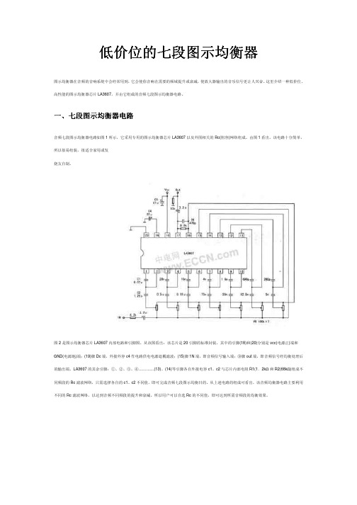
这里介绍一种低价位、高性能的图示均衡器芯片LA3607,并由它组成的音频七段图示均衡器电路。
一、七段图示均衡器电路音频七段图示均衡器电路如图1所示,它采用专用的图示均衡器芯片LA3607以及外围相关的Rc(阻容)网络组成。
由图1看出,该电路十分简单,所以很易组装,很适合家用或发烧友自制。
图2是图示均衡器芯片LA3607内部电路和引脚图。
从该图看出:该芯片是20引脚的标准封装,其中的引脚(18)和(20)分别是vcc(电源正)端和GND(电源地)端;(19)脚Dc端,外接外容c4作电路供电电源退耦滤波;(15)脚1N端,即音频信号输入端;⑩脚out端,即音频信号经均衡处理后的输出端。
LA3607的其余引脚:①、②、③、④…………(13)、(14)等引脚各自外接电容c1、c2与芯片内部电阻R1(1.2kΩ和R2(68kΩ)组成不同频段的Rc滤波网络,只需选择各自的c1、c2不同值,即可完成音频七段图示均衡目的。
从上述电路的组成可看出,该音频均衡器电路主要利用不同的Rc滤波网络,以达到音频不同频段的提升和衰减。
所以用户可以自选Rc的不同值,即可达到所需音频段的均衡效果。
二、七段图示均衡器的设计方法用户设计图1均衡器的Rc滤波网络参数时,只需按下述的方程(1)、(2)计算所需的电容c1和c2。
上式中的R1、R2是已知值,分别为1.2kn和68kΩ该电阻已封装在LA3607的内部见图2。
式中的Q值是Rc(滤波器)电路的Q值(品质因数);fo是由用户对Rc(滤波器)选定的中心频率。
利用上述公式设计各Rc滤波器时,应注意以下两点:1.根据笔者经验,方程(1)式中的Q值,建议取用1.5~2.O之间。
该取值范围,可保证音频在整个频率范围的均衡性能以获得最佳值。
2.方程中的电容器c1、c2应不使用电解电容器。
效果器的使用技巧
效果器的使用技巧效果器是提供各种声场效果的音响周边器材。
原先主要用于录音棚和电影伴音效果的制作,现在已广泛应用现场扩声系统。
无论效果器的品质如何优秀,如果不能掌握其调整技巧,不但无法获得预期的音响效果,而且还会破坏整个系统的音质。
效果器的基本效果类型有声场效果、特殊效果和声源效果三大类。
数字效果一般都储存有几十种或数百种效果类型,有的效果器还有参数均衡、噪声门、激励器和压缩/限幅某功能。
使用者可根据自己的需要选择相应的效果类型。
1.室内声音效果的组成l 直达声:Direction听众直接从声源使播过来获得的声音。
声压级的传播衰减与距离的平方成反比。
即距离增加一倍,声压级减小6dB。
与房间的吸声特性无关。
l 近次反射声(早期反射声)Eary Refections经周围介面一次、二次。
反射后到达听众处的声音。
近次反射声与直达声间的时间延迟为30ms,人的听觉无法分辨出直达声还是近次反射声,只能把它们叠加在一起感受,近次反射声对提高压级和清晰度有益,并与反射介面的吸声特性有关。
l 后期反射声(混响声)比直达声晚到大于30ms的各次反射声称为后期反射声(混响声),混响声可帮助人们辨别房间的封闭空间特性(房间容积的大小)。
对音乐节目来说可增加乐声的丰满度,它在提供优美动听成分的同时并对近次反射声具有掩蔽效应,影响了声音的清晰度和语言的可懂度。
因此这个成分不可没有,也不宜过大。
混响声的大小与周围介面的吸声特性有关,常用混时间RT来表示。
l 混响时间Reverberation Time声源达到稳态,停止发声后,室内声压级衰减0dB所需的时间。
2.声场效果声场效果主要是模仿在不同容积、体形和吸声条件的房间中传播的声音效果。
声场效果的参数主要是:混响时间RT、延迟时间、声音扩散和反射声的密度某参数。
(1)混响时间的调整混响时间的长短,给人以房间体积大小的听音效果。
效果器的混响时间长短可根据下列因素来确定:l 容积较大、吸声不足的房间,效果器的人工混响时间要短。
均衡器的分类
均衡器的分类∙均衡器分为三类:图示均衡器,参量均衡器和房间均衡器。
1.图示均衡器:亦称图表均衡器,通过面板上推拉键的分布,可直观地反映出所调出的均衡补偿曲线,各个频率的提升和衰减情况一目了然,它采用恒定Q值技术,每个频点设有一个推拉电位器,无论提升或衰减某频率,滤波器的频带宽始终不变。
常用的专业图示均衡器则是将20Hz~20kHz的信号分成10段、15段、27段、31段来进行调节。
这样人们根据不同的要求分别选择不同段数的频率均衡器。
一般来说10段均衡器的频率点以倍频程间隔分布,使用在一般场合下,15段均衡器是2/3倍频程均衡器,使用在专业扩声上,31段均衡器是1/3倍频程均衡器,多数有在比较重要的需要精细补偿的场合下,图示均衡器结构简单,直观明了,故在专业音响中应用非常广泛。
2.参量均衡器:亦称参数均衡器,对均衡调节的各种参数都可细致调节的均衡器,多附设在调音台上,但也有独立的参量均衡器,调节的参数内容包括频段、频点、增益和品质因数Q值等,可以美化(包括丑化)和修饰声音,使声音(或音乐)风格更加鲜明突出,丰富多彩达到所需要的艺术效果。
3.房间均衡器,用于调整房间内的频率响应特性曲线的均衡器,由于装饰材料对不同频率的吸收(或反射)量不同以及简正共振的影响造成声染色,所以必须用房间均衡器对由于建声方面的频率缺陷加以客观地补偿调节。
频段分得越细,调节的峰越尖锐,即Q值(品质因数)越高,调节时补偿得越细致,频段分的越粗则调节的峰就比较宽,当声场传输频率特性曲线比较复杂时较难补偿。
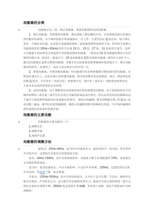
均衡器的主要功能∙均衡器的主要功能有三个:1.调整音色2.调整声场3.抑制声反馈均衡器的调整方法∙超低音:20Hz-40Hz,适当时声音强而有力。
能控制雷声、低音鼓、管风琴和贝司的声音。
过度提升会使音乐变得混浊不清。
低音:40Hz-150Hz,是声音的基础部份,其能量占整个音频能量的70%,是表现音乐风格的重要成份。
适当时,低音张弛得宜,声音丰满柔和,不足时声音单薄,150Hz,过度提升时会使声音发闷,明亮度下降,鼻音增强。
专业均衡器的使用技巧
这篇文章我想同大家交流一下关于专业均衡器的使用技巧。
众所周知均衡器的主要功能就是调整音色、调整声场和抑制声反馈了,如何调整音色的文章很多了,在这里我想着重介绍的是如何使用专业多段图式房间均衡器调整声场和调整声反馈。
现在的专业音响系统中使用的图示均衡器一般都是31段左右,其推拉电位器的Q值是恒定的,一般为1/3倍频程,所以无论是提升或衰减某频率,滤波器的带宽始终是不变的,而频率提升和衰减的程度一般为6-18 dB,最常用的是12dB。
图式均衡器通过面板上推拉键的分布位置,可以非常直观地反映出各频率的提升和衰减情况。
常用的专业图示均衡器频率调节范围一般是20Hz~20kHz,频率调整点一般从低到高分为:20Hz、25Hz、32Hz、40Hz、50Hz、63Hz、80Hz、100Hz、125Hz、160Hz、200Hz、250Hz、315Hz、400Hz、500Hz、630Hz、800Hz、1kHz、1.25kHz、1.6kHz、2kHz、2.5kHz、3.15kHz、4kHz、5kHz、6.3kHz、8kHz、10kHz、12.5kHz、16kHz、20kHz等共31个频点,因其有一项主要功能是用来调整室内声场的,故又称其为:专业多段图式房间均衡器。
下面我就把自己多年来使用均衡器的心得写一下,谨供大家参考:一、使用均衡器调整声场在专业均衡器的三大主要功能当中,调整音色应该是最基本最经常用到的功能了,甚至于目前好多音响师只知道均衡器可以调整音色而不知道专业图式房间均衡器更重要的功能是用来调整声场和抑制声反馈的。
用房间均衡器来调整声场,非常专业的方法是要借助粉红噪声发生器和实时频谱仪来调整。
但我们现在大多数的音响师是不可能有这些设备的,只能就地取材,利用现有的设备想办法进行声场调整了,最简单最实用的办法就是用话筒调节了,其实如何利用话筒来调整声场和调整声反馈也有一些文章介绍过,但我觉得介绍的不够详细或者不够通俗易懂,在多年的工作中,我总结了一套简单、实用、通俗易懂的调整方法,具体调整步骤如下:A首先找一只频响曲线较为平直、频响范围较宽的话筒,最好是电容话筒,也可以是质量比较好的动圈有线、无线话筒。
eq基础
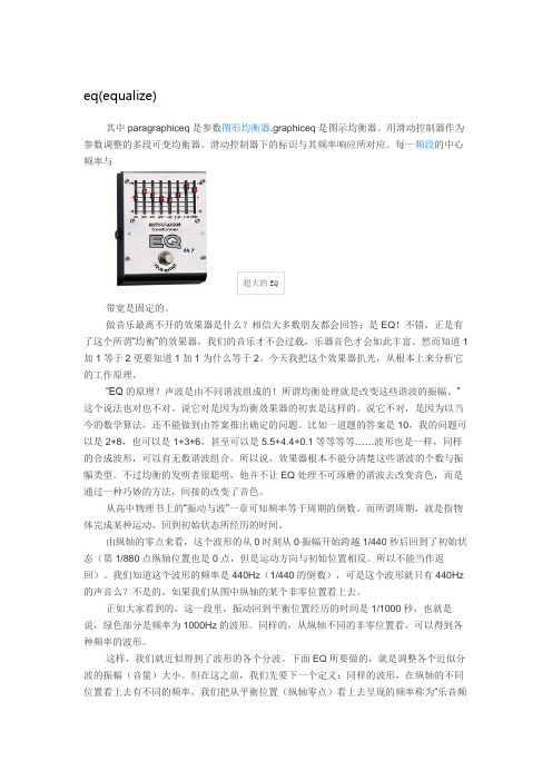
eq(equalize)其中paragraphiceq是参数图形均衡器.graphiceq是图示均衡器。
用滑动控制器作为参数调整的多段可变均衡器。
滑动控制器下的标识与其频率响应所对应。
每一频段的中心频率与超大的EQ带宽是固定的。
做音乐最离不开的效果器是什么?相信大多数朋友都会回答:是EQ!不错,正是有了这个所谓“均衡”的效果器,我们的音乐才不会过载,乐器音色才会如此丰富。
然而知道1加1等于2更要知道1加1为什么等于2。
今天我把这个效果器扒光,从根本上来分析它的工作原理。
“EQ的原理?声波是由不同谐波组成的!所谓均衡处理就是改变这些谐波的振幅。
”这个说法也对也不对。
说它对是因为均衡效果器的初衷是这样的。
说它不对,是因为以当今的数学算法,还不能做到由答案推出确定的问题。
比如一道题的答案是10,我的问题可以是2+8,也可以是1+3+6,甚至可以是5.5+4.4+0.1等等等等……波形也是一样,同样的合成波形,可以有无数谐波组合。
所以说,效果器根本不能分清楚这些谐波的个数与振幅类型。
不过均衡的发明者很聪明,他并不让EQ处理不可琢磨的谐波去改变音色,而是通过一种巧妙的方法,间接的改变了音色。
从高中物理书上的“振动与波”一章可知频率等于周期的倒数。
而所谓周期,就是指物体完成某种运动,回到初始状态所经历的时间。
由纵轴的零点来看,这个波形的从0时刻从0振幅开始跨越1/440秒后回到了初始状态(第1/880点纵轴位置也是0点,但是运动方向与初始位置相反。
所以不能当作返回)。
我们知道这个波形的频率是440Hz(1/440的倒数),可是这个波形就只有440Hz的声音么?不是的。
如果我们从图中纵轴的某个非零位置看上去。
正如大家看到的,这一段里,振动回到平衡位置经历的时间是1/1000秒,也就是说,绿色部分是频率为1000Hz的波形。
同样的,从纵轴不同的非零位置看,可以得到各种频率的波形。
这样,我们就近似得到了波形的各个分波。
十段图示均衡器实验报告

十段图示均衡器实验报告班级:10011107 学号:2011302542 姓名:孔莹莹一、实验目的:均衡器是被广泛应用的音效增强手段,也是实现低音增强、高频补偿、人声清晰度增强等音效的基础。
本作业在实现音频I/O(作业一)的基础上,实现一个具有GUI 界面的十段均衡器小软件,实时对播放音乐进行音效调整。
二、实验要求:本实验要求使用 C/C++语言编程实现一个具有 GUI 界面的图示十段音频均衡器(参考图 3 和演示视频 eq.avi),系统输入为采样率 44.1KHz、单声道的 WAV格式音频文件(如本实验给的 song_mono.wav),输出为经过均衡之后 PCM 数据流,通过声卡播放出来。
通过调整界面上的滑动杆或者选择预设效果,实时调整音效。
三、实验原理:图示均衡器的原理很简单。
图示均衡器由一个低通滤波器,一个高通滤波器和若干带通滤波器并联而成的滤波器组构成。
这些构成均衡器的滤波器中心频率和带宽都是不变的,每个滤波器后接一个增益调节器。
总输出为各个滤波器的加权求和。
用户通过调节每个滤波器的输出增益,来改变均衡器的整体频响。
图示均衡器的整体实现框图,如图2 所示对于10 段图示均衡器,1 倍频程图示均衡器的10 个中心频点为:31.5Hz,63Hz,125Hz,250Hz,500Hz,1000Hz,2000Hz,4000Hz,8000Hz,16000Hz,依据这些频点按倍频程公式计算各个频段的边界频率,然后设计各频段的滤波器,然后级联增益调节器再并接起来就构成了10 段图示均衡器。
采用二阶IIR 带通滤波器级联实现十段图示均衡器。
带通滤波器主要性能指标包括中心频率、带宽、增益、品质因子等,现简介如下:中心频率(CF):通带滤波器功率谱的值达到最大值时对应的频率。
带宽(BW):中心频率两边功率衰减3dB 时,对应的两个不同频率,分别为上、下截止频率,上、下截止频率之差为带宽。
增益(G):均衡器对于各种音效的实现依靠的最重要指标为增益曲线,一般以分贝为单位表示。
图示均衡器的调控

图示均衡器的调控(图)空间对音色的影响很大,所以均衡器就是用来补偿听音环境和改善建筑声频特性的一种仪器。
譬如,一个房间对90HZ频率的声音吸声特别大,则此房间的声频特性在90hz处便有一个低点。
听觉上会感到此点频率附近的声音或成分太弱。
解决的办法就是用均衡器在90HZ处进升提高。
房均的调整按专业来讲。
要借助粉噪发生器和实时频谱仪来调整。
首先将粉红噪声信号输入调音台,调音台输出应为标准电平(OVU)+4dB同时将台上EQ归于0。
开大功放音量听到粉噪信号声,直到粉噪声压级为85dB左右,(用实时频谱仪量),打开实时频谱仪将传声器置于厅堂中心,放到耳平面高。
将实时频谱仪开关置于OCT档,此档为倍频呈滤波器档和粉噪特性对应。
此时实时仪上显示屏显示就是听音环境的频率。
曲线越平,说明建成特性越好。
调整房均器的各点频率,使实时仪上LED显示的频率特性曲线。
显示出来尽量是一条直线。
调完后一般要对均衡器上太过上下悬殊的曲线去一下毛刺。
这样主要是防止调成锯齿状频率特性带来的过大相位失真。
其实在低频(20-50HZ)和高频段(14KHZ以上)的频率特性不必特别强求,如果均衡器调完后出现太明显的峰和谷应该考虑改变房间扬声器的摆放位置。
均衡器调试的好坏直接影响系统会不会出现声反馈,所以在初期一定要耐心调整,不光要用专业设备,更要在实际过程中多注意声反馈现象。
因为均衡器表面旋钮很少,所以我在均衡器部分只介绍两款厂商经典均衡器的技术参数,具体调整请看理论基础。
大家也来说说图示EQ的调节吧,大家对图示均衡器不是很陌生,我想说的是,在所有的周边设备里,图示EQ是最难调的设备,它的应用也很广泛,也希望大家能淡淡自己的精验,也好让大家来学习,有很多人在想,图示EQ的功能就是防止话筒啸叫。
话筒为什么会叫,大家想想,有两个答案,一是系统的电平的增益,二是我们放音场所的频响特性。
图示均衡器曾有人问过我,我的系统为什么在使用图示EQ的时候,话筒还是会叫,这一点值得大家注意,就是系统的电平,有很多音响师在做系统统调的时候,都会把输入通道上的增益开的很大,便PEAK灯不停的亮,为什么这么做呢?这种操作是错误的,想想PEAK这个LED叫什么名子,大家都知道,显示信号的峰值,信号过载的时候这个LED才会亮,那为什么送入调音台的信号的增益要开的那么大呢,没有理由的,我个人认为,也是我的一点精验,在做系统统调的时候,对于话筒信号,对着MIC用最大的力气喊,然后调节GAIN使PEAK亮,然后再衰减0.5db就可以了,对于线路信号,用0db的粉红噪声送入调音台,然后调节GAIN使PEAK灯,然后再衰0.5db就可以了,在调音台的输出电平表上,一定不要超过0db(平均值)峰值更不要超过+4db,这就是音响系统的线性区,只要把信号控制在线性区,系统才工作正常的。
EQ均衡器调节技巧
文:Paul White 编译:闲云孤鹤出处:Sound On Sound 2008年12月频谱的调节是录音和混音中最重要的技能。
我们将解释不同类型的EQ,并且和您共享一些技巧——关于如何更好的在混音中使用它们。
均衡,通常简称为EQ ,是录音,混音中一个关键要素,母带工程师的工具箱,你会听到工程师谈了很长时间如何用EQ做一个特殊的声音,某些型号均衡器的声音特点,例如是如何用均衡去做一个现代化的录音。
但是只是简单的知道工程师Bloggs使用Pultec来处理底鼓,对于为什么要使用Pultec,如何调节却知道的很少。
在本文中,我们会让你了解不同类型的均衡,解释它们的应用。
并且告诉你常用乐器的哪些频段对音色影响最大。
什么是EQ?这个词“均衡”来自电话刚发明的时候,EQ起初用来纠正长距离电话线造成的音调变化,今天它被广泛应用在所有音频设备的“音色”调节功能中。
为了让它非常精确,均衡器增加了频率选择滤波器,能够衰减或提升特定的音频频率。
最简单的均衡器,由一个电容器和一个电阻组成。
随着一系列电阻和电容器的组合,你就会得到一个高切滤波器(有的时候叫做“Top-cut”或“低通”:它们的意思是一样的),你在电吉他上可以找到这样的Tone控制旋钮——可以衰减高频。
把电容器串联和电阻接地将为您提供低切滤波器(或叫做“高通”),削减了较低的频率。
均衡器的响应为6dB/Octave(这意味着在被切除的频段,信号每倍频降低6dB),或称作“First order”。
这些简单的被动式电路不能用来提升频率,它们只能衰减。
为了实现均衡提升,就必须将滤波器和有源电路结合起来,这是彼得.巴克森德尔发明的低音和高音双段均衡器,可以通过2个旋钮衰减或提升低频和高频。
巴克森德尔的基本电路形式成为调音台均衡模块的基础,也是后来大量EQ 插件模拟的基础。
高频和低频让我们更仔细的看看简单的First-Order低切滤波器。
正如我刚才提到的,滤波器的信号电平每倍频程下降6分贝,这意味着低于该频率两个倍频程将衰减12分贝,三个倍频程将衰减18分贝。
均衡器的调整方法使用技巧

均衡器是一种可以分别调节各种频率成分电信号放大量的电子设备,通过对各种不同频率的电信号的调节来补偿扬声器和声场的缺陷,补偿和修饰各种声源及其它特殊作用,一般调音台上的均衡器仅能对高频、中频、低频三段频率电信号分别进行调节。
均衡器分为三类:图示均衡器,参量均衡器和房间均衡器。
1.图示均衡器:亦称图表均衡器,通过面板上推拉键的分布,可直观地反映出所调出的均衡补偿曲线,各个频率的提升和衰减情况一目了然,它采用恒定Q值技术,每个频点设有一个推拉电位器,无论提升或衰减某频率,滤波器的频带宽始终不变。
常用的专业图示均衡器则是将20Hz~20kHz的信号分成10段、15段、27段、31段来进行调节。
这样人们根据不同的要求分别选择不同段数的频率均衡器。
一般来说10段均衡器的频率点以倍频程间隔分布,使用在一般场合下,15段均衡器是2/3倍频程均衡器,使用在专业扩声上,31段均衡器是1/3倍频程均衡器,多数有在比较重要的需要精细补偿的场合下,图示均衡器结构简单,直观明了,故在专业音响中应用非常广泛。
2.参量均衡器:亦称参数均衡器,对均衡调节的各种参数都可细致调节的均衡器,多附设在调音台上,但也有独立的参量均衡器,调节的参数内容包括频段、频点、增益和品质因数Q值等,可以美化(包括丑化)和修饰声音,使声音(或音乐)风格更加鲜明突出,丰富多彩达到所需要的艺术效果。
3.房间均衡器,用于调整房间内的频率响应特性曲线的均衡器,由于装饰材料对不同频率的吸收(或反射)量不同以及简正共振的影响造成声染色,所以必须用房间均衡器对由于建声方面的频率缺陷加以客观地补偿调节。
频段分得越细,调节的峰越尖锐,即Q值(品质因数)越高,调节时补偿得越细致,频段分的越粗则调节的峰就比较宽,当声场传输频率特性曲线比较复杂时较难补偿。
均衡器EQ均衡器1.均衡器的调整方法:超低音:20Hz-40Hz,适当时声音强而有力。
能控制雷声、低音鼓、管风琴和贝司的声音。
常见的均衡器有两种
常见的均衡器有两种,一种是图示均衡器(GRAPHIC EQUALIZER简称GEQ),另一种是参量均衡器(PARAMETRIC EQUALIZER简称PEQ)。
我们先来说图示均衡器:图示均衡器是一种按照一定的规律把全音频20-20000赫兹划分为若干的频段,每个频段对应一个可以对电平进行提升或衰减的滤波器电路,可以根据需要,对输入的音频信号按照特定的频段进行单独的提升或衰减。
图示均衡器最常见的是31段均衡器,也叫1/3倍频程(1/3oct)均衡器。
说到31段均衡,大家都很明白,它是把全音频分成了31个频段,但是这个31段怎样划分或者说1/3倍频程是个什么概念可能就有人不明白了,其实很简单,所谓倍频程就是音乐上所说的八度,1个倍频程就是相隔的两个频率是1倍的关系,比如100赫兹,向上一个倍频是200赫兹,那么100-200赫兹之间的频段就是1个倍频程(音乐上的一个八度)。
这个倍频程的数值,也就是均衡器的每一个滤波器调节范围大小的表示,倍频程值约小,调节范围越小,越精细,反之则相反。
了解了倍频程的概念,再去理解1/3倍频程就不难了。
所谓1/3倍频程,就是把1个倍频程之间的频段再划分为3段,每一段的频带宽度就是1/3倍频程,比如100-200赫兹这一个倍频程,如果分成3段,就成了100-125,125-160,160-200这样三段,所以1/3倍频程的均衡器,它的频点划分就是这样得出来的,从100-200赫兹对应100,125,160,200赫兹4个频点,把这个频段分为三段。
20-20000赫兹,共有10个倍频程,按一个倍频程分成3段来计算,就得出了30段均衡,加上最高的20000赫兹频点,就成为了31段。
了解以上的概念,就不难了解1/2倍频程(15段)均衡和1倍频程(7段或9段)均衡了。
15段均衡就是把一个倍频程分成2段,而7-9段均衡,每一个滤波器负责控制一个倍频程的宽度。
了解了图示均衡器,再来了解参量均衡器就不难了,参量均衡器又是什么呢大家从上面图示均衡器可以了解到,图示均衡器划分的每个频段是固定的,也就是每个滤波器的控制范围是固定的,而参量均衡器首先是一种可以任意改变控制滤波器控制范围的滤波器,同时,对这个滤波器可以控制的中心频率也可以任意设置,然后再进行电平的调整。
音乐音效EQ均衡器调节技巧指南

文:Paul White编译:闲云孤鹤出处:Sound On Sound2008年12月频谱的调节是录音和混音中最重要的技能。
我们将解释不同类型的EQ,并且和您共享一些技巧——关于如何更好的在混音中使用它们。
均衡,通常简称为EQ,是录音,混音中一个关键要素,母带工程师的工具箱,你会听到工程师谈了很长时间如何用EQ做一个特殊的声音,某些型号均衡器的声音特点,例如是如何用均衡去做一个现代化的录音。
但是只是简单的知道工程师Bloggs使用Pultec来处理底鼓,对于为什么要使用Pultec,如何调节却知道的很少。
在本文中,我们会让你了解不同类型的均衡,解释它们的应用。
并且告诉你常用乐器的哪些频段对音色影响最大。
什么是EQ?这个词“均衡”来自电话刚发明的时候,EQ起初用来纠正长距离电话线造成的音调变化,今天它被广泛应用在所有音频设备的“音色”调节功能中。
为了让它非常精确,均衡器增加了频率选择滤波器,能够衰减或提升特定的音频频率。
最简单的均衡器,由一个电容器和一个电阻组成。
随着一系列电阻和电容器的组合,你就会得到一个高切滤波器(有的时候叫做“Top-cut”或“低通”:它们的意思是一样的),你在电吉他上可以找到这样的Tone控制旋钮——可以衰减高频。
把电容器串联和电阻接地将为您提供低切滤波器(或叫做“高通”),削减了较低的频率。
均衡器的响应为6dB/Octave(这意味着在被切除的频段,信号每倍频降低6dB),或称作“First order”。
这些简单的被动式电路不能用来提升频率,它们只能衰减。
为了实现均衡提升,就必须将滤波器和有源电路结合起来,这是彼得.巴克森德尔发明的低音和高音双段均衡器,可以通过2个旋钮衰减或提升低频和高频。
巴克森德尔的基本电路形式成为调音台均衡模块的基础,也是后来大量EQ 插件模拟的基础。
高频和低频让我们更仔细的看看简单的First-Order低切滤波器。
正如我刚才提到的,滤波器的信号电平每倍频程下降6分贝,这意味着低于该频率两个倍频程将衰减12分贝,三个倍频程将衰减18分贝。
- 1、下载文档前请自行甄别文档内容的完整性,平台不提供额外的编辑、内容补充、找答案等附加服务。
- 2、"仅部分预览"的文档,不可在线预览部分如存在完整性等问题,可反馈申请退款(可完整预览的文档不适用该条件!)。
- 3、如文档侵犯您的权益,请联系客服反馈,我们会尽快为您处理(人工客服工作时间:9:00-18:30)。
超低音:20Hz-40Hz,适当时声音强而有力。能控制雷声、低音鼓、管风琴和贝司的声音。过度提升会使音乐变得混浊不清。
低音:40Hz-150Hz,是声音的基础部份,其能量占整个音频能量的70%,是表现音乐风格的重要成份。适当时,低音张弛得宜,声音丰满柔和,不足时声音单薄,150Hz,过度提升时会使声音发闷,明亮度下降,鼻音增强。
平衡悦耳的声音应是:
150Hz以下(低音)应是丰满、柔和而富有弹性;
150Hz-500Hz(中低音)应是浑厚有力百不混浊;
500Hz-5KHz(中高音)应是明亮透彻而不生硬;
5KHz以上(高音)应是纤细,园顺而不尖锐刺耳。
补充回答:
这个跟你的音箱也有一定关系的,有些低音太沉的有些中高音比较多,所以调起来是不一样的,你就用你自己的感觉去调吧,一般年青人慢嗨都是两边向上调,中间向下调,也就是高音和低音加重,中间的减少,象一个开口向上的括号的弧形吧,调好后听起来低音不是那种混浊听不清,高音不剌耳也就差不多了
中高音:2KHz-5KHz,是弦乐的特征音(拉弦乐的弓与弦的摩搡声,弹拔乐的手指触弦的声音某)。不足时声音的穿透力下降,过强时会掩蔽语言音节的识别。
高音:7KHz-8KHz,是影响声音层次感的频率。过度提升会使短笛、长笛声音突出,语言的齿音加重和音色发毛。
极高音:8KHz-10KHz,合适时,三角铁和立*的金属感通透率高,沙钟的节奏清晰可辨。过度提升会使声音不自然,易烧毁高频单元。
2.参量均衡器:亦称参数均衡器,对均衡调节的各种参数都可细致调节的均衡器,多附设在调音台上,但也有独立的参量均衡器,调节的参数内容包括频段、频点、增益和品质因数Q值等,可以美化(包括丑化)和修饰声音,使声音(或音乐)风格更加鲜明突出,丰富多彩达到所需要的艺术效果。
3.房间均衡器,用于调整房间内的频率响应特性曲线的均衡器,由于装饰材料对不同频率的吸收(或反射)量不同以及简正共振的影响造成声染色,所以必须用房间均衡器对由于建声方面的频率缺陷加以客观地补偿调节。
1.图示均衡器:亦称图表均衡器,通过面板上推拉键的分布,可直观地反映出所调出的均衡补偿曲线,各个频率的提升和衰减情况一目了然,它采用恒定Q值技术,每个频点设有一个推拉电位器,无论提升或衰减某频率,滤波器的频带宽始终不变。常用的专业图示均衡器则是将20Hz~20kHz的信号分成10段、15段、27段、31段来进行调节。这样人们根据不同的要求分别选择不同段数的频率均衡器。一般来说10段均衡器的频率点以倍频程间隔分布,使用在一般场合下,15段均衡器是2/3倍频程均衡器,使用在专业扩声上,31段均衡器是1/3倍频程均衡器,多数有在比较重要的需要精细补偿的场合下,图示均衡器结构简单,直观明了,故在专业音响中应用非常广泛。
中低音:150Hz-500Hz,是声音的结构部分,人声位于这个位置,不足时,演唱声会被音乐淹没,声音软而无力,适当提升时会感到浑厚有力,提高声音的力度和响度。提升过度时会使低音变得生硬,300Hz处过度提升3-6dB,如再加上混响,则会严重影响声音的清晰度。
中音:2KHz,包含大多数乐器的低次谐波和泛音,是小军鼓和打击乐器的特征音。适当时声音透彻明亮,不足时声音朦胧。过度提升时会产生类似电话的声音。