Synergy设置指南
Synergy Systems, LLC产品说明书
Oncore Receiver - 1024 Week Roll-Over DatesExcept as noted, all receivers were manufactured by MotorolaDisclaimer – This App-Note was originally created on January 15, 2014 in anticipation of the first 8 channel VP Oncore receivers reaching their internal, 1024 week limit later in that year. Subsequent revisions included additional Motorola Oncore products. During the process of compiling this data, it became clear that the most accurate way to define a specific receiver’s 1024 week roll-over date, is to issue the binary @@Cj Receiver ID Command to the specific receiver of interest and observe the “Software Date.”Add 1024 weeks to that number to derive the roll-over date. In some cases (notes on last page) even the Software Date returned by the @@Cj Receiver message is not always accurate! Summary - The following information was partially derived from the original Motorola Firmware Release App-Notes. If information was not available from Motorola, roll-over dates were determined either by customer inputs or testing of various Oncore receivers in Synergy’s tech-support lab.When it is not possible to query the receiver directly, this App-Note is intended to be used as a guide only for the various Oncore receiver’s roll-over dates. Differences from the listed ”Software Date” in the tables below, have been noticed for Motorola’s internal customers and house accounts (like iDEN and OnStar, etc.) and those who purchased Receivers through domestic and international distributors. In addition, many Oncore receivers have been re-flashed to upgrade receiver features over the years. Those receivers, usually with the letter “R” placed anywhere in the part number, are not included here. Motorola’s published App-Notes did not always include VP, GT, GT+, UT, UT+, M12 and M12+ Oncore firmware “Base Dates” that matched the receiver’s assigned Software Date as shown in the receivers@@Cj ID message. Firmware dates for the GT+ navigation receivers were not always announced in Motorola’s firmware update App Notes, so, where available, the dates listed in the table below are from engineering samples. Because of the above, and some firmware App-Notes not released by Motorola, this Oncore receiver Week Roll-Over information is presented as guide only.Note that an Oncore receiver’s 1024 Week Roll-Over date is completely separate from the NavStar GPS Satellite constellation’s GPS End of Week (EOW) Roll-Over coming on April 6, 2019. A GPS World article on the first, 1999 GPS EOW is here: http://gauss2.gge.unb.ca/gpsworld/gpsworld.november98.pdf. Notes for April 6 2019 are here: https:///cgsic/meetings/2017/powers.pdf and here: https:///sites/default/files/documents/Memorandum_on_GPS_2019.pdfMotorola either did not test, or did not disseminate test results for distribution, on any of the PVT-6, Basic, VP, UT\UT+, GT\GT+ or M12+ receivers for the April 2019 GPS End of Week roll-over.Details - All Motorola Oncore series GPS receivers, contain an internal, 1024 week counter that is based on the receiver’s firmware compile date. A receiver’s“Software Date,” as displayed in the receiver’s@@Cj ID Message, were defined by Motorola’s software engineering staff. The Software Date, starting on row 6 column 16 of the below Receiver ID matrix, should reflect the firmware’s final compile date from which a week roll-over date can be calculated but deviations from this standard have been noted.© Synergy Systems, LLC 2008 - 2019 All rights reserved.SynPaQ® and Time Proven Products and Support® are registered trademarks of Synergy Systems, LLCAn example of firmware date confusion can be seen with UT+ v3.2. The observed “Software Date” on a Synergy sample using the @@Cj Receiver ID command, shows 8/23/2000 but Motorola’s “Oncore Technical Application Note” says the Default year changed to 1/1/2000. Issuing the @@Cj Receiver ID Command to the specific receiver of interest is the only reliable way to determine the 1024 week roll-over date. Always believe the receiver being tested!As stated above, the best method of determining a receiver’s actual 1024-week roll-over date is to use the @@Cj Receiver ID command and observe the response. Add 1024 weeks to the observed date to reveal the receiver’s 1024 Week Roll-Over date. A simple to use date Calculator is here:https:///date/dateadded.html?m1=8&d1=1&y1=2000&type=add&ay=&am=&aw =1024&ad=&rec=OEM receivers later than the PVT-6, Basic Oncore and VP Oncore (i.e. GT+, UT+, M12+) do not have the capability of permanently setting the base year date (epoch) due to the lack of on-board, non-volatile flash memory. Review the individual Oncore receiver Firmware Release Notes for details here:/support/motorola-legacy-products/An estimated Roll-Over date is used (below) when a publish date and\or a physical GPS board sample was not available to test. Here are the Oncore GPS Receiver Week Roll-Over dates reported by the Motorola App Note, the @@Cj message, and Synergy or customer Oncore receiver engineering samples:© Synergy Systems, LLC 2008 - 2019 All rights reserved.SynPaQ® and Time Proven Products and Support® are registered trademarks of Synergy Systems, LLC2. Motorola’s Firmware Note for the GT+ v2.2 firmware update lists a Default Date of January 1, 1998 but the Motorola Firmware App-Note is dated much later at “8/98” giving a low confidence that the roll-over date is correct.© Synergy Systems, LLC 2008 - 2019 All rights reserved.SynPaQ® and Time Proven Products and Support® are registered trademarks of Synergy Systems, LLC** Motorola Firmware App Note incorrectly published 3/1999e = If no firmware date published, or available from a test sample, an estimate based on the first day ofthe Release Note month (which may be off by +/- a couple of months!).Firmware v1.7 marked the beginning of the M12+ Series receivers (there was not an M12 receiver with v1.7). Unfortunately, Motorola did not make a distinction between the M12 and M12+ receivers in their “M12 Oncore Firmware Version History” App-Note:/wp-content/uploads/2018/11/m12-nav-firmware-history-v1.5.pdf Notes: 1. Other, commercially released, Motorola Oncore OEM GPS timing receivers, withdifferent version numbers and firmware dates, were produced between 1992 and 2005. Those special part numbers were reserved for Motorola’s internal automotive group, Motorola’s iDEN cellular products group and volume customers such as GM OnStar. Because firmware for these products was customized for the application, the firmware dates will not match those above.2. Some of Motorola’s volume receiver users were assigned special receiver and firmware partnumbers for VP, UT+, M12 and M12+ Oncore Navigation or Timing receivers. The 1024 WeekRoll-Over for those receivers must be calculated using the firmware date reported in the @@Cj message. Motorola either did not test, or did not publish a test for distribution, on any of the VP, UT\UT+, GT\GT+ or M12+ receivers for the April 2019 GPS End of Week roll-over.A Work-Around for Oncore receivers past their 1024 week - (a) With the receiver powered off, disconnect the GPS antenna (b) power-on the receiver and set the date and time (for PVT-6 and VP Oncore models the receiver must be in idle mode and the @@Ab GMT offset set first) (c) Connect the GPS antenna (set the PVT-6 and VP Oncore receivers to Fix Mode) and allow the receiver to acquire a 3-D fix and download an Almanac (about 13 minutes). The time and date should now be correct. Follow this procedure every time the receiver is power-cycled.© Synergy Systems, LLC 2008 - 2019 All rights reserved.SynPaQ® and Time Proven Products and Support® are registered trademarks of Synergy Systems, LLCInformation in the tables above is based on several sources thought to be reliable but not guaranteed in any way: (1) Motorola firmware release notes were noted for the various Oncore GPS receivers (2) Observed firmware dates were derived from engineering samples at Synergy or (3) supplied by customers.Firmware Release Notes do not reflect the actual software date unless specifically mentioned in the note itself. In some cases, the VP Oncore engineering samples made available for this study may have been re-flashed and may contain a Firmware Date other than the original date established at the factory.In collating the above information, Synergy has reviewed Mot orola’s documentation made available as App-Notes and Firmware Release Notes received from a period of 1992 through 2005. Many of he GT+ Oncore firmware dates were not included in Motorola’s release Notes.If users of Motorola’s legacy receivers have accurate firmware roll-over dates for any of the above receivers, please forward it to*********************** for inclusion in this App Note.iLotus M12M Oncore 12 channel GPS ReceiversThe first timing and navigation boards produced by iLotus were RoHS 5 of 6. In 2007, iLotus started producing RoHS 6 of 6 timing and navigation boards with different part numbers as shown below. The firmware dates were the same for both 5 of 6 and 6 of 6 models.the M12M receivers were tested by iLotus in 2013 for the GPS Satellite System End of Week (EOW) April 2019 Week Rollover (different from the subject of GPS receiver week roll-over discussed above). They performed normally as expected with no user intervention. Please request iLotus M12M GPS End of**********************************************.iLotus M12M Oncore GPS receivers – The first timing and navigation boards produced in 2006 by iLotus were RoHS 5 of 6. In 2007, iLotus started producing RoHS 6 of 6 timing and navigation boards with different part numbers (shown above). Firmware dates were the same for both 5 of 6 and 6 of 6 models. Historical Note - Synergy’s distribution contract with Motorola was terminated when their GPS Division was sold in June of 2005 to two entities. The navigation portion went to Continental in Germany and the timing part went to SiRF Technologies in San Jose, CA. Motorola selected iLotus of Singapore, an approved CM for Motorola products, to produce their new M12M GPS receiver for use by other Motorola Divisions and to Synergy Systems, LLC for general distribution.© Synergy Systems, LLC 2008 - 2019 All rights reserved.SynPaQ® and Time Proven Products and Support® are registered trademarks of Synergy Systems, LLCIn the intervening years, Synergy has provided continued support including technical assistance for migrating to the Motorola designed M12M GPS receivers produced by iLotus, and Synergy’s SSR Series Multi-GNSS boards. End of life and transition support has included top level testing of various receivers for the NavStar Constellation’s April 6, 2019 GPS End of Week (EOW) Roll-Over but not for confirmation of the roll-over dates of the individual receivers (PVT-6, VP, GT\GT+, UT\UT+, M12\M12+) as outlined in this App-Note.Additional, more in-depth receiver testing is available when required from testing agencies with satellite simulators. For example, testing of specific receiver parameters like confirming exact GPS receiver roll-over dates (when Motorola documentation is not sufficient). In those cases, we recommend contacting our engineering partner of twenty years, Rick Hambly at CNS Systems Inc. .Rick, an expert in precision timing applications, has provided versions of his CNS Clocks to the world-wide radio astronomy community, NASA and others for over twenty years. He can be contacted at (410) 987-7835 or *************** for a discussion of test needs and a quotation for testing work.Note - 2 March 2019 - Motorola’s “Oncore Technical Application Note” for UT+ firmware release v3.2 dated 10/2/2000 incorrectly noted item 3 “Default year changed to 1/1/2000. the actual year, as indicated by several UT+ GPS receiver samples is August 23, 2000. The UT+ section of the week roll-over table above has been corrected for the UT+ with v3.2 firmware. The actual roll-over date will be 8 April 2020.10 March 2019 – Added CNS Systems, Inc. as a source for additional receiver testing and consultation 15 March 2019 – Added (1) the roll-over date of January 11, 2019 for the UT+ model numberR5xxxUxxx4 with v3.1 firmware. (2) roll-over date of February 26, 2015 for the XT Oncore model number A1xxxxBxx5. (3) roll-over date of February 26, 2015 for the VP\B4 Oncore model number B4xxxPxxx5. 16 March 2019 – Recent testing indicated that even the “normally reliable” @@Cj Receiver ID message does not always return a Software Date that coincides with Motorola’s published material or the information in the @@Cj Receiver ID message itself. For example, this UT+ receiver should have rolled-over in August of 2018 but it is still working normally as of March 14, 2019:Added two more links for explanation of the NavStar GPS Satellite constellation’s GPS End of Week (EOW) Roll-Over coming on April 6, 2019© Synergy Systems, LLC 2008 - 2019 All rights reserved.SynPaQ® and Time Proven Products and Support® are registered trademarks of Synergy Systems, LLC。
鼠标键盘共享工具Synergy的使用方法图文教程

鼠标键盘共享工具Synergy的使用方法图文教程Synergy允许你轻松地在你办公桌上多台计算机之间共享你的鼠标和键盘,它免费并且开放源代码。
你只要将鼠标(指针)从一台计算机的屏幕边缘移出到另一个屏幕就行了。
甚至可以共享你的剪贴板。
你所需要的仅仅是一个网络连接。
Synergy是跨平台的(可以运行于Windows,Mac OS X和Linux)。
先介绍本人机器环境,机器两台,Windows 7 x64, Ubuntu 12.10 x64.由于工作中需要使用Windows查看邮件,故使用Windows 7作为主机。
Server端配置在 Windows 上安装 Synergy ,不多说了,电脑,主界面如下。
主界面上点击Configure Server。
从右上角拖拽到网格上,双击配置,最多可以配置15个。
然后点击Start运行serverClient配置Ubuntu源里有,电脑技术,直接安装:1sudo apt-get install synergy同时建议安装quicksynergy,synergy的GUI工具1sudo apt-get install quicksynergy运行quicksynergy,在Server hostname/IP address 中填入server 的 IP 或 hostname ,建议使用 hostname.点击 Execute 执行。
注意两个名字都需要在 Server 端配置。
Ubuntu开机自启动在Startup Application Perferences中加入如下配置。
具体参数可以man之。
如果成功连上的话,server端的log中会有类似信息:1NOTE: accepted client connection2NOTE: client "TELENAV-90171" has connected效果如图:(责任编辑:admin)。
SDL Trados 2007 版本说明
SDL Trados 2007 版本说明此版本说明包含与此版本相关的最新信息。
SDL强烈建议您在开始使用SDL Trados 2007及其应用程序之前通读此版本说明。
版权(c)2005-2008 SDL plc.版权所有。
版权(c)1990-2005 SDL plc.SDL Trados 2007 相关信息此版本的整套SDL Trados应用程序在很多新功能方面有所增强。
SDL Trados 2007开始菜单组中的“SDL Trados 2007新增内容”教程,以及“SDL Trados 2007用户指南”都对此有更加详细的描述。
SDL Trados 2007须在软许可证下使用。
关于软键许可证的工作机制以及如何得到并安装软键许可证的详细信息,见SDL Trados 2007安装指南中的许可证章节,也可参考网站上SDL支持中心提供的信息。
软件SDL Trados 2007仅依照现状提供使用。
用户使用SDL Trados 2007时自负风险。
对于用户使用SDL Trados 2007产生的任何损失,SDL不承担任何责任。
SDL Trados 2007新增功能∙最新的项目管理自动化应用程序SDL Trados Synergy 2007与SDL Trados 2007集成。
Synergy 程序为SDL Trados 提供了项目创建和管理的工具。
通过Synergy,用户可以快捷地创建和分配项目,并且可以实时跟踪项目进程。
项目组成员使用SDL Trados翻译工具对项目文件进行操作,同时可以轻易共享项目资源,如在线翻译记忆。
关于此版本中SDL Trados Synergy及其新增功能的更多信息,请在SDL Trados 2007中查看“SDL Trados Synergy用户指南”SDL Trados Synergy支持微软Office 2007格式:DOCX (Word 2007),PPTX (PowerPoint 2007) 和XLSX (Excel 2007) SDL Trados 和SDLX 2007都支持这些格式,同时一如继往地支持微软Office 2003、XP (2002)和2000。
Somfy 屏幕驱动器 Maestria 50 RTS 设置指南说明书

BEFORE YOU BEGINMotors are shipped in FACTORY MODE without limit settings and thetransmitter ID’s. Power must ONLY be connected to current screenbeing programmed. All other screens must be disconnected fromtheir respective power while programming.Note - If motor is 120V AC hardwired and cannot be disconnected, please contact an electrician prior to calling Somfy customer servicefor assistance.CONNECT TO POWER MODEWith the motor installed in the screen, connect power to the motor (120V AC).MAESTRIA™ 50 RTS MOTORSWhile programming, screens should not be inactive for longer than 2 minutes or motor will exit PROGRAMMING MODE.INITIATE PROGRAMMINGOn the transmitter, press and hold bothUP and DOWN simultaneously until thescreen jogs.Side View50mm motor diameterCHECK THE DIRECTION OF OPERATIONIf hand-held transmitter direction is not properly programmed,Eolis/Soliris RTS sensor will not function in the manner it wasintended. Damage to the screens and injury may occur as a result. Check the direction of rotation by pressingUP or DOWN.If necessary change the direction of rotationby simply pressing and holding the MYbutton until the screen jogs.AUTOMATIC ADJUSTMENT OF THE LIMITS1) Bring the screen to its half-way position.2) Briefly press UP and DOWN simultaneously:the screen jogs.3) Press the DOWN button:the screen lowers until itdetects the LOWER Limit,performs a brief upwardmovement and returns toits LOWER Limit position.4) To validate the setting, press MY untilIf the lower end limit is not set automatically a er several attempts,restart the setting and perform the step on the following page.MAESTRIA™ 50 RTS MOTORSPROGRAMMING MODE MANUAL ADJUSTMENT OF THE UPPER END LIMIT AND THELOWER END LIMIT1) Position the screen at the desired UPPER Limit 2) Press MY and DOWN simultaneously:the screen lowers.3) Position the screen at the desired LOWER Limit.4) Press MY and UP simultaneously: the screen raises.5) Press MY until the screen jogs tovalidate the end limit setting.1 sec.MANUAL ADJUSTMENT OF THE LOWER END LIMIT AND AUTOMATIC ADJUSTMENT OF THE UPPER END LIMIT1) Position the screen at the desiredLOWER Limit.4) Press MY and UP simultaneously:the screen raises.5) Press MY to stop the screen.6) Press MY until the screen jogs tovalidate the LOWER Limit setting.A er pressing MY, the UPPER Limit is set automatically.MANUAL ADJUSTMENT OF THE LOWER END LIMIT AND AUTOMATIC ADJUSTMENT OF THE UPPER END LIMIT WITH AUTOMATIC CATCHING SYSTEM LOCK SYSTEMThe catching system at the lower end limit may vary depending on the driven product, but the procedure for setting the entrance/exit positions of the catches remains the same on all systems.1) Starting from half-way position press and holdUP and DOWN simultaneously for 5 secondsuntil a slow up and down movement.2) Press the DOWN button: the screen lowers.3) Press the MY button to stop the screen at position (P1), which corresponds to the automatic catching system's entrance point.4) Press MY and UP simultaneously:the screen raises and stops,putting tension on the fabric.MAESTRIA™ 50 RTS MOTORS 5 sec.6) Press the DOWN button: the screen lowers.7) Press the MY button to stop the screen at position (P2), which corresponds to the automatic catching system's exit point.8) Press MY until the screen jogsto validate the end limit setting.MAESTRIA™ 50 RTS MOTORSMANUAL ADJUSTMENT OF END LIMITS WITH THE AUTOMATIC CATCHING SYSTEMThe catching system at the lower end limit may vary depending on the screen product, but the procedure for setting the entrance/exit positions of the catches remains the same on all systems.1) Starting from half-way position press and holdUP and DOWN simultaneously for 5 secondsuntil it jogs.3) Press the UP button: the screen raises.4) Press MY to stop the screen at the UPPER Limit(adjust if necessary).5) Press MY and DOWN simultaneously: the screen lowers.6) Press the MY button to stop the screen atposition (P1), which correspondsto the automatic catching system's entrance point. 5 sec.MAESTRIA™ 50 RTS MOTORSUSER MODEADJUSTING THE LIMITS IN USER MODEPROGRAMMING OF A NON PRE PROGRAMMED CONTROL POINT1) Switch off the power supply (the pre-programmed transmitter is deleted).2) Switch the main power supply back on. The screen jogs.3) Simultaneously press the UP and DOWNbuttons of the control to be programmeduntil the screen jogs.4) Briefly press the PROG button of this control:the screen jogs; the control is programmed.7) Press MY and UP simultaneously:the screen raises and stops, puttingtension on the fabric.8) Press the DOWN button:the screen lowers.9) Press the MY button to stop the screenat position (P2), which corresponds tothe automatic catching system's exit point.10) Press MY until the screen jogsto validate the end limit setting.MAESTRIA™ 50 RTS MOTORSOBSTACLE DETECTIONCHOICE OF THE LEVEL OF DETECTIONThis function gives the possibility to adjust the obstacle detection during the downward movement to deactivate it or adjust the sensitivity.1) Starting from the screen in half-way position, press MY and UP briefly and again MY and UP for 2 seconds. The screen jogs.2) Within 10 seconds press UP or DOWN to change the level of detection. (without feedback within 10 seconds the actuator goes back to USER MODE. Go back to Step 1.)ESD level 0: the obstacle detection is more sensitive.The screen moves up and down slowly.ESD level 1: (DEFAULT) - the obstacle detectionis reliable on most zip screens. The screen jogs.ESD level 2: the obstacle detection is deactivated.The screens moves up and down slowly.3) Press MY for 2 seconds to validate the setting.The screen jogs. 2 sec.2 sec.Slow jogSlow jogShort jog。
依诺肝素在循证医学中的新证据
依诺肝素在循证医学中的新证据大量的循证医学证据表明,近10年来,急性冠脉综合征(ACS)治疗进展非常迅速,尤其是已经确立了低分子量肝素(LMWH)在ACS抗血栓治疗中的重要地位。
最初的研究侧重于探讨LMWH和阿司匹林联合应用治疗不稳定型心绞痛(UA)及非ST段抬高心梗(NSTEMI)。
后续研究如近期公布的SYNRGY,又使我们对如何联合应用LMWH和GPⅡb/Ⅲa受体拮抗剂有了更深入的认识。
LMWH种类很多,关于依诺肝素的大规模临床研究最多。
ESSENCE和TIMI11B研究ESSENCE和TIMI11B研究比较了依诺肝素和普通肝素的临床治疗效果。
结果显示,与使用普通肝素相比,发病初期未施行冠脉介入治疗的UA/NSTEMI患者在使用依诺肝素后,其联合终点(死亡、心梗、顽固性心绞痛)发生率显著降低。
TESSMA是对前瞻性设计的ESSENCE和TIMI11B的荟萃分析,结果表明,发病后第2天至第43天内,依诺肝素组的死亡和非致死性心梗联合终点事件下降约20%,也就是说依诺肝素治疗可以降低病死率,同时并不增加出血危险,仅穿刺部位皮下淤血略有增加。
基于以上试验和其他临床试验研究结果,2002年ACC/AHA的UA患者诊治指南认为“对UA/NSTEMI患者,除非计划24小时内实施CABG,作为抗凝剂,依诺肝素优于普通肝素。
”由于当时关于GPⅡb/Ⅲa受体拮抗剂与依诺肝素联合抗凝的关键性试验正在进行中,对于两者联用的安全性、有效性仍然存在疑问。
ACUTEⅡ研究ACUTEⅡ是一项关于依诺肝素和普通肝素的随机、双盲、对照研究,共入选525例UA/NSTEMI患者,均联用噻氯匹啶,主要研究依诺肝素的安全性,尤其是服用药物后最初24小时内TIMI出血评价。
结果表明,两组患者出血发生率、血小板减少发生率相似,但依诺肝素组30天缺血事件发生率有减少趋势,而再发心绞痛或因UA再住院者明显少于普通肝素组。
AtoZ和INTERACT研究AtoZ研究进一步探讨依诺肝素和噻氯匹啶联合治疗问题。
Elekta Synergy开关机步骤及注意事项
Elekta Synergy开关机步骤及注意事项一、开机前准备进入机房之前,开启机房送风、排风风机;开启操作室、服务器和机房空调。
注意:⑴服务器房间空调不能关闭,必须常开制冷20℃。
⑵加速器机房设备间空调在开机期间,必须常开制冷20℃。
二、开机1、开机顺序:2、开加速器主机箱电源,等待加速器启动之后,进入机房按手控盒上的Reset Motor,才能启动机器运动部分。
3、主机启动之后,再开启MOSAIQ、XVI和iViewGT主机电源,可避免链接出错。
使用时,用操作者各自账户、密码登录。
4、加速器全部开启之后,需要进行预热。
从低档能量开始,使用低剂量率(300MU/min)出束,晨检正常后才可治疗。
三、使用加速器注意事项1、使用限光筒时,注意不要碰撞机头上的十字丝薄膜,此膜易损伤,注意保护。
2、使用XVI时,需要先将iViewGT探测板打开,方可打开XVI探测板。
3、XVI和iViewGT探测板板面均设有连锁,碰撞探测板即出Interlock,使用需注意。
4、如遇紧急情况,切莫惊慌,按红色急停开关,然后处理病患,再报请相关人员处理。
5、如遇机器故障,上报科室工程师或厂家工程师处理。
四、关机1、先关闭MOSAIQ、XVI和iViewGT,再关闭机器主机。
关闭时,只需按常规电脑正常关机方式,退出打开程序,然后关闭电脑即可。
2、关机顺序:3、关主机时,若早上提醒备份,则报物理师进行备份。
注意:⑴XVI和iViewGT在关闭时,需要转换显示器,确认已经两者都关闭成功。
SYNERGY_入门
SYN ERGY 入门下面具体介绍使用Synergy 1 ^0 p; C( R* h7 B3 s2 D9 h) Q+ W 界面简介使用列表视图2 t" E" ^)r' T! Y,m- O,n s设置选项收藏分享评分回复引用订阅 TOP管理员2#admin发表于 2009-4-14 18:23 | 只看该作者使用 SYNERGYSynergy 客户端允许您创建本地化项目,将这些项目发送至本地和远程小组成员并将其收回。
您可以在Synergy Server 上跟踪项目。
项目跟踪使您可以看到谁正在处理文件以及文件已达到哪一本地化流程阶段(例如,已翻译或已检查)。
Synergy 客户可通过 Intranet(通过 LAN 或 WAN)或 Internet 访问Synergy Server。
; l3 O1 b- I* m% K/ {+ M/ H( ]9 x) v有关 Synergy 和 Synergy 项目的概述,请参见《SDL Trados Synergy 指南》。
您可以从 Synergy% d; }( |& f, N5 ~8 C) r中的“开始”视图访问该指南。
访问 Synergy* u% ]% P* U* X: K0 q要访问 Synergy 客户端应用程序,请转至开始 > 程序 > SDL Trados Synergy 2007。
您还可以从SDL Trados 菜单访问 Synergy(开始 > 程序 > SDL International > SDL Trados 2007 > Synergy)。
默认情况下,Synergy 可在“开始”视图中打开。
( f% ?* u: l$ `( _$ d真的不掉线吗??、????????????注:您还可以将 Synergy 设置为打开时显示“今天”视图或“项目”视图。
回复引用TOP管理员3#admin发表于 2009-4-14 18:25 | 只看该作者界面简介% k$ p* L6 U- m/ B( i Synergy 界面由以下组件构成:9 ~% Z# M7 l/ p: Z' ^" g- v菜单栏–显示项目、文件、查看、报告和帮助菜单。
Synctoy操作指南

Synctoy操作指南在部分系统规划中,需要实现资料夹的同步,这时我们就考虑使用Microsoft同步工具SyncToy,配合Windows自带的计划任务。
这次将以一个案例来对两台服务器中存放ASP站点程序的文件夹进行自动同步。
SyncToy是微软在2005年10月发布的,该工具现在的版本为1.4,发布日期为2006年10月30日,是一款用于Windows XP/2003操作系统上免费的、易于使用的同步工具。
它提供了简洁的操作界面、简单的使用方法和高度的自定义功能,可以帮助我们从繁重的拷贝、移动及同步不同目录的工作中解脱出来,仅仅根据需要单击几次鼠标进行设置,就能搞定更多的操作,也会有额外的自定义功能而不会增加使用的复杂程度。
SyncToy 不仅可以同时管理多个目录系列,还能够合并两个目录里文件为一个目录等,最大程度上提高了IT工程师的工作效率。
下面,我将详细的对如何使用该工具做一说明。
一、服务器说明:二、安装SyncToy:SyncToy下载地址:/downloa ...&displaylang=enSyncToy v1.4工具大小:971KB安装要求:安装之前须安装 Frameworks默认安装路径:C:\Documents and Settings\Administrator\Local Settings\Application Data\SyncToy在本次运用中,将SyncToy安装在10.134.130.104中。
安装完成后看到的SyncToy运行界面如图一。
三、使用SyncToy:安装完成SyncToy后,开始进行同步资料夹设置。
点击主界面下方的“Create New Folder Pair”按钮创建一对新的操作目录,程序弹出如图二的窗口。
在这个窗口的标题栏中我们可以看到操作一共分为四个步骤,操作上非常简便。
点击“Left Folder”下的“Browse”按钮,选择左目录的路径。
SYNERGYchange操作手册

SYNERGY/Change 用户操作手册1.环境说明本文旨在描述使用SYNERGY / Change所进行的一些常用基本操作。
安徽移动BOSS网络中的SYNERGY/Change的服务器IP为:10.147.134.9,WEB访问端口为8600。
2.用户登陆用户通过访问http://10.147.134.9:8600,可连接到Change。
输入User Name及Password(默认password为password), Database共有三个库可供选择,‘testdb’为开发科用户进行有关练习使用的数据库, ‘boss15’为正式使用的数据库,‘tut64a’为流程定置开发使用的数据库。
用户请使用‘boss15’或‘testdb’数据库登陆。
Role分为’User’,’Admin’及’RsportBuilder’三种,‘Admin’, ’ReportBuilder’是用来对系统进行设置的角色,只有管理员才拥有的它们的登陆权限,作为普通用户请使用’User’角色登陆。
3.修改用户信息登陆后用户可以对自己的个人信息进行修改。
在菜单栏中选“Settings”。
3.1. 修改用户信息3.1.1.修改个人信息选择‘Profile’选项卡,再下面‘General’中添加或修改你的个人信息,其中包括:‘E-mail’,‘Phone’,‘Campany’,‘Fax’,‘Address’等。
修改完之后,请点击‘Update’。
3.1.2.修改用户密码同样选择‘Profile’选项卡,再下面‘Change Password’中修改你的用户登陆密码。
修改完之后,请点击‘Update’。
3.2. 修改用户的常规设置选择‘General Peferences’选项卡,其中可以更改用户的常规设置。
其中包括:1.‘Home Page’系统显示的默认主页,2.‘Default Font Size’默认字体尺寸,3.‘Default Object Scope’默认活动范围,4.‘Default Submit Form’默认的提交类型5.‘Show in CR Log’选择在CR日志中显示的项可将其进行修改从而更改个人用户的一些默认值。
Synergy IPRO3100 20KVA中文用户手册-ATLAS ASIA LTD
版本号: 01
《Synergy 系列 UPS 用户手册》是关于 UPS 安装和操作的单一信息来源。操作 UPS 前请通读本 手册。 在连接电源前必须研究本手册。必须由具有电气设备安装经验的合格技术人员进行连接。 本手册提供有关于不间断电源系统 (UPS)的安装、启动和操作的信息。
目录
1 简介............................................................................................................................................................... 1 2 操作和维护期间的安全指示.............................................................................................................................. 2
1.0 概 述 ................................................................................................................................................ 2 2.0 安全建议 ........................................................................................................................................ 2 3.0 电 击 ................................................................................................................................................ 2 4.0 安全警告 ........................................................................................................................................ 2 5.0 电 池 的 安 全 预 防 措 施 .................................................................................................................. 3 6.0 处理电池 ........................................................................................................................................ 3
OpenManage Network Manager 虚拟设备安装指南说明书

:In This Document :>Virtual Appliance Installation GuideInstalling the OpenManage Network Manager Virtual Appliance – 2Virtual Appliance Quick Start – 2Start the Virtual Machine – 6Start the Application – 7The Application is Ready to Use - What’s Next? – 8Upgrding the VM – 92Virtual Appliance Installation GuideInstalling the OpenManage Network Manager Virtual ApplianceThe OpenManage Network Manager Virtual Appliance, or virtual machine (VM)is a single .ova file, which comes from a Vsphere 4.0 client. Although thisshould compatible with products listed below, only the VMware® player 8,Vmware Workstation 8 and Vsphere ESX®4.1 have been evaluated. Other poten-tially compatible players:.x• ESX®5.0• Fusion 4.0• Fusion 5.0• Workstation 8.0• Workstation 9.0This document assumes in depth Linux and VMware® Administration knowledge.The following assumes that the VM is a standalone server and client access comesfrom a client browser from another host. If you need client access directly on theVM, you must install a compatible browser on the VM.For best experience and use of time, trial users should allocate sufficient resourcesduring the trial period so they can evaluate the full set of features. We encourageusers, to use the many resources available.Refer to the hardware requirements for a conventional installation (Best Practices:Single Server Hardware of the Installation Guide) for more about resource require-ments. You may also get additional information, videos and access to supportand a knowledgebase at the website where you downloaded this appliance. Youcan also install OpenManage Network Manager directly onto a physical Windowsor Linux server. The full packaged software is available on the same web sitewhere you got the VM.You may deploy the OpenManage Network Manager Trial VM as virtual applianceon a VMware® or ESX® host. This guide shows how to configure it as a virtualappliance. The instructions assume you have already installed and configured theESX® host or VMware® host. For additional information about installing andconfiguring the ESX® virtual host machine, consult your VMware® documenta-tion.Virtual Appliance Quick StartIt is recommended that you read this entire guide before installation. Here are thequick start steps:1.Import the .OVA file and power on.2.Start the VM and login with user= synergy password=synergyP@$$3.Run ./setup command and select Option #1 for initial VM configuration.4.After restarting the VM, go to ./setup menu and run the "Check server statusoption” to confirm server startup status.3ing a remote browser go to url http://<yourIP>:8080 and logion withusername=admin, password=adminThe following section will provide more details for installation of the VM.Configure OpenManage Network Manager as a Virtual ApplianceTo configure OpenManage Network Manager as a virtual appliance, follow thesteps below. Details about each step follow this list.1.Prerequisites2.Deploy the OVA Template3.Start the Virtual Machine4.Initial VM Host Configuration5.Start the Application6.Start the Application7.Connect the Client Browser8.The Application is Ready to Use - What’s Next?PrerequisitesMake sure you have the following:• A downloaded OpenManage Network Manager.ova file• An IPv4 address has been identified for the VM appliance• The VM host must have a connectivity to the target managed devices.• Neither Firewalls nor other restrictions block communication for ICMP,SNMP, FTP, TFTP, SCP, SSH, Telnet, HTTP.• SMTP and internet access are required for notification from OpenManageNetwork Manager by e-mail as well as for license/subscription renewalVM constraintsThe VM is intended and sized to support trial/evaluation of OpenManage Net-work Manager Software for 25 devices. Other deployments may be supported butmay require additional VM re-configuration. Many factors affect the VM perfor-mance. The underlying hardware resources must be able to support the desireddeployment configuration. Re-configuration may require more RAM, Hard drives,faster hard drives, CPU/Cores or storage allocated to the VM. Please refer to thesizing section of the User Guide for details.This VM has these configuration limits based on VM export compatibility set-tings:• 64 GB memory limit• 8 processor limit• 10 network adapter limit• 2 TB disk size limit4Virtual Appliance Installation GuideHardware Requirements• The host machine has a minimum of 4 cores that can be allocated to the VM• CPU speed should exceed 3.0 Ghz• The host machine has a minimum of 10 GB RAM that can be allocated to theVM• The host machine has at least 120 GB disk space that can be allocated to theVM. The OMNM VM is pre-set to installation defaults and will dynamicallygrow up to 100 GB. If the VM will be used beyond a trial evaluation, you mayneed more space depending on you specific usage and needs. Consult yourVM and /or Linux administrator to modify the OMNM VM.The trial VM has been configured for 10 GB RAM. Best practice is to allocate theVM 12 GB (or more).For better performance the database should consist of 1 or more 10-15K RPMdisk, or the equivalent solid state disk.If you plan to use the VM beyond the initial trial configuration, consider someconfiguration changes. Refer to the User Guide for sizing recommendations beforeconverting the trial VM to a production usage. You may need to do the following:• Expand the storage capacity to accommodate the workload data and reten-tion preferences.• Allocate additional memory to support a production environment• Ensure the VMware® virtual disk runs on adequately performing physicaldisk infrastructure. Heavy performance monitoring and TFA requires disk IOspeeds that support this configuration.Again: Refer to the product User Guide before converting the trial VM to a produc-tion usage.Virtual Appliance Software RequirementsOpenManage Network Manager runs as a virtual appliance. It requires the follow-ing software to host the solution:• VMware® Workstation v8 or higher• vSphere® Hypervisor (ESXi) 4.1 and higher (must meet virtual appliance,port access, and listening port requirements)Port UseThe following table lists the default ports used by the various OpenManage Net-work Manager services. To troubleshoot connectivity issues with the OpenMan-Port Description20 & 21FTP22SSH and SCP (communication to switches and CLI access to OpenManage NetworkManager server)23Telnet (communication to switches)69TFTP80server port listening for client connection and requests5Port Description161For the SNMP get and set protocols162For the SNMP trap listener514Syslog3306Mysql Database server8080Web portal [HTTP]8080TCP/UDP8082Application server8089 Web services port on the application server8443Web portal [HTTPS]8489Application server [HTTPS]age Network Manager server, use the followingOpenManage Network Manager Client Browser Requirements• Firefox 12 and higher• Internet Explorer 9 and Higher• Chrome 22 and higher• Safari 6 and higher• All browsers require the latest adobe flash and acrobat• All browser require Java 1.6 or higher• Screen resolution must equal or exceed 1280 x 1024 pixels. Your screen mustbe at least 1250 pixels wide.Deploy the OVA TemplateYou can deploy the Open Virtualization Format (OVA) template with VMware®workstation, VMware Player or ESX. High Availability Deployment options areavailable for OpenManage Network Manager that can you can deploy with orwithout VMs. Contact your sales representative if you are interested in theseoptions. The trial Version is not intended to support conversion to a HA plat-form.If you see an error message about in-compatibility or OVF specifications make sure you have suffi-cient disk space and are using a local drive (not a share)Deploy the OVA Template with VMware Workstation1.In VMware workstation go to File > Open menu.2.Select the Ova File.3.Power on the VMDeploy the OVA Template with VMware® Player1.In VMware Player select File > Open Virtual Machine2.Right click and Select Play Virtual machine6Virtual Appliance Installation GuideDeploy the OVA Template vSphere/ESX®1.Start the VMware vSphere client on your ESX server2.In the vSphere client, go to File > Deploy OV A Template.3.Choose the Deploy from file option and browse to where you copied the Open-Manage Network Manager OVA file.4.Select the OpenManage Network Manager.ova file and then click the Nextbutton.Start the Virtual MachineAfter you have completed the above steps, you can start the OpenManage Net-work Manager in the VM console.Before you start the VM console, if you need to modify the VM settings you can right click the Imageto get the menu of options.1.Start the VM by clicking on its name and choosing Power > Power On.2.Open the VM Console3.Log in with the default credentials (synergy user).Username: synergyPassword: synergyP@$$The synergy user has passwordless sudo privilegesInitial VM Host ConfigurationA user setup menu script simplifies VM configuration. After logging in as the syn-ergy user (synergy/synergyP@$$), type these commands./setup1.Select 1) VM Configuration Menu and follow the prompts. If setup is not suc-cessful you may resolve any issues and rerun the VM configuration menuoption or follow the steps detailed below to manually configure the VM.The VM is designed to start up with eth0 interface available. Make sure eth<zero> is entered whenasked. ethO (oh) is not a valid Linux interface and interface configuration will not be successful.If customized VM configuration is required to support alternate interfaces, DNS or other environments,please consult you Linux and network administrator.2.On completion if the VM setup, you will be prompted to reboot the VM.After Rebooting the VM, enter ./setup and select the "Check Server Status"option. This will continuously check the server status until and error isencountered or servers come up successfully. If successful you will see the fol-lowing message.===================================================7Application server status:---- appserver: readyWeb server Status:------------ synergy is running synergy is readyDatabase server status:------- owaredb is running===================================================3.VM configuration is complete. The next steps will cover application configu-ration.Start the ApplicationFollow these steps to start the application:1.If you have not already restarted the VM, Restart the VM: sudo shutdown -r nowBy default the OpenManage Network Manager servers are configured to auto start. After restartingthe VM, all of the servers should come up and the application will be ready soon after startup.2.Confirm that the server are up and running. Refer to Initial VM host configu-ration steps.TroubleshootingIn addition to the troubleshooting chapter in your application’s guides, you maywant to try the following if application server does not start:• The likeliest cause is an expired license. Confirm or re-execute the licenseimport step in the Start the Application section above and restart the VM.• Another common problem is failure to meet the VM minimum requirements.If there are not enough RAM resources, the servers cannot start.• Contact support if your server still fails to start.Re-StartingOn reboot or system restart, by default, application server, web server and thedatabase are configured to autostart. If you need to stop or start the server with-out rebooting the VM, you can use the following commands• To stop or start the Application server: sudo service oware start | stop• To stop or start the Synergy server (web server service): sudo servicesynergy start | stopThe startup process typically takes a few minutes, and depends on the speed ofthe host. The application server needs to be fully up before the web server canprovide full client access. The web server should be fully functional within threeminutes of the application server being up.Connect the Client BrowserUsing a browser, login to this URL: http://<newIPAddress>:8080Default portal login credentials: Username: admin, Password: adminThe initial login prompts for a Password reminder for the admin user. This sup-plies the information for the Forgot password link in the login page.Virtual Appliance Installation Guide8The Application is Ready to Use - What’s Next?You may want to do more setup tasks (example: setting up an SMTP server), but most features are ready to use. A few basic tasks to begin exploring the applica-tion appear below.Application Setup TasksOnce the Web portal is up you must perform some initial setup and validation tasks.Verify Virtual Host settingVerify that the Portal Virtual Host setting is pointing to the correct “new” IP address:In the upper right select Go To > Control Panel, then go to Portal > Portal Settings > Virtual HostMake sure the virtual host IP is the <newIpaddress> for this VM.Update the File server IP AddressFor device backup/ restore / deploy firmware capabilities, the VM comes with a pre-installed file server.You can set your own external File server parameters for any existing server you may already have in your environment. A file server is already configured on the Linux OS. Use the settings below to configure it in the NMS softwareTo use the pre-configured File server in OpenManage Network Manager1.Go to the Resources > File Management sub-page.2.In the File Servers Portlet, right click and select New3.Set the following parameters.starting in OMNM 6.2SP1, the file server(s) have already been set up and tested on the initial VM IP address. The only update required is for the Files Server(s) new ip address. Follow the step below and update with your OMNM's new ip address.4.Click the Test Button on the lower right to confirm the server is working.AttributeValueNameLocal File server EnabledChecked Select File Server TypeFTP , TFTP IP addressThe <newIPaddress> set for the VM Loginftpuser PasswordftpuserPa$$External IP AddressLeave blank. This is only required if the managed devices are using a different IP address to reference this same File server. Net Mask The mask for the <newIPaddress>95.Once everything works, click Save. You have set up a file server for your sys-tem.iI an SCP server is required. Add a new file server and select the SCP option. If both ftp/tftp areneeded, you will need to add 1 server for FTP/TFTP and 1 new entry for an SCP serverAdditional Next ItemsYou can now begin using your OpenManage Network Manager software to do thefollowing:• Discover devices/Links• View topology• Performance monitoring• File management: backup restore deploy• Receive Alarms• Receive Traffic Flows• Run ReportsRefer to the QuickStart Guide or User Guide for more about how to to these things.Upgrding the VMThe OpenManage Network Manager Virtual Appliance/VM can be upgraded simi-lar to a standard linux install. If the OpenManage Network Manager applicationon the Virtual Appliance/VM requires upgrade, you will need to transfer theunzipped OpenManage Network Manager software via FTP to the VM or mount ashare on VM with access to the OpenManage Network Manager install files. Youcan then proceed to upgrade to the new OpenManage Network Manager softwarein the same way you would upgrade any linux install. Refer to your VM adminand the install guide for details.10Virtual Appliance Installation Guide。
synergy 键鼠共享软件说明书

Synergy1.4 User Guide11Intro3 2Install42.1Windows (4)2.2Mac OS X (5)2.3Linux (5)3Configure73.1The wizard (7)3.2Configure a server (7)3.3Configure a client (9)4Troubleshooting112Synergy lets you easily share your mouse and keyboard between multiple computers on your desk,and it’s Free and Open Source.Just move your mouse off the edge of one computer’s screen on to another.Y ou can even share all of your clipboards.All you need is a network connection.Synergy is cross-platform(works on Windows,Mac OS X and Linux).This user guide is written for Synergy version1.4–please upgrade if you are using an older version(like1.3).Tofind your version,click the"Help"menu,and select"About"or"About Synergy".More information and download links can be found at our website:3Once you have downloaded the latest version of Synergy from our downloads page,follow the instructions below.2.1WindowsT o install Synergy on Windows,follow these steps:1.Double click the downloaded installer.2.Click"I Agree"to agree to the license.3.Y ou can choose an install location,but we recommend you use the default.4.Click"Install"to begin the installation.5.Oncefinished,click"Close"tofinish the installation.This is thefirst screen of the Windows installer:If this is yourfirst installation,then the setup wizard should appear when youfirst run Synergy.The wizard may also appear if we’ve changed something or added a new feature. Note that on Windows the wizard may have started behind another window.Once you have installed Synergy on all of your machines,skip to the"Configure"section of this guide.42.2Mac OS XT o install Synergy on Mac OS X,follow these steps:1.Click Finder in your dock.2.Select"Applications"from the left.3.Open the.dmgfile you downloaded.4.Drag the Synergy app into Applications.5.If prompted,click"Replace".6.Find the new Synergy app and double click.If this is yourfirst installation,then the setup wizard should appear when youfirst run Synergy.The wizard may also appear if we’ve changed something or added a new feature. Once you have installed Synergy on all of your machines,skip to the"Configure"section of this guide.2.3LinuxT o install Synergy on Linux,follow these steps:51.Double click the.deb or.rpmfile.2.Follow any on-screen install instructions for your distro.3.Once complete,you canfind the Synergy program in Accessories.If this is yourfirst installation,then the setup wizard should appear when youfirst run Synergy.The wizard may also appear if we’ve changed something or added a new feature. Once you have installed Synergy on all of your machines,skip to the"Configure"section of this guide.63Configure3.1The wizardThe wizard is designed to be easy enough to understand without reading a user guide.The wizard will not fully configure Synergy.Y ou can learn how to configure Synergy by reading the remainder of this section.3.2Configure a serverThe server computer will share it’s keyboard and mouse with clients.It needs to know about all clients that will connect to it.To tell the server about these clients,click"Configure Server".7•T o add a new client,drag a screen(top right)on to the grid.•T o remove a client,drag the screen to the trash can(top left).•T o move a client,drag the existing screen to another cell.Note:This tool imposes a5x3limit of screens,though it is possible to have more screens by editing the configurationfile manually.Once you have added a client to your grid,it will have the name"Unnamed".Double click the icon to change it’s name to the name of your client.8Y ou canfind out the client name that Synergy will use by opening the About dialog on the client–look for the"Hostname".This is the name that your computer calls itself.Once you have entered the client name,click"OK"to return to the grid.Repeat this process for each client you wish to add.Once you have added all clients,click"OK"to return to the main window.Now you need to apply the configuration.If you selected"Service"in the wizard,then click "Apply".This will restart any running process and apply the new configuration.Otherwise,if you are using"Desktop"mode,then you will need to click"Start"(or if the process is already running,click"Stop"before configuring,then"Start"after you’re done).3.3Configure a clientOnce you’ve configured your server,you need to connect each client to the server.Assuming you selected"Client"during the wizard,the Client option should be checked on the main window.In the"Name of the server"textbox,enter either the IP address(e.g.192.168.0.6) or the DNS name of the server if you have DNS configured on your local network(many users do not).9If you do not know the IP address or name of your server,you canfind this out by opening the About dialog on the Server.Now you need to apply the configuration.If you selected"Service"in the wizard,then click "Apply".This will restart any running process and apply the new configuration.Otherwise,if you are using"Desktop"mode,then you will need to click"Start"(or if the process is already running,click"Stop"before configuring,then"Start"after you’re done).104TroubleshootingWhy is a client unable to connect to the server?Some users may see this error message in the Log area:failed to connect to server:address not found for:foobarThis is usually caused by having no local DNS server.If this is the case,you’ll need to use an IP address instead.What port does synergy use?By default synergy uses TCP port24800but this can be changed.How do I lock the mouse on one screen?This is useful for when playing video games or other full screen applications.The Scroll Lock key can be used to prevent the mouse switching input to another ers that don’t have a Scroll Lock key can re-assign the lock key by clicking"Configure Server"and selecting the"Hotkeys"tab.Why is the mouse over sensitive in games on the client?T o solve this you need to do two things.First enable relative mouse movements on the server:1.Click"Configure Server",2.Click the"Advanced server settings"tab,3.Tick the"Use relative mouse moves"checkbox4.Click"OK"Finally lock the mouse to your client screen(see:How do I lock the mouse on one screen?). Why do certain programs stop me from moving the mouse off screen?This usually occurs in Vista and above,and is due to UAC in Windows.The solution to this is to run Synergy in"Service"mode(this can be selected from the wizard).Y ou can also try launching Synergy as an administrator.11How do I stop synergys from crashing in CentOS?Some versions of CentOS(and Red Hat)freeze when the XInitThreads function is called. T ofix this,launch synergy from the command line and use the–no-xinitthreads argument. Why do I get"This application has failed to start..."error?Windows users may see this error when trying to start Synergy:The application has failed to start because the application configuration is incorrect.Reinstalling the application mayfix the problem.This may occur if the Microsoft Visual C++Redistributable was removed from your computer. T ofix this,please either reinstall Synergy or download the Redistributable from the Microsoft Downloads website:/downloads/How do I send developers the debug output?Click the"Edit"menu and select"Settings".Then change the"Logging level"drop-down to "Debug"or higher.The debug output should appear in the"Log"area of the main window(if not,try restarting the program).Y ou are able to copy text from this area by right clicking.12。
BioTek Synergy4 多功能酶标仪中文操作手册1

BioTek Synergy4 多功能酶标仪Gene5软件中文操作手册基因有限公司技术支持部2008年基因有限公司仪器应用技术支持亲爱的用户,您好!非常感谢您选购我公司代理的仪器。
我们将竭诚为您提供优质的售后服务及免费的专业应用培训。
为了更好地进行仪器的应用培训,我们根据您所选购的仪器特点,将需要您配合准备的工作敬告如下:1.应用培训内容:仪器操作培训和软件应用培训。
仪器操作培训包括:仪器的操作、维护和仪器使用注意事项。
软件应用培训包括:用户本次所购买的同仪器配套的所有软件的软件应用培训。
2.培训时间:仪器正式安装调试后,本公司2周内派出专业技术人员进行应用培训。
3.应用培训中所需准备的试剂、耗材和仪器均需由用户提供,并在系统培训开始前准备好。
我公司将指派专业技术人员免费进行应用培训。
4.用户签收售后服务工作报告后,基因公司正式的系统培训内容即完成。
您以后在使用的过程中有任何疑问都可以向我们咨询,我们非常乐意为您们解决应用上遇到的问题。
5.在仪器的使用过程中,无论遇到您认为多么微小或繁琐的问题,请您及时和我们联系,一个及时的通知能节约您的时间,也能帮助我们更好的了解仪器和软件。
6.联系我们时请您提供:仪器型号、软件名称,版本、错误代码、实验目的、操作系统(98/2k/xp/NT)、维修历史等相关资料。
联系方式:电话:(021)-330(Shanghai)(010)5(Pekin)(020)-1029(Guangzhou)Gene5入门指南基因有限公司技术支持部编译编者言本手册系原版英文说明书编译而来,希望它能为您操作该软件时带来帮助。
由于译者的水平限制,手册中可能存在错误和遗漏,如与英文说明书发生冲突,请英文原版说明书为准。
本手册只作为您操作的参考依据,不能作为其他评定标准。
基因公司技术支持部应用专员:刘伟Tel:-1057目录一、BioTek多功能酶标仪系技术特点二、系统安装条件三、培训程序及时间安排四、仪器使用培训五、软件培训,实验操作及结果分析六、维护保养七、常见问题处理一.BioTek多功能酶标仪系技术特点Synergy™4多功能酶标仪是BioTek最新推出的旗舰产品,它秉承了BioTek一贯的优良品质,同时加入了最新的技术和设计理念,使得其应用范围得到了极大的拓展,灵敏度和速度等方面有了质的飞跃。
--英国布莱克威尔出版公司
细化检 索结果
检索存 档
文章收藏
My Synergy:在此处管理您的Blackwell在线期刊的个 人帐户。您可以了解您的订购情况,可以设置电子邮件提 醒,可设置您的Blackwell Synergy主页与修改注册信息
提高研究时间的质量
Register:通过简单的登记注册,您可以免费阅读样刊期次、 设置电子邮件提醒,设置您的个性化主页,甚至保存您 所做过的搜索记录等等
提高研究时间的质量
Home: 按照主题顺序排列的期刊列表
点开学科标题边的 +号,可展开该学 科下的主题组
提高研究时间的质量
Browse: 按照字母顺序排列的期刊列表
绿灯表示 您有访问 权 文本框表示这 是最新的一期
我们按字母顺序排列
太阳表示可 以在线预览
提高研究时间的质量
Search: 简单搜索、高级搜索 和CrossRef跨出版社搜索
提高研究时间的质量
增效网平台的特色2
研究中方便的导航系统
期刊以学科和主题来排列的同时,还提供有字母顺序的第二
种排列形式,使您非常方便的找到相关的期刊。 QuickLink 使读者可以很快的找到某一期次或者某一页。 简单搜索和高级搜索功能使用布尔逻辑(Boolean parameters)。读者可以先行在全部期刊中、或者在某个主 题中搜索,然后再在结果中搜索,来找到他们正要寻找的信息。 搜索结果可以直接带领用户直接到文章的摘要部分。 HTML形式的期刊全文包括了高清晰度的图形、表格和数字。 在没有订购的前提下,用户可以使用信用卡购买单篇文章。 已经购买的文章可以存储在个人的硬盘上,还可以复印用作 私人或者教学目的。
Blackwell在中国市场的5个期刊主题:
社会科学和人文科学 (300+) 科学与技术 (170+) 农业 (50+) 经济、管理与商业 (50+) 医学和护理学 (220)
Synplify工具使用指南
产品名称Synplify工具使用指南(征求意见稿仅供内部使用)/ /日期文档管理员/ /日期总 体 组/ /日期研 究 部/ /日期项 目 经 理2001/ 03 /20日期 文 档 作 者版权所有 不得复制修订记录内部公开请输入文档编号请输入文档名称Synplify 工具使用指南2001-04-09版权所有侵权必究第2页共45页目 录166怎样用Tcl 语言执行批处理任务..............................................155使用Symbolic FSM compiler (14)4.2.4查看延迟信息..................................................144.2.3链接式选中目标................................................144.2.2状态条显示....................................................144.2.1POP_UP 信息 (14)4.2HDL Analyst 的应用..................................................144.1HDL Analyst 简介 (14)4使用HDL Analyst 分析和调试设计............................................13 3.3.2运行一个Tcl 文件................................................13 3.3.1运行工程文件..................................................13 3.3批处理工作模式流程. (12) Buffering 报告.............................................12 3.资源使用报告................................................12 2.时间报告Timing Report ......................................12 1.Log 文件. (12)3.2.4生成的报告和信息..............................................12 9.Other .......................................................11 8.Attribute .....................................................11 7.False Path ....................................................11 6.Multicycle Paths ...............................................11 5.Registers ....................................................104.Input/Output .................................................10 3.Clock to Clock ................................................9 2.Clock ........................................................8 1.Insert Wizard .................................................8 3.2.3 SCOPE 窗口....................................................7 2.用户界面的按钮...............................................7 1.工具条...................................................... 3.2.2UNIX 版用户界面简介...............................................7 3.2.1UNIX 环境设置.................................................73.2UNIX 环境下窗口界面工作流程..........................................73.1PC 版基本工作流程 (6)3基本工作流程............................................................62.6属性包.............................................................62.5宏库...............................................................62.4约束文件...........................................................62.3Tcl 脚本............................................................62.2工程文件...........................................................62.1综合 (6)2基本概念...............................................................51前言................................................................... 内部公开请输入文档编号请输入文档名称Synplify 工具使用指南2001-04-09版权所有侵权必究第3页共45页399.3.2扇出限制......................................................389.3.1时钟.........................................................389.3关于综合约束的建议.................................................389.2怎样处理关键路径上不满足速度要求的延迟...............................389.1一般性考虑........................................................389实现对速度的优化.......................................................358.2.1综合指示Directives ...........................................308.2.1Xilinx ........................................................278.2.1Altera ........................................................278.2厂家提供属性......................................................268.1简介.. (268)综合属性Attributes 和指示Directives)....................................26 7.3.4特定厂家的时间约束文件..........................................26 7.3.2黑盒时间约束...................................................23 7.3.1通用时间约束...................................................237.3HDL 源代码中的约束.................................................227.2Verilog 对象表示语法.................................................227.1书写约束文件的一些规则.............................................227时间约束..............................................................226.4运行script 文件......................................................216.3.4自底向上的综合示例.............................................196.3.3设置控制选项及约束示例.........................................196.3.2运行多个频率要求并存为不同的log 文件...........................186.3.1运行一个script 文件针对多个目标器件进行综合........................186.3Tcl 格式的script 文件示例..............................................186.2.4打开文件的命令................................................176.2.3控制命令......................................................176.2.2添加文件的命令................................................166.2.1工程命令......................................................166.2常用Tcl 命令说明....................................................166.1创建Tcl script 文件................................................... 内部公开请输入文档编号请输入文档名称Synplify 工具使用指南2001-04-09版权所有侵权必究第4页共45页Synplify 快速入门关键词Synplify synthesis 综合 Script 脚本 Tcl FPGA Verilog 摘要本文的目的是为Synplify 的使用提供帮助包括三个主要内容第一部分快速入门介绍基本的工作流程第二部分Tcl 使用指南包括运用批处理工作文件提高工作效率和怎样用时间约束文件使综合结果更加成功第三部分是一些通用的以及专门针对Altera 和Xilinx 器件的综合策略缩略语清单SCOPE Synthesis Constrains Optimization Environmemt Tcl: Tool command language FPGA: Field Programmable Gate Array RTL: Register Transfer Level1前言Synplify 和 Synplify Pro 是 Synplicity 公司提供的专门针对FPGA 和CPLD 实现的逻辑综合工具它支持VHDL93IEEE1076,包括std_logic_1164Numeric_std std_logic_Usignedstd_logic_Signed std_logic_Arith 和Verilog95IEEE1364的可综合子集该软件提供的Symbolic FSM Compiler是专门支持有效状态机优化的内嵌工具SCOPE 是管理包括输入和查看设计约束与属性提供活页式分类非常友好的表格界面用于文本输入的HDL 语法敏感编辑窗口不仅提供了对综合错误的高亮显示结合图形化的分析和cross_probe 工具HDL Analyst 可以把源代码与综合的结果有机地链接起来帮助设计者迅速定位关键路径解决问题其提供的命令行界面可以通过使用Tcl 脚本极大的提高工作效率Synplify Pro 还增加提供了FSM Explorer 可以在尝试不同的状态机优化方案后选定最佳结果以及FSM viewer用于查看状态机的详细迁移状况此外为了获得最佳的综合效果Synplify 还针对具体的厂家器件提供了较为丰富的综合属性Attributes 和综合说明DirectivesSynplify 支持PC WIN98/WIN2000/WIN NT 4.0Sun (Sun OS 5.6 and 5.7/Solaris 2.6 and2.7)HP-UX 10.20后文内容中3.1节针对PC 版其余章节所述内容因为PC 版本与工作站版本并无太大区别因此均以工作站版本为例如使用PC 版本则可参照工作站版本相应部分内部公开请输入文档编号请输入文档名称Synplify 工具使用指南2001-04-09版权所有侵权必究第5页共45页本文针对Verilog HDL 以及特别增加针对Altera 和Xilinx 器件的内容有关VHDL 和其他厂家器件的信息请参阅Synplify Refernce Manual目前部门使用的是Synplify v5.3.12基本概念2.1综合综合Synthesis简单地说就是将HDL 代码转化为门级网表的过程Synplify 对电路的综合包括三个步骤表示如下1HDL compilation 把HDL 的描述编译成已知的结构元素2Optimization运用一些算法进行面积优化和性能优化使设计在满足给定性能约束的前提下面积尽可能的小这里Synplify 进行的是基本的优化与具体的目标器件技术无关3Technology mapping将设计映射到指定厂家的特定器件上针对目标器件结构优化生成作为布局布线工具输入的网表2.2工程文件工程文件*.prj以tcl 的格式保存以下信息设计文件约束文件综合选项的设置情况等2.3Tcl 脚本TclTool Command Language是一种非常流行的工业标准批处理描述语言常用作软件应用的控制应用Synplify 的Tcl script 文件设计者可以用批处理命令的形式执行一个综合也可以一次执行同一设计多个综合尝试不同的器件不同的时延目标不同的约束条件Synplify 的script 文件以*.tcl保存2.4约束文件约束文件采用Tcl以*.sdc保存用来提供设计者定义的时间约束综合属性供应商定义的属性等约束文件既可以通过SCOPE 创建编辑也可以使用正文编辑器创建编辑可被添加到在工程窗口的代码菜单中也可以被Tcl script 文件调用2.5宏库Synplify 在它内建的宏库中提供了由供应商给出的宏模块比如一些门电路计数器寄存器I/O 模块等你可以把这些宏模块直接例化到你的设计中去2.6属性包内部公开请输入文档编号请输入文档名称Synplify 工具使用指南2001-04-09版权所有侵权必究第6页共45页Synplify 为VHDL 提供了一个属性包在Synplify_install_dir/lib/vhd/synattr.vhd 内容有时间约束如对黑匣子的时间约束供应商提供的一些属性还有一些综合属性以帮助你实现你的综合目的使用时只需在VHDL 源文件的开头加入以下属性包调用语句library synplify;use synplify.attributes.all;3基本工作流程3.1PC 版基本工作流程3.1.1Synplify 的用户界面Synplify 是标准的windows 应用程序所有功能均可以通过菜单选择来实现下面按照图中数字所标示的次序对其界面作简要介绍图中1表示Synplify 的主要工作窗口在这个窗口中可以详细显示设计者所创建的工程的详细信息包括工程包括的源文件综合后的各种结果文件同时如果综合完成后每个源文件有多少错误或者警告都会在这个窗口显示出来图中2表示TCL 窗口在这个窗口中设计者可以通过TCL 命令而不是菜单来完成相应的功能3是观察窗口在这里可以观察设计被综合后的一些特性比如最高工作频率等4是状态窗口它表示现在Synplify 所处的状态比如下图表示Synplify 处于闲置状态在综合过程中会显示编译状态映射状态等等5所示的一些复选框可以对将要综合的设计的一些特性进行设置Synplify 可以根据这些设置对设计进行相应的优化工作6是运行按钮当一个工程加入之后按这个RUN按钮Synplify 就会对工程进行综合7所示是Synplify 的工具栏内部公开请输入文档编号请输入文档名称Synplify 工具使用指南2001-04-09版权所有侵权必究第7页共45页图1 Synplify 工作主窗口3.1.2启动Synplify在windows 环境下点击开始依次选择程序SynplicitySynplify启动Synplify 在工程窗口中包含了以下内容源文件信息结果文件信息目标器件信息3.1.3建立工程缺省情况下当Synplify 启动时将自动建立一个新工程这时可以选择将工程以新名字保存如果结束了一个工程的操作想新建一个工程则可以选择FILE>NEW然后选择工程文件就可以建立一个新的工程这项操作也可以通过工具条来进行单击工具条的P 图标则弹出对话框选择工程文件即可3.1.4添加源文件新建工程之后需要将源文件添加进来点击ADD FILE按钮添加源文件和约束文件3.1.5选择顶层设计内部公开请输入文档编号请输入文档名称Synplify 工具使用指南2001-04-09版权所有侵权必究第8页共45页Synplify 把最后编译的module/entity and the architecture 作为顶层设计故把你所要的顶层设计文件用左键拖拉到源文件菜单的末尾处或者点击Impl Options”按钮在verilog属性页中设置顶层模块的名称3.1.6设置工程属性点击Impl option按钮出现属性页对话框打开Device属性页分别设置器件厂家器件型号速度级别和封装信息根据设计的速度和面积要求可以设置最大扇出系数缺省是100根据该工程所属模块是否和片外有信号联系选中或者不选中Disable I/O insert如果选中则告诉synplify 不要为输入输出信号加buf缺省不选中图2 设置器件属性属性页点击options/Constraints属性页作进一步设置选中Symbolic FSM Compiler即告诉synplify 在综合过程中启动有限状态机编译器对设计中的状态机进行优化选中Resource Sharing 选项则启动资源共享一般说来设置了这个选项之后设计的最高工作频率会低于不选中的情况但是资源则比不选中要节约好多在设计能够满足时钟频率要求的情况下一般选中以节省资源选中Use FSM Explorer Data选项即可以用synplify 内置的状态机浏览器观察状态机的各种属性选中Pipelining即启动流水在高速时钟设计中如果其他措施都不能达到目标频率则最好选中此项内部公开请输入文档编号请输入文档名称Synplify 工具使用指南2001-04-09版权所有侵权必究第9页共45页图3 设置选项和约束属性页点击Implementation Results 属性页设置综合结果放置的目录综合结果的文件名称同时一定要将Write Vendor Constraint File选项选中图4 设置综合结果属性页做完所有设置之后回到图4的主窗口点击6处的RUN按钮开始综合即可内部公开请输入文档编号请输入文档名称Synplify 工具使用指南2001-04-09版权所有侵权必究第10页共45页3.2UNIX环境下的窗口界面工作流程1在UNIX环境下键入synplify系统弹出工程窗口2创建新工程和读入已经存在的工程点击工具条上图标P选择New Project 或Existing Project3添加源文件在Source Files区域添加源文件注意在某添加的源文件中使用include引用的文件不要加入如果有约束文件也在这里添加4选择顶层设计Synplify把最后编译的module/ entity & architecture作为顶层设计故把你所要的顶层设计文件用左键拖拉到源文件菜单的末尾处5选择目标器件设置相关选项点击Change Target在弹出的菜单中填入相应选择6添加时间约束如果需要的话点击工具条上图标输入时间约束并保存关于时间约束请参见有关章节5综合点击RUN即可6保存工程文件选择File--->Save AS3.2.1UNIX环境设置在第一次使用Synplify之前要在.cshrc文件中进行路径和license设置请确认在你的.cshrc文件中有如下内容3.2.2UNIX版本用户界面简介1.工具条图5 Project 工具条图6 Analyst 工具条RTL View打开一个已编译设计的RTL级层次结构的电路视图Technology View打开一个已映射已综合设计的基于目标器件技术的层次结构的电路视图Show Critical Path高亮显示Technology View中的关键路径上的器件Filter On Selected Gate重新显示RTL Technology View只显示选中的器件再次点击恢复图7 View 工具条Push/Pop Hierarchy用于进入层次结构中的不同的层次选中后移动鼠标若光标在某位置显示下箭头表示可进入低一层点击左键即可上箭头反之如果光标显示为叉的话表示只有唯一层次Next/Previous Sheet多幅的情况下显示下上一张2.用户界面的按钮图5 用户界面局部1图6 用户界面局部2设置目标器件选项改变输出网表文件的文件名或目录决定综合是否采用资源共享技术优化器设置全局频率可以通过定义局部属性Attribute 在局部重新定义运行综合编译和映射和菜单中的Run >Synthesize 一样 3.2.3SCOPE 窗口SCOPE 是一个电子表格界面用于管理设计的时间约束和综合属性输入的内容保存为一个扩展名为.sdc 的文件也就是设计的约束文件也可以采用正文编辑器生成约束文件然后加入源文件列表对一些需要指定属性施加计对象的情况一个更简单的方法是用鼠标将一个对象从RTL 视窗中直接拽到SCOPE 相应栏中关于时间约束和综合属性将在第n 节和第n 节中分别详细介绍图10 SCOPE 窗口1.Insert Wizard每一个SCOPE栏目都有自己的向导帮助你选择对象和进行缺省设置选中希望的标签点击右键选择Insert Wizard2.Clock定义一个信号作为时钟参见第n节define_clock Clock域包括Enable 标志约束是否生效Clock 说明时钟信号名Value 说明时钟的数值单位为Mhz或nsUnits 说明Value一栏的单位Mhz或nsDuty cycle 说明时钟的占空比单位是ns或%Units 说明时钟的占空比的单位ns或%Improve 希望改善由这个时钟控制的寄存器的路径延迟的数量这个数值可以根据Synplify的时间报告中关于相关寄存器的路径延迟的负裕量给出这是一个高级用户选项Route 希望改善由这个时钟控制的寄存器的路径延迟的数量与Improve有所不同的是这一栏的数值应填入布局布线工具的时间报告与Synplify的时间报告相差的数值这也是高级用户选项Improve和Route可以同时使用Units 说明Improve和Route选项的单位只能是nsComments 允许你加入一些注释3.Clock to Clock说明不同时钟间沿到沿的延迟参见define_clock_delay)可以用来定义不同时钟控制的触发器之间的最大允许延迟说明一条时钟间的False Path 或是描述一个不对称占空情况的时钟Clock1 说明第一个时钟的名字Edge1 说明是第一个时钟的上升或下降沿Clock2 说明第二个时钟的名字Edge2 说明是第二个时钟的上升或下降沿Value 说明两个沿之间的延迟值或false false选项指定两个沿之间的路径将被被忽略4.Input/Output建立FPGA的I/O端口与外部环境界面的模型缺省的FPGA外部延迟为0参见define_input_delay和define_output_delayPort 说明端口名Type 说明端口类型Input 或 OutputValue Improve Route等与前面的相同或类似5.Registers这个约束的目的是按照给定的时间缩短进入一个寄存器或由其输出的路径延迟参见define_input_delay和define_output_delayType 说明是输入路径还是输出路径Object 说明指定寄存器的名字其他如Improve Route Units等与前相同或类似6.Multicycle Paths说明通过寄存器的多时钟周期路径通过这项约束你可以为输入或由一个寄存器输出的或是通过一条连线net的所有路径添加额外的时钟周期以放宽时间约束参见define_multicycle_pathType 说明路径是输入或输出指定的端口或寄存器或连线Port/Register/Net 说明指定路径时依据的端口或寄存器名Value 说明为该路径提供的全部时钟周期的总数必须是整数Units 说明Value的单位只能是个周期其他与前相同或类似7.False Path定义在时间分析或优化忽略的路径参见define_false_path其中Port/Register/Net Type等与前相同或类似8.Attribute在这里你可以说明设计属性其中Object栏和Attribute栏的下拉式菜单是同步的如果你在Object栏的下拉式菜单里选定一个对象则Attribute栏的下拉式菜单中只显示可以施加于该对象的属性反之亦然Object Filter 说明属性施加对象的类型你可以用这一栏筛选和选择对象Object 说明施加属性的对象名Attribute 说明施加的属性Value 说明所施加属性的值Val Type 说明属性值的正确类型Description 包含关于该属性的一个简短描述其他与前相同或类似9.Other这一栏是为了让高级用户输入新近支持的约束文件命令这些命令优化和时间分析并不支持的但是他们会被作为约束传递给布局布线工具可以在这里使用的约束文件命令包括Multicycle-from 从一个寄存器或输入管脚-to 到一个寄存器或输出管脚适用于Xilinx的M2布局布线工具False Paths-from 从一个寄存器或输入管脚-to 到一个寄存器或输出管脚适用于Xilinx的M2布局布线工具3.2.4生成的报告和信息1.Log 文件Synplify将所有综合时产生的报告和信息写入Log文件Log文件被写入工作目录下文件名为project_name.srr Log文件包括被编译的文件列表语法或综合的warnings,errors,和Notes用户的综合选项设定列表如果综合时打开了Symbolic FSM Compiler则会显示抽取出的状态机信息包括可到达的状态列表时间报告资源使用报告Net Buffering报告2.时间报告Timing Report时间报告包含在Log文件的性能总结Perference Summary部分帮助分析关键路径调整设计增加约束以达到面积或速度目标应该正确理解的是综合产生的时间报告是估计值设计的实际时序状况极大程度的依赖于布局布线工具如果你调整布局布线工具的时间约束可以很容易的让设计的操作频率在1020的范围内变化时间报告包括Ÿ所有时钟的性能总结Ÿ所有I/O端口的界面信息包括用户的约束实际的到达时间和要求值以及裕量Ÿ每一个时钟的详细时间报告包括一个所有在最坏时间裕量一定范围内的路径的起点终点列表最多报告10个起点和10终点一个关键路径报告包括前面列表报告的所有起点所在的路径在每一个报告的末尾是该关键路径需要的建立时间如果时钟频率达到要求只报告一条关键路径3.资源使用报告资源使用报告提供以下信息Ÿ设计使用的单元的总数和组合逻辑时序逻辑分别占用的单元的总数Ÿ时钟驱动和I/O单元的数量Ÿ设计中每一个使用单元类型的详细报告 Buffering报告Net Buffering报告提供以下信息Ÿ被插入缓冲或数据源被复制的NetsŸ上面那些nets被分成的段数Ÿ插入的缓冲的总数Ÿ复制数据源增加的寄存器查找表或其他类型单元的数量3.3批处理工作模式流程批处理工作有两种方式分别使用工程文件和Tcl文件使用批处理方式必须拥有浮动license3.3.1运行工程文件1启动Synplify 工程窗口2设置你的工程选项3设置好工程文件源代码文件约束文件Tcl scripts文件.4保存工程文件*.prj5运行:synplify -batch project_file_name.prj3.3.2运行一个Tcl文件1编写一个Tcl 文件格式如下project -new#all your other Tcl commands will to be thereproject -runexit2输入你的Tcl 命令3保存你的文件把它与你的工程文件源代码文件约束文件放在一起4运行synplify -batch Tcl_script_name.tcl4使用HDL Analyst分析和调试设计4.1HDL Analyst 简介HDL Analyst是synplify提供给设计者查看结果提高设计速度特性和优化面积的强有力的层次结构可视化图形工具HDL Analyst包含两个原理图视窗RTL视窗RTL View和目标技术视窗Technology ViewRTL视窗显示的是高层的与目标技术无关的原理图是对编译结果的可视化显示目标技术视窗提供的是相对低层的特定厂家器件实现的原理图是对映射结果的可视化显示它显示的基本元是与特定厂家器件技术有关的诸如查找表级联和进位链多路器触发器等等在设计者把他的设计映射到一个器件后HDL Analyst自动生成层次化的RTL级和基本门级网表用HDL Analyst 打开你的设计后你就可以在你的源代码与你的逻辑图之间进行交叉索引cross_probe了你可以查看源代码中一段代码编译或映射后产生的结果是否和预期相符也可以查看图中关键路径对应的是那一段源代码以做修改4.2HDL Analyst 的应用4.2.1POP_UP信息把鼠标停留在一个目标上片刻系统会在鼠标附近显示目标的名字instance net portsheet connector等在门级显示的情况下打开show critical path还可以显示该路径的延迟信息4.2.2状态条显示如果你打开了View-->Status Bar信息则把鼠标停留在一个目标上片刻会同时在状态条上显示目标信息4.2.3链接式选中目标可以在源代码中选中几行代码处于高亮状态如一个always块在相关的逻辑图中你可以看到相应的逻辑图显示高亮反之如果你首先选中逻辑图中的一部分使它处于高亮则相应的代码在编辑窗口中显示高亮注意如果设计的代码及综合结果均处于打开状态则只需用左键单击目标即可在另一个窗口中高亮显示相关的东西而要求系统弹出另一种显示状态时则需用左键双击目标注意并非所有的代码都有对应的逻辑显示这是因为在编译或映射时有可能被优化掉了4.2.4查看延迟信息对以正确综合的设计1.选择HDL-->Techmology view 或在工具栏点击相应图标打开综合生成的门级网表2.选择HDL Analyst -->show critical path 或在工具栏点击Show Critical Path 或在逻辑图显示区域按右键弹出菜单选择Show Critical Path此时关键路径上的部件及网表节点处于高亮状态所有的延迟信息也标在了instance上面不过要放大才能看见3.把关键路径孤立出来选择HDL Analyst-->Filter Schematic 或在工具栏选取按钮FilterSchematic等此时系统会把关键路径上的所有元素搜集到一张逻辑图上而不管这些元素原来分布在那些逻辑图或那个层次的逻辑图中再次选择 Filter Schematic 命令可以把你原始的逻辑图重新装进来可以灵活应用Slack Margin 命令把你想要的查看的一些关键路径而不只是一条最大延迟的路径显示到一张逻辑图中选择Analyst -->Set Slack Margin输入一个超出设计要求的延迟范围比如是10ns则所有比你定义的时钟周期大10ns的延迟路径都会显示出来正确理解关键路径上的时间延迟显示信息如 out[0] (dfm7a), delay : 12.9 ns, slack: -10.5ns表示路径延迟累积到此寄存器dfm7a对应设计中的out[0]为12.9ns到此已超出时间要求10.5ns5使用Symbolic FSM compiler在工程窗口中打开Symboic FSM Compiler则Synplify在对设计优化时自动搜索设计中的状态机在不需要改动源代码设计的情况下针对状态机进行优化该工具针对状态机的优化包括对状态机设计重新选择编码方式One-hot 或 Binary加以实现为你的状态机设计确定一个更恰当的起始状态究竟选取什么样的编码实现取决于你对时序和对面积的要求的折中一般情况下One-hot 的自动机可以达到更快速度但有时如需要自动机状态寄存器输出进行译码时可能会由于译码输入过多造成译码逻辑的级数增加反而增大了路径延迟降低了设计的速度也浪费了面积而Symbolic FSM compiler 可以帮助你决定使用那种编码方式更合适该工具还可以把状态机中多余的状态逻辑删除例如你设计了一个只有10个状态的四位状态机如果1100的状态你没有用到则Synplify在综合时调用Symbolic FSM compiler对该状态机优化删除与1100状态有关的无用逻辑当然这也可以通过在源代码中使用综合指示Directives full_case 实现该工具还可对状态机的各个状态的可达到性进行分析对一些不能到达的状态加以删除注意在设计状态机时一个最常见的错误便是存在永远不可到达的状态如果在综合时使用了Symbolic FSM compiler则在log file中可以查看每一个状态机的综合结果以及每一个状态机的可达到的状态有助于你对状态机设计实现加深认识一种值得推荐的使用方式是在初始的综合中使用Symbolic FSM compiler 以获得最优的自动机设计方式并相应修改源代码而在最终生成结果的综合中禁止Symbolic FSM compiler 你可以全局使能或全局禁止该工具也可以通过在源代码中使用综合指示在局部针对某寄存器调用或禁止该工具例如Verilog Examples:针对Current_state 使能FSM compilerreg [3:0] current_state /*synthesis syn_state_machine=1 */;或 reg [3:0] current_state //synthesis syn_state_machine=1 ;针对Current_state 禁止FSM compiler:reg [3:0] current_state /*synthesis syn_state_machine=0 */;或 reg [3:0] current_state //synthesis syn_state_machine=0 ;6怎样用Tcl语言执行批处理任务Tcl Tool Command Language是一种非常流行的工业标准批处理描述语言常用作软件应用的控制Tcl 是大小写敏感的语言应用Synplify 的Tcl script 文件设计者可以用批处理命令的形式执行一个综合也可以一次执行同一设计多个综合尝试不同的器件不同的时延目标不同的约束条件Synplify 的script 文件以*.tcl保存6.1创建Tcl script 文件。
均衡器参数详解及操作指南欧阳引擎
均衡器参数详解及操作指南欧阳引擎(2021.01.01)1、均衡器的调整方法:超低音: 20Hz-40Hz,适当时声音强而有力。
能控制雷声、低音鼓、管风琴和贝司的声音。
过度提升会使音乐变得混浊不清。
低音: 40Hz-150Hz,是声音的基础部份,其能量占整个音频能量的70%,是表现音乐风格的重要成份。
适当时,低音张弛得宜,声音丰满柔和,不足时声音单薄,150Hz,过度提升时会使声音发闷,明亮度下降,鼻音增强。
中低音: 150Hz-500Hz,是声音的结构部分,人声位于这个位置,不足时,演唱声会被音乐淹没,声音软而无力,适当提升时会感到浑厚有力,提高声音的力度和响度。
提升过度时会使低音变得生硬,300Hz处过度提升3-6dB,如再加上混响,则会严重影响声音的清晰度。
中音: 500Hz-2KHz,包含大多数乐器的低次谐波和泛音,是小军鼓和打击乐器的特征音。
适当时声音透彻明亮,不足时声音朦胧。
过度提升时会产生类似电话的声音。
中高音: 2KHz-5KHz,是弦乐的特征音(拉弦乐的弓与弦的摩搡声,弹拔乐的手指触弦的声音某)。
不足时声音的穿透力下降,过强时会掩蔽语言音节的识别。
高音: 7KHz-8KHz,是影响声音层次感的频率。
过度提升会使短笛、长笛声音突出,语言的齿音加重和音色发毛。
极高音: 8KHz-10KHz合适时,三角铁和立*的金属感通透率高,沙钟的节奏清晰可辨。
过度提升会使声音不自然,易烧毁高频单元。
2、平衡悦耳的声音应是:150Hz以下(低音)应是丰满、柔和而富有弹性;150Hz-500Hz(中低音)应是浑厚有力百不混浊;500Hz-5KHz(中高音)应是明亮透彻而不生硬;5KHz以上(高音)应是纤细,园顺而不尖锐刺耳。
整个频响特性平直时:声音自然丰满而有弹性,层次清晰园顺悦耳。
频响多峰谷时:声音粗糙混浊,高音刺耳发毛,无层次感扩声易发生反馈啸叫。
3、频率的音感特征:30~60Hz 沉闷如没有相当大的响度,人耳很难感觉。
Synergy软件的基本配置使用(详细教程)
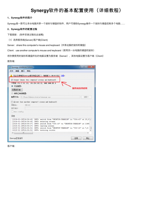
Synergy软件的基本配置使⽤(详细教程)1、Synergy软件的简介Synergy是⼀款可让多台电脑共享⼀个⿏标与键盘的软件,⽤户可借助Synergy操作⼀个⿏标与键盘控制多个电脑……2、Synergy软件的配置过程下载链接: (软件安装过程在此省略)(1)选择服务端(Server)/客户端(Client)Server:share this computer's mouse and keyboard(共享此脑的⿏标和键盘)Client:use another computer's mouse and keyboard(使⽤另⼀台电脑的键盘和⿏标)将你要使⽤的⿏标和键盘所在的电脑设置为服务端(Server),其他电脑设置为客户端(Client)服务端:客户端:(2)配置服务端点击【设置服务端选项】创建⼀台客户端电脑:创建后:将创建后的电脑进⾏命名,切记必需要命名为客户端电脑对应的屏幕名称查看客户端屏幕名称:双击”未命名“的电脑图标,进⾏屏幕设置,只需要修改屏幕名称:正确命名后,点击【OK】(其它保持默认):PS:布局指明客户机端和服务机端的实际相对位置(当前设置为客户机端在左,服务机端在右)。
当然,你也可以把客户机端放在其它位置,但要相对于服务机端放置。
点击【开始】,运⾏Synergy服务端(3)配置客户端在客户端输⼊服务端的IP地址,必需正确输⼊才能与接服务端连接最后启动客户端,客户端正确显⽰“Synergy正在运⾏”:⾄此,便可实现了多台电脑共享⼀个⿏标与键盘。
注意:如未成功,查看⽇志消息,出现了“Cursor is locked to screen, check Scroll Lock key”的⽇志提⽰:原因:开启了滚动锁定(Scroll Lock)功能解决⽅式:关闭键盘滚动锁定功能。
Synergy 2000 中文产品介绍

应用效果具有典型的代表性
投资回报比预期更快速,更加令人兴奋!
交互式的全面监控
实时监控使得管理者不需要到现 场便知晓多个设备或过程状态。 多个控制特性的数据、图表和数 据表同时在同一屏幕显示。“信号 灯”作为过程状态标志,数据点 状态预示了每个控制特性、零件 或过程的变化,管理者一眼就能 确定过程是否受控。在软件窗口 最小化时,当过程失控和超出规 范状态的情况下,系统自动弹出 警告窗口提醒管理者。
统将弹出警告窗口提醒操作者, 同时发送email给相关的人员。 可以直接复制和粘贴 Synergy 2000图表 和数据到其他 Windows应用程序, 如Word或Excel等。 同时在软件中可以直接显示 零件设置图或操作指南 等文件,以减少纸面 文件的传递与查看。 客户化的定义屏幕显示, 可以让用户重点关注某 一重要的方面。整个程序完全基 于简单易用和最大满足用户的应 用要求而设计。
操作和图表应用
无须设定基本图表和电子表, Synergy 2000给出了多种选择: 正态与非正态数据分析、6δ过程 能力与损失函数分析、Short Run
甚至包括最基层的操作工人!
和Gage R&R图等等,多种图表 同时显示,并行比较。检查某点 或缩放数据的详细情况,在一张 图表上观察所有历史数据,涵盖 多种图表,真正找到引起过程变 化的事件。
采集数据,生成正确的控制图表,查询分 析和形成报告等只需要点击一下鼠标就可 以轻易完成。Synergy2000提供非常快捷 的性能,因为它完全基于制造业应用而设 计,让您能瞬间反馈并识别质量目标内容 或一些无用的工作。 非常简单的应用与维护,质量部门的人员 就可以非常容易地进行维护与应用支持, 而且对于SPC文件的创建、过程参数改 变、设计报告或提供系统日常的运行管理 都不需要专门的程序人员或数据库专家。
- 1、下载文档前请自行甄别文档内容的完整性,平台不提供额外的编辑、内容补充、找答案等附加服务。
- 2、"仅部分预览"的文档,不可在线预览部分如存在完整性等问题,可反馈申请退款(可完整预览的文档不适用该条件!)。
- 3、如文档侵犯您的权益,请联系客服反馈,我们会尽快为您处理(人工客服工作时间:9:00-18:30)。
实现以下两台计算机合用一套键鼠,“系统属性”对话框,可右击“我的电脑”“属性”调出。
计算机A 计算机B
系统:windows xp 系统:windows xp
完整的计算机名称:xpA 完整的计算机名称:xpB
局域网IP地址:192.168.1.111 局域网IP地址:192.168.1.112
选取计算机A做为服务器端,使A上插的键鼠可以控制计算机B
A端设置:
打开计算机A上的Synergy,点击Configure
在跳出来的“Screens&Links”中选中“+”,添加入计算机A与计算机B的完整的计算机名称,xpA与xpB。
在“Links:”栏下填写好下拉框后,按“+”号键,来设置两个屏幕的位置,本文设置如此处文字上方与文字下方的两幅“Screens&Links”图所示。
设置的含义如下:
0 to 100% of the right of xpA goes to 0 to 100% of xpB鼠标从xpA的右边移出到达xpB 0 to 100% of the left of xpB goes to 0 to 100% of xpA鼠标从xpB的左边移出到达xpA
确认后退回主界面,选中“Advanced…”,在跳出的“Adwanced Options”对话框中,填写Screen Name为xpA,Interface为xpA的IP地址:192.168.111。
确认后返回主界面,A端设置完成,按“Test”或“Start”开始连接。
B端设置:
进入主界面,选择“Use another computer’s shared keyboard and mouse(client)”,在“Other Computer’s Host Name”中填入服务器A端的IP地址:192.168.1.111。
设置完成,选择“Test”或“Start”即可使用。
设置结束,尽情享受两台机子任意切换的欢乐吧!!!!。
