曼瑞德混水中心用户手册控制器调整说明
pH 和 ORP 控制器 变送器 说明书

1.3 安全说明 pH/ORP 变送器必须由熟悉这类工作有资格的工作人员来安装和操作。
有问题的变送器不能被安装也不能投入使用。 pH/ORP 变送器必须工作在规定的工作条件下(参见第 8 项)。 pH/ORP 变送器不能由客户自行打开修理。 改装过的 pH/ORP 变送器是不能使用的。生产商/供应商不承担任何因未经许可私 自改动仪表而造成损坏的责任。由客户完全承担由此带来的风险。
8
2 产品描述
2.1 仪表描述
EUTECH 仪器有限公司的 pH/ORP 变送器是用来测量 pH 或 ORP 和温度值。pH 或 ORP 测量 值可以用比例或极限点的方式来控制。
该款变送器有两个版本,一种是表盘安装方式另一种是壁挂式安装方式。变送器可被用 于水处理中作为监测仪、电解净水、化工流程、食品流程、净水或污水控制和中和过程。
43
10.3 返修
43
10.4 产品返修指南
43
11 附件
44
11.1 附件 1 – Pt 100 / Pt 1000 选择
44
11.2 附件 2 – pH 缓冲溶液对应温度值
45
11.3 附录 3 – 迟滞宽度
46
11.4 附录 4 – 控制动作
47
11.5 附录 5 – 显示菜单中的缩写词
49
6
感器故障。
• 清洗继电器。 • 锁定功能可固定住 0/4—20mA 输出电流并且可以释放继电器。 • LED 指示可以从远处清楚地知道仪表的控制激活状态。 • 抗电磁干扰。 • 防紫外线、背光液晶显示。
9
2.2 测量和控制系统
典型的测量系统有以下部分组成: • pH/ORP 在线变送器。 • pH/ORP 复合电极合并或独立的温度传感器 Pt100/Pt1000。 • 合适的 pH/ORP 测量电缆线。 • 浸入式、流通式或流程配件有或没有接地电极。 • 终端的控制部件,如泵或阀。 • 记录仪
水控系统使用说明书

目录
前言................................................................................................................................. 1 一、系统介绍................................................................................................................... 1
为了节约水资源,我公司生产的红外水控,可以很好的为公司,工 厂,学校等企业各类 人群提供一个节水设备,从而增强人们的节水意识,又能节约水资源成本。
我公司的推出的智能红外水控具有计费准确、控制灵活、使用方便的特点。从而达到“按
需用水、合理消费、智能管理”。
一、系统介绍
1 、 系统组成
·安装有水控管理软件的 PC ·水控机 ·水控电源 ·发卡器 ·电磁阀 ·流量表(可选) ·485 转换器及连接线(联机下使用) ·IC 卡
智能水控器应用于已采用一卡通系统的学校、企事业单位,安装在有水龙头流水的场所。 当用户将卡放置到水控器卡感应区,读卡芯片就会获取卡上的信息,并将相关数据发送回单 片机,由单片机控制数码管显示用户余额,再对余额进行判断看是否大于单位扣费金额,若 余额足够则控制电磁阀打开,出水,流量传感器将流经的水转换成电脉冲信号输入单片机, 之后单片机通过预设费率将用水量转换成金额并进行扣费,数码管动态实时显示用户当前金 额。当卡拿走后,单片机自动关闭电磁阀,停止供水,水控器随即进入待机状态,仅显示当 前机号。卡消费信息可通过上位机软件发送指令来查询
LMR PLUS 电动消防水泵控制器 FD40 说明书

Membrane KeypadDoor MountThe membrane keypad is accessible from thefront door of the controller.NEMA RatingThe standard membrane keypad is rated forNEMA 2, 3R, 4, 4X and 12.Alarm & Status LED’sA total of 20, ( 10 Status - 10 Alarm ) LED’sprovide indication on the membrane keypad. Product DescriptionThe FD40 LMR Plus Controllers are a fullservice, part winding reduced voltage controller.A part winding fire pump controller reduces thestarting current by up to 40% while maintainingup to 50% motor starting torque. The FD40 isthe most economical method of reducedvoltage starting, however, requires a specialmotor wound for part winding starting. TheFD40 can be programmed for either fullyautomatic or semi-automatic operations.The use of an embedded web page forretrieving diagnostics and history reports, alongwith USB and Ethernet communication ports fordownloading data, make the LMR Plus Series ofcontrollers easy to troubleshoot and maintain.As well, critical information can be easilyaccessed and used for report generation andanalysis, which aids in providing effective,reliable fire protection.Alarm LED’sStatus LED’sPhase ReversalPhase FailureFail To StartUndervoltageOvervoltageLow Room TemperatureLocked Rotor TripLow Suction PressureSource 2 DisconnectedProgrammable LED # 2Power OnPump RunningLocal StartRemote StartDeluge ValveEmergency StartInterlock OnLow PressureAuto Shutdown EnabledProgrammable LED # 1Power I/O BoardTransformersIncoming line voltage is run directly to the I/Oboard from the incoming lines. The I/O boardwill accept voltage inputs between 100 and600V.Silence ButtonA silence pushbutton on the membrane can beused to silence the buzzer. When an alarmcondition exists, the alarm buzzer will sound. Ifthe Silence Alarm button is pressed, the alarmbuzzer will turn off. If a subsequent alarmcondition occurs after the silence button ispressed, the buzzer will re-sound. Pressing theSilence Alarm button again, will silence thebuzzer.Motor Test ButtonThe motor test button on the membrane can beused to simulate an automatic start.Automatic Shutdown EnabledWhen the Automatic Shutdown function isenabled, a Green LED will indicate on thecontroller membrane.USB External DriveGeneralWhen using an external USB Drive, the driveshould conform to the following specifications:Min: 128mbMax: 2 Gig FAT16 protocolUSB 1.0 or 2.0Standards & CertificationNEMA 2 EnclosuresAll LMR controllers come standard with NEMA 2enclosures unless otherwise ordered. Availableoptions include: NEMA 3R, 4, 4X, 12.Emergency Start OperatorA mechanically operatedemergency start handleactivates the motorcontactor independent ofany electrical controlcircuits or pressureswitch input.Product FeaturesLogic Controller BoardCommunicationThe controller can be ordered with the option todisplay and output current values and status, oncommand, from various software protocolsthrough the appropriate port(s).Embedded Web PageThe web page is a multifunction tool that allowsthe user to view the controller’s current status,data values, programmed set points and history.It is accessed using the optional ethernet port.Ethernet PortAn optional Ethernet port can be used for directconnection to a computer for data transfer.RS485 Serial PortAn optional RS485 serial port can be providedfor communication to various external softwareprograms.USB Port / USB DriveThe logic controller board is equipped with aUSB port that can be used to transfer data toand from a portable USB Drive device (memorystick).BuzzerA buzzer is mounted on the logic board whichwill operate if Fail to Start, HardwareMalfunction or any Common Alarm conditionexists.Customer Connection TerminalsConnection terminals for external customerconnections, are located at the top of the PowerI/O board.Output RelaysFive, 8 Amp, 2 Form - C (DPDT) output relaysare provided standard on each power I/O board.They are designated for: Common Alarm,Phase Failure, Phase Reversal, Pump Run andFuture #1. Each socket has an LED mounted onthe I/O board which indicates each relay’s coilstatus.Optional Output Relay BoardsThere is provision to add up to eight additionalrelay outputs, via optional relay output boards.Each board contains a maximum of 2 additionalrelays. The Power I/O Board will accept amaximum of 4 optional boards which mount in asnap-on configuration.Each board provides an area for the user tolabel the terminal number and relay name.Drain Valve SolenoidAll LMR Plus electric controllers are equippedwith a drain valve solenoid used for weekly testpurposes.N. Y. C.APPROVEDThe LMR Plus Electric Fire Pump Controllersmeet or exceed the requirements ofUnderwriters Laboratories, UnderwritersLaboratories Canada, Factory Mutual, theCanadian Standards Association, New York Citybuilding code, CE mark and U.B.C / C.B.C.Seismic requirements, and are built to NFPA 20standards.Product FeaturesMain DisplayGeneralThe main display will show the current system pressure, time and date, voltage and amps reading for all three phases, the system frequency and any custom messages, alarmsor timers.Programmed Set-PointThe set-point display will show programmed pressure start point, pressure stop point and weekly test timer setting.StatisticsThe statistics display will allow the user to scroll through all of the measured statistics stored in memory. Refer to LMR Plus operation manual IM05805020K for specific details. DiagnosticsThe diagnostics display allows the user to scroll through various diagnostic points to assist with troubleshooting the system. Message HistoryThe user will be able to scroll through all of the messages stored in the memory of the controller with the most recent message being displayed first.PRINT MenuDescriptionAll fault and alarm information is sent to the USB and optional printer on demand, as well as the status of each output. The LMR Plus will store up to 10K events which are time and date stamped. All information can also be retrieved and displayed on the LCD display.Saving to USB DriveThe controller will save four separate text files, one CSV file and the embedded webpage to the USB external drive. The files, at maximum size, can be saved multiple times on one 128MB USB drive.Files to be saved are: Status Report, Diagnostics Report, Statistics Report, Configuration File and Last 10K Messages. Print MenuThe optional printer menu is accessed in order to select the desired print function.Functions include: Print Messages, Last XX Messages, Date & Time, Status Report, Diagnostics Report and Statistics Report. Custom MessagesWhen this item is selected, custom messages can be cleared from memory or downloaded from the USB external drive. Embedded Web PageGeneralThe embedded web page is a multifunction tool that will allow the user to view the current status of the controller as well as display all current readings, set points,and history. An externalcomputer can beconnected via theoptional Ethernetport to access thepage. Whenconnected, thecontroller setpoints can beprogrammedvia the webpage.Multiple PagesThere are 5 viewable pages that show the Main Display, Statistics, Diagnostics, History and Programmed Set Points.Pressure PointsThe pressure reports recorded in memory can be graphed and/or sorted based on date and time.Programmed Set PointsAll of the programmed set points and their current status can be viewed via the webpage. Custom MessagesTrigger PointsThe message can be programmed to appear at specific trigger points such as specific date and time, specific number of operations, specific number of hours run or at any individual alarm point.All of the trigger points can be selected asAnd/Or values.Users can create custom messages on a computer and upload to the controller using a USB Drive (memory stick). Up to 10 custom messages of up to 100 characters each, will continuously scroll across the fourth line of the LCD display once triggered.Firmware UpdateFirmware revisions are updated from an external USB drive. All previously programmed settings will remain intact when updating is completed. Should there be an update failure, the controller will automatically revert back tothe previous version of firmware. Programming MenuGeneralThe LMR Plus programming menu is divided into 8 different sub-menus. Each sub-menu contains information relative to it’s particular function. Following is a brief description of each nguageThe language sub-menu allows the user to select English, French, Spanish or Other languages to be viewed on the LCD Display. Several other languages can be uploaded into the controller. Contact the factory for details.RegionalRegional settings include the ability to program the date by adjusting the Month, Day, Year and Day of Week. As well, the Current Time can be adjusted on the 24 hour clock.PressureA variety of pressure settings can be programmed in the pressure sub-menu. These settings include disabling the pressure transmitter; setting of the start point, stop point, low pressure alarm, high pressure alarm, stop mode, proof pressure switch (for foam units), low suction shutdown (low foam shutdown), pressure deviation and hourly pressure recording. Refer to the LMR Plus operation manual IM05805020K for details.TimersTimers in the LMR Plus that can be programmed include: Run Period Timer (RPT), RPT Start Mode, Acceleration Timer (AT), Weekly Test Timer, Fail to Start Timer (FST) and Sequential Start Timer (SST). Refer to the LMR Plus operation manual IM05805020K for details. Alarm Set PointsThere are five settable alarm points that can be programmed by the user. They include: Phase Rotation, Over Voltage (OV), Under Voltage (UV), Over Frequency (OF) and Under Frequency (UF). Refer to the LMR Plus operation manual IM05805020K for details.Custom Inputs / OutputsThere is provision on the Power I/O Board to accept up to 9 additional inputs and 9 additional outputs. Each of the inputs can be labeled using m conditions.All optional inputs, outputs and LED’s can be linked, as required.Inputs can be programmed to energize the common alarm output, link to relays and optional LED’s and latch until reset by the user.Outputs can be programmed for fail safe and latch until reset by the user.Optional inputs and outputs can be programmed with time delay functions.one of 11 pre-set input descriptions or assigned a custom description that is programmed by the user. The optional outputs can be programmed to indicate up to 25 output conditions. As well, two optional alarm LED’s can be programmed for up to 12 alarSystem Configuration MenuThe system configuration menu section is password protected and contains settings such as system voltage, frequency, CT ratio etc. Refer to Technical Bulletin PU05805035K/Dfor details.Main Menu PasswordA password can be programmed by the user to protect access to the Main Menu. Refer to the LMR Plus Operation Manual IM05805020K for details.。
瑞乐科 'RD-1' 2-路正常开路水力控制器操作手册说明书

‘RD-1’ DUMP VALVE MODEL 8001 OPERATION MANUALMANUAL # OMP - 8001 - 06 - 11 (SEE SPEC. SHEET 8001)I. PRINCIPLE OF OPERATIONThe Ruelco ‘RD-1’ is a 2-way, Normally Open Hydraulic Controller that acts as a snap acting vent valve on loss of pilot pressure. This configuration of the Ruelco RD-1 permits control of hydraulic pressure up to 10,000 psi. A pilot supply of 100 psi. is necessary to control 10,000 psi. of hydraulic pressure.A high ratio of hydraulic pressure to pilot control pressure ensures safe operation. A soft seal design ensures zero leakage in the hydraulic section. Ruggedly constructed stainless steel process wetted parts provide years of reliable service and the compact and simple design makes field maintenance easy.II. INSTALLATIONThe‘RD-1’ can be mounted either vertically, horizontally, or supported by piping from any of its ports. If it is supported by piping, care should be taken that the strength of the pipe fittings used is adequate to prevent the fitting from breaking off in the valve body should the valve be inadvertently struck. Proper pipe thread sealant should be used on any pipe fittings threaded into the valve ports. If stainless steel fittings are used, a sealant that will prevent galling is required. III. DISASSEMBLY (REFER TO SPEC. SHEET 8001)All Control and Pilot Pressure should be vented before Disassembly •Suitable adjustable wrench forremoving the Hex Plug•Pick to remove o-ringsNote: All Item Numbers Refer to the 8001 Model unless otherwise Noted. Spool Seals1) To replace O-rings on the spoolassembly (Item 1), the cap must beremoved.2) Unthread the Cap (Item 1).3) Pull the Spool and Piston (Item 9 and4) out of the Cap. Be careful not tolose the spring.4) The seals on the Piston and Spoolseals may now be replaced as perinstructions given in the repair section of this manual.Body Seals1)Unthread the Hex Plug (Item 13)2)Using the pick, insert the pick intothe Body, being careful not todamage the inside edges and removethe Polypak Seal (Item 10) out of thebody.3)Now, also using the pick, remove theHex Plug seals (Items 11 and 12).IV. REPAIR AND ASSEMBLY1) Remove the seals from the Spoolassembly, Body, and Hex Plug2) Using an appropriate safety solvent,clean all parts.3) Inspect the shaft assembly for anymajor damage such as burrs, knicks.Also, inspect it for straightness.Replace the shaft assembly ifdamaged.4) Examine the valve body for anydamage such as burrs, nicks, etc.Replace if damaged.5) Examine the Polpak Seal (Item 10)and replace if damaged. The Centerseal can be removed with the pick.Insert the new seal into the cavity.Most of the seal should fall in easily.The Hex plug will finish completelyseating the seal.6) Replacement seals for a Ruelcoproduct repair kit are required forproper valve performance. It isrecommended that all seals belubricated before and after installation with a high qualitysilicon based grease included in therepair kit.7) Lubricate the inside of the Body(Item 8). Replace the Polypak Seal(Item 10). 8) Install the Hex Plug into the bodymaking sure that the Polypak Seal isalso orientated upward.9) Replace the Spool and Piston o-rings.10) Finally, install the spring into theBody and place the spool and pistoninto the body. Screw the Cap back into place.VI. RECOMMENDED MAINTENANCEPROCEDURE INTERVALOperate Manually. Every 30 days. Disassemble, inspect and lubricate. Yearly or as required.Replace all seals. Every two (2) years or as required.。
恒温混水阀的使用及调试注意事项
恒温混水阀的使用及调试注意事项内容来源自网络1、调试温度时应把出水流量开到最大。
2、调节钮正旋方向是降温、逆旋方向是升温,初次调节请注意从低温方向往高温方向调节,以防烫伤。
3、调节钮低温方向听尽头是关闭热水,高温方向的尽头是关闭冷水,如果1、调试温度时应把出水流量开到最大。
2、调节钮正旋方向是降温、逆旋方向是升温,初次调节请注意从低温方向往高温方向调节,以防烫伤。
3、调节钮低温方向听尽头是关闭热水,高温方向的尽头是关闭冷水,如果热水温度不高,可以关闭冷水只用热水洗浴,但使用过后应注意高回低温区域,以免下次使用时发生烫伤。
4、如果冷、热水进水压力不一致,且没有安装单向止流阀,请注意每次使用后,将调温钮调到低温方向尽头,即关闭热水状态,最大程度防止冷热水互串。
采购前阀门选型的步骤和依据:在流体管道系统中,阀门是控制元件,其主要作用是隔离设备和管道系统、调节流量、防止回流、调节和排泄压力。
由于管道系统选择最适合的阀门显得非常重要,所以,了解阀门的特性及选择阀门的步骤和依据也变得至关重要起来。
阀门行业到目前为止,已能生产种类齐全的闸阀、截止阀、节流阀、旋塞阀、球阀、电动阀、隔膜阀、止回阀、安全阀、减压阀、蒸汽疏水阀和紧急切断阀等12大类、3000多个型号、4000多个规格的阀门产品;最高工作压力为600MPa,最大公称通径达5350mm,最高工作温度为1200℃,最低工作温度为-196℃,适用介质为水、蒸汽、油品、天然气、强腐蚀性介质(如浓硝酸、中浓度硫酸等)、易燃介质(如笨、乙烯等)、有毒介质(如硫化氢)、易爆介质及带放射性介质(金属钠、-回路纯水等)。
阀门承压件材质铸铜、铸铁、球墨铸铁、高硅铸铁、铸钢、锻钢、高、低合金钢、不锈耐酸钢、哈氏合金、因科镍尔、蒙乃尔合金、双相不锈钢、钛合金等。
并且能够生产各种电动、气动、液动阀门驱动装置。
面对如此众多的阀门品种和如此复杂的各种工况,要选择管道系统最适合安装的阀门产品,我以为,首先应了解阀门的特性;其次应掌握选择阀门的步骤和依据;再者应遵循选择阀门的原则。
全自动软水器使用说明书

目录一、产品概述 2二、工作流程图 3三、设备的系统说明 5四、设备的安装和运行 6五、设备安装示意图7六、流量型控制器调试步骤8七、时间型控制器调试步骤9八、故障排除11产品概述FLECK全自动控制器以闻名于世的FLECK公司软化水技术为基础,它是将软水器的运行及再生的每一个步骤实现全自动控制,并采用时间、流量或感应器等方式来启动再生。
调整FLECK系列全自动软水器采用时间同步电机控制全部的工作程序,在7天或12天围根据需要设定还原周期,二十四小时任意选择还原时间,并可以对还原过程进行调整。
富来流量型全自动软水器采用流量控制全部工作程序,设备可连续(或间断)供水。
再生—由流量控制器自动启动再生装置,可根据需要自行设定再生程序。
由于FLECK系列全自动软水设备控制系统技术成熟、操作简便、采用了无铅黄铜阀体完全符合食品卫生要求,配以聚四氟乙烯(Teflon)涂层活塞减小了阻力,延长了使用寿命,运行可靠。
FLECK系列全自动阀门应用于工业锅炉、热交换器、大型中央空调、宾馆饭店、食品工业、洗衣印染、医疗卫生等行业,该产品具有自动化程度高、交换容量大、结构紧凑、能耗低、省人工、无需日常保养等特点。
进口压力:0.2Mpa—0.6Mpa工作温度:2℃--50℃出水硬度:≤0.03 mmoI/L使用电源:220V/50Hz AC布置形式:单罐或多罐并联再生方式:顺流再生或逆流再生操作程序:自动程序控制使用树脂:001×7强酸性阳离子交换树脂我公司将为用户提供完善的技术服务。
MODEL2510、2750、2850、3150、2900、3900工作流程图1、工作状态2、反洗状态3、再生状态4、慢速清洗状态硬水经过控制阀进入树脂罐,经树脂层处理的水通过底步的布水器,进入沿着中心升降管向上,再通过控制阀流出。
硬水进入控制阀后经过:控制阀中心升降管向下通过底部的布水器经过树脂层向上最后通过控制阀排水口排出硬水进入控制阀后,向上进入注水器,然后通过射流过程将盐罐中的还原剂吸入,带还原剂的水流向下经过树脂层进入布水器和升降管,再通过控制阀排水口排出。
C-90混水器使用说明书
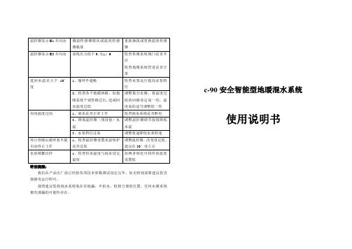
特别提醒:我们在产品出厂前已经将各项技术参数调试设定完毕,如无特别需要建议您直接插电运行即可。
强烈建议您将混水系统装在有地漏,不怕水、检修方便的位置,任何水暖系统都有泄漏的可能性存在。
c-90安全智能型地暖混水系统使用说明书一、技术参数:1、额定电压:AC220V 50HZ;2、限温式断水保护温度:5-95℃(出厂设置40℃)3、混水控温:±1℃4、控温范围:5-95℃(出厂设置40℃)5、系统循环泵扬程:6m(最高扬程)6、最大功率:98W(水泵运行时)7、管路公称压力:PN10 8、供水温度不高于95℃9、面积200㎡以下 10系统压力低于0.5bar或高于6bar系统断电,进水阀自动关闭11、低温启动模式:水温高于20°但低于设定值5°阀门泵开,水泵呈间歇式运行(可以设置其它温度)二、混水系统安装及保养注意事项:1、混水系统各个部件结构及安装尺寸请对照所选购产品的示意图进行安装连接,进回水装反系统无法正常工作。
2、为了便于以后的维修和系统的正常运转,强烈建议用户在集中供热进水口加装过滤装置。
3、本系统安装前,应检查管路系统是否连接可靠,并确保管道中的杂质、焊渣、污垢已经清除干净:电源频率为50HZ,电压为单项220V,电压波动值应在-10%~+6%;4、系统应安装在干燥通风处,以防受潮短路或被水喷溅,且安装便于以后维修和更换;5、系统为配套供热系统工作时,切勿用手触摸电泵及其管路,以免烫伤;6、电源插头应严格接地,将插头接地脚与电源插座接地孔进行可靠连接,不得擅自改变混水接地插头;7、混水系统工作时,应在使用场地建立醒目安全警示标志,谨防发生意外事故;8、如系统出现渗漏现象维修时或有触及电泵、控制器的动作时,必须先切断电源,以防意外事故发生;四、温馨提示:传感器出现故障,温控器关闭输出,并显示相关错误代码。
E1:室温传感器短路报警;E2:室温传感器断路报警;五、安装:1.固定好支架,按照要求接上分水器。
混水系统及详细说明书
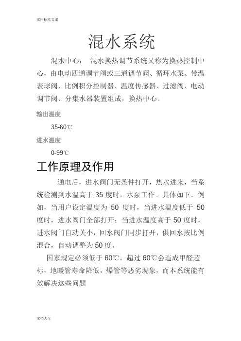
混水系统混水中心:混水换热调节系统又称为换热控制中心,由电动四通调节阀或三通调节阀、循环水泵、带温表球阀、比例积分控制器、温度传感器、过滤阀、电动调节阀、分集水器装置组成,换热中心。
输出温度35-60℃进水温度0-99℃工作原理及作用通电后,进水阀门无条件打开,热水进来,当系统检测到水温高于35度时,水泵工作。
具体如下。
例如,当用户设定温度为50度时,当进水温度低于50度时,进水阀门全部打开;当进水温度高于50度时,进水阀门自动关小,回水阀门同步打开,供回水按比例混合,自动调整为50度。
国家规定必须低于60℃,超过60℃会造成甲醛超标,地暖管寿命降低,爆管等恶劣现象,而本系统能有效解决这些问题主要应用范围及特点集中供暖+地暖锅炉+地暖散热器,地暖混装系统混水系统采用国际领先的屏蔽水泵,耗电低(最低46瓦,最高100瓦)噪音低≤45db,寿命长,可连续5000h连续工作(有水)技术参数使用面积:160㎡(常规)温控精度:±2℃流速:0.25-0.4m/s扬程:6m一次供水额定流量:1200L/h二次供水额定流量:300L/h分水器中心间距:210mm最大工作压力:0.8mpa噪音≤45db防护等级:IP44功率:46-100瓦材质:黄铜进水方向:左进水或下进水安装注意事项1.安装前,应彻底检查管路系统,是否连接可靠,并确保管道中杂质焊渣污垢已经清除干净,尤其是北方使用PPR管道焊接时,确保焊接后流量不能太小2.供回水处均需加装阀门,便于以后维护,保养,供水处必须加装过滤器,以保护水泵,条件许可下尽量采用水平进水,其次是下进水。
3供回水连接正确,不得接反。
4本系统一般应安装在干燥通风处,以防受潮短路或被水喷溅,附近最好有地漏。
5安装:配有专用支架(上下间距为220mm)1用户及调试人员在使用及调试中除温控器及塑料部位外,应严格遵守用电常识,一般不得触摸其它金属部位,以防烫伤及其它意外。
2.当用户需要调整温度时,只需按上下键即可3.电动执行器的旋钮水平时为全关,垂直(与地面)为全开4.手动操作:不通电时,按下电动执行器进行旋钮,呈垂直(与地面)状态,相当于没装该系统,这时热水应该能自然循环(这是一切工作的前提),如果不能自然循环,要检查阀门是否全部打开及是否有压差。
Myron L 6P中文操作说明书

一序言感谢您选用麦隆公司最新一代先进的便携式UltrameterTM6P型多参数水质检测仪。
这款仪器将使您的操作变得非常简单方便。
为了方便起见,在仪器的底部有一简单的介绍及附有一张袖珍卡片,上有仪器的简单操作说明。
注意:电导,电阻和TDS需要校正到250C时的值。
在液晶显示屏的左方,显示KCl,NaCl,442和USER四种类型,他们是用于电导和TDS转换时进行温度校正所选择的对应溶液,溶液类型不同,则相应的温度校正系数不同,以及电导和TDS的转换系数也不同。
溶液的温度高低导致溶液的电导值不一,相应的TDS值也不一。
一般地,校正溶液的电导时选用KCl,电阻选用NaCl,TDS选用442(自然水)这取决于目前工业发展的水平。
以下是这款原装进口仪器的操作说明。
二操作规范A 操作使用简单1)只需将试样注入一个或多个电极池,就可以读取一个或多个参数值,2)用待测液润洗电导池或pH/ORP电极池三次并重新加液,3)按取要测试的参数键就可以读取参数值,如无按键,则仪器会在15秒后自动关闭,4)读取数值后,要存储该数值,按MS键就可以保存,就这么简单。
B 按键功能1)虽然仪器带有很多的按键,但无论测那一个参数,都只要按取一个键就可以迅速准确的进行测量,2)每个键都有固定程序设计,按一次键,就执行一次程序,3)仪器没有“off”键,在最后一次按键后15秒,仪器自动关闭(在cal模式下,60秒自动关闭),4)一般情况不需要持续按住一个键,按一下就可以。
C 按键的操作1)一般测试按键区上面五个测试键任意一个都可以开启仪器并选择相应的测试类型进入测试模式.选择的测试类型显示在屏幕的底部,参数的单位显示在右面,如在校准或取消更改设置的模式下,按测试键,同样可以进行测试。
2)电导,RES和TDS这三个键可测试在电导池中的溶液的参数值。
注:i在加入待测液时,要避免有气泡混入电导池里;ii如发现测试时,溶液的选择类型(KCl,NaCl,442和USER)与所测参数不符,则查看“溶液类型选择”一项选择相应溶液类型。
pH ORP控制器 使用说明书
杭州美控自动化技术有限公司更多资讯请扫二维码服务电话:400-152-1718杭州美控自动化技术有限公司 U-PH3-MKCN1第1版pH/ORP控制器使用说明书前言 前言感谢您购买本公司的pH/ORP控制器。
本手册简明地介绍了pH/ORP 控制器的安装、接线及操作说明。
为了确保正确使用本产品,请在使用之前先阅读本手册。
注意●因本产品的性能和功能会不断改进,本手册内容如有更改,恕不另行通知。
●本公司力求本手册的正确、全面。
如有错误、遗漏,请和本公司联系。
版本U-PH3-MKCN1 第一版2018年8月安全注意事项安全注意事项为了安全使用本产品,操作时请务必遵守此处描述的安全注意事项。
关于本手册●请将本手册交于操作者阅读。
●在操作之前,请熟读本手册,并对产品有深入了解。
●本手册只对产品的功能进行阐述,本公司不保证该产品将适合于用户的某一特殊用途。
本产品保护,安全及改造相关注意事项●为了确保安全使用本产品以及由其控制的系统,操作时请务必遵守本手册中所述说明和注意事项。
如果违反操作规程,则有可能会损坏本产品所提供的保护功能。
对由以上情况产生的质量、性能、功能和产品的安全问题,本公司不承担任何责任。
●为本产品及其控制系统安装防雷装置,或为本产品及其控制系统设计安装单独的安全保护电路时,需要借助其他的设备来实现。
●如需更换产品的零部件,请使用本公司指定的型号规格。
●本产品不适用于直接关系到人身安全的系统。
如核动力设备、使用放射能的设备、铁路系统、航空机器、船舶设备、航空设备和医疗器械等。
如有应用,用户有责任使用额外的设备或系统确保人身安全。
●请勿改造本产品。
安全注意事项 在本手册中使用以下几种安全标志:危险标志,若不采取适当的预防措施,将导致严重的人身伤害、产品损坏或重大财产损失等事故。
警示标志,提醒您对产品有关的重要信息或本手册的特别部分格外注意。
●在接通本产品的电源之前,请先确认产品的电源电压是否与供给电源电压一致。
德国瑞德GW系列用户使用说明书

反渗透混床系统操作手册

*操作本系统之前必须仔细阅读本操作手册*如果有任何疑问请咨询www。
wxryf。
com一、概述1.本系统操作手册专为富士通(苏州)有限公司纯水系统而制定.2.城市自来水通过本系统装置处理,将水中的颗粒物质、阴阳离子等去除,使出水水质达到规定要求的电阻率2MΩ·cm(RM—220电阻率仪)以上、PH6。
0~7。
0。
3.根据出水要求的技术指标,本系统工艺流程为:说明:1。
预处理由原水泵、砂过滤器、活性碳滤器、5μ滤器、投药系统等组成。
其目的是全部或部分去除原水中的机械杂质、悬浮物、微生物、胶体、溶解性气体(主要针对水中的余氯而言),以及部分无机、有机杂质等,以达到后级工序的进水要求.2.预脱盐系统由高压泵、两套一级反渗透机组、清洗系统等组成.初步脱除水中的溶解性固体,同时也能去除前道工序没有去除的有机物、颗粒及大部分细菌.3.深度脱盐由混合床组成。
进一步去除水中的溶解性离子、可溶性硅等.4.后级处理由0.22μ滤器、纯水箱、纯水泵等组成。
进一步去除水中的细小颗粒,达到最终电阻率≥2MΩ·cm(25℃)出水要求的指标。
5.详图见工艺流程图。
二、主体设备操作1.在加药箱中按1%比例配制ST絮凝剂,搅拌均匀后开启加药泵.加药浓度根据SDI仪测定值每星期修正一次。
2.打开输送泵,将原水送至沙过滤器内。
3。
砂过滤器(见图):3—1作业前点检a 检查容器的各个部件是否正常及其它设备是否接通。
b 各阀门位置确认.3—2操作方法启动原水泵,开启阀F2、F5,然后开启F1并用阀F2(或F1)设定流量至8.0m3/h。
冲洗几分钟后开启阀F6、关闭阀F5进入工作状态。
3-3定期点检a 反洗周期为1次/日.b 精制石英砂更换周期为1次/2年。
c 床层压力为0.05MPa以下。
d 出水流量8~10 m3/h.e SDI值测试周期1次/每星期.f ST絮凝剂加药周期为1次/日.3-4异常时的处置当床层压降(进出水压力差)至0.08~0.1MPa或出水水质恶化(SDI值超标)时,则停止工作周期,进入反洗周期.反洗的方法如下:a 气冲(过滤器内精制石英砂严重污染时使用):打开排气阀F7,打开淋洗出口阀F5,降低容器中水位至砂层平,关闭淋洗出口阀F5,缓慢地打开空气入口阀F8,用F8设定空气冲刷流量,观察气冲情况,看到石英砂剧烈翻动为准.气冲完毕,关闭空气入口阀F8、排气阀F7。
menred 自平衡新风机 说明书

敬告:中央新系统产品的外观、构造、技术已获得中华人民共和国识产权保护,仿造必 属于MENRED 中国独资公司。
本产品已列入全国质量监督防伪系统,为重点保护品牌,您可以通过拨打防伪系统电话 输入密码查询真伪,或登陆 官方网站输入密码进行查询!风专利知究!知识产权4007072315中央新风系统用户手册源于德国 共享科技MENRED GmbH自平衡新风机致尊敬的用户曼瑞德中央新风系统menred central ventilator system首先,非常感谢您选择了本公司中央新风系统的产品,使我们有机会为你提供服务,并用我们的产品为您营造一个更舒适,更节能,更健康的生活环境。
现在都市由于人员高度集中、拥挤、抽烟所产生的灰尘、烟雾、加上人体呼出的CO ,以及室内装潢所散发出的种种不良物质,使得室内空气污浊、2质量低劣。
每个人一天平均呼吸25920次。
我们一天需要1.5公斤的食物和2公斤的水,但却需要12公斤的空气。
所以人们需要一种有效提高生活质量和居住环境的方法,而拥有一套高效合理的中央新风系统是确保室内空气质量的关键因素。
1、解决家装污染,把家装后室内含有甲醛、苯、氨、氡等有毒气体的空气及时排出室外,把大自然的新鲜空气引入室内,使您免除有毒气体的侵害, 享受每天24小时新鲜空气的保护。
2、家中再也不闷了。
家中闷,是因为人在室内生活产生的有害气体、异味及潮气所造成。
本系统为您及时排除废气,引进新鲜空气。
置身室内,仿佛 置身绿色森林之中一般舒畅。
3、免除被动吸烟。
室内空气作定向的不断运动,呼出的烟味不作停留就被排到室外,您再也不用担心吸二手烟了。
4、恒湿、恒氧滋润健康。
在室内您的肌肤和身体仍将24小时享受来自大自然的新鲜空气的沐浴,让健康和美丽与你同行。
5、黄梅天不发霉。
气流层的运动使霉菌无法滋生,家中再也不用担心发霉了,从而延长了家具及建筑物的使用寿命。
6、防止空调病。
由于空气中的水分被空调不断排除,干燥的空气刺激呼吸道粘膜,从而引发了上呼吸道感染(空调病),本系统的恒湿功能使您免除 空调病的发生。
水系控制器操作手册说明书

User ManualAquaControl +Rainwater System ControllerItem no.: 351027Otto Graf GmbH Carl-Zeiss-Str. 2-6 Tel .: +49(0)7641-5890 Kunststofferzeugnisse D-79 331 Teningen Fax: +49(0)7641-58950Figure 1: View of equipment1:LED for power supply2:Information Display3:LED for drinking water operation4:LED for faults and malfunction5:Operating buttons6:Lower cover of the System Control7:The main fuse for the rainwater system controller is under thiscover.Figure 2: Sensor assembly12:Data cable13:Wire seal 314:Connection of the data cable is polarity protected.15:connect white wire here16:connect red wire here17:data cable terminal18:Wire seal 219:Wire seal 120:active measuring length21:When assembling be sure that the cable spacers are equally dis-tributed over the cable length.22:Stainless steel probe23:Tank floor24:Screws must be blunted ! (danger of injury)25:overflow26:Tank or riser wall27:Sensor28:Sensor control boxImportant notes on safety:Please read and follow safety instructions carefully before assembly or using the device!Equipment using a 120 V ~ supply may only be installed and commissioned by a qualified tradesman. The assembly place must allow all possible safety precautions when laying the attached cables.Power supply cables and data cables mast not be damaged or pinched in any way. Plan the assembly place so that you can reach the transformer easily and unplug it from the electrical outlet in dangerous situations.Choose the assembly place so that children cannot play or be near the device and its connections without supervision.Before opening the device, disconnect it from the main supply (unplug) otherwise there is a serious danger of an electrical shock.Fuses may only be replaced with standard-compliant parts with the same nominal value.All liability is excluded for damages which result from non-compliance of these in-structions or from improper handling of the device. At chosen intervals in this hand book we will give directions for safety precautions. These safety precautions have been specially marked:1. DescriptionThe AquaControl+ is an electronic water management control system.It has been developed especially for rainwater usage systems. It can be used with a wide variety of tank systems.Tanks made from metal or steel reinforced cement may only be used when the fol-lowing conditions have been correctly followed.Metal tanks lead to faulty readings. It is optimal to install the device so that the sensor is as far as possible from the metal sides so, for example, in the center of a cylindrical tank. The system controls offer an easy to use guide for the switch pro-gramming. Using an LCD display the fill measurement is shown in 1 % stages (in relation to the height of the tank).The sensor operates with 12 volts DC, supplied from the main control unit.All programmed values such as the tank height are retained after disconnection of the power supply or after loss of power.Performance features:–Fill level measurement display in 1% steps with a bar type indicator–Freely variable switching points in 1% steps for drinking water refill–Automatic flushing of the system intervals in days, and duration in minutes are programmable–Dialogue oriented user guidance (choice of language)–Equipment indication using 3 additional LED–Supervision of the sensor control box and the sensor–Error indications in simple text–Analog output for connection to external systems: 0-10V DC Technical data:Control electronics Measurement sensorsOperating current :24VAC Measurement voltage :12V DC Fused:T500mA Measuring frequency :(0.2-20)kHz Power consumption :3VA Data cable length :165 feet,maximum Tank height :9.8 feet (optional 20feet)Measurements :6.1”x6.5”x3.5”Measurements :3.6”x3.2”x2”Terminal 1Terminal 2-4Operating voltage : 24V AC Operating voltage : 24V AC Maximum Current: 5Amps Maximum Current: 1Amps Terminal 5Operating voltage : 120V AC/DCMaximum Current: 3AmpsAnalogue outlet:Minimal apparent ohmic resistance : 20K OhmShort circuit protection : YesShort circuit current : Approx 15mACable length : 650 feet, maximum ; shieldedNote:Only the control electronics in the device are protected by the fuse. Valves and pump connections are not protected. These are protected only by the mains supply via the circuit breaker.The yellow LED indicating “Drinking water operation”[3] is lit as soon as the valve switches over to the mains supply. The user is made aware that the system now uses water from the mains supply. The red LED for “Faults and malfunctions” [4] is lit as soon as the system identifies a fault. The display will then show a warning that describes the cause of the fault in plain text.2. Assembly2.1 Control systemThe mains plug of the transformer serves as an on / off switch.–Loosen the fastening screws of the lower cover [6] and remove the cover–Mark out drilling points and drill according to sketch–Fasten the device with the enclosed installation hardware (screw anchor and screws)Figure 3: Drilling outline for housing outline2 .2 Connection sensors and data cable:The sensor electronics comprise of a stainless steel probe [22] with red and white connecting wires [27] and the sensor control box [28].Figure 4: Sensor technology1.Now the sensor control box [28] (cover removed) should be installed onthe tank wall (preferably in the man hole shaft of the Graf synthetic tank).The location of the mounted sensor control box should be between 4” and6” above the overflow [25]. The enclosed screws should be used to securethe device. After fully tightening the screws, the points that are showingthemselves on the outside of the tank must be blunted to avoid injury [24].2.Measure the height from the bottom of the tank [23] to the end of theterminals [15] and [16] on the [28].3.Shorten the connection cable to suit the measured height.4.After shortening the cable, the distance between the cable fasteningspacers [21] should be set equally along the entire length. The cablefastening spacers prevent the red and white wires of the sensor fromcrossing over and thereby causing a slight distortion of the measurementreadings. If for any reason the cable fastening spacers cannot be mounted,an additional distortion of the measurement reading of approximately 1%may result.5.Connect the sensor cable to the sensor as described in the followinginstructions: Remove approximately 1/4" of insulation from both of thewires. Next, pass the red wire through the wire seal 1[19] and tighten thislightly, then connect the red wire to the terminal [16]. The free white wireis now passed through the wire seal 2 [18] and tightened lightly, thenconnect the white wire to the terminal [15].6.Now pass the end of the data cable [12] through the wire seal 3 [13].Lightly tighten the wire seal and connect the cable wire cores of the datacable [12] to the double terminal [14]. The connection of the data cable isreverse polarity protected. Attention! The screws should be tightenedwith care to ensure that they are not damaged through overtightening.7.Now recheck that all the connections and the sensor components havebeen fitted correctly. Replace the cover of the sensor control box andsecure this with the appropriate fastening screws.8.At the main system control unit,remove the jacket from the ends of thesensor data cables, strip about ¼'' of insulation from the wires, and inserteach wire into the appropriate terminal . Tighten the terminal screwssecurely.Figure 5: Connection of the sensor system at the System ControlNote:The red and the white wires going down to the probe should be straight and smooth to be drawn taught by the weight of the stainless steel probe. The stainless steel probe must hang just above the tank floor. When setting the spacers please be sure to distribute them equally over the complete length as shown in Figure 2.2.3. Electrical wiring diagramThe AquaControl+ offers the rain water system a dry run protection for the pump or the house water system when equipped with an external pump relay. In order for the dry run protection will function properly the rain water system must be wired according to the following diagram.Fuse 500mA1: Terminal 1G: Ground (grounding conductor)2: Terminal 224V/60Hz: Input 24V/AC3: Terminal 3P: Input 24V/AC4: Terminal 4NO,COM,NC: Terminal 5For the supply of 24V AC to operate valves and other accessories, external power must be supplied to the 24V AC input terminals using a transformer sufficient for the needs of the attached devices.Figure 6: electrical wiring diagram3 . Activation and calibration processBefore the energizing the equipment, be sure that all electrical connections are cor-rectly insulated and all covers are properly closed.Now open the transparent cover of the system controls. Plug the transformer into the outlet (this outlet must be exclusively for the equipment and be on its own breaker). The system runs a self-test automatically.For the duration of the system check (approx. 10 seconds) the following signal will be displayed in the window:Figure 7: Display during the equipment checkThe equipment type is shown on the first line and the software check in progress is shown in the second line.If after the initial installation check all is correct, the LCD indicator will display the fill level (in %).Figure 8 shows the LCD-display in the operation mode. The display shows the filling level and the operating modes as abbreviations: "FV" and "P". These abbre-viations correspond as follows:–FV+ :filter cleaning valve opened –FV- :filter cleaning valve closed–P+ :(pump on) house waterworks in operation –P- :(pump off) no water currently being withdrawnFigure 8: Display in the operation mode4. Set up of the system control:After putting into operation, the system control must be adjusted and programmed according to the conditions and requirements of the individual user's system. The required settings are easily programmed. There are four buttons for this purpose. All necessary programming data entries follow a menu displayed by the LCD. For the set up, follow all the points listed in table 1 in the sequence shown. Should any error in the sequence occur then it is necessary to begin the set up again from the beginning starting with the tank height. Begin the programming of the settings by pressing the button marked “MENU”.With the buttons “+” or “-” the menu may be scrolled backwards and forwards. With the respective menu point shown the values may be altered. For this the button “ENTER” must be used. The value begins to flash. With the “+” or “-” the desired value may now be entered according to individual requirements. When the desired value has been entered this must be confirmed by pressing the “ENTER” button. The value is only then taken over and stored in the programming of the unit. Through pressing the “MENU” button again the display changes back to the operation mode.It is possible to reset the unit to the factory setting standard values at any time. The resetting can only be carried out in the operation mode (Display see Figure 7): To do this press the “ENTER” button and hold it pressed. Now simultaneously in addition press the “MENU” button. After a short wait the following display will be shown:Figure 9: Message reset to standard factory settingsAs soon as this message is displayed the buttons may be releasedThe menu structure integrated in the system control is outlined in Figure 9. To bring up the menu, press and hold the …MENU“ button for longer than 5 seconds. All outputs are inactive when the menu level has been activated and operation of the device is suspended. The system automatically returns to operating mode when no entries have been received for approximately 30 seconds.key …MENU“ (>5s)Figure 10: Main menu levelPress the “ENTER” button to arrive at each of the listed sub-menu functions.Through pressing the “MENU” button again the display changes back to the opera-tion mode.Pump OFF (The numerical value is always smaller than with PUMP ON.)Pump ON (The numerical value is always smaller than with BACKUP ON.)Supply with municipal drinking water - OFFSupply with municipal drinking water - ON (The numerical value is always smaller than with BACKUP OFF.)Flush the drinking water supply piping every 14 days. The value “0“ switches the flushing off.Main menu levelFlush the drinking water supply pipes for 30 seconds.Cleaning the rainwater filter every 14 days The value 0 switches the cleaning process off. Cleaning the rainwater filter for 5 seconds Cleaning the rainwater filter when the fill level has increased by 2% after rainfall. If the fill level continues to increase, the rinsing will be repeated every 3 hours.Cleaning the drain tank every “x” days. Cleaning the drain tank for “x” minutes.This enables water to be pumped out of the main tank. The chosen numeric value “Transfer from” should always be greater than the numericvalue “BACKUP OFF”!The water will be pumped off when it rises above the set value. To prevent constant switching on and off of this function, it is pumped off to 2% under the opposed value.Numeric value is always greater than the value “BACKUP ON” and less than the value for “REFILL OFF”.Figure 11: Sub-menu “Switching points”Press the “ENTER“ button to alter the respective switching points The value to be altered will begin to blink. The value may then be adjusted by using the “+“ and the “-“ buttons. Press the “ENTER” button again when the displayed value should be accepted.The following is an introduction to the general device settings:(A 20 feet Sensor may be ordered.)Main menu levelNumeric value is always greater than the value for “REFILL ON”.Output 1 has been configured for the "Refill"function and NO = normally open. Therefore the valve (or the pump) for the function "Refill" should be attached at terminal 1.Output 2 has been configured for the "Backup" function and NC = normally closed.Figure 12: Sub-menu “General device description”For each terminal the selection between the following functions exists:BOOSTER PUMP NO BOOSTER PUMP NC CLEANER NO CLEANER NC BACKUP NO BACKUP NC TRANSFER NO TRANSFER NC REFILL NO REFILL NC PUMP NO PUMP NC DRAIN NO DRAIN NCNote:Please configure each output according the requirements of your rainwater system requirements.Output 3 has been configured for the "Pump" function and NO= normally open.Output 4 has been configured for the "Drain" function and NO= normally open.Output 5 has been configured for the "Error" function and NC= normally closed.The function of the output can be specified for each terminal separately (normally open or normally closed). Please consider the maximum current values for each in-dividual terminal:Terminal 1:5Amps Terminal 2:1Amps Terminal 3:1Amps Terminal 4:1Amps Terminal 5:3AmpsFigure 13: Allocation of the relay outputsNO : normally open COM : commonNC: normally closedThe last part of the operation level covers the manual functions:Figure 14: Sub-menu “Manual functions”Time scale in days; elapsed since the last flush using municipal drinking waterTime scale in days; elapsed since the last filter rinse.Activation of the filter rinse. The RINSE valve remains permanently switched on until reprogrammed to original setting.Main menu levelActivation of the flushing process for the municipal drinking water inlet pipe. The switch-over valve remains permanently switched on until reprogrammed to original setting.Activation of the drain tank cleaning. The DRAIN TANK valve remains permanently switched on until reprogrammed to original setting.The refill function may also be regulated by hand.The REFILL valve remains permanently switched on until reprogrammed to original setting.5. Error messages and fault correction:The operation of the system control should be checked at regular intervals (at least every 4 weeks).The error messages provide an indication of general symptoms. Additionaltroubleshooting will be required to determine the underlying cause and necessary actions.Please also take note that the system control device cannot sense any malfunc-tion of the municipal water supply or house water system. (No malfunction signal is supplied by external water supplies or devices to the system control device).If faults are recognized by the tank level sensor, the system control cannot continue to work properly.The following faults are shown in the plain text on the display:The reason for this error is that the whitesensor wire has been damaged.Error possibilities:-The data cable of the sensor control box is not connected to the data cable terminal [14] but has been connected to the sensor terminal- Wires of the data cable have been damagedThe sensor control box delivers no signaland must be replaced.For further diagnosis, remove the stainless steel weight [22] out of the water. If the error indication has now stopped, then the sensor itself was the cause of the fault. If the error indication continues, this implies that the sensor control box is defective.Figure 15: Error messagesIf the device shows no function at all then check whether the main electrical supply provides current and also check the house breakers.If the electrical outlet is working properly, then unplug the transformer from the system control. Once the system has been de-energized open the lower cover of the system control (see Figure 1) and check the rainwater system controller main fuse.6. Analog outlet:-Your device has been fitted with an analogue terminal. This terminal shows the per-cent values from the system control (0% -100%) by a voltage range from 0V to 10V DC. The following connection values apply:Minimal apparent ohmic resistance : 20K Ohm Short circuit protection : YesShort circuit current : Approx 15mACable length: 650 feet, maximum; shieldedThe communication between the system control to the sensor control box isinterrupted.First try re-setting the system control to the factory default settings . If the error message continues to be displayed then it is necessary to contact your service partner.Note: After resetting to the factorydefault settings all the newly programmed setting values will have been overwritten and must be re-programmed!Note:The system control is only capable of displaying whole percent values (no frac-tions). These are shown on the analogue signal display.Figure 16: Allocation of the analogue terminalAttachment A – Symbols used:Attention! Pull out the mains plug from the socket beforeopening the device.Attention! An error has occurred.Mains drinking water operationPage downPage upOnly for use in a dry areas.Room for your notes:Purchase date: ...................................Device serial number / Type: AS AQ RH.................Tank height: ...................................Software level AQ+ REV: U2.0Design and specifications are subject to change without notice Dated: September 2011 ; Version: AQ+ U2.0。
menred HR25 地暖混水温控中心 说明书
HR25.280 地暖混水温控中心 控温范围:5~70℃(出厂设置45℃) 限温式断水保护温度:5~50℃(出厂设置:35℃) 混水控温精度:0.5-3℃(出厂设置0.5℃) 系统循环泵扬程:6m 额定电压:AC220V 50Hz 最大功率:100W(水泵运行时) 管路公称压力:PN10 供水温度不高于95℃ 适用面积为200m2以下 整体铜管焊接,适合左进水,也可现场更改为右进水 可编程温控器可对地暖水温精确监测 限温式断水保护,水泵启动温度范围5~50℃(出厂设置:35℃), 管道被测温度低于35℃时,水泵停止运行
通过国家建筑材料工业建筑五金水暖产品 质量监督检验测试中心检测
01
HR25...地 暖混水温控 中 心
Water-mixing Temperature Control Center for Floor Heating Systems
产品特点 1)高 效 能 、 高 精 度 控 温 响 应 速 度 快 , 控 温 偏 差 可 达 ±1~3℃ 采用电热执行器与“时间比例式”三通混水阀, 精确控制一次水与二次水的混合比例 2)大 流 量 、 免 脏 堵 适 用 面 积 不 小 于200-400m2, 一 次 水 温 不 高 于95摄 氏 度 3)整 体 结 构 严 密 , 便 于 安 装 整体铜管焊接;结构简单、严密、可靠,不易泄漏;出厂为左进水,现场可更改为右进水 4) “ 时 间 比 例 式 ” 模 糊 控 制 技 术 全自动运行,可编程分时段温度控制器,“时间比例式”模糊控制技术 H R 2 5 . 2 0 0型 , 能 同 时 控 制 房 间 温 度 与 地 暖 循 环 水 水 温 5) 限 温 式 断 水 保 护 功 能(水 泵 启 动 最 低 温 度 限 制) 可 设 定 地 暖 管 道 温 度 低 于3 5℃ 时 水 泵 停 止 运 行 ( 这 个 参 数 可 以 现 场 修 改 ) 6) 系 统 增 压 、 增 流 量 当热源水温度过低热能供应不足时,混水三通阀主通道全程开启, 内循环泵起到系统增压增流量,从而增大系统供热量
pH400中文说明书

11. +5V 正端
12. 5V 负端
13. 接大地线
注意:在正常测量模式下,第 6 和第 7 两脚短路。遇强干扰场合时将短路断开, 把接地电极线接在第 7 脚上(本公司建议客户选用带白金接地针的电极,可避 免干扰,使仪表读数更为稳定)。
15
测量模式
请注意:为了保证护获得精确的测量资料必须校准测量系统(变送器和电 极).
MEAS
4.01 pH M 25.00C
SETUP P01 SET
HOLD TEMP
CALIBRATE CODE
ENT
28
模式指示:
– MEAS: 测量模式 – SETUP:设定模式 – CALIBRATE: 校正模式
SETUP P01 SET
HOLD TEMP
MEAS
4.01 pH M 25.00C
P 06 :繼 電 器2設 定 子 功 能
P 0 8 : p h / O R P功 能 轉 換 電 極 選 擇及標準 液選擇子功能
P 1 0 :回 復 出 廠 設 定 子 功 能
13
3 安装和配件 安装
繼電器連接
4~ 2 0 mA输 出
mA mA
参比电极输入端 辅助电极输入端
REF pHCOM
PT-1000温度 补偿
SETUP P06 SET
HOLD RELAY2
SETUP P08 SET
HOLD CONFIG
SETUP
HOLD
P010 SET DEFAULT
設定密碼輸入菜單
設定子功能
P 02 :偏 移 量 子 功 能 P03:輸出電流 (sp1/
S P 2)子 功 能 P 05 :繼 電 器1設 定 子 功 能
曼瑞德暖通 自控产品 说明书

电动调节阀、蒸汽阀通用控制器温度、湿度传感器压差控制器、水流开关91082310456712278-910曼瑞德暖通自控产品(1)MENRED HV&AC CONTROLS3465适用于行程小于等于40mm ,口径为DN150以下的调节阀。
浮点比例积分、开关型或0~10V 模拟信号控制。
适用于行程小于等于20mm ,口径为DN50以下的调节阀。
浮点比例积分、开关型或0~10V 模拟信号控制。
马达电压:AC24V ±10%, 50/60Hz输出力:VA31.../1000N, VA32 (1500)运行速度:13mm/min/50Hz, 16mm/min/60Hz 工作环境:2...55℃, <90%不结露储存环境:-20~65℃, <90%不结露材质,支架:压铸铝合金 外壳:阻燃ABS 齿轮:POM马达电压:AC24V ±10%, 50/60Hz输出力:VA71.../2500N, VA72 (4000)运行速度:13mm/min/50Hz, 16mm/min/60Hz 工作环境:2...55℃, <90%不结露储存环境:-20~65℃, <90%不结露材质,支架:压铸铝合金 外壳:阻燃ABS齿轮:POM+不锈钢VA2/3...系列调节阀电动执行器VA7...系列调节阀电动执行器Electromotoric ActuatorsElectromotoric Actuators01行程为40mm ,扭力为2800N 或40的直行程电动执行器。
用于调节阀门开度自动调节驱动控制。
00N 行程为20mm ,扭力为1000N 的直行程电动执行器。
用于调节阀门开度精确调节驱动控制,控制信号为0~10V 模拟信号。
双向同步电机,外置式减速装置高精度,低噪音限位开关过载保护手动超越调节模压铸铝外壳、支架双向同步电机,外置式减速装置高精度,低噪音限位开关过载保护手动超越调节弹簧复位关闭功能模压铸铝外壳、支架额定推力 Rated Force 2800N 额定行程 Rated Stroke :40mm环境温度Ambient temperature :-15...+50℃介质温度:最高220℃Medium temperature :max.220℃ 安装位置:垂直到水平Mounting position :Upright to horizontal 防护等级Degree of protection :IP54:额定推力 Rated Force 1000N 额定行程 Rated Stroke :20mm环境温度Ambient temperature :-15...+50℃介质温度:最高140℃Medium temperature :max.140℃ 安装位置:垂直到水平Mounting position:Upright to horizontal 防护等级Degree of protection :IP54: MET10...系列电动执行器MET40...系列电动执行器Electric Actuators02V.47...螺纹连接调节阀公称压力PN16行程:20mm泄漏量:0...0.02%Kvs 介质温度:-25...130℃流量特性:等比可调比:DN15>50 DN20...50>100材质 阀体、阀座:不锈钢/ 黄铜/铸铁 阀杆:不锈钢 阀芯:黄铜 O 型圈: EPDM:适用于暖通空调冷冻水、低压热水、生活热水、高压热水、海水、热油和饱和蒸汽的闭路循环系统。
曼瑞德HR25.210说明书

1
1.5
2
2.5
3
3.5
4
5 旋转圈数
50 40 30 20
10
5 4 3 2
1 0.01 0.02 0.05 0.1 0.2 0.3 升/秒
MENRED保 留 对 其 产品及指标进 行 修 改 并不作预先通 知 的 权 利。
04
典型的 地 暖自控 系 统方案
方案一:基本配置
内置式调节型分集水器,人工调节分水器回路流量平衡, 集水器可分区控制,对地暖回路进行开与关。 建议预留 控制线缆与电源线,便于日后加装电热执行器、温控器升 级为分户或分室恒温控制。 特点: 人工设定平衡阀与控制阀,达到较舒适的房间温度。 初期安装成本较低、配置可升级 配置:A7...分集水器1套 球阀2只 排气阀2只 末端三通2只 排水阀2只 支架2个、管接头每路2个
06
安装箱选配部件 分集水器安装箱为选配部件。 M型嵌入式铁箱 , 高度为450mm,深度为150~200mm可调 型号 M450-400 M450-600 M450-800 可安装产品 2~6路分集水器 7~8路分集水器 9~10路分集水器 尺寸(高×宽×深度mm) 450×400×150/200 450×600×150/200 450×800×150/2025D-B
H25D-B
A8分集 水器
H25-B6
B6分集 水器
H25DY-R
H25DY-R
08
SEA21...电动执行器
Electric actuator
09
用于盘管阀门“MENRED,V.I46...”的电动执行器,与阀门部分组合后的整体称为电动阀。 电动执行器可以单独供货,或与阀门同时供货,在使用现场安装时将两者组合整体。