IT8211-UM-CN
pt8211典型程序 -回复

pt8211典型程序-回复pt8211典型程序的主题是什么?pt8211典型程序是一种音频数字-模拟转换芯片,它可以将数字音频信号转换为模拟音频信号。
这项技术被广泛应用于各种音频设备,如音频播放器、功放、电视机等。
在本文中,我们将一步一步回答关于pt8211典型程序的问题,以便更好地了解它的原理、功能和应用。
第一步:了解pt8211典型程序的原理pt8211典型程序的原理是基于数字-模拟转换技术。
它包括一个数字音频输入接口和一个模拟音频输出接口。
当数字音频信号进入芯片的输入接口时,芯片内部的转换器将数字信号转换成相应的模拟信号。
然后,模拟信号经过滤波和放大处理,最终输出到扬声器或其他音频设备上。
第二步:了解pt8211典型程序的功能pt8211典型程序的主要功能是实现数字音频到模拟音频的转换。
它可以接收各种数字音频格式的输入,如PCM、MP3、WAV等,并将其转换为模拟音频信号以供扬声器播放。
此外,pt8211典型程序还可以提供音频音量调节、均衡器和音频特效等功能,以满足不同用户的需求。
第三步:了解pt8211典型程序的应用pt8211典型程序广泛应用于各种音频设备中。
它可以用于消费电子产品,如音频播放器、电视机、电脑等。
当我们在这些设备上播放音频时,pt8211典型程序可以将数字音频信号转换为逼真的模拟音频信号,使音乐、电影等内容更加清晰、饱满。
此外,pt8211典型程序还可以应用于专业音频领域,如音频工作站、调音台、音频处理设备等。
它可以提供高质量的音频信号转换和处理功能,并满足专业用户对音频质量和效果的要求。
第四步:了解pt8211典型程序的优势和发展趋势pt8211典型程序具有以下几个优势:1. 高质量音频转换:pt8211芯片采用高性能的数字-模拟转换技术,可以提供高保真度、低失真和低噪声的音频转换效果。
2. 低功耗设计:pt8211芯片采用低功耗的设计,可以在不浪费电能的情况下实现高质量的音频转换。
ACM8211千兆网模块使用说明书
ACM8211千兆网模块使用说明书以太网接口作为一种互联型接口,当下应用非常的广泛。
从家用宽带,到服务器数据交换,再到工业控制,各个地方都能看到以太网的身影。
FPGA系统使用以太网,则主要用于高速远距离的数据传输,如LED大屏显示、监控系统等。
以太网数据链路,也由早期的电话线传输,到后来的专用双绞线,发展到光纤,高频无线电,以及现在比较新颖的LIFI。
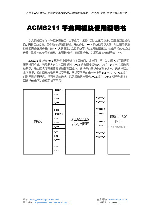
ACM8211模块给FPGA开发板提供千兆以太网接口,该接口由千兆以太网PHY和网络变压器接口组成。
当需要发送以太网数据时,FPGA把数据发送给PHY芯片,PHY芯片将数据编码后,通过网络变压器将数据加载到网线上。
数据经由网络传递到接收方。
远端发送过来的数据,经由网线传递给网络变压器,网络变压器的输出连接到PHY芯片上,PHY芯片对信号进行解码后,得到实际的数据,然后将数据传递给FPGA芯片。
FPGA实现千兆以太网数据传输的功能框图如下所示:RTL8211是一款支持GMII、RGMII、MII接口的以太网物理层收发器,能够工作在100M Base或1000M Base模式。
接口可设置为GMII、RGMII、MII接口。
并提供了若干引脚用于配置工作模式。
ACM8211模块默认使用GMII接口,实现该配置的方法是将对应的配置引脚E_COL(对,就是这个引脚,芯片在上电时会检测该引脚的状态,并根据该引脚的状态确定工作模式,正常工作时又是正常的COL功能)通过10K的电阻接到GND。
针对工程师用户,如果确实希望在使用RGMII接口,可以将R21焊接为10K电阻,将R25断开。
以太网物理层芯片都有一个器件地址,该地址可通过外部引脚设置,上图中,R20、R21、R24通过连接到VCC或者GND,决定了芯片的器件地址为001b。
当然,这些状态也仅在芯片上电时刻被读取,当芯片正常工作后,这些引脚就又恢复了普通功能。
AC6102 开发板千兆以太网UDP传输实验ACM8211模块设计实现了一路GMII接口的千兆以太网电路,通过该以太网电路,用户可以将FPGA采集或运算得到的数据传递给其他设备如PC或服务器,或者接收其他设备传输过来的数据并进行处理。
MAXIM MAX8211 MAX8212 说明书
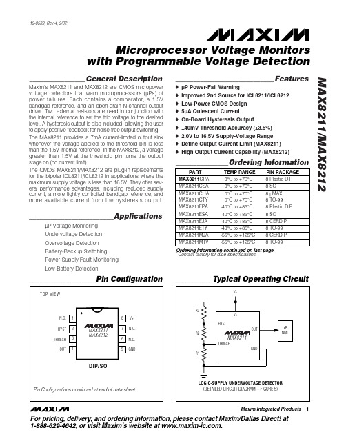
________________General DescriptionMaxim’s MAX8211 and MAX8212 are CMOS micropower voltage detectors that warn microprocessors (µPs) of power failures. Each contains a comparator, a 1.5V bandgap reference, and an open-drain N-channel output driver. Two external resistors are used in conjunction with the internal reference to set the trip voltage to the desired level. A hysteresis output is also included, allowing the user to apply positive feedback for noise-free output switching.The MAX8211 provides a 7mA current-limited output sink whenever the voltage applied to the threshold pin is less than the 1.5V internal reference. In the MAX8212, a voltage greater than 1.5V at the threshold pin turns the output stage on (no current limit).The CMOS MAX8211/MAX8212 are plug-in replacements for the bipolar ICL8211/ICL8212 in applications where the maximum supply voltage is less than 16.5V. They offer sev-eral performance advantages, including reduced supply current, a more tightly controlled bandgap reference, and more available current from the hysteresis output.________________________ApplicationsµP Voltage Monitoring Undervoltage Detection Overvoltage Detection Battery-Backup Switching Power-Supply Fault Monitoring Low-Battery Detection____________________________Featureso µP Power-Fail Warningo Improved 2nd Source for ICL8211/ICL8212o Low-Power CMOS Design o 5µA Quiescent Currento On-Board Hysteresis Output o ±40mV Threshold Accuracy (±3.5%)o 2.0V to 16.5V Supply-Voltage Range o Define Output Current Limit (MAX8211)o High Output Current Capability (MAX8212)_______________Ordering InformationMAX8211/MAX8212Microprocessor Voltage Monitors with Programmable Voltage Detection________________________________________________________________Maxim Integrated Products 1___________________Pin Configuration___________Typical Operating Circuit19-0539; Rev 4; 9/02Ordering Information continued on last page.*Contact factory for dice specifications.For pricing, delivery, and ordering information,please contact Maxim/Dallas Direct!at 1-888-629-4642, or visit Maxim’s website at .M A X 8211/M A X 8212Microprocessor Voltage Monitorswith Programmable Voltage Detection 2_______________________________________________________________________________________Supply Voltage.......................................................-0.5V to +18V Output Voltage.......................................................-0.5V to +18V Hysteresis...................+0.5V to -18V with respect to (V+ + 0.5V)Threshold Input Voltage...............................-0.5V to (V+ + 0.5V)Current into Any Terminal.................................................±50mA Continuous Power Dissipation (T A = +70°C)8-Pin Plastic DIP (derate 9.09mW/°C above +70°C).....727mW 8-Pin SO (derate 5.88mW/°C above +70°C)..................471mW8-Pin CERDIP (derate 8.00mW/°C above +70°C)..........640mW 8-Pin TO-99 (derate 6.67mW/°C above +70°C).............533mW Operating Temperature RangesMAX821_C_ _.......................................................0°C to +70°C MAX821_E_ _.....................................................-40°C to +85°C MAX821_M_ _..................................................-55°C to +125°C Storage Temperature Range.............................-65°C to +150°C Lead Temperature (soldering, 10s).................................+300°CStresses beyond those listed under “Absolute Maximum Ratings” may cause permanent damage to the device. These are stress ratings only, and functional operation of the device at these or any other conditions beyond those indicated in the operational sections of the specifications is not implied. Exposure to absolute maximum rating conditions for extended periods may affect device reliability.ABSOLUTE MAXIMUM RATINGSELECTRICAL CHARACTERISTICS(V+ = 5V, T= +25°C, unless otherwise noted.)MAX8211/MAX8212Microprocessor Voltage Monitors with Programmable Voltage Detection________________________________________________________________________________________3Note 1:The maximum output current of the MAX8211 is limited by design to 30mA under any operating condition. The output voltagemay be sustained at any voltage up to +16.5V as long as the maximum power dissipation of the device is not exceeded.Note 2:The maximum output current of the MAX8212 is not defined, and systems using the MAX8212 must therefore ensure that theoutput current does not exceed 50mA and that the maximum power dissipation of the device is not exceeded.ELECTRICAL CHARACTERISTICS (continued)(V+ = 5V, T A = +25°C, unless otherwise noted.)PARAMETER SYMBOL CONDITIONSUNITSI OUT = 2mA, V TH = 1.0V 0.170.4Output Saturation Voltage V OL I OUT = 2mA, V TH = 1.3V 0.170.4V V TH = 1.0V (Note 1)47.0Maximum Available Output CurrentI OHC temp. range,V OUT = 5VV TH = 1.3V (Note 2)1235mAT A = TMIN to T MAX , C/E temp. ranges, V+ = 16.5V, V TH = 1.0V,V HYST = -16.5V with respect to V+0.10.1Hysteresis Leakage CurrentI LHYST A = T MIN to T MAX , M temp. range, V+ = 16.5V, V TH = 0.9V,V HYST = -16.5V with respect to V+33µAHysteresis Saturation VoltageV HYS (MAX)I HYST = 0.5mA, V TH = 1.3V,measured with respect to V+-0.1-0.2-0.1-0.2V Maximum Available Hysteresis CurrentV HYS (MAX)V TH = 1.3V, V HYS = 0V210210mAMAX8212MIN TYP MAXMAX8211MIN TYP MAX _______________Detailed DescriptionAs shown in the block diagrams of Figures 1 and 2, the MAX8211 and MAX8212 each contain a 1.15V refer-ence, a comparator, an open-drain N-channel output transistor, and an open-drain P-channel hysteresis out-put. The MAX8211 output N-channel turns on when the voltage applied to the THRESH pin is less than the internal reference (1.15V). The sink current is limited to 7mA (typical), allowing direct drive of an LED without a series resistor. The MAX8212 output turns on when the voltage applied to THRESH is greater than the internal reference. It is not current limited, and will typically sink 35mA.Compatibility with ICL8211/ICL8212The CMOS MAX8211/MAX8212 are plug-in replacements for the bipolar I CL8211/I CL8212 in most applications.The use of CMOS technology has several advantages.The quiescent supply current is much less than in the bipolar parts. Higher-value resistors can also be usedFigure 1. MAX8211 Block DiagramM A X 8211/M A X 8212Microprocessor Voltage Monitorswith Programmable Voltage Detection 4_______________________________________________________________________________________Figure 3. Basic Overvoltage/Undervoltage Circuitin the networks that set up the trip voltage, since the comparator input (THRESH pin) is a low-leakage MOSFET transistor. This further reduces system current drain. The tolerance of the internal reference has also been significantly improved, allowing for more precise voltage detection without the use of potentiometers.The available current from the HYST output has been increased from 21µA to 10mA, making the hysteresis feature easier to use. The disparity between the HYST output and the voltage required at THRESH to switch the OUT pin has also been reduced in the MAX8211from 8mV to 0.1mV to eliminate output “chatter” or oscillation.Most voltage detection circuits operate with supplies of 15V or less; in these applications, the MAX8211/MAX8212 will replace I CL8211/I CL8212s with the per-formance advantages described above. However, note that the CMOS parts have an absolute maximum sup-ply-voltage rating of 18V, and should never be used in applications where this rating could be exceeded.Exercise caution when replacing I CL8211/ICL8212s in closed-loop applications such as programmable zeners. Although neither the I CL8211/I CL8212 nor the MAX8211/MAX8212 are internally compensated, the CMOS parts have higher gain and may not be stable for the external compensation-capacitor values used in lower-gain ICL8211/ICL8212 circuits.__________Applications InformationBasic Voltage DetectorsFigure 3 shows the basic circuit for both undervoltage detection (MAX8211) and overvoltage detection (MAX8212). For applications where no hysteresis is needed, R3 should be omitted. The ratio of R1 to R2 is then chosen such that, for the desired trip voltage at V IN ,1.15V is applied to the THRESH pin. Since the com-parator inputs are very low-leakage MOSFET transis-tors, the MAX8211/MAX8212 can use much higherresistors values in the attenuator network than can the bipolar I CL8211/I CL8212. See Table 1 for switching delays.Table 1. Switching DelaysVoltage Detectors with HysteresisTo ensure noise-free output switching, hysteresis is frequently used in voltage detectors. For both the MAX8211 and MAX8212 the HYST output is on for threshold voltages greater than 1.15V. R3 (Figure 3)controls the amount of current (positive feedback) sup-plied from the HYST output to the mid-point of the resis-tor divider, and hence the magnitude of the hysteresis,or dead-band.Figure 2. MAX8212 Block DiagramCalculate resistor values for Figure 3 as follows:1)Choose a value for R1. Typical values are in the 10k Ω to 10M Ω range.2)Calculate R2for the desired upper trip point Vusing the formula:3)Calculate R3 for the desired amount of +Figure 5 shows an alternate circuit, suitable only when thevoltage being detected is also the power-supply voltage for the MAX8211 or MAX8212.Calculate resistor values for Figure 5 as follows:1)Choose a value for R1. Typical values are in the 10k Ω to 10M Ω range.2)Calculate R2:3)Calculate R3:Low-Voltage Detector for Logic SupplyThe circuit of Figure 5 will detect when a 5.0V (nominal)supply goes below 4.5V, which is the V MIN normally specified in logic systems. The selected resistor values ensure that false undervoltage alarms will not be gener-ated, even with worst-case threshold trip values and resistor tolerances. R3 provides approximately 75mV of hysteresis.MAX8211/MAX8212Microprocessor Voltage Monitors with Programmable Voltage Detection________________________________________________________________________________________5Figure 4. MAX8211/MAX8212 Threshold Trip Voltage vs.Ambient TemperatureFigure 5. MAX8211 Logic-Supply Low-Voltage DetectorM A X 8211/M A X 8212Microprocessor Voltage Monitorswith Programmable Voltage Detection 6________________________________________________________________________________________Ordering Information (continued)_____________________________________________Pin Configurations (continued)*Contact factory for dice specifications.MAX8211/MAX8212Microprocessor Voltage Monitors with Programmable Voltage Detection_______________________________________________________________________________________7Package Information(The package drawing(s) in this data sheet may not reflect the most current specifications. For the latest package outline information,go to /packages .)M A X 8211/M A X 8212Microprocessor Voltage Monitorswith Programmable Voltage Detection 8_______________________________________________________________________________________Package Information (continued)(The package drawing(s) in this data sheet may not reflect the most current specifications. For the latest package outline information,go to /packages .)MAX8211/MAX8212Microprocessor Voltage Monitors with Programmable Voltage Detection_______________________________________________________________________________________9Package Information (continued)(The package drawing(s) in this data sheet may not reflect the most current specifications. For the latest package outline information,go to /packages .)Ma xim ca nnot a ssume responsibility for use of a ny circuitry other tha n circuitry entirely embodied in a Ma xim product. No circuit pa tent licenses a re implied. Maxim reserves the right to change the circuitry and specifications without notice at any time.10__________________Maxim Integrated Products, 120 San Gabriel Drive, Sunnyvale, CA 94086 (408) 737-7600©2002 Maxim Integrated ProductsPrinted USAis a registered trademark of Maxim Integrated Products.M A X 8211/M A X 8212Microprocessor Voltage Monitorswith Programmable Voltage DetectionPackage Information (continued)(The package drawing(s) in this data sheet may not reflect the most current specifications. For the latest package outline information,。
rtl8211f硬件设计
rtl8211f硬件设计rtl8211f硬件设计【简介】rtl8211f是Realtek(瑞昱)公司推出的一款集成电路芯片,主要用于局域网(LAN)接口的物理层连接。
它提供了高速、高性能的以太网连接解决方案,适用于各种网络设备,如计算机、路由器、交换机等。
【硬件设计】rtl8211f的硬件设计包括电源设计、物理层接口设计和其他外设设计等方面。
一、电源设计rtl8211f的电源设计应符合以下要求:1. 稳定性:为确保芯片正常工作,电源必须提供稳定的直流电压。
2. 电源电压:rtl8211f的推荐电源电压为3.3V。
3. 电流需求:根据实际使用情况,计算出芯片的平均和峰值电流需求,合理设计电源的容量。
4. 滤波和稳压:在电源输入端和芯片之间添加适当的电源滤波电路和稳压电路,以减小电源噪声的影响。
二、物理层接口设计rtl8211f的物理层接口设计应考虑以下因素:1. 电气特性:确保与其他设备的电气接口兼容。
2. 接口标准:rtl8211f支持多种以太网标准,如10BASE-T、100BASE-TX和1000BASE-T。
根据实际需求选择适当的标准接口。
3. 连接器:根据电气接口标准选择合适的接口连接器,如RJ-45。
确保连接器与芯片的引脚对应正确。
4. 信号完整性:考虑信号线的长度和布线方式,确保信号的完整性和稳定性。
可以采用阻抗匹配、差分信号传输等方法提高信号质量。
5. 反射和串扰:对于高速传输的信号线,要防止信号反射和串扰。
可以采用终端电阻、屏蔽和布线分离等方法减小这些影响。
三、其他外设设计rtl8211f作为一个局域网接口芯片,还需要与其他外设进行连接,如MAC控制器和PHY控制器。
1. MAC控制器接口:rtl8211f的MAC控制器通常通过GMII(Gigabit Media Independent Interface)或RGMII(Reduced Gigabit Media Independent Interface)与PHY控制器连接。
IT8211直流电子负载使用者手册说明书
Digital ControlElectronic loadUser ’s ManualIT8211 直流電子負載使用者手冊全方位電源解決方案供應商版權所有 © 艾德克斯電子有限公司声明© Itech Electronics, Co., Ltd. 2014根据国际版权法,未经 Itech Electronics, Co., Ltd. 事先允许和书面同意,不得以任何形式(包括电子存储和检索或翻译为其他国家或地区语言)复制本手册中的任何内容。
手册部件号IT8211-402194版本第1版, 2014 年 11月 28 日发布Itech Electronics, Co., Ltd. 商标声明Pentium是 Intel Corporation在美国的注册商标。
Microsoft、Visual Studio、Windows 和 MS Windows是Microsoft Corporation 在美国和 /或其他国家 /地区的商标。
担保本文档中包含的材料 “按现状 ”提供,在将来版本中如有更改,恕不另行通知。
此外,在适用法律允许的最大范围内,ITECH 不承诺与本手册及其包含的任何信息相关的任何明示或暗含的保证,包括但不限于对适销和适用于某种特定用途的暗含保证。
ITECH对提供、使用或应用本文档及其包含的任何信息所引起的错误或偶发或间接损失概不负责。
如 ITECH与用户之间存在其他书面协议含有与本文档材料中所包含条款冲突的保证条款,以其他书面协议中的条款为准。
技术许可本文档中描述的硬件和/或软件仅在得到许可的情况下提供并且只能根据许可进行使用或复制。
限制性权限声明美国政府限制性权限。
授权美国政府使用的软件和技术数据权限仅包括那些定制提供给最终用户的权限。
ITECH 在软件和技术数据中提供本定制商业许可时遵循 FAR 12.211(技术数据)和 12.212(计算机软件)以及用于国防的 DFARS252.227-7015(技术数据-商业制品)和 DFARS 227.7202-3(商业计算机软件或计算机软件文档中的权限)。
常见USB无线网卡的芯片型号

Tenda W311Ma
Belkin F7D1101 v2
D-Link DWA-123 rev A1
特点:USB 2.0、bgn、1x1:1、2010-06-24
使用RT3070的网卡:
JCG JHL-N132R
D-Link DWA-131 rev B1
D-Link DWA-132
D-Link DWA-133
D-Link DWA-135
Netgear WNA3100M
TP-LINK TL-WN8200ND
TP-LINK TL-WN821N v4
TP-LINK TL-WN822N v3
TP-LINK TL-WN823N v1
常见usb无线网卡的芯片型号使用ar9271芯片的网卡
常见USB无线网卡的芯片型号
使用AR9271芯片的网卡:
D-Link DWA-126
Netgear WNA1100
TP-LINK TL-WN721N 1x1:1
TP-LINK TL-WN722N 1x2:1
OPPO Digital AK093 1x1:1(TPLINK制造)
使用RTL8188CUS的网卡:1*1:1 bgn
Asus USB-N10 Nano
D-Link DW
Haoliyuan (Shenzhen) Electronic WU110EC
Netgear WNA1000M
TP-LINK TL-WN723N v2
TP-LINK TL-WN725N v2
TP-LINK TL-WN727N v4 (CN?)
TP-LINK TL-WN725N v1
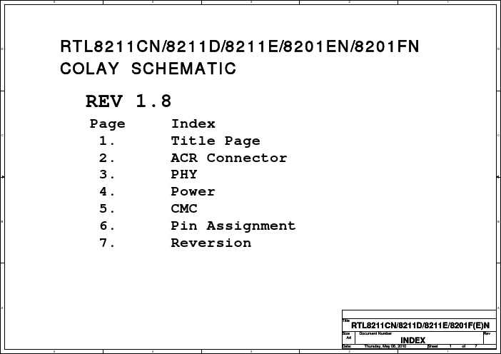
RTL8211CN_8211D_8211E_8201EN参考设计V1.8
JA1 TX_CTL COL_N CRS_N TX_CLK TXD0 TXD1 TXD2 TXD3 PCIRST TXER TX_CTL COL_N CRS_N TX_CLK TXD0 TXD1 TXD2 TXD3 PCIRST TXER A40 A39 A38 A37 A36 A35 A34 A33 A32 A31 A30 A29 A28 A27 A26 A25 A24 A23 A22 A21 A20 A19 A18 A17 A16 A15 A14 A13 A12 A11 A10 A9 A8 A7 A6 A5 A4 A3 A2 A1 TXCTL COL CRS DGND TXCLK DGND TXD0 TXD1 DGND TXD2 TXD3 RESET TXER PWRDWN NC13 DGND NC12 DGND NC11 DGND 25MHz DGND NC10 NC9 DGND NC8 NC7 DGND NC6 NC5 DGND NC4 NC3 DGND NC2 2.5V DGND NC0 +3.3 DVDD +5V Digital MiniJA MDIO MDC RXER RXCTL DGND RXD0 RXD1 RXD2 RXD3 DGND RXCLK INT NC33 NC32 NC31 NC30 PME DGND CLK125 DGND NC27 DGND NC26 NC25 DGND NC24 NC23 DGND NC22 NC21 DGND NC20 NC19 DGND NC18 2.5V NC16 NC15 +3.3 DVDD +5V Digital B40 B39 B38 B37 B36 B35 B34 B33 B32 B31 B30 B29 B28 B27 B26 B25 B24 B23 B22 B21 B20 B19 B18 B17 B16 B15 B14 B13 B12 B11 B10 B9 B8 B7 B6 B5 B4 B3 B2 B1 MDIO MDC RXER_N RX_CTL_N RXD0_N RXD1_N RXD2_N RXD3_N RX_CLK_N INT MDIO MDC RXER_N RX_CTL_N RXD0_N RXD1_N RXD2_N RXD3_N RX_CLK_N INT
8211是数模拟转换芯片

8211是数模拟转换芯片,通过8211转换出来左、右声道的两路音频信号,再由采用双运放4558构成的音频放大电路分别进行放大。
【有的机顶盒没有采用4558】。
8211的脚跟能如下:1:BCK 1.7V2: WS 1.7V3: DIN 0V4: GND 0V8: RCH 1.7V7: NC 3V6: LCH 1.7V5: VDD 4.8V有的机芯实际使用只有6脚输出。
7脚,8脚空【测量红,白音频输出直通的基本不使用4558】。
有的使用6脚8脚的,是有左右声道的【红,白音频输出不通的基本使用4558】。
以上电压为实测。
部分出入不大。
供产考。
实际维修中:如没有伴音输出,在确认4558完好的情况下,请测量8211各脚电压。
或者直接更换。
如果4558损坏。
又没有配件代换的可以从8211的8脚串个103瓷片电容到AUDIO以上办法只供产考![color=chocolate][/color]下面是4558资料文章出处:LCDHOME论坛网原文地址:运放集成电路MC4558引脚功能及代换MC4558是双运放,增益高,噪音低,适用于音响前置放大级、有源滤波器以及其他电子线路中。
推荐工作电压±15V。
当Rl≥lk,输出电压Vo=±IOV时,增益86~100dB。
MC4558采用8脚双列直插封装。
各引脚功能是:①输出I,②反向输入I,③正向输入I,④-Vcc,⑤正向输入Ⅱ,⑥反向输入Ⅱ,⑦输出Ⅱ,⑧+Vcc。
MC4558可代换的型号较多,可用相同封装的下列型号直接代换,如:NE4558D,NJM4558,RC4558P,uPC4558,uA4558,LA6458,BA4558,TA75558P,CA1458E等PT8211是一条双工通道,16位运用CMOS技术的数模转换器集成电路speciallydesigned为数字式音频应用。
内部转换建筑学根据R-2Rresister梯子网络,内部电路是搭配得不错的,并且一个16位力学范围达到甚而全电源电压范围。
思科 8811、8841、8851 和 8861 IP 电话用户指南

Cisco IP 电话 8811、8841、8851 和 8861 用户指南(用于 Cisco Unified Communications Manager 10.5)首次发布日期: 2014年09月05日上次修改日期: 2014年09月09日Americas HeadquartersCisco Systems, Inc.170 West Tasman DriveSan Jose, CA 95134-1706USATel: 408 526-4000800 553-NETS (6387)Fax: 408 527-0883本手册中有关产品的规格和信息如有更改,恕不另行通知。
本手册中的所有陈述、信息和建议被认为是准确的,但我们不提供任何形式的明示或暗示担保。
用户必须自行负责对任何产品的应用。
软件许可证和产品的有限保修单在产品随附的信息包中皆有说明,并作为参考文件列入此处。
如果您找不到软件许可证或有限保修单,请联系CISCO销售代表获取一份。
以下信息涉及A类设备的FCC遵从性:经测试,本设备符合FCC规则第15部分对A类数字设备的限制规定。
这些限制旨在提供合理的保护,防止设备在商业环境中运行时产生有害干扰。
本设备可以产生、利用并发射无线射频能量。
如果不按说明中的要求安装和使用本设备,有可能对无线电通信产生有害干扰。
在居民区运行此设备可能会造成有害干扰,在这种情况下,用户需要自费消除干扰。
以下信息涉及B类设备的FCC遵从性:经测试,本设备符合FCC规则第15部分对B类数字设备的限制规定。
设置这些限制的目的是在设备安装于居所时,提供合理保护以避免干扰。
本设备可以产生、利用并发射无线射频能量。
如果不按说明中的要求安装和使用本设备,有可能对无线电通信产生有害干扰。
不过,我们不能保证在任何安装中都不会产生干扰。
如果本设备确实对无线电或电视接收造成干扰(可以通过打开和关闭设备来确定),建议用户采取以下一种或多种措施来消除干扰:•重新调整接收天线的方向或位置。
ITA-2111系列Intel AtomTM E3845无风扇1U上架式系统 快速入门手册说明书

ITA-2111快速入门手册 1安装系统之前,用户需确认包装中含有本设备以及下面所列各项:1. 1 x ITA-2111系列IPC2. 1 x ITA-2111配件盒3. 1 x ITA-2111质保卡注:阅读PDF文件需要使用Acrobat Reader。
用户可从以下路径下载Acrobat Reader:/Products/acrobat/readstep2.html(Acrobat为Adobe公司的商标)ITA-2111系列 Intel® Atom™ E3845无风扇1U 上架式系统快速入门手册标准功能• 芯片和芯片组:Intel Atom TM E3845 处理器• BIOS:AMI SPI 64 Mb• 内存:板载4 GB DDR3L 1333内存• 显示:Intel Gen 7,频率542 MHz, 共享系统内存为256 MB SDRAM • 双显模式:单显分辨率可达VGA 2560x1600,DVI 1920x1200, 1 x VGA、1 x DVI-D • 存储:- 1 x 3.5”HDD或2 x 2.5”HDD - 1 x 全长mSATA • 扩展槽: - 1 x PCI104- 1 x Mini PCIe插槽系统规格• 以太网:4 x 10/100/1000M以太网• USB:1 x USB 3.0、6 x USB 2.0• 显示:1个VGA接口,1个DVI-D接口• 串口:2个DB9端口,8个20针端子排,支持RS-232/422/485切换• CAN端口:2 x CAN• 音频:1个扬声器输出接口(支持2x4W扬声器)1个麦可输入接口• PS/2: 1 x PS/2机械与环境规格• 产品尺寸(W x H x D):427 x 44 x 325 mm• 电源输入:AC 100-240或DC 110V • 工作温度:- 0 - 40°C(32 ~ 104°F,带HDD) - -25 - 60°C(-13 ~ 140°F,带SSD)• 净重:7.7 kg如需了解有关本产品及研华其它产品的详细信息,请访问我们的网站:/eplatform如需技术服务与支持,请访问我们的技术支持网站: 本手册适用于ITA-2111系列。
VSC8211 链接 CPU 与 R GMII 接口的 SGMII 基础交换机说明书

VSC8211 Linking CPUs with R/GMII Interfaces to SGMII-BasedSwitches1Revision History (1)1.1Revision 1.0 (1)2Introduction (2)2.1Audience (2)2.2References (2)2.2.1Vitesse Documents (2)2.2.2IEEE Standards (2)2.2.3External Documents (2)3 A Managed Switch System (3)4System Considerations (4)4.1How Many Interface Ports? (4)4.2Packet Traffic Shaping (4)4.3RGMII-SGMII PHY Device Link Monitoring (4)5Hardware Considerations (5)5.1Connecting GMII (5)5.2Connecting RGMII (6)5.3Connecting SGMII (7)5.4Control and Status Connections (7)6Software Considerations (9)6.1VSC8211 Register Configuration (9)6.2SGMII Switch Register Configuration (9)1Revision HistoryThe revision history describes the changes that were implemented in the document. The changes arelisted by revision, starting with the most current publication.1.1Revision 1.0Revision 1.0 was the first release of this document. It was published in April 2005.2IntroductionThis Application Note will describe design considerations for connecting an embedded microprocessorthat contains a GMII or RGMII MAC interface to an SGMII-based Gigabit Ethernet Switch. This documentwill cover system, hardware, and software considerations as well as advantages and limitations for each.Systems such as IP DSLAMs, wireless platforms, and enterprise routers often require enhanced securityprotocol processors to help to perform switching and parsing of packets. However, packet processors’Ethernet interfaces are a generation behind the latest Ethernet switch devices. The latest GigabitEthernet switch devices with high port counts of 16-24 ports per chip have migrated towards SGMIIinterfaces, while processors are only now offering both GMII and RGMII interfaces. For a packetprocessor to connect to the latest gigabit switch, there will need to be an interface conversion device toget an RGMII processor to link to an SGMII-based Ethernet switch. This document will cover variousdesign considerations for connecting an embedded microprocessor with a GMII or RGMII MAC interfaceto an SGMII-based Gigabit Ethernet switch. This document will address system, hardware, and softwareconsiderations as well as advantages and limitations for each.2.1AudienceThis document is geared toward system, hardware, and software designers.2.2References2.2.1Vitesse DocumentsVSC8211 Datasheet (VMDS-10105)VSC8224 Datasheet (VMDS-10107)VSC7372 Datasheet (PD0031)VSC7374 Datasheet (PD0028)VSC7376 Datasheet (PD0032)VSC8211 Design and Layout Guide (VPPD-01173)VSC8224 Design and Layout Guide (VPPD-01145)2.2.2IEEE StandardsCSMA/CD Access Method and Physical Layer Specification (IEEE802.3)2.2.3External DocumentsFreescale MPC8548E Fact Sheet (MPC8548FS)Intel IXP2325 Product Brief (30367902)AMCC PowerPC 440GX Product Brief (PB2000)Mindspeed M27481 Product Brief (27481-BRF)3 A Managed Switch SystemA managed switch system is composed of at least an Ethernet switch chip, several physical layer devices(PHYs) that can interface to copper or fiber links, and at least one embedded processor. The system willgenerally be responsible for managing packets at a level of up to Layer 3 or higher.Figure 1 • Managed Switch Block Diagram4.1How Many Interface Ports?One factor to consider is how many interface ports from the switch will be connected to the embeddedprocessor. For example, the MPC8548E PowerQuicc III has four-gigabit Ethernet MAC interfaces. All fourof these ports could be linked to the Ethernet switch.4.2Packet Traffic ShapingGenerally a gigabit Ethernet connection requires at least 1 GHz of dedicated CPU processing power.Most embedded processors cannot handle a large continuous burst of packet data of this magnitude. Toprevent a processor from being overrun, it is important to consider if traffic shaping will be required.Traffic shaping is useful in that it can limit the amount of egress traffic from being sent out of a switchport into a bandwidth-limited device, such as a CPU.4.3RGMII-SGMII PHY Device Link MonitoringTo ensure the link between the processor and switch is active, there are several monitoring methods toconsider.The PHY’s link status register bit can be continuously polled.The PHY’s interrupt pin is connected to the interrupt controller to monitor change in link status.The LINK LED can be connected to a GPIO pin on the processor and then this pin is monitored.5Hardware ConsiderationsOnce the number of ports is established, the RGMII-SGMII conversion device must be selected. For 1-2ports, the VSC8211 single gigabit PHY can be used. For higher ports, the VSC8224 quad gigabit PHY is abetter choice due to its compact footprint size and low power.The following information in this section is a general description. Please consult both the PHY’sdatasheet or design and layout guide for more specific design information.Figure 2 • RGMII-to-SGMII Hardware Connectivity5.1Connecting GMIIGMII is a 25-pin per port interface. It has a clock speed of 125 MHz and 8 data bits in both directions.The interface clock is sourced by the PHY.Figure 3 • GMII Connection Diagram5.2Connecting RGMIIRGMII is a reduced pin count version of GMII as it only has 12 pins per port. While it uses the same 125MHz clock speed, the data pin count is reduced to 4 bits and the data is clocked in on both edges of theclock in a double-data rate manner.Figure 4 • RGMII Connection DiagramAnother aspect of RGMII that is different from GMII is that it requires a clock delay skew of 1.5 ns–1.9 nsAnother aspect of RGMII that is different from GMII is that it requires a clock delay skew of 1.5 ns–1.9 nsto either be placed on the board with a delay trace or the delay is created internally in the MAC and/orPHY. The VSC8211 offers this clock delay skew feature on both TX and RX pairs thereby removing theneed for a board trace delay. See the VSC8211 or VSC8224 Design and Layout Guide for moreinformation.5.3Connecting SGMIISGMII is a further pin reduction of GMII as it is only a 4-pin interface. The data and clock are embeddedand transmitted on a two pin differential interface in both directions. The latest switch will operate itsport interface using the SGMII interface. Both the VSC8211 and VSC8224 cannot perform a full RGMII-to-SGMII conversion. These devices however, can operate as an RGMII-to-1000BASE-X SerDes mediaconverter. 1000BASE-X SerDes is compliant electrically and functionally to SGMII’s 1000 Mbps setting.From a permanent link perspective, 1000 Mbps is the only speed that is required in an SGMII-basedEthernet switch system. Therefore the RGMII-to-1000BASE-X mode can be used to link the processor tothe SGMII-based Ethernet switch.For the VSC8211/VSC8224, AC coupling capacitors are needed from the processor to the PHY. The SGMIIswitches such as the VSC7372/74/76 have a register setting to allow the PHY-to-Switch portion to beelectrically compatible. To allow the SerDes on the PHY to link, the SIGDET pin must also be asserted bytying it high.Figure 5 • SGMII Connection Diagram5.4Control and Status ConnectionsIn order to setup the PHY the MDC and the MDIO must be connected to the host processor to setup theoperating mode and other PHY register settings. Also depending on how the processor will monitor thePHY during normal operation, other pins such as the interrupt pin (MDINT) or the LINK LED pin will needto be connected.Figure 6 • Control and Status Diagram6.1VSC8211 Register ConfigurationFor the VSC8211, the following registers must be configured.Set the operating mode (see the following table).If using RGMII, then set the delay skew setting (register 23[11:8]).Set Auto-negotiation Disabled (Register 0.12 = 0).Set Speed Selection (Register 0.[6,13] = 10).Set Duplex to Full (Register 0.8 = 1).If using MDINT pin as a link indication, set Register 25.15 = 1 and Register 25.13 = 1 (Link statechange indication).Table 1 • Setting the VSC8211 Operating Mode (Register 23[15:12, 2:1])Register Setting Description0011 01GMII-Fiber (1000BASE-X SerDes)0001 01RGMII-Fiber (1000BASE-X SerDes)6.2SGMII Switch Register ConfigurationFor the VSC7372/74/76 switch, the following registers must be configured in order to link to theVSC8211. This is in addition to the settings that are required for initialization of the switch. Thesesettings can be found in the Minimum Software Requirements section of the VSC7372/74/76datasheets.Set the SGMII_MACRO_CFGx.TX_ENA (Block 1, 0x1A bit 28 = 1)Set the SGMII_MACRO_CFGx.TX_OUTPUT_LEVEL (Block 1, 0x1A bit 26 = 1)Set the SGMII_MACRO_CFGx.TX_RESET (Block 1, 0x1A bit 25 = 1)Set the SGMII_MACRO_CFGx.RX_IB_AUTO_SQUELCH (Block 1, 0x1A bit 24 = 1)Set the SGMII_MACRO_CFGx.TX_COMMONMODE_TERM_ENA (Block 1, 0x1A bit 23 = 1)Set the SGMII_MACRO_CFGx.CDR_DISABLE (Block 1, 0x1A bit 22 = 0)Set the SGMII_MACRO_CFGx.RX_ENA (Block 1, 0x1A bit 8 = 1)Set the SGMII_MACRO_CFGx.RX_RESET (Block 1, 0x1A bit 0 = 1)Set the SGMII_INPUT_COMMONMODE_SELx.IB_B (Block 1, 0x1B bit 9 = 1)Set the SGMII_INPUT_COMMONMODE_SELx.IB_A (Block 1, 0x1B bit 0 = 1)Also, if traffic shaping is being employed, this can be found in the following table.Table 2 • Switch Egress Port Traffic Shaping ControlRegister Setting Register DescriptionWS_CONFx.ENABLE Block 1, 0x28 bit 6Enables/Disables ShapingWS_CONFx Block 1, 0x28 bits 12:7, 5:0Configures the ShapingWS_BUCK0Block 1, 0x29 bits 20:0Configures Queue 0 BucketWS_BUCK1Block 1, 0x2A bits 20:0Configures Queue 1 BucketWS_BUCK2Block 1, 0x2B bits 20:0Configures Queue 2 BucketWS_BUCK3Block 1, 0x2C bits 20:0Configures Queue 3 BucketMicrosemi HeadquartersOne Enterprise, Aliso Viejo,CA 92656 USAWithin the USA: +1 (800) 713-4113Outside the USA: +1 (949) 380-6100Sales: +1 (949) 380-6136Fax: +1 (949) 215-4996Email:***************************© 2005 Microsemi. All rights reserved. Microsemi and the Microsemi logo are trademarks of Microsemi Corporation. All other trademarks and service marks are the property of their respective owners.Microsemi makes no warranty, representation, or guarantee regarding the information contained herein or the suitability of its products and services for any particular purpose, nor does Microsemi assume any liability whatsoever arising out of the application or use of any product or circuit. The products sold hereunder and any other products sold by Microsemi have been subject to limited testing and should not be used in conjunction with mission-critical equipment or applications. Any performance specifications are believed to be reliable but are not verified, and Buyer must conduct and complete all performance and other testing of the products, alone and together with, or installed in, any end-products. Buyer shall not rely on any data and performance specifications or parameters provided by Microsemi. It is the Buyer's responsibility to independently determine suitability of any products and to test and verify the same. The information provided by Microsemi hereunder is provided "as is, where is" and with all faults, and the entire risk associated with such information is entirely with the Buyer. Microsemi does not grant, explicitly or implicitly, to any party any patent rights, licenses, or any other IP rights, whether with regard to such information itself or anything described by such information. Information provided in this document is proprietary to Microsemi, and Microsemi reserves the right to make any changes to the information in this document or to any products and services at any time without notice.Microsemi, a wholly owned subsidiary of Microchip Technology Inc. (Nasdaq: MCHP), offers a comprehensive portfolio of semiconductor and system solutions for aerospace & defense, communications, data center and industrial markets. Products include high-performance and radiation-hardened analog mixed-signal integrated circuits, FPGAs, SoCs and ASICs; power management products; timing and synchronization devices and precise time solutions, setting the world's standard for time; voice processing devices; RF solutions; discrete components; enterprise storage and communication solutions; security technologies and scalable anti-tamper products; Ethernet solutions; Power-over-Ethernet ICs and midspans; as well as custom design capabilities and services. Microsemi is headquartered in Aliso Viejo, California, and has approximately 4,800 employees globally. Learn more at www. .VPPD-01208。
瑞昱RTL8211F-CG

瑞昱RTL8211F-CG瑞昱RTL8211F集成式千兆⽹卡芯⽚集成式10/100/1000M以太⽹精密收发器⼀般说明RTL8211F-CG/RTL8211FD-CG/RTL8211FS-CG/RTL8211FI-CG/RTL8211FDI-CGRealtekRTL8211F-CG/RTL8211FI-CG是⾼度集成的以太⽹收发器,兼容10Base-T,100Base-TX和1000Base-TIEEE802.3标准。
它提供了所有必要的物理层功能,以通过CAT.5UTP电缆发送和接收以太⽹数据包。
RTL8211FI-CG是根据⼯业标准制造的。
RTL8211F(I)-CG使⽤最新的DSP技术和模拟前端(AFE),可以通过UTP电缆发送和接收⾼速数据。
RTL8211F(I)-CG实现了诸如交叉检测和⾃动校正,极性校正,⾃适应均衡,串扰消除,回声消除,定时恢复和纠错等功能,以提供功能强⼤的10Mbps,100Mbps或1000Mbps的发送和接收功能。
MAC和PHY之间的数据传输是通过针对1000Base-T,10Base-T和100Base-TX的简化千兆媒体独⽴接⼝(RGMII)实现的。
RTL8211F(I)-CG⽀持各种RGMII信号电压,包括3.3V,2.5V,1.8V和1.5V。
RTL8211F(I)-CG集成了最新的开关稳压器,该开关稳压器需要精⼼设计的PCB布局以实现良好的电源效率并减少输出电压纹波和输⼊过冲。
特征与1000Base-TIEEE802.3ab兼容兼容100Base-TXIEEE802.3u兼容10Base-TIEEE802.3⽀持RGMII⽀持IEEE802.3az-2010(节能以太⽹)内置局域⽹唤醒(WOL)⽀持中断功能⽀持并⾏检测交叉检测和⾃动校正⾃动极性校正⽀持PHYRSTB内核电源关闭基线漂移校正在1000Base-T中⽀持CAT.5电缆120mRGMII的可选3.3/2.5/1.8/1.5V信令⽀持25MHz外部晶体或OSC为MAC提供125MHz的时钟源提供3个⽹络状态LED⽀持LinkDown节能绿⾊以太⽹(仅1000/100Mbps模式)内置开关稳压器40引脚QFN绿⾊封装55nm⼯艺,超低功耗⼯业级制造⼯艺(RTL8211FI-CG)应⽤领域DTV(数字电视)MAU(媒体访问单元)CNR(通信和⽹络提升器)游戏机打印机和办公机器DVD播放器和刻录机以太⽹集线器以太⽹交换机此外,RTL8211F(I)-CG可⽤于任何需要UTP物理连接的具有以太⽹MAC的嵌⼊式系统。
KX8211-AGN快速配置手册

802.11AGN快速配置 使用说明书1.产品介绍本产品系列高性能无线网络Access Po i n t(A P)和Bridge专为企业和公共接入设计,内置Atheros芯片组,可提供高性能的网络接入,高带宽。
支持高达300Mbps 的传输速率。
工作于多种不同的模式,适应于多种无线应用,包括长距离网络部署。
Bridge采用可扩展的分离式天线设计,适用于广泛的无线应用,同时允许你根据信号广播的强度,方便调节天线位置,从而提高无线链路距离和信号强度。
此外,整合的Power o v er Ethernet(PoE)设计允许将Bridge部署到电源不容易达到的地方。
为保护你的网络安全和秘密,AP使用多种方式来提高无线安全性能。
同样整合了独特的高级特性,使B r i d g e更适合进行远距离传输;2.接口介绍产品外观介绍说明1):馈线接口: 贰个N型接口,连接外部天线(双极化方式)2):供电接口:电缆连接器接口,,该模式下用于连接PoE模块3.硬件安装无线设备通过POE模块供电。
用屏蔽五类双绞线制作成直通线,将POE 模块的CABLE端口与无线设备的RJ-45端口相连(在制作此段网线时,需先将防水接头套上,再做水晶头);用屏蔽双绞线制作成交叉线,将POE模块的LAN端口与电脑终端相连。
如POE模块与交换机/集线器相连,则使用直通线。
由于有供电线路请务必保证双绞线的制作方法正确。
为了防止发生短路的情况,推荐在连接前使用测线器测试线路是否正常。
说明:z交叉线的制作 交叉线两端排线的颜色顺序是:一端: 白橙/橙/白绿/蓝/白蓝/绿/白棕/棕另一端:白绿/绿/白橙/蓝/白蓝/橙/白棕/棕 z直通线的制作 直通线两端排线的颜色顺序是:一端: 白橙/橙/白绿/蓝/白蓝/绿/白棕/棕另一端:白橙/橙/白绿/蓝/白蓝/绿/白棕/棕将电源线连接到电源适配器,将电源适配器的输出插到POE模块的电源插口。
保证线缆连接正确后,将电源线插头插到AC输出的插座上,给无线设备供电。
pt8211典型程序 -回复
pt8211典型程序-回复PT8211典型程序目录一、引言二、PT8211概述三、PT8211的使用方法1. 硬件连接2. 软件配置3. 初始化PT82114. 编写音频播放程序四、总结一、引言PT8211是一款数字音频ADC和DAC转换器,广泛应用于音频采集和音频播放等领域。
本文将介绍PT8211的概述,并以PT8211典型程序为主题,详细说明PT8211的使用方法。
二、PT8211概述PT8211是一款双声道24位音频ADC和DAC转换器,采用I2S接口进行数据传输,并能够通过I2C总线配置和控制。
其特点包括低噪音、低失真和高动态范围等。
PT8211可广泛应用于数字音频采集、音频播放、音频处理和音频录制等领域。
三、PT8211的使用方法1. 硬件连接首先,需要将PT8211与微控制器或数字音频处理器连接。
PT8211的硬件连接主要包括将I2S接口的SCK(时钟线)、WS(帧同步线)和SD(数据线)分别连接到微控制器或数字音频处理器的对应引脚,以及将PT8211的VCC(电源正极)和GND(地线)连接到电源供应器的正负极。
2. 软件配置在使用PT8211之前,需要进行相关软件配置,以便控制PT8211的参数和功能。
这通常涉及到使用I2C总线与PT8211进行通信。
需要根据具体的开发环境和平台,选择合适的I2C库和驱动程序进行配置。
3. 初始化PT8211在对PT8211进行操作之前,需要对其进行初始化。
这包括设置I2S接口的时钟频率、数据格式和传输模式等。
初始化PT8211旨在确保其能够正常工作并提供所需的音频信号质量。
4. 编写音频播放程序编写音频播放程序的目的是将音频数据传输给PT8211,并通过其将音频信号输出。
这需要将音频数据通过I2S接口的数据线传输给PT8211,并设置好音频采样率和数据格式。
最后,通过启动I2S接口的传输,将音频信号传送到PT8211,实现音频播放功能。
四、总结本文对PT8211的概述和使用方法进行了详细说明,并以PT8211典型程序为主题,一步一步回答了如何使用PT8211进行音频播放。
RTL8211D_DG_DN_DataSheet_1.2

RTL8211D-VB-GRRTL8211DG-VB-GRRTL8211DN-VB-GRINTEGRATED 10/100/1000MBPS ETHERNETTRANSCEIVERDATASHEET(CONFIDENTIAL: Development Partners Only)Rev. 1.213 August 2010Track ID: JATR-2265-11 Array Realtek Semiconductor Corp.No. 2, Innovation Road II, Hsinchu Science Park, Hsinchu 300, TaiwanTel.: +886-3-578-0211 Fax: +886-3-577-6047Integrated 10/100/1000Mbps Ethernet Transceiverii Track ID: JATR-2265-11 Rev. 1.2COPYRIGHT ©2010 Realtek Semiconductor Corp. All rights reserved. No part of this document may be reproduced, transmitted, transcribed, stored in a retrieval system, or translated into any language in any form or by any means without the written permission of Realtek Semiconductor Corp.DISCLAIMERRealtek provides this document “as is”, without warranty of any kind. Realtek may make improvements and/or changes in this document or in the product described in this document at any time. This document could include technical inaccuracies or typographical errors.TRADEMARKSRealtek is a trademark of Realtek Semiconductor Corporation. Other names mentioned in this document are trademarks/registered trademarks of their respective owners.LICENSEThis product is covered by one or more of the following patents: US5,307,459, US5,434,872, US5,732,094, US6,570,884, US6,115,776, and US6,327,625.USING THIS DOCUMENTThis document is intended for the software engineer’s reference and provides detailed programming information.Though every effort has been made to ensure that this document is current and accurate, more information may have become available subsequent to the production of this guide. REVISION HISTORYRevision Release Date Summary1.0 2010/04/28 First release.1.1 2010/08/09 Revised IEEE 802.3az to Draft3.2.Added section 3.7 UTP/Fiber Auto-Detection to GMII/RGMII Application Diagram(RTL8211DN), page 5.Revised Table 15 MII/MDI Interface Configuration, page 19.Added section 6.9 Green Ethernet (Gigabit Mode Only), page 20.Added section 6.10.6 Access to Extension Page (ExtPage), page 22.Added section 6.10.7 Access to MDIO Manageable Device (MMD), page 22.Revised Table 21 Page0 Register Mapping and Definitions, page 32.Added section 7.3 MMD Register Mapping and Definition, page 33.Added Table 35 MACR (MMD Access Control Register, Address 0x0D), page 40.Added Table 36 MAADR (MMD Access Address Data Register, Address 0x0E), page 41.Added Table 45, page 44 to Table 50, page 45.Revised section 9.6.4 RGMII Timing Modes, page 61.1.2 2010/08/13 Revised section 9.6.2 MII Timing Modes, page 58.Revised section 9.6.5 SGMII Timing Modes, page 64.Table of Contents1.GENERAL DESCRIPTION (1)2.FEATURES (2)3.SYSTEM APPLICATIONS (3)3.1.A PPLICATION D IAGRAM (RTL8211D) (3)3.2.A PPLICATION D IAGRAM (RTL8211DG) (3)3.3.F IBER A PPLICATION D IAGRAM (RTL8211DN) (4)3.4.UTP A PPLICATION D IAGRAM (RTL8211DN) (4)3.5.F IBER TO UTP(B RIDGE M ODE)A PPLICATION D IAGRAM (RTL8211DN) (4)3.6.SGMII TO GMII/RGMII(B RIDGE M ODE)A PPLICATION D IAGRAM (RTL8211DN) (5)3.7.UTP/F IBER A UTO-D ETECTION TO GMII/RGMII A PPLICATION D IAGRAM (RTL8211DN) (5)4.PIN ASSIGNMENTS (6)4.1.RTL8211D P IN A SSIGNMENTS (48-P IN QFN) (6)4.2.P ACKAGE I DENTIFICATION (6)4.3.RTL8211DG P IN A SSIGNMENTS (64-P IN QFN) (7)4.4.P ACKAGE I DENTIFICATION (7)4.5.RTL8211DN P IN A SSIGNMENTS (88-P IN QFN) (8)4.6.P ACKAGE I DENTIFICATION (8)5.PIN DESCRIPTIONS (9)5.1.T RANSCEIVER I NTERFACE (9)5.2.C LOCK (9)5.3.GMII/MII(RTL8211DN AND RTL8211DG O NLY) (10)5.4.RGMII (11)5.5.SGMII(RTL8211DN O NLY) (12)5.6.M ANAGEMENT I NTERFACE (12)5.7.R ESET (13)5.8.M ODE S ELECTION (13)5.9.LED I NDICATION (13)5.10.R EGULATOR AND R EFERENCE (14)5.11.P OWER AND G ROUND (14)5.12.N OT C ONNECTED (14)6.FUNCTION DESCRIPTION (15)6.1.1000B ASE-T T RANSMITTER (15)6.2.1000B ASE-T R ECEIVER (15)6.3.E NERGY E FFICIENT E THERNET (EEE) (15)6.4.W AKE-O N-LAN(WOL) (16)6.5.MDI I NTERFACE (16)6.6.S ER D ES (SGMII)I NTERFACE (RTL8211DN O NLY) (17)6.7.H ARDWARE C ONFIGURATION (17)6.8.LED AND PHY A DDRESS C ONFIGURATION (19)6.9.G REEN E THERNET (G IGABIT M ODE O NLY) (20)6.9.1.Cable Length Power Saving (20)6.9.2.Register Setting (20)6.10.MAC/PHY I NTERFACE (20)6.10.1.MII (20)6.10.2.GMII (21)6.10.3.RGMII (21)Integrated 10/100/1000Mbps Ethernet Transceiver iii Track ID: JATR-2265-11 Rev. 1.26.10.4.SGMII (21)6.10.5.Management Interface (21)6.10.6.Access to Extension Page (ExtPage) (22)6.10.7.Access to MDIO Manageable Device (MMD) (22)6.11.A UTO-N EGOTIATION (23)6.11.1.Auto-Negotiation Priority Resolution (26)6.11.2.Auto-Negotiation Master/Slave Resolution (26)6.11.3.Auto-Negotiation PAUSE/ASYMMETRIC PAUSE Resolution (27)6.12.C ROSSOVER D ETECTION AND A UTO-C ORRECTION (28)6.13.LED C ONFIGURATION (29)6.14.P OLARITY C ORRECTION (31)6.15.P OWER (31)7.REGISTER DESCRIPTIONS (32)7.1.P AGE0R EGISTER M APPING AND D EFINITIONS (32)7.2.E XTENSION P AGE R EGISTER M APPING AND D EFINITION (32)7.3.MMD R EGISTER M APPING AND D EFINITION (33)7.4.R EGISTER T ABLE (33)7.4.1.BMCR (Basic Mode Control Register, Address 0x00) (33)7.4.2.BMSR (Basic Mode Status Register, Address 0x01) (35)7.4.3.PHYID1 (PHY Identifier Register 1, Address 0x02) (36)7.4.4.PHYID2 (PHY Identifier Register 2, Address 0x03) (36)7.4.5.ANAR (Auto-Negotiation Advertising Register, Address 0x04) (37)7.4.6.ANLPAR (Auto-Negotiation Link Partner Ability Register, Address 0x05) (37)7.4.7.ANER (Auto-Negotiation Expansion Register, Address 0x06) (38)7.4.8.ANNPTR (Auto-Negotiation Next Page Transmit Register, Address 0x07) (38)7.4.9.ANNPRR (Auto-Negotiation Next Page Receive Register, Address 0x08) (39)7.4.10.GBCR (1000Base-T Control Register, Address 0x09) (39)7.4.11.GBSR (1000Base-T Status Register, Address 0x0A) (40)7.4.12.MACR (MMD Access Control Register, Address 0x0D) (40)7.4.13.MAADR (MMD Access Address Data Register, Address 0x0E) (41)7.4.14.GBESR (1000Base-T Extended Status Register, Address 0x0F) (41)7.4.15.PHYCR (PHY Specific Control Register, Address 0x10) (41)7.4.16.PHYSR (PHY Specific Status Register, Address 0x11) (42)7.4.17.INER (Interrupt Enable Register, Address 0x12) (42)7.4.18.INSR (Interrupt Status Register, Address 0x13) (43)7.4.19.RXERC (Receive Error Counter, Address 0x18) (43)7.4.20.PAGSEL (Page Select Register, Address 0x1F) (43)7.4.21.SDSR (SerDes Register, ExtPage 140, Address 0x16) (44)7.4.22.PC1R (PCS Control 1 Register, MMD Device 3, Address 0x00) (44)7.4.23.PS1R (PCS Status1 Register, MMD Device 3, Address 0x01) (44)7.4.24.EEECR (EEE Capability Register, MMD Device 3, Address 0x14) (44)7.4.25.EEEWER (EEE Wake Error Register, MMD Device 3, Address 0x16) (45)7.4.26.EEEAR (EEE Advertisement Register, MMD Device 7, Address 0x3c) (45)7.4.27.EEELPAR (EEE Link Partner Ability Register, MMD Device 7, Address 0x3d) (45)8.SWITCHING REGULATOR (46)8.1.PCB L AYOUT (46)8.2.I NDUCTOR AND C APACITOR P ARTS L IST (47)8.3.M EASUREMENT C RITERIA (48)8.4.E FFICIENCY M EASUREMENT (52)8.5.P OWER S EQUENCE (53)Integrated 10/100/1000Mbps Ethernet Transceiver iv Track ID: JATR-2265-11 Rev. 1.29.CHARACTERISTICS (54)9.1.A BSOLUTE M AXIMUM R ATINGS (54)9.2.R ECOMMENDED O PERATING C ONDITIONS (54)9.3.C RYSTAL R EQUIREMENTS (55)9.4.O SCILLATOR R EQUIREMENTS (55)9.5.DC C HARACTERISTICS (56)9.5.1.SGMII DC Characteristics (56)9.6.AC C HARACTERISTICS (57)9.6.1.MDC/MDIO Timing (57)9.6.2.MII Timing Modes (58)9.6.3.GMII Timing Modes (60)9.6.4.RGMII Timing Modes (61)9.6.5.SGMII Timing Modes (64)10.MECHANICAL DIMENSIONS (66)10.1.RTL8211D48-P IN QFN M ECHANICAL D IMENSIONS (66)10.2.RTL8211D48-P IN QFN M ECHANICAL D IMENSIONS N OTES (66)10.3.RTL8211DG64-P IN QFN M ECHANICAL D IMENSIONS (67)10.4.RTL8211DG64-P IN QFN M ECHANICAL D IMENSIONS N OTES (68)10.5.RTL8211DN88-P IN QFN M ECHANICAL D IMENSIONS (69)10.6.RTL8211DN88-P IN QFN M ECHANICAL D IMENSIONS N OTES (70)11.ORDERING INFORMATION (71)Integrated 10/100/1000Mbps Ethernet Transceiver v Track ID: JATR-2265-11 Rev. 1.2List of TablesT ABLE 1.T RANSCEIVER I NTERFACE (9)T ABLE 2.C LOCK (9)T ABLE 3.GMII/MII(RTL8211DG AND RTL8211DN O NLY) (10)T ABLE 4.RGMII (11)T ABLE 5.SGMII(RTL8211DN O NLY) (12)T ABLE 6.M ANAGEMENT I NTERFACE (12)T ABLE 7.R ESET (13)T ABLE 8.M ODE S ELECTION (13)T ABLE 9.LED I NDICATION (13)T ABLE 10.R EGULATOR AND R EFERENCE (14)T ABLE 11.P OWER AND G ROUND (14)T ABLE 12.N OT C ONNECTED (14)T ABLE 13.CONFIG P INS VS.C ONFIGURATION R EGISTER (17)T ABLE 14.C ONFIGURATION R EGISTER D EFINITION (PHY AD AND NW AY) (18)T ABLE 15.MII/MDI I NTERFACE C ONFIGURATION (19)T ABLE 16.T YPICAL MDIO F RAME F ORMAT (21)T ABLE 17.1000B ASE-T AND N EXT P AGES B IT A SSIGNMENTS (24)T ABLE 18.LED D EFAULT D EFINITIONS (29)T ABLE 19.LED R EGISTER T ABLE (29)T ABLE 20.LED C ONFIGURATION T ABLE (30)T ABLE 21.P AGE0R EGISTER M APPING AND D EFINITIONS (32)T ABLE 22.E XTENSION P AGE R EGISTER M APPING AND D EFINITION (32)T ABLE 23.MMD R EGISTER M APPING AND D EFINITION (33)T ABLE 24.BMCR(B ASIC M ODE C ONTROL R EGISTER,A DDRESS 0X00) (33)T ABLE 25.BMSR(B ASIC M ODE S TATUS R EGISTER,A DDRESS 0X01) (35)T ABLE 26.PHYID1(PHY I DENTIFIER R EGISTER 1,A DDRESS 0X02) (36)T ABLE 27.PHYID2(PHY I DENTIFIER R EGISTER 2,A DDRESS 0X03) (36)T ABLE 28.ANAR(A UTO-N EGOTIATION A DVERTISING R EGISTER,A DDRESS 0X04) (37)T ABLE 29.ANLPAR(A UTO-N EGOTIATION L INK P ARTNER A BILITY R EGISTER,A DDRESS 0X05) (37)T ABLE 30.ANER(A UTO-N EGOTIATION E XPANSION R EGISTER,A DDRESS 0X06) (38)T ABLE 31.ANNPTR(A UTO-N EGOTIATION N EXT P AGE T RANSMIT R EGISTER,A DDRESS 0X07) (38)T ABLE 32.ANNPRR(A UTO-N EGOTIATION N EXT P AGE R ECEIVE R EGISTER,A DDRESS 0X08) (39)T ABLE 33.GBCR(1000B ASE-T C ONTROL R EGISTER,A DDRESS 0X09) (39)T ABLE 34.GBSR(1000B ASE-T S TATUS R EGISTER,A DDRESS 0X0A) (40)T ABLE 35.MACR(MMD A CCESS C ONTROL R EGISTER,A DDRESS 0X0D) (40)T ABLE 36.MAADR(MMD A CCESS A DDRESS D ATA R EGISTER,A DDRESS 0X0E) (41)T ABLE 37.GBESR(1000B ASE-T E XTENDED S TATUS R EGISTER,A DDRESS 0X0F) (41)T ABLE 38.PHYCR(PHY S PECIFIC C ONTROL R EGISTER,A DDRESS 0X10) (41)T ABLE 39.PHYSR(PHY S PECIFIC S TATUS R EGISTER,A DDRESS 0X11) (42)T ABLE 40.INER(I NTERRUPT E NABLE R EGISTER,A DDRESS 0X12) (42)T ABLE 41.INSR(I NTERRUPT S TATUS R EGISTER,A DDRESS 0X13) (43)T ABLE 42.RXERC(R ECEIVE E RROR C OUNTER,A DDRESS 0X18) (43)T ABLE 43.PAGSEL(P AGE S ELECT R EGISTER,A DDRESS 0X1F) (43)T ABLE 44.SDSR(S ER D ES R EGISTER,E XT P AGE 140,A DDRESS 0X16) (44)T ABLE 45.PC1R(PCS C ONTROL 1R EGISTER,MMD D EVICE 3,A DDRESS 0X00) (44)T ABLE 46.PS1R(PCS S TATUS 1R EGISTER,MMD D EVICE 3,A DDRESS 0X01) (44)T ABLE 47.EEECR(EEE C APABILITY R EGISTER,MMD D EVICE 3,A DDRESS 0X14) (44)T ABLE 48.EEEWER(EEE W AKE E RROR R EGISTER,MMD D EVICE 3,A DDRESS 0X16) (45)T ABLE 49.EEEAR(EEE A DVERTISEMENT R EGISTER,MMD D EVICE 7,A DDRESS 0X3C) (45)T ABLE 50.EEELPAR(EEE L INK P ARTNER A BILITY R EGISTER,MMD D EVICE 7,A DDRESS 0X3D) (45)T ABLE 51.I NDUCTOR AND C APACITOR P ARTS L IST (47)Integrated 10/100/1000Mbps Ethernet Transceiver vi Track ID: JATR-2265-11 Rev. 1.2T ABLE 52.P OWER S EQUENCE P ARAMETER (53)T ABLE 53.A BSOLUTE M AXIMUM R ATINGS (54)T ABLE 54.R ECOMMENDED O PERATING C ONDITIONS (54)T ABLE 55.C RYSTAL R EQUIREMENTS (55)T ABLE 56.O SCILLATOR R EQUIREMENTS (55)T ABLE 57.DC C HARACTERISTICS (56)T ABLE 58.D IFFERENTIAL T RANSMITTER O UTPUT DC C HARACTERISTICS (56)T ABLE 59.D IFFERENTIAL R ECEIVER I NPUT DC C HARACTERISTICS (56)T ABLE 60.MDC/MDIO M ANAGEMENT T IMING P ARAMETERS (57)T ABLE 61.MII T RANSMIT T IMING P ARAMETERS (58)T ABLE 62.MII R ECEIVE T IMING P ARAMETERS (59)T ABLE 63.GMII T IMING P ARAMETERS (60)T ABLE 64.RGMII T IMING P ARAMETERS (63)T ABLE 65.D IFFERENTIAL T RANSMITTER O UTPUT AC T IMING (65)T ABLE 66.D IFFERENTIAL R ECEIVER I NPUT AC T IMING (65)T ABLE 67.O RDERING I NFORMATION (71)Integrated 10/100/1000Mbps Ethernet Transceiver vii Track ID: JATR-2265-11 Rev. 1.2List of FiguresF IGURE 1.A PPLICATION D IAGRAM (RTL8211D) (3)F IGURE 2.A PPLICATION D IAGRAM (RTL8211DG) (3)F IGURE 3.F IBER A PPLICATION D IAGRAM (RTL8211DN) (4)F IGURE 4.UTP A PPLICATION D IAGRAM (RTL8211DN) (4)F IGURE 5.F IBER TO UTP(B RIDGE M ODE)A PPLICATION D IAGRAM (RTL8211DN) (4)F IGURE 6.SGMII TO GMII/RGMII(B RIDGE M ODE)A PPLICATION D IAGRAM (RTL8211DN) (5)F IGURE 7.UTP/F IBER A UTO-D ETECTION TO GMII/RGMII A PPLICATION D IAGRAM (RTL8211DN) (5)F IGURE 8.RTL8211D P IN A SSIGNMENTS (48-P IN QFN) (6)F IGURE 9.RTL8211DG P IN A SSIGNMENTS (64-P IN QFN) (7)F IGURE 10.RTL8211DN P IN A SSIGNMENTS (88-P IN QFN) (8)F IGURE 11.PHY A PPLICATION (RTL8211DN) (17)F IGURE 12.LED AND PHY A DDRESS C ONFIGURATION (19)F IGURE 13.T YPICAL MDC/MDIO R EAD T IMING (22)F IGURE 14.T YPICAL MDC/MDIO W RITE T IMING (22)F IGURE 15.S WITCHING R EGULATOR (46)F IGURE 16.I NPUT V OLTAGE O VERSHOOT <4V(G OOD) (48)F IGURE 17.I NPUT V OLTAGE O VERSHOOT >4V(B AD) (48)F IGURE 18.C ERAMIC 22µF1210(X5R)(G OOD) (49)F IGURE 19.C ERAMIC 22µF0805(Y5V)(B AD) (49)F IGURE 20.E LECTROLYTIC 100µF(R IPPLE T OO H IGH) (50)F IGURE 21.4R7GTSD32(G OOD) (51)F IGURE 22.1µH B EAD (B AD) (51)F IGURE 23.S WITCHING R EGULATOR E FFICIENCY M EASUREMENT C HECKPOINT (52)F IGURE 24.P OWER S EQUENCE (53)F IGURE 25.MDC/MDIO M ANAGEMENT T IMING P ARAMETERS (57)F IGURE 26.MII T IMING –MII PORT–T RANSMIT (58)F IGURE 27.MII T IMING –MII PORT–R ECEIVE (59)F IGURE 28.GMII T IMING (60)F IGURE 29.RGMII T IMING M ODES (62)F IGURE 30.SGMII T IMING M ODES (64)Integrated 10/100/1000Mbps Ethernet Transceiver viii Track ID: JATR-2265-11 Rev. 1.21.General DescriptionThe Realtek RTL8211D/DG/DN-VB is a highly integrated Ethernet transceiver that complies with 10Base-T, 100Base-TX, 100Base-FX, 1000Base-T, and 1000Base-X IEEE 802.3 standards. It provides all the necessary physical layer functions to transmit and receive Ethernet packets over CAT 5 UTP cable or CAT 3 UTP (10Mbps only) cable.The RTL8211D/DG/DN uses state-of-the-art DSP technology and an Analog Front End (AFE) to enable high-speed data transmission and reception over UTP cable. Functions such as Crossover Detection & Auto-Correction, polarity correction, adaptive equalization, cross-talk cancellation, echo cancellation, timing recovery, and error correction are implemented in the RTL8211D/DG/DN to provide robust transmission and reception capabilities at 10Mbps, 100Mbps, or 1000Mbps. The advanced DSP algorithms provide robust communication even in critical environments.The RTL8211D/DG/DN supports various interfaces to communicate with the MAC and PHY, including: •RGMII (Reduced Gigabit Media Independent Interface) for 1000/10Base-T and 100Base-TX (RTL8211D, RTL8211DG, and RTL8211DN)•GMII/MII (Gigabit Media Independent Interface) for 1000/10Base-T and 100Base-TX (RTL8211DG and RTL8211DN only)•SGMII (Serial Gigabit Media Independent Interface) for 1000Base-X and 100Base-FX (RTL8211DN only)The RTL8211DN supports a SerDes interface that can be configured as SGMII, 1000Base-X, and 100Base-FX.Integrated 10/100/1000Mbps Ethernet Transceiver 1Track ID: JATR-2265-11 Rev. 1.2Integrated 10/100/1000Mbps Ethernet Transceiver 2 Track ID: JATR-2265-11 Rev. 1.2 2. Features1000Base-T/1000Base-X IEEE 802.3abCompliant100Base-TX/100Base-FX IEEE 802.3uCompliant10Base-T IEEE 802.3 Compliant IEEE 802.3 Compliant RGMII(RTL8211D/DG/DN)IEEE 802.3 Compliant GMII/MII(RTL8211DG/DN)Supports IEEE 802.3az Draft 3.2 (EnergyEfficient Ethernet)Supports SerDes (RTL8211DN)RTL8211DN supports UTP or fiber modeoutputSupports PHYRSTB core power Turn-Off Built-in Wake-On-LAN (WOL)Supports Interrupt functionSupports media converter/interface converter(SGMII to GMII/RGMII or 1000Base-X to 1000Base-T)Supports Auto-NegotiationSupports Parallel DetectionGreen Ethernet (Gigabit mode only) Crossover Detection & Auto-Correction Automatic polarity correction Baseline Wander Correction Supports 120m for CAT.5 cable in 1000Base-T Supports 3.3V or 2.5V signaling for GMII/RGMII Supports 25MHz external crystal or OSC Provides 125MHz clock source for MAC LEDs RTL8211DN provides 4 network status LEDs RTL8211D/DG provides 3 network status LEDs Built-in switching regulator Packages 48-pin QFN (RTL8211D) 64-pin QFN (RTL8211DG) 88-pin QFN (RTL8211DN) RTL8211D-VB layout-compatible with RTL8211CN/RTL8211E 0.11µm process with very low power consumptionIntegrated 10/100/1000Mbps Ethernet Transceiver 3Track ID: JATR-2265-11 Rev. 1.23. System ApplicationsNetwork Interface Adapter, MAU (Media Access Unit), CNR (Communication and Network Riser), ACR (Advanced Communication Riser), Ethernet hub, and Ethernet switch.In addition, it can be used in any embedded system with an Ethernet MAC that needs a UTP or Fiber physical connection (only the RTL8211DN supports fiber mode).3.1.Application Diagram (RTL8211D)Figure 1. Application Diagram (RTL8211D)3.2.Application Diagram (RTL8211DG)Figure 2. Application Diagram (RTL8211DG)Integrated 10/100/1000Mbps Ethernet Transceiver 4Track ID: JATR-2265-11 Rev. 1.23.3.Fiber Application Diagram (RTL8211DN)Figure 3. Fiber Application Diagram (RTL8211DN)3.4. UTP Application Diagram (RTL8211DN)25MHz ClockFigure 4. UTP Application Diagram (RTL8211DN)3.5. Fiber to UTP (Bridge Mode) Application Diagram(RTL8211DN)Figure 5. Fiber to UTP (Bridge Mode) Application Diagram (RTL8211DN)Integrated 10/100/1000Mbps Ethernet Transceiver 5Track ID: JATR-2265-11 Rev. 1.23.6. SGMII to GMII/RGMII (Bridge Mode) Application Diagram(RTL8211DN)Figure 6. SGMII to GMII/RGMII (Bridge Mode) Application Diagram (RTL8211DN)3.7. UTP/Fiber Auto-Detection to GMII/RGMII ApplicationDiagram (RTL8211DN)Figure 7. UTP/Fiber Auto-Detection to GMII/RGMII Application Diagram (RTL8211DN)Integrated 10/100/1000Mbps Ethernet Transceiver 6Track ID: JATR-2265-11 Rev. 1.24. Pin Assignments4.1.RTL8211D Pin Assignments (48-Pin QFN)Figure 8. RTL8211D Pin Assignments (48-Pin QFN)4.2. Package Identification‘Green’ package is indicated by a ‘G’ in the location marked ‘T’ in Figure 8. The version is shown in the location marked ‘V’.Integrated 10/100/1000Mbps Ethernet Transceiver 7Track ID: JATR-2265-11 Rev. 1.2T XERD V D D 10T X D 5T X D 4T X C L KT X D 3T X D 1D V D D 33T X D 2P H Y R S T BT X D 0G T X _C L KT X D7DV DD10TXD6T X E N R E G _O U TM D I P 0M D I N 0A V D D 10M D I P 1M D I N 1A V D D 33M D I N 2A V D D 10M D I P 3M D I N 3N CG N DG N DC L K 125M D I P2Figure 9. RTL8211DG Pin Assignments (64-Pin QFN)4.4. Package Identification‘Green’ package is indicated by a ‘G’ in the location marked ‘T’ in Figure 9. The version is shown in the location marked ‘V’.Integrated 10/100/1000Mbps Ethernet Transceiver 8Track ID: JATR-2265-11 Rev. 1.2VDDREG CLK125GND CKXTAL1RSET AVDD10H S O N _C K H S O P _C KREGV15REXT AGND AVDD10H S O N H S O P A G N D H S I N H S I P A V D D 10M D I N 3M D I P 3A V D D 10M D I N 2M D I P 2A V D D 33M D I N 1M D I P 1A V D D 10M D I N 0M D I P 0REG_OUTRXD0NC DVDD 33RXD1RXDV/RXCTL RXD3RXC RXD4/SELRGV DVDD33RXD5/TXDLY NC RXD2RXD7/AN[0]RXER /AN[1]T D O T D I D V D D 10T M S T X E R T X D 7T X D 6T X D 4T X D 3T X D 5T X C L K T X D 2P H Y R S T B D V D D 33T C K T X D 1C O L /M I I [0]C R S /M I I [1]D V D D 10T X D 0G T X _C L K LED0/PHY_AD[0]MDC DVDD33ENSWREGNCA V D D 10A G N D AG N D AVDD 33RXD6/RXDLY LED1/PHY_AD[1]LED2/MDI[0]LED3/MDI[1]NC NC MDIO PME INT AVDD33CKXTAL2VDDREG GND T X E N /T X C T LFigure 10. RTL8211DN Pin Assignments (88-Pin QFN)4.6. Package Identification‘Green’ package is indicated by a ‘G’ in the location marked ‘T’ in Figure 10. The version is shown in the location marked ‘V’.Integrated 10/100/1000Mbps Ethernet Transceiver 9Track ID: JATR-2265-11 Rev. 1.25. Pin DescriptionsNote that some pins have multiple functions. Refer to the Pin Assignments figures for a graphical representation.I: Input LI:Latched Input during Power up or Reset O: Output IO:Bi-directional input and output P: PowerHZ:High impedance during power on reset PU: Internal Pull up during power on reset PD:Internal Pull down during power on reset G: Ground OP:Open Drain5.1. Transceiver InterfaceTable 1. Transceiver InterfacePin No. (48-pin) Pin No. (64-pin) Pin No. (88-pin)Pin Name Type Description 1 5 1 MDIP0 IO 2 6 2 MDIN0 IOIn MDI mode, this is the first pair in 1000Base-T, i.e., theBI_DA+/- pair, and is the transmit pair in 10Base-T and 100Base-TX. In MDI crossover mode, this pair acts as the BI_DB+/- pair, and is the receive pair in 10Base-T and 100Base-TX.4 8 4 MDIP1 IO5 9 5 MDIN1 IOIn MDI mode, this is the second pair in 1000Base-T, i.e., theBI_DB+/- pair, and is the receive pair in 10Base-T and 100Base-TX. In MDI crossover mode, this pair acts as the BI_DA+/- pair, and is the transmit pair in 10Base-T and 100Base-TX.7 11 7 MDIP2 IO8 12 8 MDIN2 IOIn MDI mode, this is the third pair in 1000Base-T, i.e., the BI_DC+/- pair. In MDI crossover mode, this pair acts as the BI_DD+/- pair. 10 14 10 MDIP3 IO11 15 11 MDIN3 IOIn MDI mode, this is the fourth pair in 1000Base-T, i.e., the BI_DD+/- pair. In MDI crossover mode, this pair acts as the BI_DC+/- pair.5.2. ClockTable 2. Clock Pin No. (48-pin) Pin No. (64-pin) Pin No. (88-pin)Pin Name Type Description42 61 81 CKXTAL1 I43 62 82 CKXTAL2 O Input/Output of 25MHz Clock Reference. 46 1 86 CLK125 O/HZ 125MHz Reference Clock Generated from Internal PLL.This pin should be left floating if this function is not used.Integrated 10/100/1000Mbps Ethernet Transceiver 10Track ID: JATR-2265-11 Rev. 1.25.3. GMII/MII (RTL8211DN and RTL8211DG Only)Table 3. GMII/MII (RTL8211DG and RTL8211DN Only)Pin No. (48-pin) Pin No. (64-pin) Pin No. (88-pin)Pin Name Type (64-pin)Type (88-pin)Description - 34 48 GTX_CLK I The transmit reference clock is 125MHz. - 42 56 TXCLK O The transmit reference clock is 25MHz or 2.5MHzdepending on speed.- 36 50 TXD0 I - 39 53 TXD1 I - 40 54 TXD2 I - 41 55 TXD3 I - 43 57 TXD4 I - 44 58 TXD5 I - 45 59 TXD6 I - 46 60 TXD7 I Transmit Data. Data is transmitted from MAC to PHY via TXD[7:0]. - 35 49 TXEN I Transmit Enable.In RGMII mode, the RTL8211DG pin35 and RTL8211DN pin49 are named TXCTL.- 47 61 TXER I Transmit Error.When both TXER and TXEN are asserted, the transmit error symbol is transmitted onto the cable.When TXER is asserted and TXEN is de-asserted, the carrier extension symbol is transmitted onto the cable.- 24 38 RXC O The continuous receive reference clock will be125MHz, 25MHz, or 2.5MHz. And is derived from the received data stream.- 19 33 RXD0 O - 21 35 RXD1 O - 22 36 RXD2 O - 23 37 RXD3 O - 25 39 RXD4 LI/O/PU - 27 41 RXD5 LI/O/PD - 28 42 RXD6 LI/O/PU - 29 43 RXD7 LI/O/PU Receive Data. Data is transmitted from PHY to MAC via RXD[7:0]. - 18 32 RXDV O Receive Data Valid.In RGMII mode, the RTL8211DG pin18 and RTL8211DN pin32 are named RXCTL.- 30 44 RXER LI/O/PU Receive Error.When both RXER and RXDV are asserted, an error symbol is received from the cable.When RXER is asserted and RXDV is de-asserted, it means false carrier or carrier extension symbol is detected on the cable.- 31 45 COL LI/O/PD Collision In Half Duplex Mode - 32 46 CRS O/PD LI/O/ PDCarrier Sense.Integrated 10/100/1000Mbps Ethernet Transceiver 11Track ID: JATR-2265-11 Rev. 1.25.4. RGMIITable 4. RGMIIPin No. (48-pin) Pin No. (64-pin) Pin No. (88-pin)Pin Name Type (48-pin)Type (64-pin)Type (88-pin)Description 22 34 48 GTX_CLK I The transmit reference clock will be125MHz, 25MHz, or 2.5MHz depending on speed.The RTL8211D pin22 is named TXC.23 36 50 TXD0 I 24 39 53 TXD1 I25 40 54 TXD2 I26 41 55 TXD3 I Transmit Data.Data is transmitted from MAC to PHY via TXD[3:0]. 27 35 49 TXCTL I Receive Control Signal from the MAC.In GMII/MII mode, the RTL8211DG pin35 and RTL8211DN pin49 are named TXEN.19 24 38 RXC O The continuous receive reference clock willbe 125MHz, 25MHz, or 2.5MHz, and is derived from the received data stream.14 19 33 RXD0 LI/O/PU O 16 21 35 RXD1 LI/O/PD O 17 22 36 RXD2 LI/O/PU O 18 23 37 RXD3 LI/O/PU O Receive Data. Data is transmitted from PHY to MAC via RXD[3:0]. 13 18 32 RXCTL O Transmit Control Signal to the MAC.In GMII/MII mode, the RTL8211DG pin18 and RTL8211DN pin32 are named RXDV .16 27 41 TXDLY LI/O/PD RGMII Transmit Clock Timing Control.1: Add 2ns delay to TXC for TXD latching The RTL8211DG pin27 is named RXD5.32 28 42 RXDLY LI/O/PU RGMII Receiver Clock Timing Control.1: Add 2ns delay to RXC for RXD latching The RTL8211DG pin28 is named RXD6.Integrated 10/100/1000Mbps Ethernet Transceiver 12Track ID: JATR-2265-11 Rev. 1.25.5. SGMII (RTL8211DN Only)Table 5. SGMII (RTL8211DN Only) Pin No. (48-pin) Pin No. (64-pin) Pin No. (88-pin) Pin Name Type Description- - 13 HSIP I - - 14 HSIN ISGMII Differential Input: 1.25GHz serial interfaces toreceive data from an External device that supports the SGMIIinterface.The differential pair has an internal 100-ohm termination resistor.- - 15, 19, 20, 27AGND G Analog Ground for SGMII Circuits.- - 17 HSOP O- - 18 HSON OSGMII Differential Output: 1.25GHz serial interfaces to transfer data from an External device that supports the SGMII interface. The differential pair has an internal 100-ohm termination resistor.- - 21 HSON_CK O - - 22 HSOP_CK O SGMII 625MHz Receive CLK Pair. 625MHz differentialserial clock output.The differential pair has an internal 100-ohm termination resistor.- - 24 REGV15 P Internal 1.5V regulator power when fiber mode enabled.A VDD10 power pin when SGMII enabled.- - 26 REXT O Reference. External Resistor Reference. Connect to 12k-ohmresistor.5.6. Management InterfaceTable 6. Management Interface Pin No.(48-pin) Pin No. (64-pin) Pin No. (88-pin) Pin Name Type Description 30 53 72 MDC I Management Data Clock. 31 54 73 MDIO IO Input/Output of Management Data.335574PMEO/OD Power Management Event (Supports 3.3V and 5V Pull Up).Set low if receives magic packet or wake up frame; active low.The pin should be left floating if does not use this function.- - 64 TDO O Test Data In for JTAG interface. - - 65 TDI I/PU Test Data Out for JTAG interface. - - 62 TMS I/PU Test Mode State for JTAG interface. - - 63 TCK I/PD Test Clock for JTAG interface. 20 56 75 INT O/OD Interrupt.Set low if status changes; Active Low.The pin should be left floating if this function not used.Integrated 10/100/1000Mbps Ethernet Transceiver 13Track ID: JATR-2265-11 Rev. 1.25.7. ResetTable 7. Reset Pin No. (48-pin) Pin No. (64-pin) Pin No. (88-pin) Pin Name Type Description 293852PHYRSTBI/PUHardware Reset. Active low.5.8. Mode SelectionTable 8. Mode SelectionPin No. (48-pin) Pin No. (64-pin) Pin No. (88-pin)Pin Name Type Description34 50 68 PHY_AD[0]LI/O/PU35 51 69 PHY_AD[1]LI/O/PDPHY Address Configuration. 17 29 43 AN[0] LI/O/PU18 30 44 AN[1] LI/O/PUNWay Configuration. - - 45 MII[0] LI/O/PD- - 46 MII[1] LI/O/PD- - 70 MDI[0] LI/O/PU - - 71 MDI[1] LI/O/PD MDI and Interface (SGMII/GMII/MII/RGMII) Configuration. - 31 - Mode LI/O/PD Pull Up for RTL8211DG RGMII mode.Pull Down for RTL8211DG GMII mode.14 25 39 SELRGV LI/O/PU Pull Up for 3.3V GMII/RGMII.Pull Down for 2.5V GMII/RGMII.Note: See section 6.7 Hardware Configuration, page 17 for details.5.9. LED IndicationTable 9. LED IndicationPin No. (48-pin) Pin No. (64-pin) Pin No. (88-pin) Pin Name Type (48-pin)Type (64-pin)Type (88-pin)Description34 50 68 LED0 LI/O/PU Active35 51 69 LED1 LI/O/PD LED 10/100/1000 32 52 70 LED2 LI/O/PU O/PU LI/O/PU LED 10/100/1000+Active - - 71 LED3 LI/O/PD LED100/1000 (Fiber mode only) + Activity (Fiber only)Note: See section 6.13 LED Configuration, page 29 for details.。
TP-link_芯片一览表

TL-WR641G Athreos AR2316 + Marvell 88E6060 TL-WR641G+ Athreos AR2318 + Marvell 88E6060 TL-WR642G Athreos AR2316 + Marvell 88E6060 TL-WR642G+ Athreos AR2318 + Marvell 88E6060 TL-WN610G Athreos AR2414 TL-WN620G Athreos AR5523 TL-WN650G Athreos AR2414 TL-WN651G Athreos AR2414 TL-WN660G Athreos AR2414 TL-WN612AG Athreos AR5414 TL-WN652AG Athreos AR5414 TL-WN653AG Athreos AR5414 TL-WN662AG Athreos AR5414 TL-WR541G Athreos AR2413 + Marvell 801012 TL-WR541G+ Athreos AR2317 + Marvell 88E6060 TL-WR542G Athreos AR2317 + Marvell 88E6060 TL-WA501G Athreos AR2315 + Realtek RTL8201 TL-WN510G Athreos AR2413 TL-WN550G Athreos AR2413 TL-WN551G Athreos AR2413 TL-WN321G Ralink RT2571W TL-WN321G RalinkRT2571W TL-WN560G Athreos AR2413 TL-WN512AG Athreos AR5413 TL-WN552AG Athreos AR5413 TL-WN553AG Athreos AR5413 TL-WN562AG Athreos AR5413 TL-ANT2402A N/A TL-ANT2405C N/A TL-ANT2406A N/A TL-ANT2409A N/A TL-ANT2414A N/A TD-8610 Annex A Broadcom BCM6338 + BCM6301 TD-8610 Annex B Broadcom BCM6338 + BCM6301 TD-8810 (Annex A BroadcomBCM6338 + BCM6301 TD-8810 (Annex B Broadcom BCM6338 + BCM6301 TD-8811 (Annex A Broadcom BCM6338 + BCM6301 TD-8811 (Annex B Broadcom BCM6338 + BCM6301 TD-8840 (Annex A Broadcom BCM6338 + BCM6301 TD-8840 (Annex B Broadcom BCM6338 + BCM6301 TD-8841 (Annex A Broadcom BCM6338 +BCM6301 TD-8841 (Annex B Broadcom BCM6338 + BCM6301 TL-W8910G Atheros AR2413 TL-W8920G Atheros AR2414 TL-R402M Marvell 88E6218 TL-R460 Marvell 88E6218 TL-R860 Marvell 88E6218+Marvell 88E6060(Switch TL-R480T Intel FWIXP420BB (CPU + Marvell 88E6063 (Switch TL-R4000 Intel FWIXP420BB (CPU + Marvell 88E6063 (Switch TL-R480T+ Intel FWIXP420BB (CPU + Marvell 88E6063 (Switch TL-R488T Intel FWIXP425BD (CPU + Marvell 88E6063 (Switch TL-R4000+ Intel FWIXP425BD (CPU +Marvell 88E6063 (Switch TL-SG3109 Marvell 88E6185 (MAC + 88E1145 (PHY + 88E6218 (CPU TL-SG3216 Marvell 98DX160 (MAC +88E1145 + 88E1111 + 88E1112 (PHY + 88E6218 (CPU TL-SG3224 Marvell 98DX240(MAC + 88E1145 + 88E1111 + 88E1112 (PHY + 88E6218 (CPU TL-SG3248 Marvell 98DX26x (MAC + 88E1145 + 88E1111 + 88E1112 (PHY + 88E6218 (CPU TL-SL3428 Marvell 88E6185 + 88E6095 (MAC + 88E1111 (PHY + 88E6218 (CPU TL-SL3452 Marvell 88E6185 + 88E6095 (MAC + 88E1111 (PHY + 88E6218 (CPU TL-SG2109WEB Marvell 88E6182 (MAC + 88E1145 (PHY + 88E6218 (CPU TL-SG2216WEB Marvell 98DX162 (MAC + 88E1145 + 88E1111 + 88E1112 (PHY +88E6218 (CPU TL-SG2224WEB Marvell 98DX242 (MAC + 88E1145 + 88E1111 +88E1112 (PHY + 88E6218 (CPU TL-SG2248WEB Marvell 98DX262 (MAC + 88E1145 + 88E1111 + 88E1112 (PHY +88E6218 (CPU TL-SL2210WEB Marvell 88E6092 (MAC + 88E1111 (PHY + 88E6218 (CPU TL-SL2218WEB Marvell 88E6092 (MAC + 88E1111 (PHY + 88E6218 (CPU TL-SL2428WEB Marvell 88E6182 + 88E6092 (MAC + 88E1111 (PHY + 88E6218 (CPU TL-SL2452WEB Marvell 88E6182 + 88E6092 (MAC + 88E1111 (PHY + 88E6218 (CPU TL-SG1005D Vitesse VSC7385 TL-SG1008D Vitesse VSC7388 TL-SG1008 Vitesse VSC7388 TL-SG1016 Vitesse VSC7389 (MAC + VSC8538 (PHY TL-SG1016 Marvell 98DX161 (MAC + 88E1149 (PHY TL-SG1016D Marvell 98DX161 (MAC + 88E1149 (PHY TL-SG1024 Vitesse VSC7390 (MAC + VSC8538 (PHY TL-SG1024 Marvell 98DX241 (MAC + 88E1149 (PHY TL-SL1109 Realtek RTL8310 (MAC + RTL8208B (PHY TL-SL1117 Realtek RTL8318 (MAC + RTL8208B (PHY TL-SL1226 Realtek RTL8326(MAC+ RTL8208-VF(PHY+ Cicada CIS8201(PHY TL-SL1351 Marvell 88E6182 + 88E6092 (MAC + 88E1111 (PHY + 88E6218 (CPU TL-SF1005D Realtek RTL8305SC TL-SF1005D Marvell 88E6060 TL-SF1008D Realtek RTL8309SB TL-SF1016D Realtek RTL8309SB TL-SF1016 Realtek RTL8316B (MAC +RTL8208(PHY TL-SF1016 Realtek RTL8316B (MAC + RTL8208(PHY TL-SF1024 Realtek RTL8324 (MAC + RTL8208B (PHY TL-SF1048 Realtek RTL8326 (MAC + RTL8208-VF(PHY TL-SM201CM Altima AC101 TL-SM201CS Altima AC101 TL-SM311LM N/A TL-SM311LS N/A TR-966D Realtek RTL8305SC TR-965DA Realtek RTL8305SC TR-965DB Realtek RTL8305SC TR-932D Realtek RTL8305SC TR-962DRealtek RTL8305SC TG-3269 Realtek RTL8169SC TG-3201 Marvell 88E8001 TF-3239D Realtek RTL8139D TF-3239DL Realtek RTL8139D TF-5239 RealtekRTL8139CL TM-IP5600 Motorola PCI 3 (Si3052+Si3007 TM-EC5658V Intel MD5660 + MD4450 + MD1724。
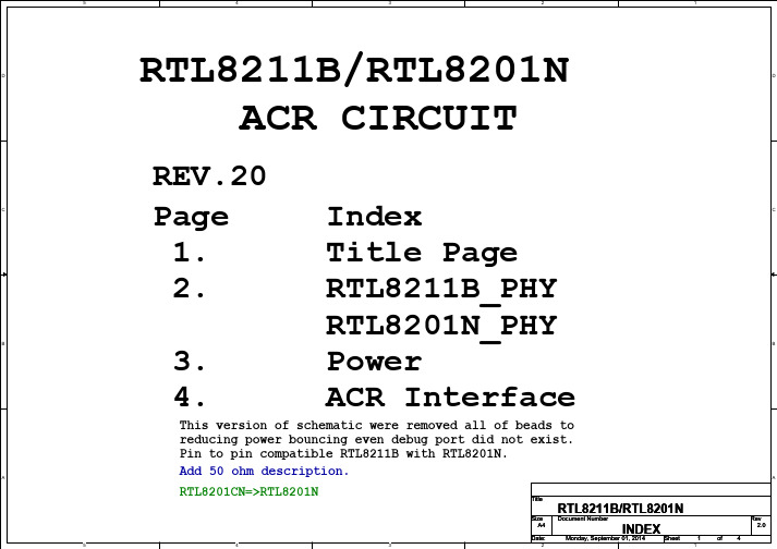
Ethernet_RTL8211B_RTL8201N_NVID
1 PHY_LINK_10 1 PHY_LINK_100 1 PHY_LINK_1000 1 PHY_FDUP 1 PHY_RX 1 PHY_TX
R2 510 R3 510 R4 R7 510 R8 510 R9 510
+ C3 GND
GND
C4
64 63 62 61 60 59 58 57 56 55 54 53 52 51 50 49
U1
GND C6 .01uF + C7 GND PHY_AVDD18 MDI0+ MDI0PHY_AVDD18 MDI1+ MDI1PHY_AVDD33 CTRL18 PHY_AVDD18 MDI2+ MDI2PHY_AVDD18 MDI3+ MDI3RX_CTL
R10
C
R11 C5
CTRL15 AVDD15 CKXTAL2 CKXTAL1 AVDD33 DVDD15 Config[0] Config[1] Config[2] DVDD33 Config[3] Config[4] RXDLY TXDLY LED_10 DVDD33
D
PHY_AVDD33
C25 .1uF
C26 .1uF
GND VDD33
C
C
CTRL18
CTRL18
Q1 2SB1188 PHY_AVDD18 C28 + C27 10uF GND C32 .1uF .1uF GND GND .1uF .1uF .1uF C29 C30 C31
RTL8201N : Q1,C27,C32 ( NC ) RTL8211B : Q1,C27,C32 ( CONNECTED )
A
A
RTL8201N : Q2,C40,C41 ( NC ) RTL8211B : Q2,C40,C41 ( CONNECTED )
北京信息科技大学校园无线网络使用指南

附件二北京信息科技大学校园无线网络使用指南北京信息科技大学无线网采用WEB认证方式,分为二次认证过程。
第一次认证是接入校园网的内网认证;第二次认证是登入internet的外网认证。
用户只有在成功进行了内网认证之后,才能进行外网认证。
用户在退出无线网络,先要退出外网,再退出内网,以免影响用户的再次登录。
如果用户没有按照这个顺序操作,用户需要等待十分钟才能成功进行登录。
一、准备网络连接打开笔记本的无线开关,单击“开始”->“控制面板”->“网络连接”,双击“无线网络连接”。
出现如下窗口双击图标,右侧出现无线网络列表双击bistu连入网络,自动获得IP地址、子网掩码、默认网关、DNS。
二、进行身份认证本使用指南在Windows XP使用Internet Explorer 8制作,其他浏览器使用方法略有差异。
打开浏览器,输入任意网址,弹出“证书错误: 导航已阻止”页面,点击“继续浏览此网站(不推荐)。
”页面自动跳转到认证页面。
输入正确的“用户名”和“密码”之后,弹出“证书错误: 导航已阻止”页面。
点击“继续浏览此网站(不推荐)。
”弹出内网退出页面。
用户在使用网络过程中,请不要关闭这个页面,以备退出内网时使用。
如果用户不慎关闭了此页面,请登录https://6.6.6.6/fs/customwebauth/logout.html,恢复这个页面。
至此,内网认证过程结束。
下面进行外网认证,如果用户只想使用校园网资源,用户不必进行外网认证。
内网认证成功之后,会弹出“外网登录”页面,输入正确的“用户名”、“密码”,点击“登录”按钮,登录外网,访问Internet。
用户输入正确的账号、密码之后,出现以下页面,请不要关闭这个页面,以备退出Internet时使用。
如果用户不慎关闭了此页面,请登录http://10.78.17.3/clogout.htm,恢复这个页面。
至此,登入外网认证完成。
三、退出无线网络用户退出无线网络时务必先退出外网,再退出内网。
USB无线网卡

相容Wireless 802.11n USB 無線網卡EW-7711UMn•迷你輕巧的外觀設計,攜帶方便•採1T1R MIMO 傳輸技術,傳輸速率高達150Mbps •採用USB 底座延長線,可任意擺放接收位置,有效加強訊號接收•獨家EZmax Setup Wizard 安裝精靈,安裝設定超容易特色EW-7711UMn USB 無線網路卡,採1T1R MIMO 傳輸技術,傳輸速率高達150Mbps ,使用EW-7711UMn ,可以讓您的筆記/桌上型電腦配備無線網路功能,可透過無線網路享受瀏覽網頁、收發E-mail 、線上聊天等網服務,而且EW-7711UMn 配備USB 底座延長線,可任意擺放接收位置,有效加強訊號接收,在家中隨處都可享規格網路標準IEEE 802.11b/g/相容IEEE 802.11n 介面1 埠USB 2.0 Type A 頻段 2.4000~2.4835GHz傳輸速率11b (20MHz): 最高11Mbps11g (20MHz): 最高54Mbps受無線網路的便利而不需因網路線而限制可上網的位置。
值得一提的是,EW-7711UMn 採用高精密的無線晶片,外觀體積足足縮小了50% ,可說是迷你又輕巧的設計。
在網路傳輸安全性方面,EW-7711UMn USB 無線網路卡支援WEP 與WPA 等無線安全加密機制確保無線網路的連線安全,維護您資料傳輸的安全。
另外,EW-7711UMn ,支援軟體WPS (Wi-Fi Protected Setup )功能,可快速完成無線加密設定,更棒的是,人性化的EW-7711UMn 快速安裝精靈軟體,11n (20MHz): 最高72Mbps(40MHz): 最高150Mbps 無線安全機制WEP , WPA, WPA2, Cisco CCX 天線精密型印刷式天線作業系統Windows 2000/XP/Vista, MAC OS 與Linux 主要功能•符合IEEE 802.11b/g 、相容IEEE 802.11n 無線網路規範•採用1T1R MIMO 無線傳輸技術,有效提升傳輸效能及訊號覆蓋範圍的是人性化的EW 7711UMn 提供獨家EZmax 快速安裝精靈軟體圖形化的使用者介面,活潑生動的說明方式,讓家中所有成員都能輕鬆搞定安裝、設定,無線上網更便利。
华虹NEC推出基于0.25 μm嵌入式Flash工艺平台的USB Inter-Chip PHY IP

华虹NEC推出基于0.25 μm嵌入式Flash工艺平台的USB
Inter-Chip PHY IP
佚名
【期刊名称】《电子与电脑》
【年(卷),期】2007(000)012
【摘要】@@ 上海华虹NEC电子宣布,该公司在0.25μm嵌入式Flash平台上推出USB Inter-Chip PHY IP (HQUSBFI001),该IP为片上芯片之间的通信提供了良好的解决方案.
【总页数】1页(P37)
【正文语种】中文
【相关文献】
1.华虹NEC与C*Core强强联手 CS320内核通过华虹NEC0.25微米标准制程验证 [J],
2.华虹NEC推出业界领先的银行卡工艺平台 [J],
3.芯原为华虹NEC 0.25微米CMOS新工艺提供半导体标准设计平台 [J],
4.SMSC为便携式消费电子应用推出首款Inter-Chip USB 2.0集线器 [J],
5.华虹NEC推出USBInter—Chip PHYIP,基于0.25-JLm嵌入式Flash工艺平台 [J],
因版权原因,仅展示原文概要,查看原文内容请购买。
- 1、下载文档前请自行甄别文档内容的完整性,平台不提供额外的编辑、内容补充、找答案等附加服务。
- 2、"仅部分预览"的文档,不可在线预览部分如存在完整性等问题,可反馈申请退款(可完整预览的文档不适用该条件!)。
- 3、如文档侵犯您的权益,请联系客服反馈,我们会尽快为您处理(人工客服工作时间:9:00-18:30)。
安全标识 警告
它提醒使用者,注意某些可能导致人体伤 亡的操作程序、作法、状况等事项。
注意
它提醒使用者可能导致仪器损坏或数据永 久损失的操作程序、作法、状况等事项。
接地地线标识。 高压危险 参阅相关文件中的警告,注意提示。
4 用户使用手册
简介
IT8211 全数控电子负载 (60V/30A/ 150W) 具有10mV,1mA的高解析度和精度,让您的测 试结果更加准确。具定电压、定电流和定电阻的工作模式,短路测试的功能,简洁的操作及显 示介面,內建4*40 组快速键设定,让您轻松并快速的完成各种复杂的测试。
短路操作 输入开启/关断键
进气口
主电源开关
面板布局
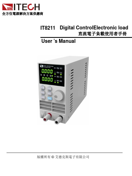
设置指示灯
电压设置指示灯 定电流模式指示灯 快捷键模式指示灯 定电压设置指示灯 短路操作指示灯 定电阻模式指示灯 量程选择指示灯 Shift指示灯 负载输入关断指示灯 电流设定指示灯 快捷键调用(shift) 右移键+ 快捷键B 量程选择(shift) 旋钮编码器 工作模式选择键+快捷键D
保固服务
本公司对本产品的材料及制造,自出货之日起,给予一年的质量保固。 本产品若需保固服务或修理,必须将产品送回本公司指定的维修单位。送回本公司作保固服 务的产品,顾客须预付寄送到本公司维修部的单程运费,本公司将负责支付回程运费。产品 若从其它国家回厂维修,则所有运费、关税及其它税赋均须由顾客负担。
极性反接保护功能 • 可预设多组输入电压及电流:4×40组 • 最简易方便的操作界面 • 开关控制 • 具可编程LIST输入模式:25×4组
CR定电阻工作模式
V
当设定为定电阻模式
CR时,ITECH电子负
载将吸取与输入电
压成线性正比例的负
载电流
I
Constant resistance
用户使用手册 5
Panel Layout
Shift键
正输入端子
负输入端子
用户使用手册 7
快速启动
Warranty
This hardware product is warranted against defects in material and workmanship for a period of ONE year from date of delivery. IT6720 power supply for use with a hardware product and when properly installed on that hardware product, are warranted not to fail to execute their programming instructions due to defects in material and workmanship for a period of 90 days from date of delivery. During the warranty period our company will either repair or replace products which prove to be defective. Our company does not warranty that the operation for the software firmware or hardware shall be uninterrupted or error free. For warranty service, with the exception of warranty options, this product must be returned to a service facility designated by our company. Customer shall prepay shipping charges by (and shall pay all duty and taxes) for products returned to our place for warranty service. Our company shall pay for return of products to Customer.
Shift button
Input +
Input -
6 用户使用手册
面板布局
电压设定/测量显示 步进值B+快捷键预设置B 步进值A+快捷键预设置A 步进值C+快捷键预设置C 步进值D+快捷键预设置D
电流设定/测量显示 快捷键储存(shift)
左移键+ 快捷键A 功能设置(shift) 显示切换+快捷键C
The ITECH product you have purchased is subject to Directive 2002/96/EC of the European Parliament and the Council of the European Union on waste electrical and electronic equipment (WEEE) and, in jurisdictions adopting that Directive, is marked as being put on the market after August 13, 2005, and should not be disposed of as unsorted municipal waste. Please utilize your local WEEE collection facilities in the disposition of this product and otherwise observe all applicable requirements.
Limitation of Warranty
The foregoing warranty shall not apply to defects resulting from improper or inadequate maintenance by the customer, customer-supplied software or interfacing, unauthorized modification or misuse, operation outside of the environmental specifications for the product, or improper site preparation and maintenance.
Switch +memory C Short on/off
Input on/off button
Air flow input
Main power on/off
Panel Layout
Setup indicator
Voltage setup indicator CC mode indicator Recall indicator CV mode indicator Short indicator CR mode indicator Shift indicator Input off indicator Current setup indicator Recall (shift) Right arrow + memory B 3/30A selector(shift) Rotary encoder Mode selector + memory D
Safety Symbols
Connect it to safety earth ground using the wire recommended in the user’s manual. High voltage danger
The symbol on an instrument indicates that the user should refer to the operating instructions located in the manual.
用户使用手册
直流电子负载 型号 1
版权归属于艾德克斯电子(南京)有限公司 Ver3.0/Jan, 2010/ IT8211
WARNING
Safety Regulations
To avoid electrical shock, do not open the cabinet. Refer servicing to qualified personnel only. To avoid injuries, always disconnect power, discharge circuits, and remove external voltage sources before touching components. KEEP AWAY FROM LIVE CIRCUITS. We cannot accept responsibility for any direct or indirect financial damage or loss of profit that might occur when using the power supply. The instrument chassis and cover must be connected to an electrical ground.
安全规则
为防止触电,非本公司授权人员,严禁拆开机器。 严禁将本设备使用于生命维持系统或其他任何有安全要求的设备上。 我们对于使用本产品时可能发生的直接或间接财务损失,不承担责任。
Certification
We certify that this product met its published specifications at time of shipment from the factory.
