分配器安装手册
负载分配器LSM672使用说明书
LSM672负载分配器使用说明书LSM672是安装在发电机控制柜内,和他其的设备在一起。
该单元安装环境要求通风冷却流畅,因为单元内部的三个负载电阻大概要消耗6.25W的电能用于发热。
警告电气连接可以参考电气连接图。
在某些特别的端子上,连接线的规格应该要满足该端子的最大电流情况。
端子7-12的最大电流可能达到5A,其他的端子电流也不少于50mA,而继电器触点端子的额定允许电流为10A。
端子N接入3相交流电的中性点,发电机是星型接法。
基本说明端子1-6是三相交流电电压输入,根据发电机的电压选择合适的三个连接端子。
选择可以参考连接图。
端子7-12连接的是来自5A电流互感器的三相电流信号。
在电流互感器额定容量许可的情况下,该电流信号可以进行串联连接,不过这可能增加工作板已经电流互感器线路的负担,同时还要注意端子8、10和12,它们都是连接电流互感器的同名端,一定要给电流互感器的同名端相匹配。
端子13、14是并联连接端子,所有同一并网系统的分配器都通过这两个端子并联起来。
它们连接时极限不能接反(所有分配器的13连在一块,14连在一块)。
如果并联线的长度超过1m,那么需要使用屏蔽线,并且把屏蔽线连接到端子23上。
继电器触点端子的连接必须要适用于低电流情况<1mA(干式触点)。
端子15是负载分配器的信号输出端,它连接发电机的速度控制单元,如果该控制线的长度超过1m,那么它也要使用屏蔽线,并且把屏蔽线连接到端子23上。
端子16是正功率复位端,使用一个常开的开关和发电机速度控制单元上的10VDC电源连接,当正功率继电器吸合后,通过点动连接开关,就可以把正功率继电器复位到正常的关闭状态。
通过端子16与电瓶的负极之间的不同连接方式,则可以通过端子16调节正功率监视器的范围。
例如在端子16与电源负极之间连接一个1MΩ的电阻,就可以把调节范围从100%是开启/40%时关闭调节成为85%开启/5%时关闭。
如果还有其他的特别调节需求,请和GAC的技术服务人员联系。
分配器 说明书

分配器用户手册目 录1、分配器-AV (1)1.1 AV-103分配器 (1)1.2 AV-108分配器 (1)2、分配器-DVI (2)2.1 DVI-1*2分配器 (2)2.2 DVI-1*4分配器 (3)3、分配器-V (4)3.1 Video-104分配器 (4)3.2 Video-1*16分配器 (4)4、分配器-VGA (5)4.1 VGA-0102分配器 (5)4.2 VGA-104分配器 (6)4.3 VGA-1*8分配器 (7)4.4 VGA0116分配器 (8)4.5 VGA-1*10/24分配器 (9)1 分配器-AV1.1 AV-103分配器AV-1*3分配器主要用以解决在多媒体投影工程中,将一路高分辨率音视频信号分配成三路高分辨率音视频信号。
AV-103后背板技术性能及指标:输入接口: 1路 BNC(VIDEO),1路RCA输出接口: OUTPUT1―3BNC; OUTPUT2―3 RCA阻 抗: 输入阻抗:75Ω输出阻抗:75Ω电 源: 220V /AC外形尺寸: 45×25×15mm(D×W×H)重 量: 0.3Kg配 件: 使用说明书1.2 AV-108分配器AV-1*8分配器主要用以解决在多媒体投影工程中,将一路高分辨率音视频信号分配成八路高分辨率音视频信号。
AV-108后背板技术性能及指标 :输入接口: 视频: 1路 BNC(VIDEO),音频:1路音频头(凤凰端子)输出接口: 视频:OUTPUT1―8BNC;音频:OUTPUT1―8 音频头(凤凰端子)阻 抗: 输入阻抗:75Ω输出阻抗: 75Ω电 源: 220V 50HZ的交流电源外形尺寸: 235×155×70mm(D×W×H)重 量: 1.3Kg配 件: 使用说明书2 分配器-DVI2.1 DVI-1*2分配器在许多多媒体应用系统中,往往需要把一个DVI信号源输送到中心机房进行处理,同时又需要在本地显示该信号。
最新分配器说明书上海金灿12资料

随机资料,使用前请务必仔细阅读!分配器/延长器/线控说明书精品文档目录前言 (2)一、分配器的使用说明 (3)1、分配器功能 (3)2、分配器分类 (3)3、装箱清单 (4)4、系统连接图 (6)5、输入、输出接口 (4)6、技术指标 (5)二、延长器的使用说明 (7)1、信号延长器简介 (7)2、信号延长器指标及连接图 (7)三、线控的使用说明 (16)1、线控简介 (16)2、线控接口 (16)3、技术指标 (17)4、连接图 (18)常见故障及维护 (19)精品文档前言感谢您使用本公司产品,使用时请注意以下事项:1.本产品所使用电源必须有电源保护地线,输入、输出设备的电源保护地线要为同一保护地线。
确保设备的输入电源为AC 100~240V/50Hz。
2.使用计算机控制本产品时必须保证控制计算机与本产品的连接电源保护地线是同一个地线。
3.使用本产品时严禁带电插拔输入、输出信号线及RS232通讯接口线。
4.严禁将本产品放在过热或过冷的地方工作,应保持工作环境通风良好。
严禁将化学物品洒在本产品上。
5.严禁对本产品的机械和电路设计进行更改或增减任何部件,否则厂家对此产生的任何结果不负责任。
6.严禁擅自打开机箱外壳,机器内有交流220V高压,以免发生触电危险,需要维修时应交厂家进行维修。
精品文档一、分配器的使用说明1、分配器功能分配器的功能是将一路输入信号源均等的分成多路输出,并且输出信号与输入信号完全相同、有些型号甚至还带有图像增益放大输出功能;输出信号与输入信号相比不会有衰减、延迟等不良的现象。
2、分配器分类根据输入信号的不同,有:纯视频分配器视音频分配器VGA分配器VGA+音频分配器RGB分配器网线分配器DVI分配器HDMI分配器等根据分配的端口数而分,有:0102 1进2出0104 1进4出0108 1进8出精品文档精品文档0116 1进16出 0132 1进32出 0164 1进64出等3、装箱清单4、输入、输出接口VGA: D-Sub15Pin (对含有VGA 的分配器)。
有线电视放大器分配器安装方法

有线电视放大器、分频器作用及安装方法一、有线电视信号要求:1:信号强度用户信号电平:60-80dBμV信号电平低于60dBμV时,电视屏幕出现雪花点或杂乱的干扰条纹,信号电平高于80dBμV时,电视屏幕出现扭曲或浮雕状画面.2:信号质量载噪比:≥43dB载噪比达不到要求,即使用户信号电平合适,电视屏幕出现的也只是一幅充满雪花点的干扰图像。
载波互调比:≥54 dB载波互调比达不到要求时,表现为电视画面上产生斜网状干扰。
交扰调制比:≥46 dB交扰调制比达不到要求时,表现为图像上产生垂直白条或两个图像同时出现在屏幕上的串像现象。
注:信号质象在传输中不断下降,任何一个部件的接入都会降低信号质量。
二、有线电视信号放大器的主要作用:1. 电视信号强度不够时,增强信号电平,减少屏幕雪花点。
2. 多台电视机同时使用时,补偿分支分配器的信号损耗,保证信号强度。
3. 远距离收看电视时,补偿电缆传输的信号损耗。
(标准75-5 电缆750MHz/100 米的损耗约18 dB.)三、使用效果欠佳原因分析:1.使用效果不明显。
当信号电平强度达到规定要求,信号质量(载噪比,载波互调比,交扰调制比)的某项指标达不到规定的要求,造成电视画面出现不清晰的图像时,装上电视信号放大器对信号进行放大,此时信号强度增强,但信号质量没有改变,由于信号强度在放大前已经达到规定要求,所以电视画面依然出现不清晰图像,使用效果不明显。
2.使用后图像反而变差。
当信号电平强度较强时(75-80 dB μV),信号质量的某项指标达不到规定的要求,造成电视画面出现不清晰图像时,装上电视信号放大器对信号进行放大,较强的信号放大后,输出的信号电平超出放大器自身最大的输出电平,放大器工作于非线性区,非线性失真使系统中产生大量的谐波对图像造成严重的干扰,即载波互调比及交扰调制比严重下降,所以图像反而变差。
3.使用后图像好差颠倒。
当信号电平不同频段内偏差较大时(通常V段电平较强,U段电平偏低),信号质量基本满足规定要求,收看时部分频道清晰,部分频道雪花干扰。
西门子无缝负载分发器安装说明书

sA0190This confirmation does not imply any guarantee of quality or durability. The safety instructions of the accompanying product documentation shall be observed.Diese Bestätigung enthält keine Beschaffenheits- oder Haltbarkeitsgarantie. Die Sicherheitshinweise der mitgelieferten Produktdokumentation sind zu beachten.Siemens Aktiengesellschaft: Chairman of the Supervisory Board: Gerhard Cromme; Managing Board: Joe Kaeser, Chairman, President and Chief Executive Officer;ConfirmationBestätigungProduct identification:ProduktbezeichnungFuseless load feeder, Sicherungslose Verbraucherabzweige 3VA2.. + 3RW405..3VA2.. + 3RW407..3VA2.. + 3RW443..3VA2.. + 3RW444..Manufacturer:Siemens AG, DF CP Hersteller Address:DE-92220 AmbergAnschriftFuseless load feeder / coordination type 1according IEC 60947-4-2 at AC 400 VSicherungslose Verbraucherabzweige / Zuordnungsart 1 nach IEC 60947-4-2 bei AC 400 VWe confirm that the fuseless load feeders, mentioned above consisting of circuit breakers 3VA2.. and soft starter 3RW4.. corresponding to attached annex and in compliance with the installation guidelines fulfill the conditions for the coordination type 1 mentioned in the enclosures according to IEC 60947-4-2, Edition 3.0 (05-2011).Hiermit bestätigen wir, dass oben genannte sicherungslose Verbraucherabzweige, bestehend aus Leistungsschalter 3VA2.. und Sanftstarter 3RW4.. wie in den beigefügten Tabellen aufgelistet und unter Einhaltung der entsprechenden Aufbaurichtlinien die Anforderung der Zuordnungsart 1 nach IEC 60947-4-2, Edition 3.0 (05-2011) erfüllen.Siemens Aktiengesellschaft DF CP R&D 92220 Amberg2016-06-30 ___________ Ambergdate of issueplaceProduct description Confirmation No.: A0190 Type designation:3VA2.. + 3RW405..3VA2.. + 3RW407..3VA2.. + 3RW443..3VA2.. + 3RW444..Manufacturer:Siemens AG, Low VoltageSiemensstraße 10, 93055 RegensburgSiemens AG, GWAWerner-von-Siemens-Str. 48, 92220 AmbergProduction site:OEZ s.r.o.Sedivska 339, 561 51 LETOHRADCZECH REPUBLICSiemens AG, GWAWerner-von-Siemens-Str. 48, 92220 AmbergOverview series 3VA..3VA2450 -5MN 32-..I II III IV V VI VII VIIII.Basic type3VA2 -SENTRON nG Circuit Breaker for selective applications II.Frame size2 -Up to 200 A3 -Up to 250 A4 -Up to 500 AIII.Rated current16 -160 A20 -200 A25 -250 A32 -320 A40 -400 A50 -500 AIV.AIC-level5 -Class M6 -Class H7 -Class CV.Trip unit: Characteristic curve, typeMN -ETU350M LSI Motor protectionMQ -ETU860M LSIG Motor protection + display and metering function VI.Poles3 -3PolesVII.Connection technology1 -Without all (without any terminals)2 -Screw terminals at front side3 -Front connection at line side / Rear connection at load side4 -Rear connection at line side / Front connection at load side5 -Screw terminals at rear side6 -Front side cable connection7 -Without all (without any terminals) at line side / Front side cable connectionat load sideVIII. Others.. -Manufacturer’s identificationOverview series 3RW40..3RW4036 -1 B B 14I II III IV V VI VII VIII I -Basic type3RW4 – AC semiconductor motor starterII -Kind of device0Soft starterIII - Rated operational power Pe at 400VRated operational current I eAC-53a at 400VPe: Ie:55 75 kW132 A56 90 kW160 A73132 kW230 A74160 kW280 A75200 kW350 A76250 kW432 AIV - Type of Terminals2Main contacts: Busbar connectionsAuxiliary contacts: Spring typ terminal6Main contacts: Busbar connectionsAuxiliary contacts: Screw terminalV - Special functionB with bypassVI - Phases controlledB- two-phase controlledVII - Rated control supply voltage, Us3- 115 V AC4- 230 V ACVIII - Rated operational voltage, Ue4 - 200 up to 460 V AC5 - 400 up to 600 V ACOverview series 3RW44..3RW4 4 22- 6B C 4 4I II III IV V VI VII VIII I -Basic type3RW4 - AC semiconductor motor starterII -Kind of device4Soft starter “High Feature”III - Rated operational power Pe at 400VRated operational current I eAC-53a at 400VPe: Ie:34 55 kW113 A35 75 kW134 A36 90 kW162 A43110 kW203 A44132 kW250 A45160 kW313 A46200 kW356 A47250 kW432 AIV - Type of Terminals2Main contacts: Busbar connectionsAuxiliary contacts: Spring typ terminal6Main contacts: Busbar connectionsAuxiliary contacts: Screw terminalV - Special functionB with bypassVI - Phases controlledC three phase controlledVII - Rated control supply voltage, Us3115 V AC4230 V ACVIII - Rated operational voltage, Ue4200 up to 460 V AC5400 up to 600 V AC6400 up to 690 V ACTable: load feedersTest: IEC 60947-4-2, 9.3.4 Performance under short-circuit conditionsThe tables below show all possible combinations.Every type of terminals of the soft starter is possible.Every control supply voltage of the soft starter is possible.For the connection of circuit breaker and soft starter only cables can be used.Listed soft starters cover soft starters of the same size and same short circuit rating, but higher rated current.3RW40.., Class 10:U e = 400 V, Coordination type 1IeAC53a [A]Circuit breaker Soft starterSetting range[A]Iq[kA]1343VA2216-5MN323RW405563 - 16055 1403VA2216-5MN323RW405663 - 16055 1623VA2220-5MN323RW405680 - 20055 1753VA2220-5MN323RW407380 - 200100 2303VA2325-7MN323RW4073100 - 250100 2503VA2325-7MN323RW4074100 - 250110 2803VA2440-7MN323RW4074160 - 400110 3503VA2440-7MN323RW4075160 - 400110 3563VA2450-7MN323RW4075200 - 500110 4323VA2450-7MN323RW4076200 - 5001103RW44.., Class 10:U e = 400 V, Coordination type 1IeAC53a [A]Circuit breaker Soft starterSetting range[A]Iq[kA]1133VA2216-5MN323RW443463 - 16055 1343VA2216-5MN323RW443563 - 16055 1403VA2216-5MN323RW443663 - 16055 1623VA2220-7MN323RW443680 - 20055 1753VA2220-7MN323RW444380 - 200110 2033VA2325-7MN323RW4443100 - 250110 2503VA2325-7MN323RW4444100 - 250110 3133VA2440-7MN323RW4445160 - 400110 3563VA2450-7MN323RW4446200 - 500110 4323VA2450-7MN323RW4447200 - 500110。
电视机顶盒分配器安装方法
电视机顶盒分配器安装方法导语:电视机顶盒分配器可以破解电视机顶盒,并且能够连接到多台电视机。
电视机顶盒分配器是很简单又比较复杂的一种机器,安装简单,一线进多线出。
结构复杂,因为要破解很多的东西。
一个盒子也可以链接到多个电视,但是那样做电视机就都是放的同一个电视节目,这时候我们就要用到电视机顶盒分配器。
电视机顶盒分配器是什么电视机顶盒分配器就是把有线电视的信号改变数字加密之后,通过算法加密向外输出。
电视机顶盒分配器就是破解的电视信号加密内容,然后得到了非配。
这里面有些解密的方法,比如加扰法。
对传输流的一个加扰,这是在欧洲有一个DVB标准的。
还有是对控制字的加密算法,采用RSA和3DES算法,不同的厂家各有技术上的不同,但是效果都是一样的。
电视机顶盒分配器安装方法【1】电视机顶盒分配器能够分出来电视机信号,让两台电视机都能够正常的观看到电视节目,而且还是互不干扰的。
这是一种电视机顶盒分配器的安装方法:1.电视机顶盒分配器的替换,用专业的电视机顶盒分配器代替家中原有的电视机顶盒分配器。
2.打开两台电视机观看电视节目,这样做的目的是确认专用分配器安装正确与否。
3.电视机顶盒分配器是安装在家中的弱电箱中的,可以去看看自己家中的弱电箱里面有没有安装。
4.有家用信号放大器的用户,将信号放大之后在输入端链接上电视机顶盒分配器,这样做就能够分别的向两台电视传输到电视信号。
5.室内未采用分配器而直接采用串联用户盒连接的,将串联用户盒连接改为专用分配器连接。
电视机顶盒分配器安装方法【2】电视机顶盒分配器安装方法比较多一点,不同品牌的厂家生产的电视机顶盒分配器都有不同的安装方法,上面的使用说明也会看到相关的安装方法。
这是另一种安装电视机顶盒分配器的方法:1.将原有的电视机顶盒进行拆卸;2.然后按照F线头进行线头的制作;3.光纤先的芯和网固定在红外接收器的输入端上,要注意在链接的时候避免芯和网发生短路。
4.红外接收头粘贴在电视机的正面边角上,通过用户线把红外接收器的射频输出口和电视机的射频输入口连接起来。
HDMI分配器一分四参数和使用手册

用户手册1x4 HDMI 分配器使用手册享受高清影像世界!尊敬的客户:您好!非常感谢您购买本公司的产品。
为了实现产品的最佳效果和保证安全,请您在对产品进行连接、操作、调试前仔细阅读本手册。
此手册请予以保留,以备将来查阅。
本公司所生产的HDMI转换器、切换器、网线延长器、矩阵、分配器等系列产品,其设计之目的是为了让您的影音设备使用起来更便捷,更舒适,更高效,更节能。
这款1 x4 HDMI分配器可以把一个高清信号源连接到四个高清显示终端。
它可以很容易地将一个高清信号源所产生的高清信号分配到四台支持高清信号的显示器或者投影机上。
另外,把它接在一根HDMI线的信号输出端时,可对HDMI信号进行放大。
本公司所生产设备为以下应用提供解决方案:如对噪声、传输距离及安全有限制的场所、数据中心控制、信息分配、会议室演示以及教学环境和公司培训场所。
真诚服务是我们的理念,顾客满意是我们的宗旨。
本公司将以最优惠的价格提供给客户最好的产品,并竭诚为客户提供优质服务。
产品特点:●一路HDMI1.3b版本信号输入分配成四路HDMI1.3b版本信号输出●兼容HDCP1.2●支持3D●支持CEC●支持30/36位深色●支持蓝光DVD24/50/60fs/HD-DVD/xvYCC●音频格式DTS-HD/Dolby-trueHD/LPCM7.1/DTS/DOLBY-AC3/DSD●支持信号时序重整。
●使用AWG26 HDMI 1.3版本的标准线缆,输入传输距离可达15米,输出传输距离可达25米。
●无信号损失●安装简单●需要DC5V/1A规格的电源随机配送附件图示:1、5V电压电源适配器2、说明书一份电源适配器物理连接口示意图:图1.0 前面板示意图:电源开关POWER :电源指示灯Input:HDMI输入指示灯Output1- Output4:HDMI输出指示灯图1.1 后面板示意图Ooutput1- Ooutput4: HDMI输出接口Input: HDMI输入接口DC/5V:5V直流电源接口连接与操作:1.通过一条HDMI线缆,把高清信号源和分配器的输入口连接起来。
5069 Compact I O 现场电源分配器安装说明书
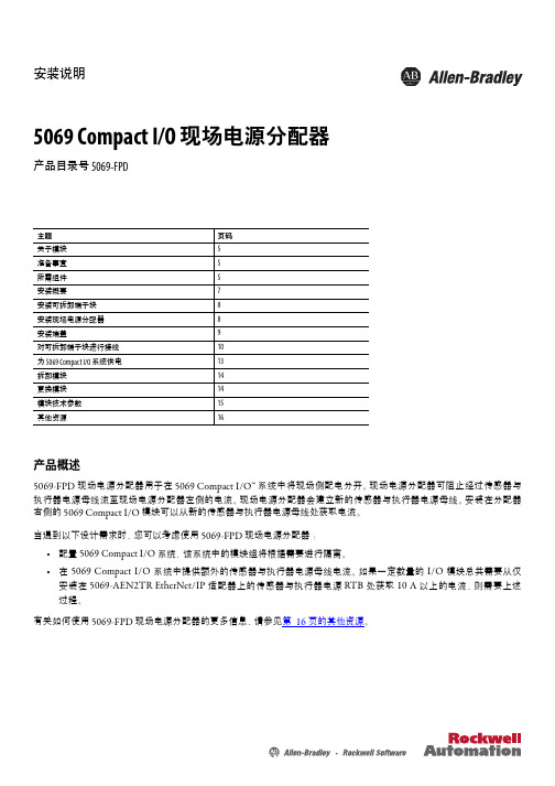
安装说明5069 Compact I/O 现场电源分配器产品目录号 5069-FPD主题页码关于模块5准备事宜5所需组件5安装概要7安装可拆卸端子块8安装现场电源分配器8安装端盖9对可拆卸端子块进行接线10为 5069 Compact I/O 系统供电13拆卸模块14更换模块14模块技术参数15其他资源16产品概述5069-FPD 现场电源分配器用于在 5069 Compact I/O™ 系统中将现场侧配电分开。
现场电源分配器可阻止经过传感器与执行器电源母线流至现场电源分配器左侧的电流。
现场电源分配器会建立新的传感器与执行器电源母线。
安装在分配器右侧的 5069 Compact I/O 模块可以从新的传感器与执行器电源母线处获取电流。
当遇到以下设计需求时,您可以考虑使用 5069-FPD 现场电源分配器:•配置 5069 Compact I/O 系统,该系统中的模块组将根据需要进行隔离。
•在 5069 Compact I/O 系统中提供额外的传感器与执行器电源母线电流。
如果一定数量的 I/O 模块总共需要从仅安装在 5069-AEN2TR EtherNet/IP 适配器上的传感器与执行器电源 RTB 处获取 10 A 以上的电流,则需要上述过程。
有关如何使用 5069-FPD 现场电源分配器的更多信息,请参见第16 页的其他资源。
2罗克韦尔自动化出版物 5069-IN001B-ZH-P - 2015年10 月5069 Compact I/O现场电源分配器Read this document and the documents listed in the Additional Resources section about installation, configuration and operation of this equipment before you install, configure, operate or maintain this product. 注意:在安装、配置、操作和维护本产品前,请阅读本文档以及“其他资源”部分列出的有关设备安装、配置和操作的相应文档。
洗碗机分配器使用说明书
洗碗机分配器使用说明书一、简价洗碗机分配器,适用于国外销售的任何品牌洗碗机。
是一种准确方便经济实用的洗碗机清洁剂、催干剂分配器,有门式、通道式专用型,有探头和时间速度双模式控制方法,有CPU控制的探头、非探头(时间、速度)双模式控制,适用于任何类型洗碗机上使用。
二、安装1、分配器安装在洗碗机的进口上方墙体,打两个φ6塑胶膨胀管螺丝固定分配器,须将密封垫片安在墙头,防蒸发进入箱体内。
2、管路安装1)将φ6塑管截成适当长度,插入泵管两端用扎带扎紧,注意不要将吸入口、出口搞反。
泵的转向应是顺时针方向,吸入口的塑管末端装上过滤底阀,长度能放入清洁剂和催干剂的桶内,出口与清洁剂下药口和单向阀连接。
2)清苦剂进口,在洗碗机洗涤槽水平面上方,打一个φ10.2-10.5孔或7/8”标准孔装上进药口装置.3)催干剂进口须单向阀,一般洗碗机上有预留口。
3、探头安装必须安装在洗涤槽的水平面下10CM左右的地方,最好的位置应离水泵吸口较近,离进水口较远,切忌安装在加热管附近,否则容易熔化,选择好位置后打一个22(7/8英寸)的孔,用0.75-1平方米多股软线,连接至分配器的探头信号连接柱上.4、电路安装1)分配器工作电压(常电源)220V、110V,如有24V电压则不必接变压器电源,电源单独设置电源开关(以备清洗洗碗机用)。
2)连接主电源前检查洗碗机输出端电压再进行连接,以免烧坏变压器及电路板,确实后再连接。
3)一般洗碗机都在电控箱内,留有洗涤剂催干剂的电源信号接口,比较方便的就可接在分配器的触发信号连接柱上,电压范围在14V-230V都可以。
4)若洗碗机没有预留洗涤干剂的电源信号,可以将触发电源信号连接在主洗接触器和过水接触器的电源上。
5)分配器选择在时间速度控制模式时,则将首次加药的电源信号,连接进水电磁阀的电源上。
6)远程预警,可用连接线将分配器内ALARM 连接柱连接外部报警器(3V-24V)。
5、设置与调试1)具体见电路板图示和屏幕显示及设置。
MW-1000洗衣房分配器操作手册说明书

用户手册MW-1000 洗衣房分配器(本页留白)1.OO 概览页数1.01 包装清单4 1.02 操作4 1.03 型号及参数4 1.04 规格概览52.OO 安装2.01 现场勘测及安装要求6 2.02 主机安装6 2.03 水源和气源连接7 2.04 吸料管连接7 2.05 出料管连接8 2.06 编程8 2.07 电源连接93.OO 维护3.01 预先准备11 3.02 PC板的维护11 3.03 气动隔膜泵维护12 3.04 电磁阀的维护124.OO 检修4.01 检修135.OO 更换部件5.01 爆炸图14 5.02 配件料号146.OO 质保6.01 有限质保151.O1 包装含有1) MW-1000 分配器4) 钥匙 (在安装配件包里)2) 操作说明书 (P/N HYD10099156)5) 信号盒组件 (P/N HYD10-03609-00)*3) 安装配件包6) TE 控制器组件 (P/N HYD01-08900-11)**数量由订购的分配器型号决定安全防范警告! 请仔细阅读本警告并遵守当地规章制度感谢购买我们的产品请正规操作以免工伤和其他伤害:当分配器清洁剂、更换料桶、清洁设备时,请穿防护衣,戴安全眼镜阅读并遵守清洁剂厂商提供的SDS安全条例按照清洁剂供应商提供的指示稀释或分配清洁剂 灌装清洁剂时不要对准自己和他人 时常检查设备以确保设备保持清洁,得以正常维护 安排合格的技术员安装操作设备,尤其要有电工上岗证当安装、维护分配器时;当分配器的控制箱被打开的时,务必确保电源已关闭 切勿混合不相容的清洁剂以免引起爆炸穿戴一直切勿1.O2 操作MW-1000 分配器是一款设计紧凑,经济实惠的产品。
最多可配合8台水洗机,最多分配8种清洁剂。
适用于各类洗衣工厂和酒店洗衣房。
通过海卓经典的信号盒和TE控制器与洗衣机连接。
注意! MW-1000 分配器旨在减少安装时间、安装配件和维护时间。
洗碗机分配器使用说明书

洗碗机分配器分配器的安装1、机身安装将机身固定在架子或垂直的墙面上,保证机身远离洗碗机的通风口及蒸汽通道上,否则会造成设备过热,从而影响运行状况。
机身后壳上的预留孔是用于安装于墙面时上螺丝之用,安装时需加密封垫片。
2、分配器安装1)探头的安装:当分配器选择探头控制加料模式时,必须安装探头。
探头必须安装在水箱液面以下,并尽可能的在靠近水箱底部的洗碗机缸臂上钻一个的孔,用橡胶圈从内、外部固定探头。
探头应与热源、洗涤剂入口、排水管、进水管等保持一定距离。
2)洗涤剂注入器的安装注入器应安装在水箱液面以上,在洗涤缸臂适当位置钻一个的孔安装注入器,作为洗涤剂的入口。
用橡胶垫圈从内部固定注入器。
3)催干剂单向阀的安装将单向阀安装在洗碗机的过水管或者加热包上。
一般洗碗机上有预留接口;若没有,在管壁厚度足够的情况下,自钻一个11/32()的孔或用三通来替代。
4)输液管连接将ф6MM的白色输液管插入洗涤泵的黑色蠕动胶管末端,并用拉带扎紧。
再将输液管截成适当长度的两段,长度以达到洗涤剂料桶与重锤注入器连接。
进料输液管末端与注入器用白色螺帽紧密连接。
同样,将ф6MM的输液管截成适当长度的两段,长度以达到催干剂料桶与重锤连接。
进料输液管一端与催干泵的黑色蠕动胶管末端相连,另一端与白色PVC吸液管用白色螺帽相连,然后一并放入催干剂料桶。
出料输液管末端与单向阀相连。
电路安装1、分配器工作电压(常电源)220V、110V,如果有24V电压则不需要安装变压器电源,电源单独设置电源开关。
2、连接主电源前检查洗碗机输出端电压后再进行连接,以免烧坏变压器以及电路板。
3、一般洗碗机都在电控箱内,留有洗涤剂催干剂的电源信号接口,比较方便的就可以接在分配器的触发信号连接柱上,电压范围在24V—230V都可以。
4、如果洗碗机没有预留洗涤剂催干剂的电源信号,可以将触发电源信号连接在主洗接触器和过水接触器的电源上。
5、分配器选择在时间速度控制模式时,则将首次加药的电源信号,连接进水电磁阀的电源上。
分液器cp619说明书

分液器cp619说明书数字流体分配器使用说明书数字型分配器使用说明书一.简介CP619分配器是一种方便轻巧的装置,可以准确,适量的向商用洗碗机注入洗涤剂,催干剂等化学药剂。
采用专业设计的洗涤电路板,可实现探头或时间双模式控制加料。
分配器面板上还设有洗涤▲及催干▼手动加药按钮,可适用于各类门式和通道式洗碗机。
二.分配器的安装1.机身安装将机身固定在架子或垂直的墙面上,保证机身远离洗碗机的通风口及蒸汽通道上,否则会造成设备过热,从而影响运行状况。
机身后壳上的预留孔是用于安装于墙面时上螺丝之用。
2. 分配器安装1)探头的安装:当分配器选择探头控制加料模式时,必须安装探头。
在距离水位线10CM处,通常距水箱底部30-50mm处的洗碗机缸壁上钻一个22.5MM的孔, 用橡胶垫圈从内部固定探头。
探头应与热源,洗涤剂入口,排水管,进水管等保持距离。
2)洗涤剂注入器的安装注入器应安装在探头之上。
在洗涤缸溢流线的上方钻一个22.5MM的孔安装注入器,作为洗涤剂的入口。
用橡胶垫圈从内部固定注入器。
3)催干剂单向阀安装将单向阀安装在1/8“NPT的洗碗机的过水管线上。
一般洗碗机上有预留接口。
若没有,在管壁厚度足够的情况下,自钻一个11/32“(8.7MM)的孔或用鞍型夹代之。
4)输送管连接将φ6MM的输送管插入洗涤泵的黑色蠕动胶管末段,并用拉带扎紧。
再将输送管截成适当长度的两段,长度以达到洗涤剂料桶和注入器为准。
进料输送管末端与灰色PVC吸液管用白色螺帽相连,然后一并放入洗涤剂料桶。
出料输送管末端与注入器用白色螺帽紧密连接。
同样,将φ6MM输送管截成适当长度的两段,长度以达到催干剂桶和单向阀为准。
进料输送管一端与催干泵的黑色蠕动胶管末段相连,另一端与灰色PVC吸液管用白色螺帽相连,然后一并放入催干剂料桶。
出料输送管末端与单向阀连接。
三.电路连接1、电源线(常有电)接线方法①、分配器的工作压力为240VAC、208VAC、120VAC,如有24VAC电压可直接接到电板上,当电压为220VAC时可接240VAC或208VAC。
PX128 PX136 PX128B 专业多层电源分配器用户手册说明书

PRECAUTIONSThank you for purchasing our products. Please read this manual carefully for your correct operation of this equipment, and keep this manual for future reference.For your safety please don't open the rack to avoid electric shock due to high voltage inside. Consult professionals for maintenance help.Keep the equipment off rain or humidity.This equipment must work in places with good air flow.Please check whether local voltage supply can meet the requirement of this equipment.Please pull out the plug when this equipment is not in use for a long time.Load must be configured following this manual. Don't let the equipment work overloaded for a long time.Please make sure the local power supply is similar to what this appliancerequires ( ),and carefully check there is no any damage for 220V-240V ~ 50/60Hzoutlet and wire prior to operating the appliance.279101034568CONTENTSIntroductionInstallationAdditionalInstructionFeaturesFront panel function instructions Back panel function instructionsNetwork connection FAQSafety Regulations Specifications Maintenance4Power cord connection4Please read this manual carefully before you begin to use this equipment, and keep the manual for future reference.FEATURESIt's a professional sequence power distributor, which can distribute mainpower into eight power outputs, and turn on/off every output power sequently, that to effectively reduce the shock to system, specially cater for large sound Reinforcement venue.One main power input, six or eight controlled power outputBuilt-in processor, turn on clockwise, turn off anti-clockwise, available for network connection, easy operation.LED indication for each channel turn on/offBYPASS switch and independent switch control for every channel, flexible usageCute and solid shapeINTRODUCTIONPOWER CORD CONNECTIONRed sleeved cable L N GCAUTIONRISK OF ELECTRIC SHOCKDO NOT OPEN220-240V50-60Hz Yellow sleeved cable Green sleeved cable5POWERLINKBYPASS ALL OFFCH 1CH 2CH 3CH 4CH 5CH 6CH 7CH 8PROFESSIONAL SEQUENCE POWERP X 128ONE TOUCH ONMAIN VOLTAGE ※ Take PX128 as example ( PX136 is same as PX128, except for Channel 7 and Channel 8)1: Sequent turn on/off LEDThe LED is active, when sequent switch is on.2: Sequent switch controlPress switch, every power channel is connected sequently3: Network connection LEDThe LED is active, when many systems are connected at the same time.4: Main power/voltage screen Show main power/voltage5: BYPASS switch LEDPress Bypass switch, Bypass function is activated, and LED is active6: Main power switch LED Press main power switch, cut off all channels, the LED is active7:CH1----SwitchPress the switch can cut off power of this channel independently.8:CH2----SwitchPress the switch can cut off power of this channel independently.9:CH3----SwitchPress the switch can cut off power of this channel independently.10:CH4----SwitchPress the switch can cut off power of this channel independently.11:CH5----SwitchPress the switch can cut off power of this channel independently.12:CH6----SwitchPress the switch can cut off power of this channel independently.13:CH7----SwitchPress the switch can cut off power of this channel independently.14:CH8----SwitchPress the switch can cut off power of this channel independently.15: BYPASS switchPress this switch, the function of sequent turn on/off is not available, meanwhile switch on all power channels.FRONT PANEL16: Main turn on/off switchPress this switch, cut off all channels6※ Take PX128 as example ( PX136 is the same as PX128, except for Channel 7 and Channel 8and the remote control terminals.)BACK PANELINPUT OUTPUTLINK CONTROL220-240V50-60Hz REMOTEE N L E E E E E E ECH 8N L CH 7N L CH 6N L CH 5N L CH 4N L CH 3N L CH 2N LCH 11.Power in(Please note if your local voltage is conformed to this instrument )2.Parallel connection output socket (When link, signal output from here)3.Parallel connection input socket (When link, signal input from here)4.CH1-CH8 power distribution socket5.remote control terminals(It can control the sequencer remotely with switch when short-circuiting this terminal.)7EN L CH 8INPUT OUTPUT LINK CONTROLEN L CH 8INPUT OUTPUT LINK CONTROLEN LCH 8INPUT OUTPUTLINK CONTROLINSTRUCTION OF PARALLEL CONNECTION CONTROL1>Il lustration of Parallel connection2>Remark:Please turn off all the s when link parallel. After connection, can use the first equipment to control all the s .equence power distributor equence power distributor INSTALLATIONSequence power distributor 2( auxiliary)Sequence power distributor 3( auxiliary )Sequence power distributor 1( main )2>Connection diagram of remote control terminal:INPUT OUTPUTLINK CONTROLREMOTEEN LCH 1Remote switch1122218USUAL FAILURE AND EXCEPTION HANDLESFailure Phenomena No.Exception HandlesPower indicated LED doesn't lightCannot be connected parallelOthersCheck if the plug connect well with the power supplyequipment Check if the power supply have the right voltage Make sure to connect the link control line before power onCheck if the link connection is right and well Please check the settings and linking by instructionequipment Please consult with your local specialist or browse our website: Please consult professional personnel for help if the aboven-mentionedoperation does not work efficiently.9DO NOT OPEN THE COVER :Do not open the cover to avoid the risk of electric shock caused by high voltage parts in the product. Any problems caused by user's wrong actions are out of warranty.AVOID OBJECT AND LIQUID ENTRY :T ake care that objects do not fall into and that liquids are not spilled into the inside of the product . If the object or liquid enter the product , please ask qualified personnel to check it.Please hold the plug when pull out or plug Do not pull out or touch the cord with wet hand, or it will cause the risk of electric shock. Power supply cords should be routed so they are not likely to be walked upon or pinched by items placed on or against them. When removing the cord from a power outlet be sure to remove it by holding the plug attachment and not by in the cord. pulling on the cord.DO NOT DAMAGE THE POWER CORD :SAFETY INSTRUCTIONSABNORMAL STATUS :In the event of abnormal noise and smell, please put off the power supply and pull out the cord, please ask qualified personnel to check it.NONUSE FOR A LONG TIME :When nonuse it for a long time, please put off the power supply and pull out the cord to avoid the unexpected dangers.※1016KW 2KW 1s 220V-240V~50/60Hz 5Kg 6Kg 484×222×44.5 mm 555×310×78mm One: : : : : : : : : : : PX128SPECIFICATIONTotal Max. Output (RMS)Per Channel Max. Output (RMS)Sequence Delay Time Parallel Connection Bypass FunctionVoltage N.W.G.W.Dimension (WxHxD)Packing ()WxHxD User Manual Parameters Subject To Change Without NoticeMAINTENANCEThe equipment can be cleaned with dry cotton cloth. If the equipment is abnormally dirty, please clean it with a piece of cotton cloth dipped in detergent for 5 to 6 seconds, and finally dry it with a piece of dry cloth.Don't use alcohol, insecticide, or any other volatile or corrosive liquid to clean the equipment, which will cause colour fade or flake-off of the equipment surface. When the equipment is not used for a long time, please keep it in an appropriate dry place.available available16KW2KW 1s220V-240V~50/60Hz 5Kg6Kg484×222×44.5 mm 555×310×78mm One PX128B available available18KW 3KW 1s220V-240V~50/60Hz5Kg 6Kg484×222×44.5 mm 555×310×78mm OnePX136availableavailable。
分配器说明书

洗碗机双液体电脑分配器安装使用说明书A600201-1CA600201-2C上海昌剑酒店设备用品有限公司SHANGHAI CHANG JIAN HOTEL EQUIPMENT CO., LTD.洗碗机分配器使用说明书一、简介昌剑公司最新研制开发的洗碗机分配器,适用于国内外销售的任何品牌洗碗机。
是一种准确方便经济实用的洗碗机清洁剂、催干剂分配器,有门式、通道式专用型,有探头和时间速度双模式控制方法,有CPU控制的探头、非探头(时间、速度)双模式控制,有遥控型、非遥控型。
适用于任何类型洗碗机上使用。
二、安装1. 分配器安装在洗碗机的进口上方墙体,打两个 6 墙洞,用塑料膨胀管螺丝固定分配器,须将密封垫片安在墙体上,防蒸汽进入箱体内。
2. 管路安装1)将 6塑管截成适当长度,插入泵管两端用扎带扎紧,注意不要将吸入口、出口搞反。
泵的转向应是顺时针方向,吸入口的塑管末端装上吸液管,长度能放入清洁剂和催干剂的桶内,出口与清洁剂下药口和单向阀连接。
2)清洁剂进口,在洗碗机洗涤槽水平面上方,打一个 22或7/8"标准孔装上进药口装置。
3)催干剂进口须装单向阀,一般洗碗机上有预留口。
3. 探头安装必须安装在洗涤槽的水平面下 10cm左右的地方,最好的位置应离水泵吸口较近,离进水口较远,切忌安装在加热管附近,否则容易熔化,选择好位置后打一个 22mm或7/8英寸的孔,用0.75-1平方米多股软线,连接至分配器的探头信号连接柱上。
4. 电路安装1)分配器工作电压(常电源)220V、110V,如有 24V 电压则不必接变压器电源,电源单独设置电源开关(以备清洗洗碗机用)。
2)连接主电源前检查洗碗机输出端电压后再进行连接,以免烧坏变压器及电路板,确定后再连接。
3)一般洗碗机都在电控箱内,留有洗涤剂催干剂的电源信号接口,比较方便的就可接在分配器的触发信号连接柱上,电压范围在14V-230V都可以。
4)若洗碗机没有预留洗涤剂催干剂的电源信号,可以将触发电源信号连接在主洗接触器和过水接触器的电源上。
LG 分支线路分配器安装手册说明书

LG BRANCH DISTRIBUTOR UNITINSTALLATION MANUAL(PMBD3620/PMBD3630/PMBD3640)To prevent injury to the user or other people and property damage, the following instructions must be followed.n Incorrect operation due to ignoring instruction will cause harm or damage. The seriousness is classified by the following indications.n Meanings of symbols used in this manual are as shown below.Safety PrecautionsFor electrical work, contact the dealer, seller, a qualified electrician, or an Authorized Service Center.• Do not disassemble or repair the product. There is risk of fire or electric shock.Be cautious when unpacking andinstalling the product.• Sharp edges could cause injury. Beespecially careful of the case edgesand the fins on the condenser andevaporator.Install the panel and the cover ofcontrol box securely.• There is risk of fire or electric shock.Installation Manual 1 P/No.: 3828A21005JSafety PrecautionsDo not place anything on the power cable.• There is risk of fire or electric shock.Take care to ensure that powercable could not be pulled out ordamaged during operation.• There is risk of fire or electric shock.Do not place a heater or otherappliances near the power cable.• There is risk of fire and electricshock.Always ground the product.There is risk of fire or electric shockDo not install, remove, or re-installthe unit by yourself (customer).• There is risk of fire, electric shock,explosion, or injury.Do not allow water to run intoelectric parts.• It may cause there is risk of fire,failure of the product, or electricshock.For installation, always contact thedealer or an Authorized ServiceCenter.• There is risk of fire, electric shock,explosion, or injuryDo not modify or extend the powercable.• There is risk of fire or electric shock.Do not install the product on adefective installation stand.• It may cause injury, accident, ordamage to the product.2Branch DistributorPartsItems to be prepared in the field• Connecting wires(H05VV, 4 wires, 0.75mm, or 1.2mm)• Installation parts(Hanging bolts: 4 x M10 or M8, Nuts: 12, flat washers:8)• Screws for wall-mounting : 6 x M5• Insulation • Brass cap • Aluminum tapeIf strange sound, or smell or smoke comes from product.• Turn the breaker off or disconnect the power supply Do not let the air conditioner run for a long time when the humidity is very high and a door or a window is left open.• Moisture may condense and wet or damage furniture.Keep level even when installing the product.• To avoid vibration or water leakage.Always check for gas (refrigerant)leakage after installation or repair of product.Do not step on or put anyting on the product. (outdoor units) • There is risk of personal injury andSafety PrecautionsInstallation Manual 3AccessoriesSystem Layout and Piping LengthFor installation of the indoor units. Follow the instructions in the installation manual for each unit. Do not connect more than 8 indoor units together choose the distributor unit typeDistributor Unit1. Should assemble more than 40% (19k) of standard capacity (48k) in the outdoor unit andwith over 2 indoor units.2. Should use the private distributor (PMBD7230) in case of 30k and 36k indoor units.NOTICESystem Layout[R410A][R22]4Branch Distributor(1)Total main piping length A+B505050(2)Total branch piping lengthL1+L2+L3+L4+L5+L6+(L7)+(L8)506060(3)Max. each branch piping length L1, L2, L3, L4, L5, L6, L7,L8151515(4)Total system piping length (Total main) + (Tatal branch)100110120(5)Maxium Level in - out h1303030(6)Maxium Level in - in h2101010No.Length6 room7 room8 room(m)Installation• This unit may be installed suspended from the ceiling or mounted on the wall.• This unit may only be installed horizontally , as shown in the diagram below.(Side B is facing up)However, it may be freely installed in any direction forward or back, and to the sides.• Be sure to leave a 600mm square opening for service and inspection as shown in the diagram below, for both ceiling - suspended installation and wall-mounted installation.• This unit "does not require drain treatment" as it uses internal foam treatment as low-pressure piping insulation.• Service direction is the side B and C• The piping for the indoor unit may be led around in direction A• The inclination of side B must be within ±5°C degrees forward or back or to the sides.CInstallationInstallation Manual 5PMBD3620/PMBD3630/PMBD3640/PMBD7230(R410A)(1)Total main piping length A, B25(2)Total branch piping lengthL1+L2+L3+L4+L5+L6+(L7)+(L8)50(3)Max. each branch piping length L1, L2, L3, L4, L5, L6, L7,L815(4)Total system piping length (Total main) + (Tatal branch)100(5)Maxium Level in - out h130(6)Maxium Level in - in h210No.Length8 room(m)PMBD5420L/PMBD5430L/PMBD5440L(R22)6Branch DistributorInstallation of The Main UnitInstallation of The Main Unit(1) Ceiling-suspended type(2) Wall-mounted typeProcedure(1) Fix the fumished hanger metal with two screws.(4 locations in total).(2) Using an insert-hole-in- anchor, hang the hanging bolt.(3) Install a hexagon nut and a flat washer (locally-procured)to the hanging bolt as shown in the figure in the left, and ift the main unit to hang on the hanger metal.(4) After checking with a level that the unit is level, tighten the left/right.• Be sure to install the unit with the ceiling-sie up.• Do not install near bedrooms. the sound of refrigerant flowing through the piping may sometimes be audible.Connection of Piping• When connecting indoor units, make sure to connect refrigerant pipes and connection wires to the appropriate connection ports maked with matching alphabets. (A, B, C, D):• Be sure to mark all the local refrigerant piping(liquidpipes, gas pipes, etc.) for each indoor unit designatingclearly which room it belongs in.(A, B, C, D)Connecting the pipings to the indoor unit and drain hose to drain pipe1. Align the center of the pipings and sufficiently tighten the flare nut by hand.2. Tighten the flare nut with a wrench.Wrap the insulation material around the connecting portion.1. Overlap the connection pipe insulation material and the indoor unit pipe insulation material. Bind them together with vinyl tape so that there is no gap.2. Wrap the area which accommodates the rear piping housing section with vinyl tape. Close up a socket for unoccupied room with a brass cap.1. Align the center of the piping and sufficiently tighten the brass cap by hand.2. Tighten the brass cap with a wrench.3. Wrap the joint part with insulation.CAUTIONS• Never use the plastic cap for sealing.• Make sure to use brass cap with the end ofpipe sealed or welded tightly.Connection of PipingInstallation Manual 7Connection of WiringConnection of Wiring• Connect refrigerant pipes and connection wires to the appropriate ports maked with matching alphabets (A, B and C) on this unit.• Follow the instructions on the wiring nameplate to connect the connection wires of indoor/outdoor units to terminal board numbers.(1, 2 and 3) Always fix each ground wire separately with a ground screw.(See the figure below.)• After completing the wiring, fix the outer coating of wires securely with wire clamps. The wire clamp on indoor unit side is furnished. Follow the procedure below to install.• Refer to the circuit diagram on the control cover inside outdoor unit.A roomB roomC roomIn Case of 3 rooms(1) Remove the control cover. Loosen the two screws, and slide the cover in the direction of (2) Pull out connection cable through conduit.After conduit to the panel, fix nut to the oppo-(3) Perform wiring with reference the wiring diagram on a control cover of outdoor unit. Allow 300mm(11 13/16 inch) for the pulling-out section of harness. Fix the wires completely with wire clamps(4 locations).。
XUNWEI HDMI XW-HD0104 分配器 说明书

HDMI分配器型号:XW-HD0104使用手册(本手册型号XW-HD0104)亲爱的顾客:谢谢您购买了本产品。
为了有效、安全地使用本产品,请在您安装、调试本产品前仔细阅读本手册。
并请保留本手册作为将来的参考。
特色●使用简单:无需设置,可立即使用。
●可堆叠:通过堆叠XW-HD0104,连接的HDMI设备数量可以更多。
●支持HDCP国际标准(高带宽数码内容保护) 1.0/1.1。
●支持HDMI1080P。
声明在没有预先书面通知的情况下,讯维公司保留以下权力:修改硬件、包装以及产品随同文件。
手册内容简介包装内容面板说明安装操作产品规格典型应用示意维护产品维修保修警告:为了降低火灾、触电及损害产品的风险:1) 不要把本设备暴露在雨淋、潮湿、滴漏的环境中。
不要将花瓶一类的盛装液体的容器放置在本设备上。
2) 不要将本设备安装在书架、橱柜等狭窄空间内。
应确保本设备通风良好。
3) 不要用报纸、桌布、窗帘等类物品遮住本设备的散热孔。
4) 不要将本设备安装在暖气、火炉以及包括功放等热源附近。
5) 不要将明火,例如点燃的蜡烛放置在本设备上。
6) 只用干燥的抹布来清洁本设备。
7) 在雷电天气或长期不用的情况下请将本设备断开电源。
8) 保护电源线,不要被踩踏或被用力拉拽。
9) 只使用生产商指定的附件。
10) 不要自行拆卸本设备,请将维修工作交给有资格的维修人员。
11) 不要将除连接线以外的金属线或铁片插入信号接头。
简介讯维的HDMI分配器XW-HD0104是一个四端口的HDMI分配器。
可以将输入的HDMI 信号分配成四路一致、同步的HDMI号输出。
由于XW-HD0104具有信号缓冲、放大能力,因此对于输入的HDMI信号,可以通过串接XW-HD0104的方法实现超过15米的远距离传输(扩展);通过堆叠XW-HD0104的方法,可以显著提高HDMI输出端口的数量。
XW-HD0104为以下应用提供解决方案:HDTV、数字机顶盒、DVD、投影机的零售及展示场所;HDTV、数字机顶盒、DVD、投影机生产工厂的测试环境;数据中心控制;信息分配;会议室演示;教学环境和培训场所;以及对噪声、传输距离及安全有限制要求的应用。
PX128B专业电源时序分配器用户手册说明书

PX128//PX136PX128B 专业电源时序分配器PROFESSIONAL SEQUENCE POWERUser 's M anual 用户使用手册注意事项承蒙惠顾本公司产品,甚表感谢。
务请通读本使用说明书,以便使您掌握如 何正确地使用此设备。
当您读完本说明书后, 请把它妥善保存好, 以备今后查用。
机内有高压,请不要打开机壳,维修请向专业人员咨询;请不要将本机置于雨中和潮湿的地方;设备必须在通风良好的地方工作;请注意当地供电电压与本机是否相符;长时间不使用本设备时请将电源插头拔下;请按本说明书为本机配接负载,不要让本设备长时间过载运行。
此机与电源插座连接前,请先确定当地电网电压和本机动背板后的电压指示相同(A C 220/50H z)。
连接本机到电源插座时,确认插座未损坏,电源线无破损 。
关机后请将电源插头拔出。
2介绍操作方法级联使用8附加说明安全使用事项101112保养技术规格目录3特点4567前面板各部分名称及其功能后背板各部分名称及其功能产品型号丝印对照表常见故障与排除方法94电源线连接方法介绍本章解说功放的特点开始使用本机以前,请先详细读本说明书,并保存本说明书以备将来参考之用。
特点4本机是一种专业的电源时序分配器,它可将输入的主电源分配成八路电源输出,并可以按时间顺序依次接通和关闭各路电源,从而有效降低对系统的冲击,特别适合于大型音响工程使用。
一路主电源输入,六路或八路受控电源输出。
内部微处理器控制,可顺序开机,逆序关机,并可多台级联使用,操作方便。
数码管电源电压指示,各通道通断都有L E D指示,一目了然。
设B Y P A S S开关及各通道都设独立控制开关,使用灵活。
外形小巧坚固。
电源线连接方法红色护套线 火线(L)黄色护套线 零线(N)绿色护套线 地线(G)CAUTIONRISK OF ELECTRIC SHOCKDO NOT OPEN220-240V50-60Hz5前面板3、级联指示灯当多台电源时序器级联使用时,该指示灯点亮4、主电源电压显示屏显示主电源电压7、C H 1 一键通开关按下该键可单独切断该通道的电源8、C H 2 一键通开关按下该键可单独切断该通道的电源9、C H 3 一键通开关按下该键可单独切断该通道的电源10、C H 4 一键通开关按下该键可单独切断该通道的电源11、C H 5 一键通开关按下该键可单独切断该通道的电源12、C H 6 一键通开关按下该键可单独切断该通道的电源13、C H 7 一键通开关按下该键可单独切断该通道的电源14、C H 8 一键通开关按下该键可单独切断该通道的电源POWERLINKBYPASS ALL OFFCH 1CH 2CH 3CH 4CH 5CH 6CH 7CH 8PROFESSIONAL SEQUENCE POWERP X 128ONE TOUCH ONMAIN VOLTAGE 15、时序旁路开关按下此开关,本机失去时序开机和关机的功能,同时接通所有电源通道16、总关断开关当按下此开关时,同时切断所有通道6、总关断开关指示灯按下总关断开关,切断所有通道,该指示灯点亮5、时序旁路开关指示灯按下时序旁路开关时,B Y P A S S功能启动,该指示灯点亮※ 以P X 128为例(P X 128B A C P O W E R 电源指示灯是指时序器与电网交流电源接通时,该指示灯点亮)1、时序开关指示灯当接通时序开关时,该指示灯点亮2、时序开关按下开关,按时间顺序依次接通各电源通道6后背板※ 以P X 128为例(P X 136同P X 128,只是没有通道7和通道8):请注意当地电网电压是否与本机一致1、主电源线级联时,输出信号由此输出2、级联输出信号插座级联时,输出信号由此输入3、级联输入信号插座4、C H 1-C H 8 电源分配通道插座INPUT OUTPUTLINK CONTROL220-240V50-60Hz REMOTEE N L E E E E E E ECH 8N L CH 7N L CH 6N L CH 5N L CH 4N L CH 3N L CH 2N LCH 15、远程线控端子短路该端子可实现远程 控制时序器的时序开关产品型号丝印对照表对照表不同型号丝印介绍BYPASS ALL OFFCH 1CH 2CH 3CH 4CH 5CH 6CH 7CH 8PROFESSIONAL SEQUENCE POWERP X 128BONE TOUCH ONPOWERLINKAC POWERPOWERLINKBYPASS ALL OFFCH 1CH 2CH 3CH 4CH 5CH 6CH 7CH 8PROFESSIONAL SEQUENCE POWERP X 128ONE TOUCH ONPOWERLINKBYPASS ALL OFFCH 1CH 2CH 3CH 4CH 5CH 6PROFESSIONAL SEQUENCE POWERP X 136ONE TOUCH ONMAIN VOLTAGE INPUT OUTPUTLINK CONTROL220-240V50-60Hz REMOTEEN L EEEEEEECH 8N L CH 7N L CH 6N L CH 5N L CH 4N L CH 3N L CH 2N LCH 1PX218B前面板丝印PX218前面板丝印PX136前面板丝印PX218B后背板丝印PX218后背板丝印PX136后背板丝印ENLCH 6ENLCH 5ENLCH 4ENLCH 3ENLCH 2ENLCH 1CAUTIONRISK OF ELECTRIC SHOCKDO NOT OPEN220-240V50-60Hz INPUTOUTPUTLINK CONTROL7I N P U TO U T P U TL I N K C O N T R O LR E M O T EC H 1C H 2C H 4C H 3C H 5C H 6C H 7C H 8220-240V50-60Hz级联使用操作方法本章解说本机的开机和关机的步骤1多台级联使用时的连接图> EN L CH 8INPUT OUTPUT LINK CONTROLEN L CH 8INPUT OUTPUT LINK CONTROLEN LCH 8INPUT OUTPUTLINK CONTROL第一台(主机)第二台(从机)第三台(从机)2> 注意:多台级联时请先将所有电源时序器的时序开关关闭,联好线后,就可用第一台机的开关控制所有电源时序器了.3> 远程线控端子的使用时的连接图INPUT OUTPUTLINK CONTROLREMOTEEN LCH 1远程开关8常见故障与排除方法常见故障与排除方法故障现象序号排除方法检查机器电源插头与电源插座是否接触良好电源插座是否有适合的交流电压112221电源指示灯不亮不能级联使用检查级联线是否连接正确,接触良好其它故障请对照说明书检查机器设置与连线是否正确请向当地特约维修点专业人员咨询或登陆本公司网站查询按上述方法操作仍无法工作,请向当地特约维修点专业人员咨询。
Sloan ESD-400 感应式泡沫皂液分配器安装和使用说明书

Installation & Operating Instruction ManualThoroughly read this instruction booklet before installing or operating the Sloan dispenser.Keep the Installation & Operating Instruction Manual with other product information for future reference.Sensor-Operated DispenserESD-400Sensor-Operated, Deck-Mount FoamSoap DispenserSpecificationsWidth 1.747” (44.37 mm) Height 4.40“ (118 mm)Depth4.50” (114.3 mm)Dispenser Rate Approximately 1.2 mL per use Capacity1000 mL bottleSpecifications are subject to change without notice.T able of ContentsPage Parts/Dimensions 2Installation Instructions 3-5Operation6Maintenance/Replacements 6-7Emergency Measures 8Consumables8Sensor-Operated,Deck-Mount Foam SoapDispenserCode. 0816685Rev.1 (02/15)OVERVIEW OF P ARTS AND DIMENSIONS9.25”4.50”Foam soap dispenserFoam soap 2INST ALLA TIONCheck that all parts are included in original packaging for proper installation. Package contents:Foam soap dispenser (1)Dispenser shank nut, washer and packing Connector case, stainless steel panhead screws (2) and adhesive pad (1)Tubing (1)Foam tank case unit (1)Screw kit (4-screw kit x 1)Foam tank case key (2)Tube clamp (2)Wire clip (2)T ools needed:Drill1/8” drill bit1/4” masonry bit (if attaching toconcrete wall)1” hole drill for drilling through countertop Adjustable wrench or basin wrenchPhillips head and slotted screwdriversUtility knifeHammerRuler/tape measureCautionsBefore using the dispenser, thoroughly read the “Precautions” attached to the liquid products. Immediately clean any spill on the floorto help avoid falling, injuries or other hazards.Choosing Installation Placement For indoor use only.Do not install in areas with high humidity orwhere the unit may be exposed to direct sunlight. Install the unit on a sturdy horizontal surface that is in ambient temperature (0-35°C/32°-95°F). Make sure foam tank case unit will be accessable from the underside of sink.Prior to InstallationAn electrical outlet is needed for operation. It should be protected from any contact with water and be within the range of the power cord (approx. 70”.) If no outlet is available, consult licensed electrician. (GFI outlet suggested per code.)Locate final position of foam soap dispenser and drill 1” hole in counter top.STEP 1.Remove unnecessary components Remove unnecessary components from washbowl or horizontal surface that are mounted on the area where the foam soap dispenser will be installed.STEP 2.Install foam soapdispenserInsert the foam soap dispenser shank into the mounting hole. Secure the foam soap dispenser to the countertop using shank packing, washer and nut.Foam soapdispenser1” hole in3Removing tubesWhen removing a tube from a fitting, remove the clamp first and then pull out the tube from the fitting.To reconnect a removed tube to a fitting, retrim tip of the tube at right angle prior to connecting.INST ALLA TIONFoam soap tube from foam soap dispenserAir tube from foam soap dispenserFoam soap tube fittingAir tube fittingFittingsconnection labelFoam tank case unitTube clampsSTEP 3.Install foam tank case unit to wall Before installing on the wall, check that no other piping and wiring is running behind holelocations. Wall should be sufficiently reinforced or risk failure due to foam tank case unit falling. •Determine a temporary position for mounting the foam tank case unit.•Make sure unit is within reach of the liquid soap and air tube from the foam soap dispenser.•Use the mounting bracket as a guide, mark where holes need to be drilled. Important:Make sure bracket and foam tank case unit is mounted level.•When installing onto a concrete wall, drill holes 1.125” deep using a 1/4” masonry drill bit.Insert wall anchors into the holes and mount the dispenser using screws.•When installing onto a wood wall, drill holes using a 1/8” drill bit and attach the dispenser using screws.STEP 4.Connect foam soap tube and air tube Connect the foam soap tube and air tube from the foam soap dispenser into the soap tube fitting and air tube fitting found on top of the foam tank case unit, respectively.•Check soap tube tags and align with correct fittings as indicated on the fittings connection label.•Cut the soap tube and the air tube at suitable lengths. Ends should be cut at right angles and tubes should be free of kinks and bends when connected.•Insert soap tube and air tube into respective fittings and secure with tube clamps.4Connect wiringConnect the relay harness, which comes from the bottom of the foam tank base case unit, with the hand sensor harness, which comes from the foam soap dispenser.Protect wire connectionsFeed the connectors of the relay harness and hand sensor harness into the connector case as shown in illustration. After positioning all wiring, fold the connector case in half and close using two stainless steel panhead screws.•Be careful not to pinch the wiring in the connector case.Mount connector caseCompletely clean the area where affixing the connector case. Remove liner and affix one side of the adhesive pad to the back of the connector case.Remove the adhesive liner on the pad affixed on the connector case and attach to the underside or back of basin or sink.•When mounting the connector case, screws must be accessable in case wiring needs accessing.•Harness openings must face down to keep water from entering case.Attach wire guide clips•Attach wire guide clips to the bracket and secure wires.Plug in to electrical outletFrom foam soaptank case unitHand sensor harness Relay harness Connectors Harness openingsConnector caseStainlesssteelpanheadscrewsAdhesivemounting pad5Wire guide clips6Replacing SoapThe foam soap indicator light on thefoam soap dispenser blinks and stops dispensing when the soap bottle in the foam tank case unit runs out. Change the soap bottle.•Turn the key to open the foam tank case unit cabinet door.•Remove the joint cap and dip tubesoap bottle.•and attach the joint cap to the new bottle and the tank cabinet. Be sure to attach the joint cap securely.•Close the door and lock using key.CleaningFor reliable long-term use, perform regular maintenance for the unit. Be sure to turn off the operation switch and check that the operation light is off when maintenance is done. Remove soil with a soft, dry cloth. If the unit is seriously polluted on portions other than the hand sensor,use wet cloths properly diluted neutral detergent.Then remove the detergent with a soft damp cloth and then rub with a soft, dry cloth.MAINTENANCEOperationMount soap bottle to the foam tank case unit.Press the reset switch, which begins the pumping cycle to purge air from the tube. This step may be required twice to completely prime the unit.Place hands under foam soap dispenser. Thesensor will detect the presence (approximately 0.6 seconds) and dispense foam soap from the foam soap dispenser.Check for leaks from the bottle or dispensing unit. Soap should only be dispensed through the outlet spout.NOTE: This procedure must be completed every time a bottle is replaced.OPERA TIONCleaning foam soap dispenser If the tip of the soap nozzle is clogged, thedispensing capability may fail or function partially.Clean the nozzle according to the following procedure:•Press the operation switch to OFF (the operation light goes off).•Remove the nozzle using a 2.5 mm Hex key.Next, remove the internal mesh. Wash it with lukewarm water.•Insert the mesh and then the nozzle back into the spout and tighten with the hex key.•Turn ON the operation switch (the operation light goes on). Check the foam soap spraying state.•Repeat as needed.7Cleaning the hand sensorClean the hand sensor periodically (about once a month) according to the following procedure:•Press the operation switch to OFF (the operation light goes off).•Gently wipe the hand sensor area with a cloth moistened with warm water.•Press the operation switch to ON (the operation light goes on).•Make sure that the nozzles properly dispenses foam soap.NOTE: Do not leave water drops on the hand sensor area. Remaining water drops may cause a malfunction.Before Calling for Repair Problem ActionUnit does not operate.Check operation switch is on.Check power plug is securely inserted to the outlet. Soap does not dispense.Soap bottle needs replacing.Check soap dispensing nozzle for clog. Clean hand sensor.Liquid soap is not in foam state.Check mesh is mounted in the foam-dispensing nozzle.CONSUMABLESProduct No.DescriptionOrder No.SJS-1751Sensor Deck-Mount Foam Soap5700751SJS-1751-1Sensor Deck-Mount Foam Soap with Moisturizers 5700752SJS-1751-3 Sensor Deck-Mount Foam Soap (Fragrance Free) 5700754SJS-1751-4Sensor Deck-Mount Foam Soap (Rose)5700755EMERGENCY MEASURESTake action according to the chemical being used as listed on the container. See the Safety Data Sheets.Eye Contact: Flush eyes with water for aminimum of 15 minutes and consult a physician immediately.Ingestion: Drink water to induce vomiting and consult a physician immediately.Inhalation: Get fresh air immediately. If condition does not improve, consult a physician immediately.The information contained in this document is subject to change without notice.Sloan Valve Company 10500 Seymour AvenueFranklin Park, IL 60131-1259Phone: 877-652-6726Fax: ©2015 Sloan Valve CompanyCode. 0816685Rev.1 (02/15)。
秋叶原电视分配器教程
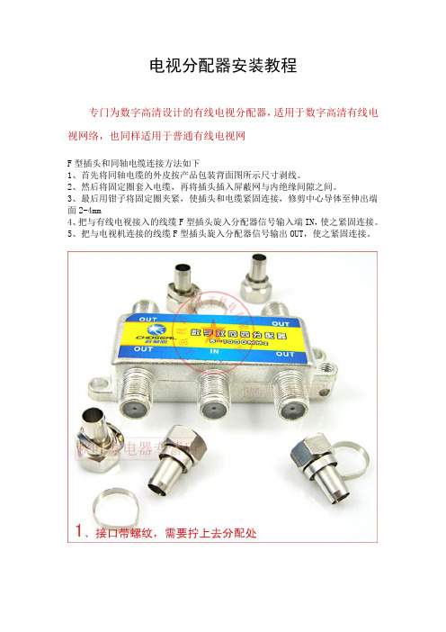
电视分配器安装教程
专门为数字高清设计的有线电视分配器,适用于数字高清有线电视网络,也同样适用于普通有线电视网
F型插头和同轴电缆连接方法如下
1、首先将同轴电缆的外皮按产品包装背面图所示尺寸剥线。
2、然后将固定圈套入电缆,再将插头插入屏蔽网与内绝缘间隙之间。
3、最后用钳子将固定圈夹紧,使插头和电缆紧固连接,修剪中心导体至伸出端面2-4mm
4、把与有线电视接入的线缆F型插头旋入分配器信号输入端IN,使之紧固连接。
5、把与电视机连接的线缆F型插头旋入分配器信号输出OUT,使之紧固连接。
【产品使用说明】
宽带有线电视网络分配器是执行最新的国际数字信号标准采用高质量的磁芯而生产。
它能够有效抑制双向有线电视网络系统内产生的内调干扰。
同时在每个输出输入口进行特别处理以保护系统内某些用户因使用不当导致电视机、游戏机等家用电器的泄露浪涌电流对其它电视机产生的干扰。
【注意事项】
使用时应有足够信号,不能用劣质线材,电线不宜过长;
接线头安装时要正确牢固,使用外导体有良好的接触;
产品出厂已经仪器严格检测,但以上不足均可导致图象不佳。
【产品特性】
低插损、高隔离度、高屏蔽性、5-1000MHZ双向网络产品、锌合金压铸、表面镀镍处理。
- 1、下载文档前请自行甄别文档内容的完整性,平台不提供额外的编辑、内容补充、找答案等附加服务。
- 2、"仅部分预览"的文档,不可在线预览部分如存在完整性等问题,可反馈申请退款(可完整预览的文档不适用该条件!)。
- 3、如文档侵犯您的权益,请联系客服反馈,我们会尽快为您处理(人工客服工作时间:9:00-18:30)。
禁止
按照本手册进行
确定已经接地
警告
在进行电器操作的时候,请联系经销 商,有资格的电工或本公司授权的服 务中心
在拆开包装和安装机器的时候要小心
确保安装面板和控制盒的安全可靠
• 不要私自拆开或修理,这样会引起 • 锋利的边角可能会对您造成伤害,要 • 这样会引起火灾或触电
触电和火灾
特别小心冷凝器和蒸发器的边缘部分
分支管
控制盒盖
C
A
Ø9.52
最小 400
最小 400
(维修操作空间 )
(337) 最小 30
(298) 250
最小 300
悬挂螺钉定位
245
检查口
安装手册 5
分配器的安装
分配器的安装
注意
• 本分配器有2种不同的安装方式 (1) 天花板悬挂式 (2) 墙面固定式 • 根据安装位置选择适当的安装模式 • 根据安装模式的不同内部的电子线路板
15
(总主管长)+(总支管长)
100
h1
30
h2
10
长度
A, B L1+L2+L3+L4+L5+L6+(L7)+(L8) L1, L2, L3, L4, L5, L6, L7,L8 (总主管长)+(总支管长) h1 h2
(m)
7室 8室
50
50
60
80
15
15
110 130
30
30
10
10
(m)
8室
安装位置也要改变
(1) 天花板悬挂式
(1) 天花板悬挂式
(2) 墙面固定式
步骤
(1) 把提供悬挂用的金属片用2个螺钉固定(一共4个位置) (2) 将螺栓插入到孔中 (3) 将六角螺母和垫圈(本地获得)安装到螺栓上(如下图所
示)将金属片悬挂起来 (4) 检查一下是否水平,检查完以后将六角螺母紧固
* 分配器的前/后,左/右倾斜必须在±5度以内
不要踩踏或在机器上堆压任何物品 • 有人身伤害和损坏机器的危险
90û
附件
1. 安装手册
2. 金属吊钩 3. 螺钉
需要准备的零件清单 • 连接线
(H05VV, 4 wires, 0.75mm, or 1.2mm) 1本 • 安装零件
(悬挂螺钉: 4 x M10 or M8, 螺母: 12 垫圈: 8 )
• 由于本分配器内部采用泡沫和低压绝缘管所以不需要排水措施。 维修的位置是B面和C面。(如下图所示)
• 通向室内机的管道在A面附近。 • B面向前或后或边上的倾斜度应当控制±5度之内。
(36) 50 50 50
主管道
B
30 50
(111)
(150)
(38) 50
Ø19.05
72
300
60
(56) 50 50 50
注意 • 不要用塑料帽封口 • 确保在管端口用黄铜帽封口或进行无缝焊接
多支路分配器
室内机管
聚乙烯基带 窄)
分配器接口
铜帽 无缝焊接
安装手册 7
电线的连接
电线的连接
• 将制冷系统配管和连接线路按机器上标明的字母(A、B、C)顺序对应的连接起来 • 按照电路标志牌上面的说明对终端室外机/室内机控制板进行连接,同时每个地线都要用一个
(1) 把提供悬挂用的金属片用2个螺钉固定(一共3个位置)
(2) 检查一下是否水平,检查完后用装配用的木栓固定 * 分配器的前/后,左/右倾斜必须在±5度以内
注意 • 一旦螺孔里面已经有螺钉拧进去了,再次确认一下,如果没有就用铝箔将其盖上(防止变形) • 确认已经安装了天花板 • 不要在靠近卧室的地方安装,因为制冷剂在管道中流动的声音有时候能够被听到
独立的螺钉固定(如下图所示) • 当完成电线连接以后,将线用夹子夹好,室内机上得线夹子已提供。请按下列步骤安装。 • 可以查阅室外机内部控制盒的电路原理图
注意 : 终端控制板上的数字是按从顶部到底部排列的分别是1、2、3
三个房间的示例
A 房间 B 房间 C 房间
A B C CN-PWR
室内机电线的连接 (H05VV, 4wires, 0.75mm)
连接管
用绝缘材料将连接部分包起来
1. 将连接管绝缘材料与室内机管道绝缘材料交叠, 然后用聚乙烯基带绑起来,并 保证没有缺口。
2. 用聚乙烯基带将机架后面的管道也包起来。
空闲房间的接口用铜帽封上
1. 用手将管中心对齐,使得扩口螺母和管紧密的 结合在一起。
2.利用扳手将螺母扳紧。 3. 用绝缘材料将结合处包紧。
P /No.:3828A21040A
安装手册 1
安全注意事项
不要在电源线上面放置任何东西 • 有引起火灾或触电的危险
在机器运行的时候要小心,电线不能被 不要把加热器或其他电器放在电源线
拉拔或损坏
周围
• 有引起火灾或触电的危险
• 有引起火灾或触电的危险
产品要始终接地 • 有引起火灾或触电的危险
用户不要自己安装,移动和重新安装
8 多支管分配器
连接到室内机的排水软管和排水管的连接:
1. 用手将管中心对齐,使得扩口螺母和管紧密的 结合在一起
2.利用扳手将螺母扳紧
外直径
转矩
毫米
英寸
kg.m
6.35
1/4
1.8
9.52
3/8
4.2
12.7
1/2
5.5
15.88
5/8
6.6
19.05
3/4
6.6
分配器接口
扳手 分配器接口
扩口螺母 管路
扳手(固定) 扩口螺母
系统平面图和管长
安装室内机时请参照安装手册里的说明进行安装
系统平图
分配器
制冷剂 房间
2 3 4
R22
APMBD7622 APMBD7632 APMBD7642
不要连接超过8台室内机,根据房间数选择分配盒按以下一种模式安装:
多支管
分配器
分支管
A
L1
L2
L3
L4
h2 多支管 分配器
L5
L6
L7
L8
h1
多支管
MULTI-V
No (1) 主管道长度 (2) 总支管道长度 (3) 最大单独支管长度 (4) 系统管道总长度 (5) 室内外机最大落差 (6) 室内机间最大落差
安装
长度
6室
A+B
50
L1+L2+L3+L4+L5+L6+(L7)+(L8) 50
L1, L2, L3, L4, L5, L6, L7,L8
(2) 墙面固定式
S螺c钉re(wMs5(M) 5) (l本oc地al获ly 得pro) cude)
多支管分配器
S六ix-角sid螺ed母Nut (M10 or M8) H悬an挂ge金r m属e片tal
Flat w垫as圈her
Ha悬ng挂in螺g b栓olt (M10 or M8)
15.00
步骤
2 多支管分配器
如果从产品中发出异常的声音或异常的气味 • 立即把电源断开,否则有发生触电或火灾的危险
安全注意事项 不要在湿度非常高和门窗敞开的时候长时间运转空调
• 湿雾有可能会凝聚,损坏机器
中文版
安装本产品的时候请保持水平 • 避免振动或漏水
注意
每次安装或修理完以后要检查制冷剂 是否有泄漏
• 制冷剂不足会导致机器故障
• 墙面安装螺钉 : 6 x M5 4个 • 绝缘物
• 铜管帽 12个 • 铝箔
安装手册 3
附件
选择安装地点前的准备
这种多支管分配器在室内使用,安装在天花板上面或墙后面等位置需要满足以下条件:
• 机器要有足够的支撑,安装的地方必须振动很小或没有振动 • 室内机和室外机的制冷剂管要能很方便地进行维修,到两边的距离要适当并符合要求 • 周围没有热源或蒸气源 • 安装的时候确定是否有足够的空间以便于将来检修机器 • 不要将机器长时间安装在高温或高湿度的地点 • 安装在一个通风顺畅的区域 • 不要将机器安装在靠近卧室的地方,有时候制冷剂流过管道的时候人耳可以听到
6 多支管分配器
管道的连接
管道的连接
• 和室内机进行连接的时候确保系统制冷配管、连接线根据字母的顺序匹配连接到对应的连接口(A、B、C、D)
注意
• 确保本地所有的制冷系统配管(液体管、气体管等)都要明确 标志清楚指向哪个室内机(A、B、C、D)
A
B
C
D
中文版
注意
为了保证管道正常工作请按照安装手册中的说明进行安装
分配器
分支管
A
L1
L2
L3
L4
h2
L5
L6
L7
L8
h1
40k(6房间)
48k~72k(7~8房间)
MPS
* Y支管 (可选) 主管道
B
70k~150k(2~8房间)
MULTI-V
主管道
B
4 多支管分配器
中文版
管道长度和高度
MPS
No (1) 主管道长度 (2) 总支管道长度 (3) 最大单独支管长度 (4) 系统管道总长度 (5) 室内外机最大落差 (6) 室内机间最大落差
多支管分配器 安装手册
APMBD7622/APMBD7632/APMBD7642
安全注意事项
为了防止对用户或其他人员造成伤害,请严格按照本手册进行操作 忽视手册的误操作会造成伤害和破坏,以下就危险程度作了说明
警告
这个符号表示易导致死亡或严重人身伤害
