ATmega128(L)单片机开发板原理图
第2章_ATmega128硬件结构
广州大学 机电学院 庞志
$100CA
$1006:LDI R1,$0A $1008:LDS R2,$FF00 $100A:ADD R2,R1 $100C:STS $$FFFF0000(($$110A)) $FF00,R2
R1=$0A R2=$$11AA0
2020年5月19日星期二
广州大学 机电学院 庞志
广州大学 机电学院 庞志
ATmega128
单 片 机 方 框 图
2020年5月19日星期二
广州大学 机电学院 庞志
ATmega128
单 片 机 指 令 执 行 过 程
2020年5月19日星期二
广州大学 机电学院 庞志
$1006
10+(0xFF00$)1=0>0(60:xLFDFI 0R0)1,$0A
当RAMPZ0=1: ELPM/SPM可以访问程序存储器地址 $8000——$FFFF(高64K字节)
2020年5月19日星期二
广州大学 机电学院 庞志
2.2.3 指令执行时序
AVR CPU由系统时钟clkCPU驱动。
并行取指和执行时序
2020年5月19日星期二
广州大学 机电学院 庞志
单时钟周期ALU 操作
模拟比较器
2020年5月19日星期二
广州大学 机电学院 庞志
2.1.2 主要性能 (续)
特殊的处理器特点
上电复位 可编程的掉电检测 片内RC振荡器 片内/片外中断源 6种睡眠模式: 空闲模式、ADC噪声抑制模式、省电模
式、掉电模式、Standby模式以及扩展的Standby模式 可选的时钟频率 可选ATmega103兼容模式 全局上拉禁止功能
Bit 6 – T: 位拷贝存储 Bit 4 – S: 符号位,S=N⊕V Bit 2 – N: 负数标志 Bit 0 – C: 进位标志
ATmega128 单片机硬件电路设计
ATmega128 单片机硬件电路设计在本系统中,本小节主要讲ATmega128 单片机的内部资源、工作原理和硬件电路设计等。
2.5.1 ATmega128 芯片介绍ATmega128 为基于AVR RISC 结构的8 位低功耗CMOS 微处理器。
片内ISP Flash 可以通过SPI 接口、通用编程器,或引导程序多次编程。
引导程序可以使用任何接口来下载应用程序到应用Flash 存储器。
通过将8 位RISC CPU 与系统内可编程的Flash 集成在一个芯片内,ATmega128 为许多嵌入式控制应用提供了灵活而低成本的方案。
ATmega128 单片机的功能特点如下:(1)高性能、低功耗的AVR 8 位微处理器(2)先进的RISC 结构①133 条指令大多数可以在一个时钟周期内完成② 32x8 个通用工作寄存器+外设控制寄存器③全静态工作④工作于16 MHz 时性能高达16 MIPS ⑤只需两个时钟周期的硬件乘法器(3)非易失性的程序和数据存储器① 128K 字节的系统内可编程Flash ②寿命: 10,000 次写/ 擦除周期③具有独立锁定位、可选择的启动代码区(4)通过片内的启动程序实现系统内编程① 4K 字节的EEPROM ② 4K 字节的内部SRAM ③多达64K 字节的优化的外部存储器空间④可以对锁定位进行编程以实现软件加密⑤可以通过SPI 实现系统内编程(5)JTAG 接口(与IEEE 1149.1 标准兼容)①遵循JTAG 标准的边界扫描功能②支持扩展的片内调试③通过JTAG 接口实现对Flash,EEPROM,熔丝位和锁定位的编程(6)外设特点①两个具有独立的预分频器和比较器功能的8 位定时器/ 计数器②两个具有预分频器、比较功能和捕捉功能的16 位定时器/ 计数器③具有独立预分频器的实时时钟计数器④两路8 位PWM ⑤ 6 路分辨率可编程(2 到16 位)的PWM ⑥输出比较调制器⑦ 8 路10 位ADC ⑧面向字节的两线接口⑨两个可编程的串行USART ⑩可工作于主机/ 从机模式的SPI 串行接口(7)特殊的处理器特点①上电复位以及可编程的掉电检测②片内经过标定的RC 振荡器③片内/ 片外中断源④ 6 种睡眠模式: 空闲模式、ADC 噪声抑制模式、省电模式、掉电模式、Standby 模式以及扩展的Standby 模式⑤可以通过软件进行选择的时钟频率⑥通过熔丝位可以选择ATmega103 兼容模式⑦全局上拉禁止功能ATmega128 芯片有64 个引脚,其中60 个引脚具有I/O 口功能,资源比较丰富,下面对ATmega128 的各个引脚做简单介绍:VCC:数字电路的电源。
ATMEGA128实验开发板用户手册

ATMEGA128实验开发板用户手册V1.32011年5月E-mail: sdfdlut@1. ATMEGA128单片机概述ATMEGA128单片机是ATMEL公司推出的一款基于AVR内核,采用RISC结构,低功耗CMOS的8位单片机。
由于在一个周期内执行一条指令,ATMEGA128可以达到接近1MIPS/MHz的性能。
其内核将32个工作寄存器和丰富的指令集联结在一起,所有的工作寄存器都与ALU(逻辑单元)直接连接,实现了在一个时钟周期内执行一条指令可以同时访问两个独立的寄存器。
这种结构提高了代码效率,是AVR的运行速度比普通的CISC单片机高出10倍。
ATMEGA128单片机具有以下特点:128KB的可在系统编程/应用编程(ISP/IAP)Flash 程序存储器,4KB E2PROM,4KB SRAM,32个通用工作寄存器,53个通用I/O口,实时时钟计数器(RTC),4个带有比较模式灵活的定时器/计数器,2个可编程的USART接口,一个8为面向字节的TWI(I2C)总线接口,8通道单端或差分输入的10位ADC(其中一个差分通道为增益可调),可编程带内部振荡器的看门狗定时器,一个SPI接口,一个兼容IEEE 1149.1标准的JTAG接口(用于在线仿真调试和程序下载),6种可通过软件选择的节电模式。
2. ATMEGA128实验开发套件本实验开发套件包括:●测试通过的MEGA128实验板1块;●配套资料光盘1张;●AVR ISP并口下载线1条;●5110液晶模块1个;●遥控器1个;●USB ASP下载线(选配);●AVR JTAGICE仿真器(选配)。
其中资料光盘的内容主要包括:●ATMEGA128实验开发板用户手册.pdf(本文档);●AVR教程:⏹WINAVR 使用入门.pdf⏹AVR Studio 使用入门.pdf⏹AVR基本硬件线路设计与分析.pdf⏹芯艺的AVR_GCC教程.pdf⏹AVR的IO结构分析与范例.mht⏹AVR高速嵌入式单片机原理与应用●芯片手册(包括24C02、74HC595以及中文的I2C协议文档等内容)●开发工具软件;⏹AVR Studio V4.12;⏹WINAVR(GCC) 编译器;⏹IAR for AVR V4.10A;⏹并口下载工具PONYPROG V2.06;⏹ICCAVR 双龙提供;图3 新建工程对话框点击Next,进入第三步。
atmega128芯片资料(英文)

1Features•High-performance, Low-power AVR ® 8-bit Microcontroller •Advanced RISC Architecture–133 Powerful Instructions – Most Single Clock Cycle Execution–32 x 8 General Purpose Working Registers + Peripheral Control Registers –Fully Static Operation–Up to 16 MIPS Throughput at 16 MHz –On-chip 2-cycle Multiplier•Nonvolatile Program and Data Memories–128K Bytes of In-System Reprogrammable FlashEndurance: 1,000 Write/Erase Cycles–Optional Boot Code Section with Independent Lock BitsIn-System Programming by On-chip Boot Program True Read-While-Write Operation –4K Bytes EEPROMEndurance: 100,000 Write/Erase Cycles –4K Bytes Internal SRAM–Up to 64K Bytes Optional External Memory Space –Programming Lock for Software Security –SPI Interface for In-System Programming •JTAG (IEEE std. 1149.1 Compliant) Interface–Boundary-scan Capabilities According to the JTAG Standard –Extensive On-chip Debug Support–Programming of Flash, EEPROM, Fuses and Lock Bits through the JTAG Interface •Peripheral Features–Two 8-bit Timer/Counters with Separate Prescalers and Compare Modes–Two Expanded 16-bit Timer/Counters with Separate Prescaler, Compare Mode and Capture Mode–Real Time Counter with Separate Oscillator –Two 8-bit PWM Channels–6 PWM Channels with Programmable Resolution from 1 to 16 Bits –8-channel, 10-bit ADC8 Single-ended Channels 7 Differential Channels2 Differential Channels with Programmable Gain (1x, 10x, 200x)–Byte-oriented 2-wire Serial Interface –Dual Programmable Serial USARTs –Master/Slave SPI Serial Interface–Programmable Watchdog Timer with On-chip Oscillator –On-chip Analog Comparator •Special Microcontroller Features–Power-on Reset and Programmable Brown-out Detection –Internal Calibrated RC Oscillator–External and Internal Interrupt Sources–Six Sleep Modes: Idle, ADC Noise Reduction, Power-save, Power-down, Standby and Extended Standby–Software Selectable Clock Frequency–ATmega103 Compatibility Mode Selected by a Fuse –Global Pull-up Disable •I/O and Packages–53 Programmable I/O Lines –64-lead TQFP •Operating Voltages–2.7 - 5.5V (ATmega128L)–4.5 - 5.5V (ATmega128)•Speed Grades–0 - 8 MHz (ATmega128L)–0 - 16 MHz (ATmega128)Rev. 2467AS-08/01Microcontroller with 128K Bytes In-SystemProgrammable ATmega128ATmega128L Preliminary SummaryNote: This is a summary document. A complete document is available on our web site at .2ATmega128(L)2467AS –08/01Pin ConfigurationsFigure 1. Pinout ATmega128OverviewThe ATmega128 is a low-power CMOS 8-bit microcontroller based on the AVR enhanced RISC architecture. By executing powerful instructions in a single clock cycle,the ATmega128 achieves throughputs approaching 1 MIPS per MHz allowing the sys-tem designer to optimize power consumption versus processing speed.3ATmega128(L)2467AS –08/01Block DiagramFigure 2. Block Diagram4ATmega128(L)2467AS –08/01The AVR core combines a rich instruction set with 32 general purpose working registers.All the 32 registers are directly connected to the Arithmetic Logic Unit (ALU), allowing two independent registers to be accessed in one single instruction executed in one clock cycle. The resulting architecture is more code efficient while achieving throughputs up to ten times faster than conventional CISC microcontrollers.The ATmega128 provides the following features: 128K bytes of In-System Programma-ble Flash with Read-While-Write capabilities, 4K bytes EEPROM, 4K bytes SRAM, 53general-purpose I/O lines, 32 general purpose working registers, Real Time Counter (RTC), four flexible timer/counters with compare modes and PWM, 2 USARTs, a byte oriented 2-wire Serial Interface, an 8-channel, 10-bit ADC with optional differential input stage with programmable gain, programmable Watchdog Timer with internal oscillator,an SPI serial port, IEEE std. 1149.1 compliant JTAG test interface, also used for accessing the On-chip Debug system and programming and six software selectable power saving modes. The Idle mode stops the CPU while allowing the SRAM,timer/counters, SPI port, and interrupt system to continue functioning. The Power-down mode saves the register contents but freezes the oscillator, disabling all other chip func-tions until the next interrupt or hardware reset. In Power-save mode, the asynchronous timer continues to run, allowing the user to maintain a timer base while the rest of the device is sleeping. The ADC Noise Reduction Mode stops the CPU and all I/O modules except asynchronous timer and ADC, to minimize switching noise during ADC conver-sions. In Standby mode, the crystal/resonator oscillator is running while the rest of the device is sleeping. This allows very fast start-up combined with low power consumption.In Extended Standby mode, both the main oscillator and the asynchronous timer con-tinue to run.The device is manufactured using Atmel ’s high-density nonvolatile memory technology.The on-chip ISP Flash allows the program memory to be reprogrammed in-system through an SPI serial interface, by a conventional nonvolatile memory programmer, or by an on-chip Boot program running on the AVR core. The boot program can use any interface to download the application program in the application Flash memory. Soft-ware in the Boot Flash section will continue to run while the Application Flash section is updated, providing true Read-While-Write operation. By combining an 8-bit RISC CPU with In-System Self-Programmable Flash on a monolithic chip, the Atmel ATmega128 is a powerful microcontroller that provides a highly flexible and cost effective solution to many embedded control applications.The ATmega128 AVR is supported with a full suite of program and system development tools including: C compilers, macro assemblers, program debugger/simulators, in-circuit emulators, and evaluation kits.ATmega103 and ATmega128 CompatibilityThe ATmega128 is a highly complex microcontroller where the number of I/O locations supersedes the 64 I/O location reserved in the AVR instruction set. To ensure backward compatibility with the ATmega103, all I/O locations present in ATmega103 have the same location in ATmega128. Most additional I/O locations are added in an Extended I/O space starting from $60 to $FF, (i.e., in the ATmega103 internal RAM space). These location can be reached by using LD/LDS/LDD and ST/STS/STD instruction only, not by using IN and OUT instruction. The relocation of the internal RAM space may still be a problem for ATmega103 users. Also, the increased number of interrupt vectors might be a problem if the code uses absolute addresses. To solve these problems, an ATmega103 compatibility mode can be selected by programming the fuse M103C. In this mode, none of the functions in the Extended I/O space are in use, so the internal RAM is located as in ATmega103. Also, the extended interrupt vectors are removed.5ATmega128(L)2467AS –08/01The ATmega128 is 100% pin compatible with ATmega103, and can replace the ATmega103 on current Printed Circuit Boards. The application note “Replacing ATmega103 by ATmega128” describes what the user should be aware of replacing the ATmega103 by an ATmega128.ATmega103 Compatibility ModeBy programming the M103C fuse, the ATmega128 will be compatible with the ATmega103 regards to RAM, I/O pins and interrupt vectors as described above. How-ever, some new features in ATmega128 are not available in this compatibility mode,these features are listed below:•One USART instead of two, asynchronous mode only. Only the 8 least significant bits of the Baud Rate Register is available.•One 16 bits Timer/Counter with 2 compare registers instead of two 16-bit Timer/Counters with 3 compare registers.•2-wire serial interface is not supported.•Port G serves alternate functions only (not a general I/O port).•Port F serves as digital input only in addition to analog input to the ADC.•Boot Loader capabilities is not supported.•It is not possible to adjust the frequency of the internal calibrated RC oscillator.•The External Memory Interface can not release any Address pins for general I/O, neither configure different wait-states to different External Memory Address sections.Pin DescriptionsVCC Digital supply voltage.GNDGround.Port A (PA7..PA0)Port A is an 8-bit bi-directional I/O port with internal pull-up resistors (selected for each bit). The Port A output buffers have symmetrical drive characteristics with both high sink and source capability. As inputs, Port A pins that are externally pulled low will source current if the pull-up resistors are activated. The Port A pins are tri-stated when a reset condition becomes active, even if the clock is not running.Port A also serves the functions of various special features of the ATmega128 as listed on page 68.Port B (PB7..PB0)Port B is an 8-bit bi-directional I/O port with internal pull-up resistors (selected for each bit). The Port B output buffers have symmetrical drive characteristics with both high sink and source capability. As inputs, Port B pins that are externally pulled low will source current if the pull-up resistors are activated. The Port B pins are tri-stated when a reset condition becomes active, even if the clock is not running.Port B also serves the functions of various special features of the ATmega128 as listed on page 69.Port C (PC7..PC0)Port C is an 8-bit bi-directional I/O port with internal pull-up resistors (selected for each bit). The Port C output buffers have symmetrical drive characteristics with both high sink and source capability. As inputs, Port C pins that are externally pulled low will source current if the pull-up resistors are activated. The Port C pins are tri-stated when a reset condition becomes active, even if the clock is not running.6ATmega128(L)2467AS –08/01Port C also serves the functions of special features of the ATmega128 as listed on page 72. In ATmega103 compatibility mode, Port C is output only, and the port C pins are not tri-stated when a reset condition becomes active.Port D (PD7..PD0)Port D is an 8-bit bidirectional I/O port with internal pull-up resistors (selected for each bit). The Port D output buffers have symmetrical drive characteristics with both high sink and source capability. As inputs, Port D pins that are externally pulled low will source current if the pull-up resistors are activated. The Port D pins are tri-stated when a reset condition becomes active, even if the clock is not running.Port D also serves the functions of various special features of the ATmega128 as listed on page 73.Port E (PE7..PE0)Port E is an 8-bit bidirectional I/O port with internal pull-up resistors (selected for each bit). The Port E output buffers have symmetrical drive characteristics with both high sink and source capability. As inputs, Port E pins that are externally pulled low will source current if the pull-up resistors are activated. The Port E pins are tri-stated when a reset condition becomes active, even if the clock is not running.Port E also serves the functions of various special features of the ATmega128 as listed on page 76.Port F (PF7..PF0)Port F serves as the analog inputs to the A/D Converter.Port F also serves as an 8-bit bi-directional I/O port, if the A/D Converter is not used.Port pins can provide internal pull-up resistors (selected for each bit). The Port F output buffers have symmetrical drive characteristics with both high sink and source capability.As inputs, Port F pins that are externally pulled low will source current if the pull-up resistors are activated. The Port F pins are tri-stated when a reset condition becomes active, even if the clock is not running. If the JTAG interface is enabled, the pull-up resis-tors on pins PF7(TDI), PF5(TMS) and PF4(TCK) will be activated even if a reset occurs.Port F also serves the functions of the JTAG interface.In ATmega103 compatibility mode, Port F is an input Port only.Port G (PG4..PG0)Port G is a 5-bit bidirectional I/O port with internal pull-up resistors (selected for each bit). The Port G output buffers have symmetrical drive characteristics with both high sink and source capability. As inputs, Port G pins that are externally pulled low will source current if the pull-up resistors are activated. The Port G pins are tri-stated when a reset condition becomes active, even if the clock is not running.Port G also serves the functions of various special features.The port G pins are tri-stated when a reset condition becomes active, even if the clock is not running.In ATmega103 compatibility mode, these pins only serves as strobes signals to the external memory as well as input to the 32 kHz oscillator, and the pins are initialized to PG0 = 1, PG1 = 1, and PG2 = 0 asynchronously when a reset condition becomes active,even if the clock is not running. PG3 and PG4 are oscillator pins.RESETReset input. A low level on this pin for longer than the minimum pulse length will gener-ate a reset, even if the clock is not running. The minimum pulse length is given in Table 19 on page 46. Shorter pulses are not guaranteed to generate a reset.XTAL1Input to the inverting oscillator amplifier and input to the internal clock operating circuit.7ATmega128(L)2467AS –08/01XTAL2Output from the inverting oscillator amplifier.AVCCThis is the supply voltage pin for Port F and the A/D Converter. It should be externally connected to VCC, even if the ADC is not used. If the ADC is used, it should be con-nected to VCC through a low-pass filter.AREF This is the analog reference pin for the A/D Converter.PENThis is a programming enable pin for the serial programming mode. By holding this pin low during a power-on reset, the device will enter the serial programming mode. PEN has no function during normal operation.8ATmega128(L)2467AS –08/01Register SummaryAddressNameBit 7Bit 6Bit 5Bit 4Bit 3Bit 2Bit 1Bit 0Page($FF)Reserved --------..Reserved --------($9E)Reserved --------($9D)UCSR1C -UMSEL1UPM11UPM10USBS1UCSZ11UCSZ10UCPOL1185($9C)UDR1USART1 I/O Data Register182($9B)UCSR1A RXC1TXC1UDRE1FE1DOR1UPE1U2X1MPCM1183($9A)UCSR1B RXCIE1TXCIE1UDRIE1RXEN1TXEN1UCSZ12RXB81TXB81184($99)UBRR1L USART1 Baud Rate Register Low186($98)UBRR1H ----USART1 Baud Rate Register High186($97)Reserved --------($96)Reserved --------($95)UCSR0C -UMSEL0UPM01UPM00USBS0UCSZ01UCSZ00UCPOL0185($94)Reserved --------($93)Reserved --------($92)Reserved --------($91)Reserved --------($90)UBRR0H ----USART0 Baud Rate Register High186($8F)Reserved --------($8E)Reserved --------($8D)Reserved --------($8C)TCCR3C FOC3A FOC3B FOC3C -----132($8B)TCCR3A COM3A1COM3A0COM3B1COM3B0COM3C1COM3C0WGM31WGM30127 ($8A)TCCR3B ICNC3ICES3-WGM33WGM32CS32CS31CS30130($89)TCNT3H Timer/Counter3 - Counter Register High Byte 132 ($88)TCNT3L Timer/Counter3 - Counter Register Low Byte132 ($87)OCR3AH Timer/Counter3 - Output Compare Register A High Byte 133($86)OCR3AL Timer/Counter3 - Output Compare Register A Low Byte 133($85)OCR3BH Timer/Counter3 - Output Compare Register B High Byte 133($84)OCR3BL Timer/Counter3 - Output Compare Register B Low Byte 133($83)OCR3CH Timer/Counter3 - Output Compare Register C High Byte 133($82)OCR3CL Timer/Counter3 - Output Compare Register C Low Byte 133($81)ICR3H Timer/Counter3 - Input Capture Register High Byte 134($80)ICR3L Timer/Counter3 - Input Capture Register Low Byte134($7F)Reserved --------($7E)Reserved --------($7D)ETIMSK --TICIE3OCIE3A OCIE3B TOIE3OCIE3C OCIE1C 135 ($7C)ETIFR --ICF3OCF3A OCF3B TOV3OCF3COCF1C136($7B)Reserved --------($7A)TCCR1C FOC1AFOC1BFOC1C-----131($79)OCR1CH Timer/Counter1 - Output Compare Register C High Byte 133($78)OCR1CL Timer/Counter1 - Output Compare Register C Low Byte133($77)Reserved --------($76)Reserved --------($75)Reserved --------($74)TWCR TWINT TWEA TWSTA TWSTO TWWC TWEN -TWIE 198($73)TWDR 2-wire Serial Interface Data Register199($72)TWAR TWA6TWA5TWA4TWA3TWA2TWA1TWA0TWGCE 200($671TWSR TWS7TWS6TWS5TWS4TWS3-TWPS1TWPS0199($70)TWBR 2-wire Serial Interface Bit Rate Register 197($6F)OSCCAL Oscillator Calibration Register38($6E)Reserved --------($6D)XMCRA -SRL2SRL1SRL0SRW01SRW00SRW1129($6C)XMCRB XMBK ----XMM2XMM1XMM031($6B)Reserved --------($6A)EICRA ISC31ISC30ISC21ISC20ISC11ISC10ISC01ISC0084($69)Reserved --------($68)SPMCSR SPMIE RWWSB-RWWSREBLBSETPGWRTPGERSSPMEN270($67)Reserved --------($66)Reserved --------($65)PORTG ---PORTG4PORTG3PORTG2PORTG1PORTG083($64)DDRG ---DDG4DDG3DDG2DDG1DDG083($63)PING ---PING4PING3PING2PING1PING083($62)PORTFPORTF7PORTF6PORTF5PORTF4PORTF3PORTF2PORTF1PORTF0839ATmega128(L)2467AS –08/01($61)DDRF DDF7DDF6DDF5DDF4DDF3DDF2DDF1DDF083($60)Reserved --------$3F ($5F)SREG I T H S V N Z C 9$3E ($5E)SPH SP15SP14SP13SP12SP11SP10SP9SP812$3D ($5D)SPL SP7SP6SP5SP4SP3SP2SP1SP012$3C ($5C)XDIV XDIVENXDIV6XDIV5XDIV4XDIV3XDIV2XDIV1XDIV039$3B ($5B)RAMPZ -------RAMPZ012$3A ($5A)EICRB ISC71ISC70ISC61ISC60ISC51ISC50ISC41ISC4085$39 ($59)EIMSK INT7INT6INT5INT4INT3INT2INT1INT086$38 ($58)EIFR INTF7INTF6INTF5INTF4INTF3INTF INTF1INTF086$37 ($57)TIMSK OCIE2TOIE2TICIE1OCIE1A OCIE1B TOIE1OCIE0TOIE0103, 134, 153$36 ($56)TIFR OCF2TOV2ICF1OCF1A OCF1B TOV1OCF0TOV0103, 136, 154$35 ($55)MCUCR SRE SRW10SE SM1SM0SM2IVSEL IVCE 29, 41, 58 $34 ($54)MCUCSR JTD --JTRF WDRF BORF EXTRF PORF 49, 246$33 ($53)TCCR0FOC0WGM00COM01COM00WGM01CS02CS01CS0098$32 ($52)TCNT0 Timer/Counter0 (8 Bit)100$31 ($51)OCR0 Timer/Counter0 Output Compare Register100$30 ($50)ASSR ----AS0TCN0UB OCR0UB TCR0UB 101$2F ($4F)TCCR1A COM1A1COM1A0COM1B1COM1B0COM1C1COM1C0WGM11WGM10127$2E ($4E)TCCR1B ICNC1ICES1-WGM13WGM12CS12CS11CS10130$2D ($4D)TCNT1H Timer/Counter1 - Counter Register High Byte 132$2C ($4C)TCNT1L Timer/Counter1 - Counter Register Low Byte132$2B ($4B)OCR1AH Timer/Counter1 - Output Compare Register A High Byte 133$2A ($4A)OCR1AL Timer/Counter1 - Output Compare Register A Low Byte 133$29 ($49)OCR1BH Timer/Counter1 - Output Compare Register B High Byte 133$28 ($48)OCR1BL Timer/Counter1 - Output Compare Register B Low Byte 133$27 ($47)ICR1H Timer/Counter1 - Input Capture Register High Byte 134$26 ($46)ICR1L Timer/Counter1 - Input Capture Register Low Byte 134$25 ($45)TCCR2FOC2WGM20COM21COM20WGM21CS22CS21CS20151$24 ($44)TCNT2Timer/Counter2 (8 Bit)153$23 ($43)OCR2Timer/Counter2 Output Compare Register 153$22 ($42)OCDR IDRD/OCDR7OCDR6OCDR5OCDR4OCDR3OCDR2OCDR1OCDR0242$21 ($41)WDTCR ---WDCE WDE WDP2WDP1WDP051$20 ($40)SFIOR TSM --ADHSMACMEPUDPSR0PSR32167, 104, 139, 237$1F ($3F)EEARH ----EEPROM Address Register High19$1E ($3E)EEARL EEPROM Address Register Low Byte 19$1D ($3D)EEDR EEPROM Data Register20$1C ($3C)EECR ----EERIE EEMWE EEWE EERE 20$1B ($3B)PORTA PORTA7PORTA6PORTA5PORTA4PORTA3PORTA2PORTA1PORTA081$1A ($3A)DDRA DDA7DDA6DDA5DDA4DDA3DDA2DDA1DDA081$19 ($39)PINA PINA7PINA6PINA5PINA4PINA3PINA2PINA1PINA081$18 ($38)PORTB PORTB7PORTB6PORTB5PORTB4PORTB3PORTB2PORTB1PORTB081$17 ($37)DDRB DDB7DDB6DDB5DDB4DDB3DDB2DDB1DDB081$16 ($36)PINB PINB7PINB6PINB5PINB4PINB3PINB2PINB1PINB082$15 ($35)PORTC PORTC7PORTC6PORTC5PORTC4PORTC3PORTC2PORTC1PORTC082$14 ($34)DDRC DDC7DDC6DDC5DDC4DDC3DDC2DDC1DDC082$13 ($33)PINC PINC7PINC6PINC5PINC4PINC3PINC2PINC1PINC082$12 ($32)PORTD PORTD7PORTD6PORTD5PORTD4PORTD3PORTD2PORTD1PORTD082$11 ($31)DDRD DDD7DDD6DDD5DDD4DDD3DDD2DDD1DDD082$10 ($30)PIND PIND7PIND6PIND5PIND4PIND3PIND2PIND1PIND082$0F ($2F)SPDR SPI Data Register163$0E ($2E)SPSR SPIF WCOL -----SPI2X 162$0D ($2D)SPCR SPIE SPE DORD MSTR CPOL CPHA SPR1SPR0161$0C ($2C)UDR0 USART0 I/O Data Register182$0B ($2B)UCSR0A RXC0TXC0UDRE0FE0DOR0UPE0U2X0MPCM0183$0A ($2A)UCSR0B RXCIE0TXCIE0UDRIE0RXEN0TXEN0UCSZ02RXB80TXB80184$09 ($29)UBRR0L USART0 Baud Rate Register Low186$08 ($28)ACSR ACD ACBG ACO ACI ACIE ACIC ACIS1ACIS0218$07 ($27)ADMUX REFS1REFS0ADLAR MUX4MUX3MUX2MUX1MUX0233$06 ($26)ADCSRA ADENADSCADRFADIFADIEADPS2ADPS1ADPS0235$05 ($25)ADCH ADC Data Register High Byte 236$04 ($24)ADCL ADC Data Register Low byte 236$03 ($23)PORTE PORTE7PORTE6PORTE5PORTE4PORTE3PORTE2PORTE1PORTE082$02 ($22)DDREDDE7DDE6DDE5DDE4DDE3DDE2DDE1DDE083Register Summary (Continued)AddressNameBit 7Bit 6Bit 5Bit 4Bit 3Bit 2Bit 1Bit 0Page10ATmega128(L)2467AS –08/01Notes:1.For compatibility with future devices, reserved bits should be written to zero if accessed. Reserved I/O memory addressesshould never be written.2.Some of the status flags are cleared by writing a logical one to them. Note that the CBI and SBI instructions will operate onall bits in the I/O register, writing a one back into any flag read as set, thus clearing the flag. The CBI and SBI instructions work with registers $00 to $1F only.$01 ($21)PINE PINE7PINE6PINE5PINE4PINE3PINE2PINE1PINE083$00 ($20)PINFPINF7PINF6PINF5PINF4PINF3PINF2PINF1PINF083Register Summary (Continued)AddressNameBit 7Bit 6Bit 5Bit 4Bit 3Bit 2Bit 1Bit 0Page11ATmega128(L)2467AS –08/01Instruction Set SummaryMnemonicsOperandsDescriptionOperationFlags#ClocksARITHMETIC AND LOGIC INSTRUCTIONSADD Rd, Rr Add two RegistersRd ← Rd + Rr Z,C,N,V,H 1ADC Rd, Rr Add with Carry two Registers Rd ← Rd + Rr + C Z,C,N,V,H 1ADIW Rdl,K Add Immediate to Word Rdh:Rdl ← Rdh:Rdl + K Z,C,N,V,S 2SUB Rd, Rr Subtract two RegistersRd ← Rd - Rr Z,C,N,V,H 1SUBI Rd, K Subtract Constant from Register Rd ← Rd - K Z,C,N,V,H 1SBC Rd, Rr Subtract with Carry two Registers Rd ← Rd - Rr - C Z,C,N,V,H 1SBCI Rd, K Subtract with Carry Constant from Reg.Rd ← Rd - K - C Z,C,N,V,H 1SBIW Rdl,K Subtract Immediate from Word Rdh:Rdl ← Rdh:Rdl - K Z,C,N,V,S 2AND Rd, Rr Logical AND RegistersRd ← Rd • Rr Z,N,V 1ANDI Rd, K Logical AND Register and Constant Rd ← Rd • K Z,N,V 1OR Rd, Rr Logical OR RegistersRd ← Rd v Rr Z,N,V 1ORI Rd, K Logical OR Register and Constant Rd ← Rd v K Z,N,V 1EOR Rd, Rr Exclusive OR Registers Rd ← Rd ⊕ Rr Z,N,V 1COM Rd One ’s Complement Rd ← $FF − Rd Z,C,N,V 1NEG Rd Two ’s Complement Rd ← $00 − Rd Z,C,N,V,H 1SBR Rd,K Set Bit(s) in Register Rd ← Rd v K Z,N,V 1CBR Rd,K Clear Bit(s) in Register Rd ← Rd • ($FF - K)Z,N,V 1INC Rd Increment Rd ← Rd + 1Z,N,V 1DEC Rd DecrementRd ← Rd − 1 Z,N,V 1TST Rd Test for Zero or Minus Rd ← Rd • Rd Z,N,V 1CLR Rd Clear Register Rd ← Rd ⊕ Rd Z,N,V 1SER Rd Set Register Rd ← $FF None 1MUL Rd, Rr Multiply Unsigned R1:R0 ← Rd x Rr Z,C 2MULS Rd, Rr Multiply SignedR1:R0 ← Rd x Rr Z,C 2MULSU Rd, Rr Multiply Signed with Unsigned R1:R0 ← Rd x Rr Z,C 2FMUL Rd, Rr Fractional Multiply Unsigned R1:R0 ← (Rd x Rr) << 1Z,C 2FMULS Rd, Rr Fractional Multiply SignedR1:R0 ← (Rd x Rr) << 1Z,C 2FMULSU Rd, Rr Fractional Multiply Signed with Unsigned R1:R0 ← (Rd x Rr) << 1Z,C 2BRANCH INSTRUCTIONSRJMP kRelative Jump PC ← PC + k + 1None 2IJMP Indirect Jump to (Z)PC ← Z None 2JMP k Direct JumpPC ← kNone 3RCALL kRelative Subroutine Call PC ← PC + k + 1None 3ICALL Indirect Call to (Z)PC ← Z None 3CALL k Direct Subroutine Call PC ← k None 4RET Subroutine Return PC ← STACK None 4RETI Interrupt Return PC ← STACKI 4CPSE Rd,Rr Compare, Skip if Equal if (Rd = Rr) PC ← PC + 2 or 3None 1 / 2 / 3CP Rd,Rr CompareRd − Rr Z, N,V,C,H 1 CPC Rd,Rr Compare with CarryRd − Rr − C Z, N,V,C,H 1CPI Rd,K Compare Register with Immediate Rd − KZ, N,V,C,H 1SBRC Rr, b Skip if Bit in Register Cleared if (Rr(b)=0) PC ← PC + 2 or 3 None 1 / 2 / 3SBRS Rr, b Skip if Bit in Register is Set if (Rr(b)=1) PC ← PC + 2 or 3None 1 / 2 / 3SBIC P, b Skip if Bit in I/O Register Cleared if (P(b)=0) PC ← PC + 2 or 3 None 1 / 2 / 3SBIS P, b Skip if Bit in I/O Register is Set if (P(b)=1) PC ← PC + 2 or 3None 1 / 2 / 3BRBS s, k Branch if Status Flag Set if (SREG(s) = 1) then PC ←PC+k + 1None 1 / 2BRBC s, k Branch if Status Flag Cleared if (SREG(s) = 0) then PC ←PC+k + 1None 1 / 2BREQ k Branch if Equal if (Z = 1) then PC ← PC + k + 1None 1 / 2BRNE k Branch if Not Equal if (Z = 0) then PC ← PC + k + 1None 1 / 2BRCS k Branch if Carry Set if (C = 1) then PC ← PC + k + 1None 1 / 2BRCC k Branch if Carry Cleared if (C = 0) then PC ← PC + k + 1None 1 / 2BRSH k Branch if Same or Higher if (C = 0) then PC ← PC + k + 1None 1 / 2BRLO k Branch if Lower if (C = 1) then PC ← PC + k + 1None 1 / 2BRMI k Branch if Minus if (N = 1) then PC ← PC + k + 1None 1 / 2BRPL k Branch if Plusif (N = 0) then PC ← PC + k + 1None 1 / 2BRGE k Branch if Greater or Equal, Signed if (N ⊕ V= 0) then PC ← PC + k + 1None 1 / 2BRLT k Branch if Less Than Zero, Signed if (N ⊕ V= 1) then PC ← PC + k + 1None 1 / 2BRHS k Branch if Half Carry Flag Set if (H = 1) then PC ← PC + k + 1None 1 / 2BRHC k Branch if Half Carry Flag Cleared if (H = 0) then PC ← PC + k + 1None 1 / 2BRTS k Branch if T Flag Set if (T = 1) then PC ← PC + k + 1None 1 / 2BRTC k Branch if T Flag Cleared if (T = 0) then PC ← PC + k + 1None 1 / 2BRVS k Branch if Overflow Flag is Set if (V = 1) then PC ← PC + k + 1None 1 / 2BRVCk Branch if Overflow Flag is Clearedif (V = 0) then PC ← PC + k + 1None1 / 212ATmega128(L)2467AS –08/01MnemonicsOperandsDescriptionOperationFlags#ClocksBRIE k Branch if Interrupt Enabled if ( I = 1) then PC ← PC + k + 1None 1 / 2BRID k Branch if Interrupt Disabled if ( I = 0) then PC ← PC + k + 1None 1 / 2DATA TRANSFER INSTRUCTIONSMOV Rd, Rr Move Between Registers Rd ← RrNone 1MOVW Rd, Rr Copy Register Word Rd+1:Rd ← Rr+1:Rr None 1LDI Rd, K Load Immediate Rd ← K None 1LD Rd, X Load IndirectRd ← (X)None 2LD Rd, X+Load Indirect and Post-Inc.Rd ← (X), X ← X + 1None 2LD Rd, - X Load Indirect and Pre-Dec.X ← X - 1, Rd ← (X)None 2LD Rd, Y Load IndirectRd ← (Y)None 2LD Rd, Y+Load Indirect and Post-Inc.Rd ← (Y), Y ← Y + 1None 2LD Rd, - Y Load Indirect and Pre-Dec.Y ← Y - 1, Rd ← (Y)None 2LDD Rd,Y+q Load Indirect with Displacement Rd ← (Y + q)None 2LD Rd, Z Load IndirectRd ← (Z)None 2LD Rd, Z+Load Indirect and Post-Inc.Rd ← (Z), Z ← Z+1None 2LD Rd, -Z Load Indirect and Pre-Dec.Z ← Z - 1, Rd ← (Z)None 2LDD Rd, Z+q Load Indirect with Displacement Rd ← (Z + q)None 2LDS Rd, k Load Direct from SRAM Rd ← (k)None 2ST X, Rr Store Indirect(X) ← RrNone 2ST X+, Rr Store Indirect and Post-Inc.(X) ← Rr, X ← X + 1None 2ST - X, Rr Store Indirect and Pre-Dec.X ← X - 1, (X) ← Rr None 2ST Y, Rr Store Indirect(Y) ← RrNone 2ST Y+, Rr Store Indirect and Post-Inc.(Y) ← Rr, Y ← Y + 1None 2ST - Y, Rr Store Indirect and Pre-Dec.Y ← Y - 1, (Y) ← Rr None 2STD Y+q,Rr Store Indirect with Displacement (Y + q) ← Rr None 2ST Z, Rr Store Indirect(Z) ← RrNone 2ST Z+, Rr Store Indirect and Post-Inc.(Z) ← Rr, Z ← Z + 1None 2ST -Z, Rr Store Indirect and Pre-Dec.Z ← Z - 1, (Z) ← Rr None 2STD Z+q,Rr Store Indirect with Displacement (Z + q) ← Rr None 2STS k, RrStore Direct to SRAM (k) ← Rr None 2LPM Load Program Memory R0 ← (Z)None 3LPM Rd, Z Load Program MemoryRd ← (Z)None 3LPM Rd, Z+Load Program Memory and Post-Inc Rd ← (Z), Z ← Z+1None 3ELPM Extended Load Program Memory R0 ← (RAMPZ:Z)None 3ELPM Rd, Z Extended Load Program MemoryRd ← (RAMPZ:Z)None 3ELPM Rd, Z+Extended Load Program Memory and Post-Inc Rd ← (RAMPZ:Z), RAMPZ:Z ← RAMPZ:Z+1None 3SPM Store Program Memory (Z) ← R1:R0None -IN Rd, P In Port Rd ← P None 1OUT P, Rr Out PortP ← Rr None 1PUSH Rr Push Register on Stack STACK ← Rr None 2POP Rd Pop Register from Stack Rd ← STACK None 2BIT AND BIT-TEST INSTRUCTIONSSBI P,b Set Bit in I/O Register I/O(P,b) ← 1None 2CBI P,b Clear Bit in I/O Register I/O(P,b) ← 0None 2LSL Rd Logical Shift Left Rd(n+1) ← Rd(n), Rd(0) ← 0Z,C,N,V 1LSR Rd Logical Shift Right Rd(n) ← Rd(n+1), Rd(7) ← 0Z,C,N,V 1ROL Rd Rotate Left Through Carry Rd(0)←C,Rd(n+1)← Rd(n),C ←Rd(7)Z,C,N,V 1ROR Rd Rotate Right Through Carry Rd(7)←C,Rd(n)← Rd(n+1),C ←Rd(0)Z,C,N,V 1ASR Rd Arithmetic Shift Right Rd(n) ← Rd(n+1), n=0..6Z,C,N,V 1SWAP Rd Swap Nibbles Rd(3..0)←Rd(7..4),Rd(7..4)←Rd(3..0)None 1BSET s Flag Set SREG(s) ← 1SREG(s)1BCLR s Flag ClearSREG(s) ← 0 SREG(s)1BST Rr, b Bit Store from Register to T T ← Rr(b)T 1BLD Rd, b Bit load from T to Register Rd(b) ← T None 1SEC Set Carry C ←1C 1CLC Clear Carry C ← 0 C 1SEN Set Negative Flag N ← 1N 1CLN Clear Negative Flag N ← 0 N 1SEZ Set Zero Flag Z ←1Z 1CLZ Clear Zero Flag Z ← 0 Z 1SEI Global Interrupt Enable I ←1I 1CLI Global Interrupt Disable I ← 0 I 1SES Set Signed Test Flag S ←1S 1CLSClear Signed Test FlagS ← 0S1Instruction Set Summary (Continued)。
ATmega128单片机概述、系统结构解析知识讲解

2)AVR单片机在软/硬件开销、速度、性能和成本多方 面取得优化平衡,是高性价比的单片机。
3)内嵌高质量的 Flash程序存储器,擦写方便,支持 ISP和IAP,便于产品 的调试、开发、生产、更新。
AT90S1200/2313/8515/8535 AT89C51
高档ATmega系列单片机
ATmega8/16/32/64/128 存储容量为8/16/32/64/128KB ATmega8515/8535
64脚
6/78 导航、制导与控制
内容
1、AVR单片机简介
AVR单片机主要特性 AVR系列单片机的选型
ATmega128单片机 概述、系统结构
夏洁 2009年3月
1
内容
一、 ATmega128单片机概述系统结构
1、AVR单片机简介(主要特性、选型) 2、ATmega128单片机
二、 ATmega128单片机系统结构
2/78 导航、制导与控制
1、AVR单片机简介
ATMEL公司介绍
是世界上著名的高性能、低功耗、非易失性存 储器和数字集成电路的一流半导体制造公司。
1997年,ATMEL公司出于市场需求,推出 了全新配置的精简指令集RISC单片机高速 8位单片机,简称为AVR。
广泛应用于计算机外设、工业实时控制, 仪器仪表、通信设备、家用电器等各个领 域。
3/78 导航、制导与控制
1.1 AVR单片机主要特性
衡量单片机性能的重要指标
高可靠性、功能强、高速度、低功耗、低价位
ATmega128单片机结构框图
Atmega128开发板使用说明书
Atmega128开发板使用说明书概要介绍Atmega128开发板上硬件资源丰富,接口齐全,基本上涵盖了Atmega128单片机所能涉及到的所有功能,可以满足单片机开发工程师和电子爱好者的开发实验的需求,或者高校电子、计算机专业学生的学习实验的需要。
按照正规产品的要求设计,不纯粹是实验样品,器件选型、原理图、PCB设计的时候都充分考虑了可靠稳定性。
Atmega128的IO口资源丰富,板上所以接口都是独立使用的,不需要任何跳线进行设置, IO口外围扩展使用了2片锁存器74HC574,既可以使实验变得更加简单方便,又能让实验者掌握更多的单片机设计知识。
提供配套软件源代码,学习板的每个实验都有与其相对应的软件代码,是版主从多年的工作经验中提取出来的,并经过优化,具有较高的参考价值。
编程简单,学习板编程不需要专用烧录器,利用计算机的并口即可进行编程,速度快、操作简单。
1.产品清单Atmega128开发板的配件清单如下,当您第一次拿到产品的时候,请参照下图认真核对包装内配件是否齐全,以及各配件是否完好无损。
请按照下图安装122*32 LCD,lCD的一脚对准122*32 LCD插座的一脚,切记不要插反2.硬件布局说明步进电机接口直流电机接口数字温度传感器SD卡插座光敏电阻ADC输入电位器NTC热敏电阻JTAG接口继电器接口9V电源输入接口DAC输出接口RS485接口RS232接口红外发射管ISP编程接口LCD对比度调节电位器122 * 32点阵LCD接口16 * 2字符LCD接口红外接收管433M射频模块接口3 *4 矩阵键盘3.接口说明接口管脚顺序的确认方法●对于有卡口的接口,应对着卡口的方向看,最左边为第一个管脚,如下图所示:●对于用螺丝压线的接口,应对着入线的方向看,最左边为第一个管脚,如下图所示:特别提示:ISP下载接口与JTAG接口封装相同,下载程序时使用ISP接口,不要插到JTAG 接口上4.硬件开发环境的建立本站出售的AVR单片机学习板就是一套完整的硬件环境,它由学习板、电源、并口ISP 下载线等组成。
ATmega系列单片机原理及应用第1章单片机综述课件

RAM(B)
0
0
0
0
0
0
128 128 0
0
快速寄存器 32 32 32 32 32 32 32 32 32 32
指令条数 90 90 90 90 90 90 128 128 90 90
I/O Pins 6
6
6
6
6
6
16 16 20 20
中断数
4
4
5
5
5
8
11 11 5
5
外部中断数1 1
1
1
1
1
1
1
3
5
5
20 20
中断数
3
3
10 10 2
2
2
2
14 14
外部中断数 1
1
2
2
1
1
1
1
2
2
1
SPI
11
UART
11
11
TWI4
硬件乘 法器
8位定时 1 1 1 1 1 1 1 1 1 1 器
16位定 时器
11
11
PWM
11
11
看门狗 Y Y Y Y Y Y Y Y Y Y 定时器
实时时 钟
模拟比 Y Y Y Y 较器
1
1
1
(+5) (+5) (+5) (+5) (+5) (+5) (+8) (+8) (+8) (+8)
SPI
16
16
UART
15 15
TWI4
14 14
硬件乘法 器
8位定时器 1 1 1 1 1 2 2 2 1 1
ATmega128单片机概述、系统结构解析

内部晶振 晶振 JTAG接口 编程计数器 堆栈指针 晶振 时序控制
在线调试
编程Flash
边界扫描
指令寄存器
通用 寄存器 中断单元
编程逻辑
指令译码器
控制线
状态寄存器
两线接口
模 拟 比 较 器
端口E 数据寄存器
端口E方向 数据寄存器
端口B 数据寄存器
端口B方向 数据寄存器
ATmega128单片机概述 ATmega128单片机引脚功能
导航、制导与控制
7/78
2.1 ATmega128单片机概述
基于AVR低功耗CMOS 8位微控制器,近1MIPS/MHz。 6种省电模式: 空闲模式Idle:CPU 停止工作,其他子系统继续工作;
ADC 噪声抑制模式:CPU 和所有的I/O 模块停止运行, 而异步定时器和ADC 继续工作;
导航、制导与控制 18/78
二、ATmega128单片机的 系统结构
19
ATmega128单片机的系统结构 主要内容
1、ATmega128的CPU内核
2、ATmega128 存储器 3、系统时钟及其选项 4、系统控制和复位 5、ATmega128 的中断向量 6、I/O端口 7、定时器/ 计数器(T/C) 8、模数转换器 A/D
AVR 中断响应时间最少为4个时钟周期。 若中断发生时MCU 处于睡眠模式,中断响应时间增加 到8个时钟周期。 中断返回亦需4个时钟。
导航、制导与控制 27/78
1.6.2 ATmega128的中断响应时间
内容
1、ATmega128的CPU内核
2、ATmega128 存储器
基于ATmega128单片机的自动投切开关电源设计
A T me g a l 2 8单 片机 为核 心 , 实 现 大 电 流 时 自动 由单 电 源供 电投 切 到 双 电 源 并联 均 流供 电 , 增 强 了开 关 电源 的 带 负载 能 力
和提 高 电 源 的供 电效 率 。 关键词 : 开关电源, 投切 , T L 4 9 4, AT me g a l 2 8
1 2 6
基于A T me g a l 2 8单 片机 的 自动 投切 开 关 电源 设 计
基于 A T m e g a l 2 8 单片机的 自动投切开关电源设计
王 建 ( 华南农业大学工程学院, 广东 广州 5 1 0 6 4 2 )
赖 奕佳 ( 深圳芯海科技有限公司, 广东 深圳 5 1 8 0 0 0 )
Abs t r ac t Th e N+I r e du n da n t f au l t t ol e r a n t a n d r e dun da n t p ower , a s we l as l mod ul ar p ower di s t r i bu t i on s y s t em t h e t ot al l o ad c ur —
一
1 . 1 D C — D C 变 换 器 电 路拓 扑 结 构
本设计 选 择 了 斩 波 电路 , 其 电路 原理 图 如 图 1
所 示 。选 择 升 压 轨 波 电路 作 为 D C— DC 变 换 的 主 拓 扑 结构 。 1 . 2 系 统性 能指 标 图1 升压斩 波电路原理
摘 要
电 源技 术 的发 展 方 向 之 一 是 并 联 运 行 分 布 电 源 系统 , 以便 通 过 N+ I冗 余 获 得 故 障 容 错 及 冗余 功 率 , 并 且 建 立 模 块 式
ATmega128单片机概述、系统结构

11)端口F(PF7~PF0):
为ADC的模拟输入引脚或作为8位双向I/O 端口,并具有可编程的内部上拉电阻。 输出缓冲器具有对称的驱动特性,可以输 出和吸收大电流。 作为输入使用时,若内部上拉电阻使能, 则端口被外部电路拉低时将输出电流。 复位发生时该端口为三态。 可以作为JTAG接口
省电模式Power-save:异步定时器继续运行,器件的其 他部分则处于睡眠状态; 掉电模式Power-down:除了中断和硬件复位之外都停止 工作
Standby 模式:振荡器工作而其他部分睡眠;
扩展Standby 模式:允许振荡器和异步定时器继续工作。
导航、制导与控制 8/机 概述、系统结构
夏洁 2009年3月
1
内容
一、 ATmega128单片机概述系统结构
1、AVR单片机简介(主要特性、选型) 2、ATmega128单片机
二、 ATmega128单片机系统结构
导航、制导与控制
2/78
1、AVR单片机简介
ATMEL公司介绍
是世界上著名的高性能、低功耗、非易失性存
导航、制导与控制 18/78
二、ATmega128单片机的 系统结构
19
ATmega128单片机的系统结构 主要内容
1、ATmega128的CPU内核
2、ATmega128 存储器 3、系统时钟及其选项 4、系统控制和复位 5、ATmega128 的中断向量 6、I/O端口 7、定时器/ 计数器(T/C) 8、模数转换器 A/D
导航、制导与控制 15/78
9)端口A(PA7~PA0):
为8位双向I/O端口,并具有可编程的内部上拉
电阻。 输出缓冲器具有对称的驱动特性,可以输出和 吸收大电流。 作为输入使用时,若内部上拉电阻使能,则端 口被外部电路拉低时将输出电流。 复位发生时该端口为三态。
Almel ATmega128 ATmega128L 可编程 Flash 说明书
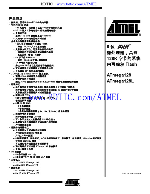
产品特点•高性能、低功耗的 AVR® 8位微处理器•先进的 RISC 结构–133条指令 – 大多数可以在一个时钟周期内完成–32 x 8 通用工作寄存器 + 外设控制寄存器–全静态工作–工作于16 MHz时性能高达16 MIPS–只需两个时钟周期的硬件乘法器•非易失性的程序和数据存储器–128K 字节的系统内可编程Flash寿命: 10,000次写/擦除周期–具有独立锁定位、可选择的启动代码区通过片内的启动程序实现系统内编程真正的读-修改-写操作–4K字节的EEPROM寿命: 100,000次写/擦除周期–4K 字节的内部SRAM–多达64K字节的优化的外部存储器空间–可以对锁定位进行编程以实现软件加密–可以通过SPI实现系统内编程•JTAG接口(与IEEE 1149.1标准兼容)–遵循JTAG标准的边界扫描功能–支持扩展的片内调试–通过JTAG接口实现对Flash, EEPROM, 熔丝位和锁定位的编程•外设特点–两个具有独立的预分频器和比较器功能的8位定时器/计数器–两个具有预分频器、比较功能和捕捉功能的16位定时器/计数器–具有独立预分频器的实时时钟计数器–两路8位PWM–6路分辨率可编程(2到16位)的PWM–输出比较调制器–8路10位ADC8个单端通道7个差分通道2个具有可编程增益(1x, 10x, 或200x)的差分通道–面向字节的两线接口–两个可编程的串行USART–可工作于主机/从机模式的SPI串行接口–具有独立片内振荡器的可编程看门狗定时器–片内模拟比较器•特殊的处理器特点–上电复位以及可编程的掉电检测–片内经过标定的RC振荡器–片内/片外中断源–6种睡眠模式: 空闲模式、ADC噪声抑制模式、省电模式、掉电模式、Standby模式以及扩展的Standby模式–可以通过软件进行选择的时钟频率–通过熔丝位可以选择ATmega103兼容模式–全局上拉禁止功能•I/O和封装–53个可编程I/O口线–64引脚TQFP与 64引脚 MLF封装•工作电压–2.7 - 5.5V ATmega128L–4.5 - 5.5V ATmega128•速度等级–0 - 8 MHz ATmega128L–0 - 16 MHz ATmega128微处理器,具有128K字节的系统BDTIC /ATMEL2ATmega1282467L–AVR–05/04引脚配置Figure 1. ATmega128的引脚综述ATmega128为基于AVR RISC 结构的8位低功耗CMOS 微处理器。
ATmega128 ATmega128L 介绍
ATmega128 是一种很复杂的微控制器 它的 I/O 地址取代了保留在AVR指令集中的 64 个 I/O地 址 为确保向后兼容 ATmega103 ATmega103上所有I/O的位置与ATmega128上的相同 很多附加的 I/O 地址被加到一个从$60到$FF的扩展外部I/O空间中(例如 在ATmega103 的内部 RAM 空间中) 这些地址只能用 LD/LDS/LDD 和 ST/STS/STD 指令访问 而不能用 IN 和 OUT 指令 内部 RAM 空 间的重定位对于ATmega103用户来说可能仍是一个问题 同样 如果代码使用绝对地址那么增加的中 断向量也是一个问题 要解决这些问题 可以通过编程一个熔丝M103C来选择 ATmega103 兼容模式 在这一模式下 不能使用扩展I/O空间中的程序 所以内部 RAM象ATmega103一样定位 同时 扩展 中断向量被去除 ATmega128 百分之百与 ATmega103引脚兼容 在PCB上可以替代ATmega103 应用笔记 “用ATmega128 替换 ATmega103” 中说明了用户在用ATmega128 替换 ATmega103时应 注意的事项 三 ATmega103 兼容模式
– 53个可编程的I/O 脚
– 64脚TQFP封装 (7) 工作电压
– 2.7 - 5.5V ATmega128L
– 4.5 - 5.5V ATmega128 (8) 速度等级
– 0 - 8 MHz ATmega128L
– 0 - 16 MHz ATmega128
AVR单片机外围电路设计

定时器/ 计数器
EEPROM
ATmega128的引脚图 (实际)
1256789012456789012345678901234 2233333444444444555555555566666 DDD NNN VCCVCC GGG AREF AVCC PC0(A8)PC1(A9) PC2(A10)PC3(A11)PC4(A12)PC5(A13)PC6(A14)PC7(A15) PA7(AD7)PA6(AD6)PA5(AD5)PA4(AD4)PA3(AD3)PA2(AD2)PA1(AD1)PA0(AD0) PF3(ADC3)PF2(ADC2)PF1(ADC1)PF0(ADC0) PF7(ADC7/TDI) PF5(ADC5/TMS)PF4(ADC4/TCK) PF6(ADC6/TDO) N E PPE0(RXD0/PDI)PE1(TXD0/PDO)PE2(XCK0/AIN0)PE3(OC3A/AIN1)PE4(OC3B/INT4)PE5(OC3C/INT5)PE6(T3/INT6)PE7(IC3/INT7)PB0(SS)PB1(SCK)PB2(MOSI)PB3(MISO)PB4(OC0)PB5(OC1A)PB6(OC1B)PB7(OC2/OC1C)TOSC2/PG3TOSC1/1PG4RESETXTAL2XTAL1PD0(SCL/INT0)PD1(SDA/INT1)PD2(RXD1/INT2)PD3(TXD1/INT3)PD4(IC1)PD5(XCK1)PD6(T1)PD7(T2)PG0(WR)PG1(RD)PG2(ALE) U14ATmega128L-8AI 012345678903456789012343 123456789 111111111122222222333334
0(输出)
共阴
atmega128L串口通信详解
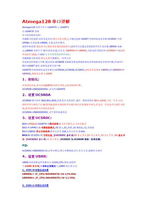
/***********************************************************************
void uart0_init(void00; //关闭 UART00 //不使用倍速发送(异步) //数据位为 8 位 //异步正常情况下的计算公式 //接收使能和发送使能
while (*s) { putchar0(*s); s++; } putchar0(0x0a);//回车换行 //putchar0(0x0d); } /*********************************************************************** ***** 函数功能:主程序 入口参数: 出口参数: ************************************************************************ ****/ void main(void) { unsigned char i; uart0_init();//UART0 初始化 puts0("HELLO!"); while(1) { puts0("test ok!"); } }
eg:
UCSR0C=0B00000110 //异步模式,禁止奇偶校验,停止位为 1 位,数据位为 8 位
4、设置 UBRR:
UBRR 的设置和这些参数有关:U2X0,CPU 频率,波特率 当 U2X0 为 0 时,即异步正常模式 异步正常模式下 异步正常模式 ,UBRR 的计算公式: 1、U2X=0 时的公式计算 UBRR0L= (F_CPU/BAUDRATE/16-1)%256; UBRR0H= (F_CPU/BAUDRATE/16-1)/256; 2、U2X=1 时的公式计算
ATmega128单片机的系统结构
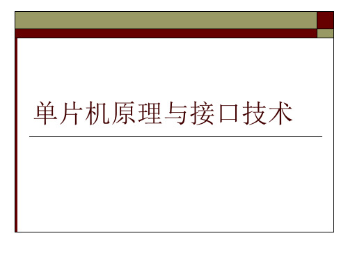
这个时钟也可以作为系统时钟,只要对熔 丝位CKSEL进行编程即可。选择这个时钟 之后就无需外部器件了。
3、系统时钟及其选项
外部时钟
为了从外部时钟源驱动芯 片, XTAL1 必须如图所示 的进行连接。同时,熔丝 位CKSEL必须编程为 “0000”。
1.1 AVR CPU内核的结构 1.2 状态寄存器 1.3 通用寄存器结构 1.4 X、Y、Z寄存器 1.5 堆栈指针 1.6 复位和中断处理
1.1 AVR CPU内核的结构图
AVR 采用了Harvard 结构, 具有独立的数据和程序总线。 程序存储器的指令通过一级流 水线运行。
1.2 状态寄存器
ADC 时钟 clkADC ADC具有专门的时钟。这样可 以在ADC工作的时候停止CPU和I/O时钟以降低 数字电路产生的噪声,从而提高ADC 转换精度。
3、系统时钟及其选项
时钟源 ATmega128有如下几种通过熔丝位选择的
时钟源。时钟输入到AVR 时钟发生器,并 通往其他合适模块。
3、系统时钟及其选项
电路无论何时,只要Vcc低于检测电平Vpot时,器 件进入复位状态。
4、系统控制和复位
2.外部复位 外部复位是由外加在RESET引脚上的低电平将产生 的。当RESET引脚被拉低于Vrst的时间大于1.5µs时 既触发复位过程
4、系统控制和复位
3.掉电检测(BOD)复位 ATmega128片内的BOD( Brown-out Detection)电源检测电路,用于在 系统运行时对系统电压VCC的检测,并同一个固定的阈值电压相比较。 BOD检测阈值电压可以通过BODLEVEL熔丝位设定为2.7V或4.0V。 BOD检测阈值电压有迟滞效应,以避免系统电源的尖峰毛刺误触发BOD 检测器。阈值电平的迟滞效应可以理解为:上阈值电压VBOT+ = VBOT + VHYST/2,下阈值电压VBOT- = VBOT - VHYST/2。
