2SK1538-芯片资料介绍
HJ1538中文资料

Page No. : 1/3HJ1538PNP EPITAXIAL PLANAR TRANSISTORDescriptionHigh-definition CRT display video output, wide-band amp.Features• High fT: fT=400MHz• High breakdown voltage: VCEO=-120Vmin• Small reverse transfer capacitance and excellent HF responseAbsolute Maximum Ratings (Ta=25°C)• Maximum TemperaturesStorage Temperature............................................................................................ -55 ~ +150 °C Junction Temperature.................................................................................................... +150 °C • Maximum Power DissipationTotal Power Dissipation (Tc=25°C)................................................................................... 1.3 W • Maximum Voltages and CurrentsBVCBO Collector to Base Voltage................................................................................... -120 V BVCEO Collector to Emitter Voltage................................................................................ -120 V BVEBO Emitter to Base Voltage.......................................................................................... -3 V IC Collector Current...................................................................................................... -100 mA IC Peak Collector Current............................................................................................. -100 mA Characteristics (Ta=25°C)Symbol Min.Typ.Max.Unit Test ConditionsBVCBO-120--V IC=-10uA, IE=0BVCEO-120--V IC=-1mA, IB=0BVEBO-3--V IE=-100uA, IC=0ICBO---100nA VCB=-80VIEBO---100nA VEB=-2V*VCE(sat)---1V IC=-30mA, IB=-3mA*VBE(sat)---1V IC=-30mA, IB=-3mA*hFE160160320VCE=-10V, IC=-10mA*hFE240--VCE=-10V, IC=-100mAfT400--MHz VCE=-10V, IC=-50mACob 2.8--pF VCB=-30V, f=1MHz*Pulse Test : Pulse Width ≤380us, Duty Cycle≤2% Classification Of hFE1Rank D E FRange60-120100-200160-320Page No. : 2/3 Characteristics CurvePage No. : 3/3*:TypicalInches Millimeters Inches Millimeters DIM Min.Max.Min.Max.DIM Min.Max.Min.Max.A 0.01770.02170.450.55G0.08660.1102 2.20 2.80B 0.06500.0768 1.65 1.95H -*0.0906-*2.30C 0.03540.05910.90 1.50I -0.0354-0.90D 0.01770.02360.450.60J -0.0315-0.80E 0.25200.2677 6.40 6.80K 0.20470.2165 5.20 5.50F0.21250.2283 5.40 5.80L0.05510.0630 1.40 1.60Notes : 1.Dimension and tolerance based on our Spec. dated May. 05,1996.2.Controlling dimension : millimeters.3.Maximum lead thickness includes lead finish thickness, and minimum lead thickness is the minimum thickness of base material.4.If there is any question with packing specification or packing method, please contact your local HSMC sales office.Material :• Lead : 42 Alloy ; solder plating• Mold Compound : Epoxy resin family, flammability solid burning class:UL94V-0Important Notice:• All rights are reserved. Reproduction in whole or in part is prohibited without the prior written approval of HSMC.• HSMC reserves the right to make changes to its products without notice.• HSMC semiconductor products are not warranted to be suitable for use in Life-Support Applications, or systems.• HSMC assumes no liability for any consequence of customer product design, infringement of patents, or application assistance.Head Office And Factory :• Head Office (Hi-Sincerity Microelectronics Corp.) : 10F.,No. 61, Sec. 2, Chung-Shan N. Rd. Taipei Taiwan R.O.C.Tel : 886-2-25212056 Fax : 886-2-25632712, 25368454• Factory 1 : No. 38, Kuang Fu S. Rd., Fu-Kou Hsin-Chu Industrial Park Hsin-Chu Taiwan. R.O.C Tel : 886-3-5983621~5 Fax : 886-3-5982931• Factory 2 : No. 17-1, Ta-Tung Rd., Fu-Kou Hsin-Chu Industrial Park Hsin-Chu Taiwan. R.O.C Tel : 886-3-5977061 Fax : 886-3-5979220。
2SK3078A资料
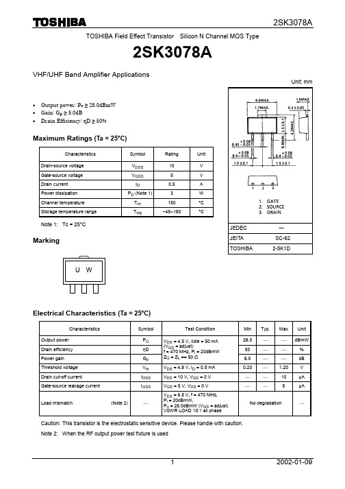
TOSHIBA Field Effect Transistor Silicon N Channel MOS Type2SK3078AVHF/UHF Band Amplifier Applications· Output power: P o ≥ 28.0dBmW · Gain: G p ≥ 8.0dB· Drain Efficiency: ηD ≥ 50%Maximum Ratings (Ta = 25°C)Characteristics Symbol Rating UnitDrain-source voltage V DSS10 VGate-source voltage V GSS 5 V Drain current I D 0.5 A Power dissipation P D (Note 1)3WChannel temperature T ch 150 °C Storage temperature rangeT stg−45~150 °CNote 1: Tc = 25°CMarkingElectrical Characteristics (Ta = 25°C)Characteristics Symbol Test Condition Min Typ. Max UnitOutput power P O 28.0 ¾ ¾ dBmW Drain efficiency ηD 50 ¾ ¾ % Power gain G p V DS = 4.5 V, Iidle = 50 mA(V GS = adjust)f = 470 MHz, P i = 20dBmWZ G = Z L == 50 Ω 8.0 ¾ ¾ dB Threshold voltage V th V DS = 4.8 V, I D = 0.5 mA 0.20 ¾ 1.20VDrain cut-off current I DSS V DS = 10 V, V GS = 0 V ¾ ¾ 10 µA Gate-source leakage currentI GSSV GS = 5 V, V DS = 0 V¾¾ 5 µALoad mismatch (Note 2)¾V DS = 6.5 V, f = 470 MHz, P i = 20dBmW,P o = 28.0dBmW (V GS = adjust) VSWR LOAD 10:1 all phaseNo degradation ¾Caution: This transistor is the electrostatic sensitive device. Please handle with caution. Note 2: When the RF output power test fixture is usedUnit: mmJEDEC―JEITA SC-62 TOSHIBA 2-5K1DU WPF Output Power Test FixtureGS DSL1: f 0.6, 5.5ID, 5T L2: f 0.6, 5.5ID, 7TLine: 2 mmP i – P o , G p , EffIidle – G p , EffP i – P oP i – IddVdd – G p , EffP i – P oP i (dBmW)Iidle (mA)P i (dBmW)P i (dBmW)Vdd (V)P i (dBmW)G p (d B m W )P o (d B m W )D r a i n c u r r e n t (m A )P o (d B m W )E f f (%) P o (d B m W )G p (d B )E f f (%)10050Idd (%)255 15 20 10 03020100 302010 082 46Eff3020Vdd Vdd Vdd VddCaution: These are typical curves and devices are not necessarily guaranteed at these curves.P i – IddP i (dBmW)I d d (m A )301020· TOSHIBA is continually working to improve the quality and reliability of its products. Nevertheless, semiconductor devices in general can malfunction or fail due to their inherent electrical sensitivity and vulnerability to physical stress. It is the responsibility of the buyer, when utilizing TOSHIBA products, to comply with the standards of safety in making a safe design for the entire system, and to avoid situations in which a malfunction or failure of such TOSHIBA products could cause loss of human life, bodily injury or damage to property.In developing your designs, please ensure that TOSHIBA products are used within specified operating ranges as set forth in the most recent TOSHIBA products specifications. Also, please keep in mind the precautions and conditions set forth in the “Handling Guide for Semiconductor Devices,” or “TOSHIBA Semiconductor Reliability Handbook” etc.. · The TOSHIBA products listed in this document are intended for usage in general electronics applications (computer, personal equipment, office equipment, measuring equipment, industrial robotics, domestic appliances, etc.). These TOSHIBA products are neither intended nor warranted for usage in equipment that requires extraordinarily high quality and/or reliability or a malfunction or failure of which may cause loss of human life or bodily injury (“Unintended Usage”). Unintended Usage include atomic energy control instruments, airplane or spaceship instruments, transportation instruments, traffic signal instruments, combustion control instruments, medical instruments, all types of safety devices, etc.. Unintended Usage of TOSHIBA products listed in this document shall be made at the customer’s own risk. · The information contained herein is presented only as a guide for the applications of our products. No responsibility is assumed by TOSHIBA CORPORATION for any infringements of intellectual property or other rights of the third parties which may result from its use. No license is granted by implication or otherwise under any intellectual property or other rights of TOSHIBA CORPORATION or others. · The information contained herein is subject to change without notice.000707EAARESTRICTIONS ON PRODUCT USE。
2SD1538A资料

123Request for your special attention and precautions in using the technical information andsemiconductors described in this book(1)If any of the products or technical information described in this book is to be exported or provided to non-residents, the laws andregulations of the exporting country, especially, those with regard to security export control, must be observed. (2)The technical information described in this book is intended only to show the main characteristics and application circuit examplesof the products, and no license is granted under any intellectual property right or other right owned by our company or any other company. Therefore, no responsibility is assumed by our company as to the infringement upon any such right owned by any other company which may arise as a result of the use of technical information described in this book.(3)The products described in this book are intended to be used for standard applications or general electronic equipment (such as officeequipment, communications equipment, measuring instruments and household appliances). Consult our sales staff in advance for information on the following applications:– Special applications (such as for airplanes, aerospace, automobiles, traffic control equipment, combustion equipment, life support systems and safety devices) in which exceptional quality and reliability are required, or if the failure or malfunction of the prod-ucts may directly jeopardize life or harm the human body.– Any applications other than the standard applications intended.(4)The products and product specifications described in this book are subject to change without notice for modification and/or im-provement. At the final stage of your design, purchasing, or use of the products, therefore, ask for the most up-to-date Product Standards in advance to make sure that the latest specifications satisfy your requirements. (5)When designing your equipment, comply with the range of absolute maximum rating and the guaranteed operating conditions(operating power supply voltage and operating environment etc.). Especially, please be careful not to exceed the range of absolute maximum rating on the transient state, such as power-on, power-off and mode-switching. Otherwise, we will not be liable for any defect which may arise later in your equipment.Even when the products are used within the guaranteed values, take into the consideration of incidence of break down and failure mode, possible to occur to semiconductor products. Measures on the systems such as redundant design, arresting the spread of fire or preventing glitch are recommended in order to prevent physical injury, fire, social damages, for example, by using the products.(6)Comply with the instructions for use in order to prevent breakdown and characteristics change due to external factors (ESD, EOS,thermal stress and mechanical stress) at the time of handling, mounting or at customer's process. When using products for which damp-proof packing is required, satisfy the conditions, such as shelf life and the elapsed time since first opening the packages.(7)This book may be not reprinted or reproduced whether wholly or partially, without the prior written permission of MatsushitaElectric Industrial Co., Ltd.M a i n t e n a n D i s c o n t i n u eP le a s ev i s it f o l l o w i n g U R L a b o u t l a t e s t i n fo r mh t t p ://p a n a s o n i c .n e t /s c /e n。
AP1538中文资料

FeaturesGeneral DescriptionAP1538 consists of step-down switching regulator with PWM control. These devices include a reference voltage source, oscillation circuit, error amplifier, internal PMOS.• Input voltage : 3.6V to 18V • Output voltage : 0.8V to V CC • Output current : up to 3AAP1538 provides low-ripple power, high efficiency, and excellent transient characteristics. The PWM control circuit is able to vary the duty ratio linearly from 0 up to 99%. This converter also contains an error amplifier circuit as well as a soft-start circuit that prevents overshoot at startup. An enable function, an over current protect function and a short circuit protect function are built inside, and when OCP or SCP happens, the operation frequency will be reduced from 300KHz to 50KHz. Also, an internal compensation block is built in to minimum external component count.• Duty ratio: 0% to 99% PWM control • Oscillation frequency: 300KHz typical• Soft-start like, Current limit and Enable function • Thermal Shutdown function• Built-in internal SW P-channel MOS• SOP-8L and SOP-8L-DEP: Available in “Green” Molding Compound (No Br, Sb)•Lead Free Finish / RoHS Compliant (Note 1)With the addition of an internal P-channel Power MOS, a coil, capacitors, and a diode connected externally, these ICs can function as step-down switching regulators. They serve as ideal power supply units for portable devices when coupled with the SOP-8L and SOP-8L-DEP mini-packages, providing such outstanding features as low current consumption. Since this converter can accommodate an input voltage up to 18V, it is also suitable for the operation via an AC adapter.Applications• PC Motherboard • LCD Monitor • Graphic Card• DVD-Video Player • Telecom Equipment • ADSL Modem• Printer and other Peripheral Equipment •Microprocessor core supplyOrdering InformationAP 1538 XXX G - XPackage Packing S : SOP-8LLead Free U : Tube13 : Tape & ReelG : GreenSDP : SOP-8L-DEPTube 13” Tape and ReelDevice PackageCodePackaging (Note 2)Quantity Part Number Suffix Quantity Part NumberSuffixAP1538SG-U S SOP-8L 100 -U NA NA AP1538SG-13 S SOP-8L NA NA 2500/Tape & Reel -13 AP1538SDPG-U SDP SOP-8L-DEP 100 -U NA NA AP1538SDPG-13 SDP SOP-8L-DEP NA NA 2500/Tape & Reel -13Notes: 1. EU Directive 2002/95/EC (RoHS). All applicable RoHS exemptions applied, see EU Directive 2002/95/EC Annex Notes .2. Pad layout as shown on Diodes Inc. suggested pad layout document AP02001, which can be found on our website at/datasheets/ap02001.pdf .Pin Assignments(1) SOP-8L (2) SOP-8L-DEP (Dual Exposed Pads)FBOutputOCSETOutputENVssVssV CC( Top View )FBOutputOCSETOutputENVssVssV CC( Top View )Notes: 3. Exposed pad 1 is connected to VSS and exposed pad 2 is connected to Output. The board layout for exposed pads needs to be considered to avoid short circuit.Pin DescriptionsPin Name Pin No. DescriptionFB 1FeedbackpinEN 2Power-off pinH: Normal operation(Step-down operation)L: Step-down operation stopped(All circuits deactivated)OCSET 3 Add an external resistor to set max output currentV CC 4 IC power supply pinOutput 5,6Switch Pin. Connect external inductor/diode here. Minimize tracearea at this pin to reduce EMIV SS7, 8 GND PinBlock DiagramVccAbsolute Maximum RatingsSymbol ParameterRating Unit ESD HBM Human Body Model ESD Protection7 KV ESD MM Machine Model ESD Protection 450V V CC V CC Pin Voltage V SS - 0.3 to V SS + 20VV FB Feedback Pin Voltage V SS - 0.3 to V CC V V EN EN Pin Voltage V SS - 0.3 to V CC V V OUT Switch Pin Voltage V SS - 0.3 to V CC V P D Power DissipationInternally limited mWT J Operating Junction Temperature Range -40 to +125 o C T ST Storage Temperature Range-65 to +150oCCaution: The absolute maximum ratings are rated values exceeding which the product could suffer physical damage.These values must therefore not be exceeded under any conditions.Recommended Operating ConditionsSymbol Parameter MinMax Unit V IN Input Voltage (Note 4) 3.618VI OUT Output Current 0 3 A T A Operating Ambient Temperature-20+85o CNotes: 4. For the operations in low input voltage, AP1538 can tolerate down to 3.6V but max output current loading will be less than 3A. For nominalapplications in such low input voltage range, especially lower than 4V, a higher ROCSET with larger heat sink is recommended.Electrical Characteristics(V IN = 12V, T A = 25°C, unless otherwise specified) Symbol Parameter Conditions Min Typ. Max Unit V FB Feedback Voltage I OUT = 0.1A 0.784 0.8 0.816V I FB Feedback Bias Current I OUT = 0.1A- 0.1 0.5 µA I SHDN Current Consumption DuringPower Off V EN = 0V- 10 - µA ∆V OUT/ V INLine RegulationV IN = 5V~18V-12%∆V OUT/ V OUTLoad Regulation I OUT = 0.1 to 3A - 0.2 0.5 %f OSC Oscillation Frequency Measure waveform at SW pin 240 300 400 KHzf OSC1 Frequency of Current Limit orShort Circuit Protection Measure waveform at SW pin - 50 - KHzV IH Evaluate oscillation at SW pin 2.0 - -V IL EN Pin Input Voltage Evaluate oscillation stop at SW pin - - 0.8 V I SH EN Pin High - 20 - µAI SL EN Pin Input Leakage Current EN Pin Low - -10 - µA I OCSET OCSET Pin Bias Current -- 75 90 105 µAV IN =5V, V FB =0V - 110 -R DS(ON) Internal MOSFET R DS(ON)V IN =12V, V FB =0V -70 - m Ω EFFI EfficiencyV IN =12V, V OUT = 5VI OUT =3A- 92 - % T SHDN Thermal shutdown threshold - 150 - °C T HYS Thermal shutdown hysteresis - 55 - °CSOP-8L (Note 5) 24 θJC Thermal Resistance Junction-to-Case SOP-8L-DEP (Note 5) - 26- oC/WNotes: 5. Test condition for SOP-8L and SOP-8L-DEP: Devices mounted on 2oz copper, minimum recommended pad layout on top & bottom layer with thermal vias, double sided FR-4 PCB.Typical Application CircuitVV OUT = V FB x (1+R A /R B )R B = 0.7K~5K ohmNotes: 6. Suggested DIODES Power Schottky P/N: B340 series or PDS340.7. Suggested C OUT for V OUT < 1V; 680μF.8. Typical feedback compensation (Cc): 5600pF.Typical Performance CharacteristicsTypical Performance Characteristics (Continued)V OUT Ripple(V IN = 12V, V OUT = 3.3V, I OUT = 0.1A)V OUT Ripple(V IN = 12V, V OUT = 3.3V, I OUT = 3.0A)Load Transient Response(V IN = 12V, V OUT = 3.3V, I OUT = 0.1~3A)Test CircuitFunctional DescriptionPWM ControlThe AP1538 is a DC/DC converter that employs pulse width modulation (PWM) scheme. Its pulse width varies in the range of 0% to 99%, based on the output current loading. The output ripple voltage caused by the PWM high frequency switching can easily be reduced through an output filter. Therefore, this converter provides a low ripple output supply over a broad range of input voltage & output current loadingUnder Voltage LockoutThe under voltage lockout circuit of the AP1538 assures that the high-side MOSFET driver remains in the off state whenever the supply voltage drops below 3.3V. Normal operation resumes once V CC rises above 3.5V.Current Limit ProtectionThe current limit threshold is set by external resistor R OCSET connected from V CC supply to OCSET pin. The internal sink current I OCSET (90uA typical) across this resistor sets the voltage at OCSET pin. When the PWM voltage is less than the voltage at OCSET, an over-current condition is triggered.The current limit threshold is given by the following equation:R I R I OCSET OCSET DS(ON)PEAK ×=×2I)(I I (MAX) OUT PEAKΔ+>where,INOUTS OUT V V L F V V I ××−=ΔINI PEAK is the output peak current; R DS (ON) is the MOSFET ON resistance; F S is the PWM frequency (300KHz typical). Also, the inductor value will affect the ripple current ΔI.The above equation is recommended for input voltage range of 5V to 18V. For input voltage lower than 5V or ambient temperature over 100°C, higher R OCSET is recommended.The recommended minimum R OCSET value is summarized below:V IN (V) V OUT(V) 5V 12V 18V 0.8 4.7K 3.0K 3.3K 1.0 5.6K 3.0K 3.9K 1.2 5.6K 3.0K 3.9K 1.8 5.6K 3.0K 3.9K 2.5 5.6K 3.0K 3.9K 3.3 5.6K 3.0K 3.9K 5.0 N/A 3.0K 4.7KInductor SelectionFor most designs, the operates with inductors of 22µH to 33µH. The inductor value can be derived from the following equation:()oscL ONOUT IN f I T V V L ×Δ×−=2Where ΔI L is inductor Ripple Current. Large value inductors lower ripple current and small value inductors result in high ripple current. Choose inductor ripple current approximately 15% of the maximum load current 3A, ∆I L =0.45A. The DC current rating of the inductor should be at least equal to the maximum load current plus half the ripple current to prevent core saturation (3A+0.225A).Input Capacitor SelectionThis capacitor should be located close to the IC using short leads and the voltage rating should be approximately 1.5 times the maximum input voltage. The RMS current rating requirement for the input capacitor of a buck regulator is approximately 1⁄2 the DC load current. A low ESR input capacitor sized for maximum RMS current must be used. A 470µF low ESR capacitor for most applications is sufficient.Output Capacitor SelectionThe output capacitor is required to filter the output voltage and provides regulator loop stability. The important capacitor parameters are the 100KHz Equivalent Series Resistance (ESR), the RMS ripples current rating, voltage rating and capacitance value. For the output capacitor, the ESR value is the most important parameter. The output ripple can be calculated from the following formula.ESR I V L RIPPLE ×Δ=The bulk capacitor’s ESR will determine the output ripple voltage and the initial voltage drop after a high slew-rate transient.An aluminum electrolytic capacitor's ESR value is related to the capacitance and its voltage rating. In most case, higher voltage electrolytic capacitors have lower ESR values. Most of the time, capacitors with much higher voltage ratings may be needed to provide the low ESR values required for low output ripple voltage.PCB Layout GuideIf you need low T C & T J or large PD (Power Dissipation), The dual SW pins(5& 6) and Vss pins(7& 8)on the SOP-8L package are internally connected to die pad, The evaluation board should be allowed for maximum copper area at output (SW) pins.1. Connect FB circuits (R 1, R 2, C 1) as closely as possible and keep away from inductor flux for pure V FB .2. Connect C3 to Vcc and Vss pin as closely as possible to get good power filter effect.3. Connect R4 to Vcc and OCSET pin as closely as possible.4. Connect ground side of the C2 & D1 & C4 as closely as possible and use ground plane for best performance.Functional Description (Continued)Functional Description (Continued)V OUTVINFigure: Layout numbering comparison.Marking Information(1) SOP-8L( Top View )SOP-8LAP1538Logo Part No Year : "07" =2007 "08" =2008Xth week:01~52~G : Green(2) SOP-8L-DEP( Top View )SOP-8L-DEPLogo Part No Internal code Year : "07" =2007 "08" =2008Xth week:01~52~G : GreenE : SOP-8L-DEPPackage Information ( All Dimensions in mm ) (1) SOP-8LDetail "A"(Unit: mm)(2) SOP-8L-DEPBottom viewIMPORTANT NOTICEDiodes Incorporated and its subsidiaries reserve the right to make modifications, enhancements, improvements, corrections or other changes without further notice to any product herein. Diodes Incorporated does not assume any liability arising out of the application or use of any product described herein; neither does it convey any license under its patent rights, nor the rights of others. The user of products in such applications shall assume all risks of such use and will agree to hold Diodes Incorporated and all the companies whose products are represented on our website, harmless against all damages.LIFE SUPPORTDiodes Incorporated products are not authorized for use as critical components in life support devices or systems without the expressed written approval of the President of Diodes Incorporated.。
主流无线芯片汇总及特点解析
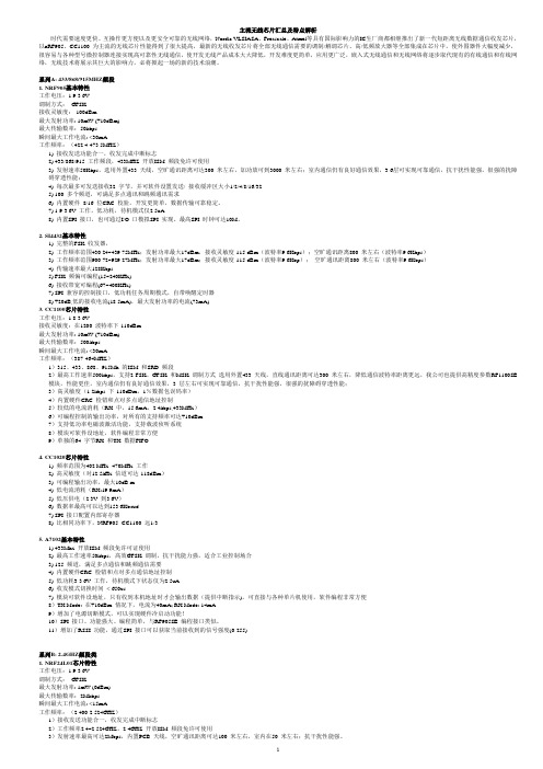
主流无线芯片汇总及特点解析时代需要速度更快、互操作更方便以及更安全可靠的无线网络,Nordic VLSIASA、Freascale、Atmel等具有国际影响力的IC生厂商都相继推出了新一代短距离无线数据通信收发芯片,以nRF905、CC1100 为主流的无线芯片性能得到了很大提高,最新的无线收发芯片将全部无线通信需要的调制/解调芯片、高/低频放大器等全部集成在芯片中,使外围器件大幅度减少,很容易与各种型号微控制器连接实现高可靠性无线通信,使开发无线产品成本大大降低,开发难度更简单,应用更广泛,嵌入式无线通信和无线网络将逐步取代现有的有线通信和有线网络,无线技术将展示其巨大的影响力,必将掀起一场的新的技术浪潮。
系列A: 433/868/915MHZ频段1. NRF905基本特性工作电压:1.9-3.6V调制方式:GFSK接收灵敏度:-100dBm最大发射功率: 10mW (+10dBm)最大传输数率:50kbps瞬间最大工作电流: <30mA工作频率:(422.4-473.5MHZ)1) 接收发送功能合一,收发完成中断标志2) 433/868/915 工作频段,433MHZ 开放ISM 频段免许可使用3) 发射速率50Kbps,选用外置433 天线,空旷通讯距离可达300 米左右,加功放可到3000 米左右;室内通信仍有良好通信效果,3-6层可实现可靠通信,抗干扰性能强,很强的扰障碍穿透性能;4) 每次最多可发送接收32 字节,并可软件设置发送/ 接收缓冲区大小1/2/4/8/16/325) 100 多个频道,可满足多点通讯和跳频通讯需求6) 内置硬件8/16 位CRC 校验,开发更简单,数据传输可靠稳定。
7) 1.9-3.6V 工作,低功耗,待机模式仅2.5uA.8) 内置SPI 接口,也可通过I/O 口模拟SPI 实现。
最高SPI 时钟可达10M。
2. SI4432基本特性1) 完整的FSK 收发器,2) 工作频率范围430.24~439.75MHz;发射功率最大17dBm,接收灵敏度-115 dBm(波特率9.6Kbps);空旷通讯距离800 米左右(波特率9.6Kbps)3) 工作频率范围900.72~929.27MHz;发射功率最大17dBm;接收灵敏度-115 dBm(波特率9.6Kbp);空旷通讯距离800 米左右(波特率9.6Kbps)4) 传输速率最大128Kbps5) FSK 频偏可编程(15~240KHz)6) 接收带宽可编程(67~400KHz)7) SPI 兼容的控制接口,低功耗任务周期模式,自带唤醒定时器8) +20dB,低的接收电流(18.5mA),最大发射功率的电流(73mA)3. CC1100芯片特性工作电压:1.8-3.6V接收灵敏度:在1200 波特率下-110dBm最大发射功率: 10mW (+10dBm)最大传输数率:500kbps瞬间最大工作电流: <30mA工作频率:(387-464MHZ)1)315、433、868、915Mh 的ISM 和SRD 频段2)最高工作速率500kbps,支持2-FSK、GFSK 和MSK 调制方式选用外置433 天线,直线通讯距离可达300 米左右,降低通信波特率距离更远,我公司也提供高精度参数RF1100SE 模块,性能更佳,室内通信仍有良好通信效果,3 层左右可实现可靠通信,抗干扰性能强,很强的扰障碍穿透性能;3)高灵敏度(1.2kbps 下-110dDm,1%数据包误码率)4)内置硬件CRC 检错和点对多点通信地址控制5)较低的电流消耗(RX 中,15.6mA,2.4kbps,433MHz)6)可编程控制的输出功率,对所有的支持频率可达+10dBm7)支持低功率电磁波激活功能,支持载波侦听系统8)模块可软件设地址,软件编程非常方便9)单独的64 字节RX 和TX 数据FIFO4. CC1020芯片特性1) 频率范围为402 MHz -470MHz 工作2) 高灵敏度(对12.5kHz 信道可达-118dBm)3) 可编程输出功率,最大10dB m4) 低电流消耗(RX:19.9mA)5) 低压供电(2.3V 到3.6V)6) 数据率最高可以达到153.6Kbaud7) SPI 接口配置内部寄存器8) 比相同功率下,NRF905- CC1100 远1/35. A7102基本特性1) 433Mhz 开放ISM 频段免许可证使用2) 最高工作速率50kbps,高效GFSK 调制,抗干扰能力强,适合工业控制场合3) 125 频道,满足多点通信和跳频通信需要4) 内置硬件CRC 检错和点对多点通信地址控制5) 低功耗3-3.6V 工作,待机模式下状态仅为2.5uA6) 收发模式切换时间< 650us7) 模块可软件设地址,只有收到本机地址时才会输出数据(提供中断指示),可直接与各种单片机使用,软件编程非常方便8)TX Mode: 在+10dBm 情况下,电流为40mA; RX Mode: 14mA9)增加了电源切断模式,可以实现硬件冷启动功能!10)SPI 接口、功能强大、编程简单,与RF905SE 编程接口类似。
各厂家中九接收机芯片IC资料大全(目前最完整的)部分附针脚定义

各厂家中九接收机芯片IC资料大全(目前最完整的)部分附针脚定义最新刷机资料点下面的链接最新刷机资料1最新刷机资料24月3日BIN教程工具集中帖刷机教程大全刷机工具大全2.10-3.2刷机bin大全3月3日后刷机bin大全各厂家中九接收机顶盒芯片IC资料大全(目前最完整的),部分附针脚定义。
方便大家速查。
可使用CTRL+F,然后输入相关数据进行速查,或者也可以下载附件。
品牌产品型号芯片配置海尔2晶10芯IC:HI2023E+1108+5812海尔高清OST-666 2晶6芯IC:M88VS2000+241674K.1+M88TS2020海尔高清OST-666 3晶12芯IC:High032E+His121+M88TS2020海尔3晶10芯(9针接口)IC:HI2023E+1108+5812+ESMTM12L64164A-GNR1T80AB 海尔高清OST-666 2晶6芯IC:Hi2023E+3160+TS2020欧视达ABS-209B 3晶10芯IC:GX3001+GX1121+LW37 欧视达ABS-209B 3晶11芯IC:GX3001+5037+8211欧视达ABS-309B 3晶11芯IC:GX3001+GX1121+MGCE5037欧视达AS-900S 1晶11芯IC:GX6121+25L80+LW37城市之宝BEX868 Y32S-93AT 2晶10芯IC:HTV903F+A VL1108+TS2020通达Y35S-8BAT/Y35S-8CAT 2晶10芯IC:HTV903+A VL1108+5812通达Y30S-01BT 2晶12芯IC:HTV903+A VL1108+2020 皇朝HSR-268 10芯IC:Hi2023+A VL1108+5812小霸王TDX-668E ABS-S1 1晶6芯IC:Hi2023+Hi3102+FT8211+HT1117天地星小霸王TDX-328B 1晶10芯IC:ALi M3328F+5810天地星小霸王TDX-668A (9针接口)IC:HI2023+1108+夏普头天地星小霸王TDX-668B 2晶振IC:HTV903+A VL1108EGA+RDA5812+25L8005天地星小霸王(三星数码王)TDX-668B 单晶6芯.针脚定义①-TXD ②-RXD ③VCC ④-GND ⑤-BL IC:Hi2023E+RDA5812+A VL1108E+MXT8211a+25L8005天地星(原大盒中星九号)3晶IC:Hi2023+1108+5037天地星TDX-668B 2晶10芯IC:Hi2023+A VL1108+5812天地星小霸王TDX-668C 2晶6芯IC:HTV903+A VL1108EGA+RDK5812+25F80小霸王TDX-328B 1晶10芯IC:ALi M3328F+5810小霸王TDX-668B 6芯IC:Hi2023+RDA5812+A VL1108E 小霸王TDX-668B 2晶6芯IC:HTV903+1108+5812小霸王TDX-668E 1晶6芯IC:Hi2023EC+Hi3121+5812 小霸王TDX-668E 2晶6芯IC:HTV903+1108+5812小霰王XC-B298 1晶12芯IC:HTV903-RDA5812-A VL1108 小霸王ABS-1388 2晶10芯针脚定义①-GND ②-RXD ③-TXD ④VCC小霸王ABS-1688 2晶10芯针脚定义①-GND ②-RXD ③-TXD ④VCC IC:Hi2023EC+Hi3122E+5812小霸王GF902 IC:A VL1118a+A V2020+EN25F80索尼高清ABS-S 258 2晶10芯针脚定义①-GND ②-RXD ③-TXD ④VCC IC:Hi2023EC+Hi3122E+5812索尼高清ABS-S 258 2晶10芯针脚定义①-GND ②-RXD ③-TXD ④VCC IC:Hi3102E+Hi2023EC+A V2020太阳红TYH-279ABS/289ABS/299ABS 2晶10芯针脚定义①-GND ②-RXD ③-TXD ④VCC松下科技星TDX-668B1/松下科技星-668EIC:Hi3102E+Hi2023EC+5812松下科技星TDX-668B 2晶6芯IC:HTV903FH42+A VL1108EGA+RGK5812松下科技星668B 2晶6芯Hi2023(E0908)+EVl1108EG2+5812松下科技星-668C 2晶6芯针脚定义①-RX .②-TX .③-GND .④VCC. ⑤-BLIC:A VL1108EG+HTV903F+5812松下科技星668E 2晶6芯IC:HV903+A VL1108E+5812松下科技星/海尔数码/海信数码单双晶6芯IC:Hi2023E+Hi3102(Hi3121)+5812松下科技星TDX-668B 2晶6芯针脚定义①-RXD .②-TXD .③-GND .④VCC. ⑤-BLIC:Hi2023+A VL1108+5812+25L8005松下高清SX168 3晶6芯IC:HTV903F+A VL1108+A V2020 松下数码王P-269A 2晶6芯IC:Hi2023E+Hi3122+A V2020 松下高清OST168 2晶10芯IC:Hi2023E+Hi3121+A V2020 松下科技PS-228 11芯IC:Hi2023+Hi3122+5812松下科技PS-228 2晶6芯IC:M88VS2000+M88TS2020+ES261474K松下科技PS-228 1晶12芯N88VS2000+ES261344K+M88TS2020高频头+T25P80+S163816STS松下科技PS-228 2晶IC:HTV903+1108+2020松下科技PS-228 2晶10芯IC:GX3001+GX1211+5812松下数码王OST-266 10芯(4针)针脚定义①-GND ②-RXD ③-TXD ④VCCIC:Hi2023E+Hi3106+2020松下数码王OST-266 2晶6芯IC:M88VS2000+M88TS2020+261414k+25F80松下数码王OST-266 2晶6芯IC:Hi2023E+Hi3102E+M88TS2020+MXT8211松下高清OST-466 2晶10芯IC:Hi2023e+Hi3121+MBBTS2020+MBDA80CG松下科技星3晶6芯IC:Hi2023+A VL1108+WGCE5037松下科技星.海尔数码.海信数码单双晶+6芯IC:Hi2023E+Hi3102(3121)+5812中星科技单晶14芯IC:Hi2023E+1108+5812+25L8单晶14芯中星科技ZG-N02 12芯IC:GX3001+A V2020中星科技2晶10芯针脚定义①-GND ②-RXD ③-TXD ④VCCIC:Hi2023EC+Hi3102E+5812+M12L64164A中兴科技ABS-S323 2晶10芯IC:Hi2023EC+HI3102E+5812+M12L64164A村村通ABS-S323- 2晶10芯针脚定义①-GND ②-RXD ③-TXD ④VCCIC:Hi2023EC+Hi3122E+5812村村通2晶6芯IC:HN4+0001+5812村村通ZL5188 1晶13芯IC:HTV903+1108+SHARP高频头村村通ZL-5188A 2晶11芯IC:HTV903+A VL1108+RDK5812村村通ZL-5188B 2晶13芯IC:HTV903+A VL1108+RDK5812 村村通ZL-5188B 2晶10芯IC:HTV903+A VL1108EGA+5812村村通ZL5188B 1晶13芯IC:HTV903+A V1108+SHARP6306村村通ZJ-11 IC:HTV903+1108+夏普头S7ZH6306村村通wx-666 3晶10芯IC:GX3001+GX1121+RDK5812村村通ZL-6188 2晶10芯IC:HTV903+A VL1108EGA+5812村村通ZL-6188C 10芯IC:GX3001+GX1121+RDK5812村村通DTH(铁壳) 3晶12芯IC:A VL1108EG+HTV903F+A V2020村村通001 3晶10芯IC:GX3001+GX1121+RDK5812村村通ABS-S GD-1008 3晶10芯IC:Hi2023E+A VL1108E+ZL10037+F16-100HIP村村通ABS-S888AIC:Hi2023EC+Hi3121+ET8211+RDA5812+25X80视美人ABS-S PS-1288 2晶10芯IC:Hi3102E+Hi2023EC+A V2020视美人PS-1288 ICM88VS2000+ES256454K+M88TS2020 视美人2晶10芯IC:Hi2023+3106+A V2020太平鸟HJ321 3晶10芯针脚定义①-GND .②-RXD .③-TXD .④VCCIC:GX3001+GX1121+TS2020太平鸟HJ321 3晶11芯IC:GX3001+GX1121+5812焦点yj5888 2晶10芯IC:HTV903+A VL1108+RDA5812幸运之星YJ5988 2晶10芯IC:HTV903F+A VL1108EGa+A V2020克莱尔HT701 1晶10芯IC:A VL1108EG+HTV903F+M88TS2000中电电子J-6288 ABS-S 3晶12芯IC:GX3001+GX1121+5812小福星3晶11芯针脚定义①-GND .②-(空) .③-RXD .④-TXD ()IC:GX3001+GX1121+5812东仕DIS-2000K 单晶10芯IC:HTV903F+A VL1108E+A V2020Souy Ericsson英文机2晶10芯IC:GX3001+GX1121+A V2020高斯贝尔/歌德威尔ABS-208F 3晶14芯针脚定义①-GND .②-TXD .③-RXD .④VCC .⑤-BL IC:A VL1108EG+Hi2023+5812高斯贝尔ABS-208 1晶14芯(5针).针脚定义①-GND .②-TXD .③-RXD .④VCC .⑤-BL IC:A VL1108EG+Hi2023+5812歌德威尔ABS-208H/高斯贝尔208P 3晶14芯针脚定义①-GND .②-TXD .③-RXD .④VCCIC:M3330E+A VL1108EG+A V2020+M12L64164高斯贝尔ABS-208P/歌德威尔208H 1晶14芯针脚定义①-GND .②-TXD .③-RXD .④VCC .⑤-BL IC:A VL1108EGi+Hi2023+5812高斯贝尔ABS-208P/歌德威尔208H 1晶14芯针脚定义①-GND .②-TXD .③-RXD .④VCCIC:M3330E+A VL1108EG+A V2020+M12L64164A高斯贝尔ABS—208F IC:Hi2023+A VL1108EGA+M88TS2020高斯贝尔ABS—208 2晶14芯IC:HTV903+1108+5812吉祥ABS-208C IC:Hi2023+A VL1108EGa+GST GAIM-18R ABS-STUNER吉祥ABS-2009B 3晶14芯IC:GX3001+GX1121+RDK5812吉祥ABS-2009大铁壳2晶IC:GX3001+GX1121+夏普高频头ABS-2009 2晶12芯IC:HTV903+1108+GAIM-18R歌德威尔ABS-208 3晶6芯IC:D61216GJ+1108+5812歌德威尔ABS-208 3晶14芯(9针接口)IC:M3330+1108+5812高斯贝尔ABS-208 3晶(9针母串口)IC:A VL1108+Hi2023+GAIM-18RIC:D61216GJ100+A VL1108EG+S29AL016D70TF102+ISSI高斯贝尔ABS-208N 铁壳(9针母串口) IC42s16400F高斯贝尔ABS-208 IC:D61216GJ+A V1108+29AL016D+5812高斯贝尔ABS-208S 1晶IC:NECD61216GJ+A VL1108EGa+高频头高斯贝尔ABS-208Q 1晶14芯IC:A VL1108EGA+M3330E+M12L64164A+A V2020ABS-S LX-3688A 1晶12芯IC:GX3001+GX1121+5812现代V4、V5 3晶9芯IC:GX3001+GX1121+5812+EN25D80+HY57V641620ETP-6 集信科技V6铁壳(海尔机芯) 3晶9芯针脚定义①VCC .②-TXD .③-RXD .④-GNDIC:1108EG(Hi3121)+Hi2023+5812.集信科技V4.V6(铁壳) 2晶9芯( B型)针脚定义①VCC .②-RXD .③-TXD .④-GNDIC:0001(GX3001)+HN4F74+5812集信科技V4 .V6(铁壳) 2晶10芯针脚定义①VCC. ②-RXD .③-TXD .④-GNDIC:00001(GX3001)+HN4LSW+S6416AHTA+5812集信科技V4.V6(铁壳)IC:HN4LSW+S6416AHTA-6BZH+EN25F80-1000CP+5812集信科技V4.V6(铁壳)IC:0002P1M43700ta06+5812+EN25F80+TM8211+POL4558 集信科技V4.V5 1晶10芯(A型)针脚定义①VCC .②-RXD .③-TXD .④-GNDIC:0002(GX6121)+5812+M12L64164A艾雷特2晶10芯IC:M88VS2000+ES256454K+M88TS2020艾雷特V5IC:HN4F910931M2EE+0001G1K729-1TA060932+5812艾雷特ALT5812 IC:GX3001+GX1121+5812艾雷特ALT600A 2晶11芯IC:M3330E+A VL108的+夏普高频头艾雷特ALT600A/吉祥ABS-2009 2晶IC:GX3001+GX1121-ES29L160FB+SHARP高频头艾雷特ALT600GIC:HTV903+A VL1108+25L160+ST2020(Y32S-8BAT 081113)艾雷特ALT6812 1晶10芯IC:GX6121+RDA5812+ZB-1A艾雷特ALT6815 1晶10芯IC:GX6121-RDA5812-2B-1A艾雷特ALT7815 3晶10芯IC:GX3001+1121+TS2020艾雷特1000 黑珍珠V4.V5 1晶10芯IC:0002(GX6121)+EEPLDA+5812+M12L64164A艾雷特alt 7812 3晶10芯IC:GX3001+GX1121+5812艾雷特ALT7812 3晶11芯针脚定义①VCC .②-RXD .③-TXD .④-GNDIC:GX3001+GX1121+5812艾雷特ALT600c 2晶10芯IC:GX3001+GX1121+5812艾雷特ALT600c 2晶11芯IC:GX3001+GX1121+5812艾雷特ALT600c 1晶11芯IC:CH216H+A VL1108+C6XS-8CA深圳亿通DVB-V5 10芯IC:HN4N46+EN25F80+G1N540-1TA06+IS42S16400-7T+581亿通电子WS-3688ZL 1晶10芯IC:Hi2023EC+Hi3102E+A V2020中大WS-3688ZJ (铁壳) 1晶10芯针脚定义①-GND .②-RXD .③-TXD .④VCCIC:Hi2023EC+Hi3102E+A V2020中大WS-3688ZJ (铁壳) 2晶10芯IC:Hi2023+A VL1108EG+夏普高频头皇视HSR-208A 2晶10芯IC:Hi2023E+A VL1108EG+A V2020皇视HSR-208B 2晶10芯IC:Hi2023+1108+2020皇视HSR-208B 单晶10芯IC:3330+1108+2020皇视HSR-208B 单晶10芯针脚定义①-GND ②-TXD ③-RXD ④-VCCIC:Hi2023EC+Hi3102+A V2020皇视HSR-2090 2晶11芯IC:Hi2023+1108EGa+夏普头++EN29LV160皇视HSR-210A 单晶6芯IC:Hi2023ec+Hi3122e+A V2020 皇视HSR-260A 铁盒2晶10芯IC:Hi+1108+SHARP夏普头皇视HRS-268 3晶10芯IC:Hi2023EC+Hi3102E+A V2020 皇视HRS-268 2晶10芯IC:Hi2023EC+Hi3121+5812皇视HSR-268 单晶10线IC:HTV903+A VL1108+5812皇视HSR-268 单晶10线IC:Hi2023+Hi3121+A V2020皇视HRS-268 3晶10芯IC:Hi2023EC+A VL1108+5812皇视HSR-260B 3晶10芯IC:Hi2023+1108+2020皇视HSR-260B/索尼高清258 1晶10芯IC:2023E+3121+A V2020皇视HSR-260B 3晶10芯IC:HI2023+1108+5812皇朝HSR-268 10芯IC:Hi2023+A VL1108+5812凯恩斯KES-2066S 6芯针脚定义①-TXD .②-RXD .③VCC .④-GND .⑤-BL IC:Hi3122E+Hi2023ECE+N25F80凯恩斯KES-2077Z 1晶6芯针脚定义①-TXD .②-RXD .③VCC .④-GND .⑤-BL IC:Hi2023EC+3122E+5812凯恩斯2077ABS 2晶10芯IC:M3330+A VL1108+5812凯恩斯2077ABS 2晶10芯IC:Hi2023+1108E+5812+25L800凯恩斯KES-2088S 2晶6芯IC:Hi2023EC+HI3102E+RDA5812凯恩斯KES-2088S 2晶10芯IC:Hi2023EC+HI3102E+RDA5812凯恩斯KES-2088S 2晶6芯针脚定义①-TXD .②-RXD .③VCC .④-GND .⑤-BL IC:Hi2023EC+HI3122E+RDA5812凯恩斯KES-2088Z (5针).针脚定义①-TXD .②-RXD .③VCC .④-GND .⑤-BL IC:Hi2023EC+HI3102E+RDA5812凯恩斯KES-2099S 2晶6芯IC:Hi2023EC+Hi3102E+5812+25L80凯恩斯KES-2188T 3晶10芯IC:Hi2023+1108+5812凯恩斯KES-2188T 3晶12芯IC:Hi2023+1108E+5037凯恩斯KES-2288S 3晶10芯IC:M3330E+A VL1108+RDA5812+M12L64164A凯恩斯KES-2688b 2晶10芯IC:Hi2023e+1108e+5812 凯恩斯KES-2688S 2晶10芯IC:Hi2023e+1108e+5812凯恩斯KES-2788S 3晶10芯IC:Hi2023E+A VL1108EGa+5812凯恩斯KES-2788S 2晶6芯IC:Hi2023EC+Hi3122E+5812凯恩斯KES-5188 11芯IC:HTV903+A VL1108EGA+A V2020凯恩斯KES-5188A铁盒2晶10芯IC:HTV903F+A VL1108+RDK5812+F80+PT8211凯恩斯KES-5188B 2晶13芯IC:HTV903+RDA5812+A VL1108+8211+F80美路3晶13芯IC:Hi2023E+1108+2119美路2晶12芯IC:GX3003+GX1121+5812美路MR-1809 IC:Hi2023E+A VL1108E+高频头MAX2119C 美路MR-5598铁壳3晶12芯IC:GX3003+GX1121+5812 美路MR-5598 3晶12芯针脚定义①VCC. ②-RXD .③-TXD .④-GNDIC:Hi2023E+1108+2119C美路-5798 IC:Hi2023E+1108+2119C美路-5598 IC:Hi2023+1108+GAIM-18R+29lv160ZY 5518A 2晶10芯IC:Hi2023E+3102E+5812万利达ZY-5518A 1晶6芯((5针))IC:Hi2023E+Hi3102E+5812万利达ZY-5518A 2晶10芯IC:CX3001+GX1121+5812万利达ZY-5518A 3晶10芯(9针接口)IC:Hi2023+1108+5812长虹新一代3晶10芯IC:HI2023E+1108E+FL016ALF长虹新一代,海尔数码、海信数码单双晶体6芯IC:HI2023E+3102(3121)+5812长虹数码CH930 3晶12芯IC:HTV903F+1108+A V2020+M80长虹精品TC-6688ABS 2晶10芯IC:HTV903+A VL1108EG+5812长虹精工YJ5978 1晶10芯IC:HTV903F+1108EGa+2000+F80-100+8211长虹KES-2099S 2晶5芯IC:Hi2023+Hi3102E+5812长虹KES 2晶6芯IC:Hi2023+Hi3102+5812长虹CH920 3晶6芯IC:HTV903F+1108EGa+A V2020+25L80航天天信WTD198J 2晶12芯(9针接口)IC:GX3001+GX1121+5812+ES29LV160FB-70TG航天珠江WTD-198J 2晶12芯IC:GX3001+GX1121+5812 航天珠江ABS-209B IC:GX3001+GX1121++WGSE5037航天数码ABS-3809 2晶12芯IC:GX3001+GX1121+5812航天直播HT-168 3晶12芯IC:Hi2023+1108+夏普头航天高清王-HS-166 2晶12芯IC:Hi2023EC+Hi3102E+RDA5812航天高清王HS-169 2晶12芯针脚定义①-GND .②-TX .③-RX .④-VCCIC:Hi2023EC+3122+5812天诚TCD-219ABS 2晶10芯IC:M3330E+A VL1108EGA+5812天诚TCD-299Z 2晶10芯IC:Hi2023+3206+5812天诚TD-299Z 2晶5芯IC:Hi2023+3206+5812天诚TD-2992 2晶6芯IC:Hi3122E+Hi2023E+5812+F80+MXT8211天诚539 2晶10芯IC:HTV903+A V1108+5812天诚519型2晶10芯IC:HTV903+1108E+5812天诚TCD-239ABS 3晶10芯IC:M3330+1108+5812 天诚TCD-239ABS 2晶10芯IC:Hi2023+1108E+5812 天诚TCD-239 2晶10芯IC:M3330E+1108E+5812天诚TCD-299ABS 2晶10芯IC:Hi2023EC+Hi3121+5812天诚TCD-319ABS 3晶10芯IC:Hi2023E0914+A VL1108EGa+RDA5812天诚TCD-319ABS 3晶12芯IC:Hi2302+A VL1108+5037 天诚TCD-369ABS 3晶10芯IC:Hi2023+1108+5812天诚TCD-369ABS 3晶10芯IC:M3330E+1108+5812天诚TCD-369ABS 3晶5芯IC:Hi2023+1108+WCGE5037天诚TCD-509ABS 3晶10芯IC:M3330E-A VL1108EGa-5812天诚TCD-509ABS 10芯(5针)IC:Hi2023+A VL1108+5812+M12L6416A天诚TCD-539ABS 2晶10芯(5针)针脚定义①-RX .②-TX .③VCC .④-GND .⑤-BLIC:M3330E+A VL1108+25L80+5812天诚TCD-579ABS 2晶10芯IC:Hi2023+Hi1108+5812天诚TCD-579ABS 3晶10芯IC:HiM3330+A VL1108EGa+RDA5812天诚TCD-589ABS 3晶10芯IC:Hi2023+1108+5812天诚TCD-689ABS铁壳机2晶12芯(9针接口)IC:Hi2023+A VL1108+夏普头天诚TC-ABS1108A 11芯IC:Hi2023EC+A VL1108+5812 TCD--239ABS 2晶10芯IC:M3330E+A VL1108E+5812 TCD-339ABS 3晶10芯(9针接口) IC:Hi2023+1108+5812TCD-509ABS 3晶10芯IC:Hi2023E0915+A VL1108EGa+RDA5812TCD-509ABS 2晶10芯(5针) IC:Hi2023EC+HI3121+5812TCD-519ABS 2晶10芯IC:Hi2023+A VL1108+5812TCD-599 2晶10芯IC:M3330+A VL1008+5812TCD-219ABS 2晶振10芯针脚定义①-TXD .②-RXD .③-VCC .④-GND .⑤-BLIC:Hi2023EC+Hi3121+5812爱普思DVB-2568 3晶10芯IC:HTV903+1121+2020卓异5518A 3晶10芯IC:Hi2023E+1108+5812卓异5518A(铁壳)3晶11芯IC:Hi2023E+1108+5812卓异5518A(铁壳)2晶11芯(9针接口) IC:Hi2023+1108+夏普独立高频头卓异5518A G 1晶10芯爱百信针脚定义①-GND .②-TXD .③-RXD .④VCCIC:HTV903+A VL1108+5812卓异ZY-5518A G 驰骋天下针脚定义①-GND .②-RXD .③-TXD .④VCCIC:HTV903+A VL1108+5812+F80卓异5518AG 2晶11芯针脚定义①-GND .②-RXD .③-TXD .④VCC ⑤-BL IC:Hi2023E+1108+5812卓异ZY-5518A H 春1晶6芯针脚定义①-GND .②-TXD .③-RXD .④VCCIC:GX3001+5812+25L8005卓异ZY-5518A H 春2晶10芯针脚定义①-GND .②-TXD .③-RXD .④VCC .⑤-BLIC:Hi2023E+HI3121+5812+F25L008A卓异ZY-5518A H 秋针脚定义①-GND .②-RXD .③-TXD .④VCC 升级接口在内部PCB上IC:GX6121+5812+F80卓异ZY-5518A H 秋1晶10芯针脚定义①-GND .②-RXD .③-TXD .④VCC ⑤-BLIC:Hi2023EC+Hi3102E+5812+F80-100卓异ZY-5518A H至尊王牌2晶10芯针脚定义①-GND .②-TXD .③-RXD .④VCCIC:GX3001+GX1121+5812+25L8005卓异ZY-5518A H 财富2晶6 芯针脚定义①-GND .②-TXD .③-RXD .④VCC .⑤-BLIC:芯片掩磨+5812+80L100绿达PS-1288 3晶12芯IC:Hi2023E+ABS090520+M88TS2020绿达PS-1288 2晶12芯IC:Hi2023+Hi3021+A V2020绿达视美人\卓异1晶10芯IC:Hi2023EC+Hi3121+2020 绿达金统帅3晶10芯IC:M3330+1108+5812三星DQ88/DQ66 IC:HTV903F+A VL1108+A V2020三星高清王2晶12芯IC:GX3001+GX1121+5812三星高清DQ88 3晶12芯IC:HTV903F+A VL1108+A V2020 三星数码王TDX668B 2晶6芯针脚定义①-RXD .②-TXD .③-GND .④VCC. ⑤-BLIC:Hi2023+1108+5812三星数码王TDX668B 2晶6芯IC:HTV903F+A VL1108E+5812三星数码王668C 2晶6芯IC:HTV903F+A VL1108E+5812三星数码王TDX668E 1晶6芯IC:Hi2023EC+3102C+5812三星HSR-208C 1晶10芯IC:Hi2023E+Hi3102+MXT8211+A V2020+F25L08pA三星小霸王ABS-S 2009 2晶10芯IC:CX3001+CX1121+5812三星小霸王2900 (9针接口)IC:Hi2023E+A VL1108+MAX2119三星王国-KL6350 1晶11芯IC:HTV903+A VL1108EGa+EDA5812开门红KSP638 2晶10芯IC:HTV903F+A VL1108E+A V2020开门红KSP638 1晶10芯IC:CT216H+A VL1108EGa+A V2020日立创新TDX-668B 2晶6芯针脚定义①-RXD .②-TXD .③-GND .④VCC. ⑤-BLIC:Hi2023+A VL1108+5812志高之星HS166 2晶12芯IC:Hi3102+Hi2023+5812志高之星HS169 2晶12芯IC:Hi2023EC+Hi3012E+RDA5812A+EM638165TS-6G金牛ABS-1108 3晶10芯IC:Hi2023+1108+5812小灵通2晶6线IC:Hi2023+1108+5812福临门ABS-S 3晶9线IC:GX1121+GX3001+5812C60S-93AT 单晶10芯IC:CT216H+A VL1108EGa+A V2020 ABS-2301 单晶10芯针脚定义①-GND.②-TXD.③-RX .④VCCIC:Hi2023EC+Hi3211E+5812+25L8005其乐达CT216 2晶10芯IC:CT216+1108+A V2020科海6228 1晶11芯IC:HTV903+A VL1108EGa+RDa5812+25X16A VSIG科海6228-CT216H 1晶11芯IC:CT216H+1108EGa+M88TS2020科海C623S-91AT 单晶10芯IC:CT210H+A VL1108+2020 科海炫彩6888 IC:HTV903+A VL1108EGa+RDa5812科海2888(小天使)2晶10芯IC:HTV903+A VL1108EGa+RDa5812大旗920 3晶12芯IC:HTV903+A VL1108+A V2020大旗DQ920 3晶12芯IC:GX3001+GX1121+5812+25X16 大旗930 3晶12芯IC:HTV903+A VL1108+A V2020众昌电子ABS--2088 2晶10芯IC:Hi2023+A VL1108+5812众昌电子ABS-2087 2晶10芯IC:M3330+A VL1108+5812 创维S600 3晶IC:M3330E+A VL1108E+5812创维新一代3晶10芯IC:Hi2023E+1108+5037+FL016A 中广通XC-B188 3晶12芯IC:GX3001+GX1121+5812深圳知音ABSTAR KT-2309 3晶10芯IC:Hi2023+A VL1108E+5812知音科技ABSTAR KT1028H 2晶振10芯IC:Hi2023+A VL1108+GST GAIM-18R铁壳ABS-2009 2晶11芯IC:Hi2023+1108+夏普头王牌数码OST-366 2晶6芯针脚定义①-GND ②-RXD .③-TXD .④VCCIC:Hi3102+Hi2023EC+A V2020王牌数码王GM-ABS1108A 2晶10芯针脚定义①-GND .②-TXD .③-RXD .④VCCIC:GX3001+GX1121+5812+25L8005王牌数码王GM-ABS1108A 10芯IC:Hi2023+A VL1108+5812JIXIANG ABS-208 2晶14芯(9针接口)IC:Hi2023+1108+GST GAIM-18R ABS TUNER 夏普头JIXIANG-ABS208 2晶IC:D6121+1108+GST高频头East Star 2晶10芯IC:M3330-1108-GST GAIM-18R高频头小福星abs 2008 3晶12芯IC:GX3001+GX1211+5812通达C60S-93AT/C62S-91AT 1晶10芯IC:CT216H+A VL1108E+2020威特斯ZL-5188A 2晶13芯IC:HTV903+A VL1108+RDK5812威特斯ZL-5188B 2晶11芯IC:GX3001+GX1121+5812迷你星3晶13芯IC:GX3001+GX1121+5812+F16-100HIP高星HS-312 3晶12芯IC:GX3001+GX1121+5812北大高科3晶9芯IC:GX3001+GX1211+5812思达科ABS-S 801型2晶10芯IC:GX3001+GX1121+5810思达科ABS-S 802G 2晶10芯IC:GX3001+GX1211+5812思达科ABS-S 803A 1晶10芯IC:A VL1118+A V2020+25D80V思达科ABS-S 803G IC:GX3001+GX1211+5812思达科ABS-S 806H IC:GX3001+GX1211+5812思达科ABS-S 806H IC:A VL1118+A V2020+DSD4M16G思达科ABS-S 806H IC:HN4J7G+G2A954+5812+25X80思达科ABS-S807 1晶5芯IC:A VL1118a+A V2020+806H金霸王JBW-6688 2晶11芯IC:HTV903F+A VL1108EGa+A V2020+8211金霸王JBW-6688 IC:GX3001+GX1211+5812阿德尔ADE-168 IC:HY903+A VL1108EG+A V2020阿德尔ADE131金刚IC:HTV903F+A VL1108E+M88TS2020 海西小霸王TD299Z 2晶6芯IC:Hi2023E+Hi3122+5812 同洲CY-668S 1晶12芯IC:HM1512+1108+5812喜旺ABS5398 IC:Hi2023+1108E+MAX2119C喜旺ABS-5798 12芯IC:GX3001+GX1211+5812喜旺ABS-3809 2晶12芯IC:GX3001+GX1121+RDA5812希旺598 2晶12芯(9针接口) IC:Hi2023+1108+SHRP 高频头彩虹视霸CY84 1晶10芯IC:HTV903F+A VL1108+M88TS2020彩虹视霸A10S-9AAT 1晶10芯IC:A VL1118+SM42S16400B1-7+F80九洲村村通DVS-398F IC:CT216H+ALV1108+SHRP高频头金星ABS-208 1晶14芯IC:Hi2023+A VL1108+铁壳高频头威克2晶6芯(5针) IC:HTV903+1108+5812华尔HR731A1 3晶12芯IC:CX3001+CX1121+SHARP高频头爱普斯3晶9芯IC:HTV903+A V2020+A VL1108EG爱普斯2568 3晶10芯IC:HTV903+A V2020+A VL1108EG 爱普斯IC:GX3001+GX1211+A V2020+2J10X未来视佳ADEI88 3晶9芯IC:HTV903F+A V2020+A VL1108EG黑金刚TRT006 1晶10芯IC:A VL1118+A V2020+4558+F80-100DX-668 2晶10芯针脚定义①-RXD .②-TXD .③VCC .④-GND .⑤-BLIC:Hi2023EC_Hi3102E+5812+F80-100傲天海-吉祥2晶12芯针脚定义①-GND ②-RXD ③-TXD ④VCCIC:GX3001+GX1121+RDA5812高频头+P8075火星漫步LJ6008 1晶10芯IC:HTV903F+A VL1108+M88TS2020+F80-100王牌新一代TD-299Z针脚定义①- . ②-TXD .③-RXD .④-GND ⑤-IC:Hi2023E+Hi3122+5812王牌HJ360 3晶10芯IC:GX1120+GX3001+TS2020TVWALKER ABS-2008 1晶6芯IC:D61216GJ+1108E+SHARP头吉祥988 (ZJ-111) 1晶11芯IC:HTV903 +1108+高频头北京北电科林3晶12芯IC:Hi2023+A VL1108EGa+SHARP高频头家家福BEX811 1晶10芯IC:24645K2+M88VS2000+M88TS2020家家福ADE158 IC:HTV903+A VL1108+M88TS2020华星科技2晶IC:Hi2023+A VL1108+5812亚视达ABR-S(H11) 2晶10芯IC:HTV903+1108E+A V2020HSTAR 3晶10芯IC:Hi2023+A VL1108EGa+M88IS2020长江电讯ABS-2008型铁壳(9针接口)IC:D61216GJ+A VL1108EG+夏普头全家福3晶IC:Hi2023E+A VL1108EG+M88TS2020 畅想BEX818 1晶10芯IC:HTV903+A VL1108+A V2020 必佳GF-901 2晶10芯针脚定义①-GND .②-RXD .③-TXD .④VCCIC:HTV903+1108+A V2020KSP600G 飓风(华亚) 2晶10芯针脚定义①-GND ②-TXD ③-RXD ④VCCIC:HTV903+1108+M88TS2020+25D80万家乐TB002 (5针)IC:Hi2023EC+Hi3102E+M88TS2020+25X80A V万家乐2晶6芯IC:M3330+ALi1108+5812+F80-75奥伟科技ABS-800 3晶(9针接口)IC:GX3001+GX1121+5812奥伟科技ABS-900E 2晶12芯IC:CT216+A VL1108+独立高频头GAIR-08R天眼HSTER3晶10芯IC:Hi2023E+A VL1108+5812飞翔ADE351 2晶10芯IC:HTV903F+A VL1108EG+M88TS2000星视通XC-B268 1晶10芯IC:HTV903+A VL1108+5812星视通XC-C268 1晶11芯IC:HTV903 A VL1108 5812奥维科技ABS-600 3晶12芯IC:GX3001+GX1121+A V2020 超的个人论坛转载分享本资源。
CMOSTEK CMT2189D 无线遥控芯片说明书
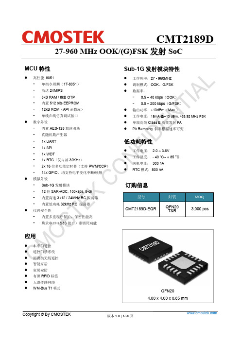
MCU特性CMT2189D 27-960 MHz OOK/(G)FSK发射SoCSub-1G发射模块特性QFN204.00 x 4.00 x 0.85 mm简介CMT2189D是内嵌增强型1T-8051内核的低功耗SoC RF发射器:1. 该系列芯片支持27~960 MHz,OOK调制或(G)FSK调制的无线发射功能;2. 高效单端PA,输出功率可调范围0~+13dBm,+13dBm发射时仅需18mA;3. 8 kB OTP程序存储体和12 kB ROM (用于存储API函数库);声明●无锡泽太微电子有限公司(以下简称泽太微或泽太)保有在不事先通知的情况下而修改这份文档的权利。
泽太微认为提供的信息是准确可信的。
本文档信息于2019年9月开始使用。
在实际进行生产设计时,请参阅各产品最新的数据手册等相关资料以获取本公司产品的最新规格。
●泽太微对本手册拥有包括版权等知识产权,受法律保护。
未经本公司事先书面许可,任何单位及个人不得以任何方式或理由对本手册进行复制、修改、抄录、传播等。
本文件所登载内容的错误,本公司概不负责。
●泽太微对于因使用本文件中列明的本公司产品而引起的,对第三方的专利,版权以及其它知识产权的侵权行为概不负责。
本文件登载的内容不应视为泽太微对其他公司或个人所拥有的专利,版权以及其它知识产权做出任何明示或默示的许可及授权。
●本文件中的电路、软件以及相关信息仅用以说明半导体产品的运作和应用示例。
用户如在设备设计中应用本文件中的电路、软件以及相关信息,应自行负责。
对于用户或其他人因使用了上述电路、软件以及相关信息而引起的任何损失,泽太微概不负责。
●另外,泽太微的产品不建议应用于生命相关的设备和系统。
在使用该器件中因为设备或系统运转失灵而导致的损失,泽太微不承担任何责任。
●虽然本公司致力于提高半导体产品的质量及可靠性,但用户应知晓并同意,我们仍然无法完全消除出现产品缺陷的可能。
为了最大限度地减少因本公司半导体产品故障而引起的对人身、财产造成损害(包括死亡)的危险,用户务必在其设计中采用必要的安全措施,如冗余度、防火和防故障等安全设计。
Nsiway NNSS44335588 超低EMI、无需滤波器、5W+3W×2的2.1声道 用户手
10.1
TQFN4×4-28 封装尺寸................................................................................................................... 18
10.2
SOP-28 封装尺寸............................................................................................................................ 19
7.3
NS4358 引脚功能描述 ..................................................................................................................... 9
7.4
芯片印章说明 ................................................................................................................................. 10
NS4358
超低EMI、无需滤波器、5W+3W×2的2.1声道+3D环绕立体声数字音频功放
NS4358 用户手册 V1.1
深圳市纳芯威科技有限公司 2011 年 10 月
Nsiway
1
日期
2011-3-11 2011-10-11
NS4358
超低EMI、无需滤波器、5W+3W×2的2.1声道+3D环绕立体声数字音频功放
接口器件

1、 RS-485概述
EIA RS-485标准
标准最初由电子工业协会EIA 于1983 年制订 多点双向通信能力即允许多个发送器连接到同一条总线上 增加了发送器的驱动能力和冲突保护特性 扩展了总线共模范围
一、RS232-TTL接口芯片
1、 RS-232-C介绍 2、 RS232-TTL接口芯片MAX232
一、RS232-TTL接口芯片-- RS-232-C介绍
一、RS232-TTL接口芯片-- RS-232-C介绍
RS-232-C接口串行通讯方式特点: 使用线路少、成本低,避免了多条线路特性的不一致而被 广泛采用。 接口的信号电平值较高,易损坏接口电路的芯片,又因为 与TTL 电平不兼容故需使用电平转换电路方能与TTL电路连 接。 接口使用一根信号线和一根信号返回线而构成共地的传输 形式, 这种共地传输容易产生共模干扰。 总线上只允许连接1个收发器。 单端驱动非差分接收电路,因而存在着传输距离不太远(最 大传输距离15m)和传送速率不太高(最大位速率为20Kb/s) 的问题。远距离串行通信必须使用Modem,增加了成本。
连接方式
总线匹配
是否对RS-485 总线进行终端匹配取决于数据传输速率、 电缆长度及信号转换速率 UART是在每个数据位的中点采样数据的只要反射信号在 开始采样时衰减到足够低就可以不考虑匹配
经验性的准则可以用来判断在什么样的数据速率和电缆 长度时需要进行匹配:当信号的转换时间上升或下降时 间超过电信号沿总线单向传输所需时间的3倍以上时就可 以不加匹配
2001年USB OTG补充规范使外部设备可以摆脱PC机,实现在任何两 台设备之间直接通信;
CKS32F103C8T6中科芯CKS32位单片机
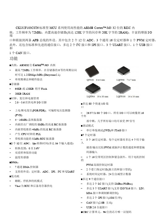
CKS32F103C8T6标准型 MCU 系列使用高性能的 ARM® Cortex™-M3 32 位的 RISC 内核,工作频率为 72MHz,内置高速存储器(高达 128K 字节的闪存和 20K 字节的 SRAM),丰富的增强 I/O端口和联接到两条 APB 总线的外设。
其中包含 2 个 12 位 ADC、3 个通用 16 位定时器和 1 个 PWM 定时器,此外,还包含标准和先进的通信接口:多达 2 个 I2C 接口和 SPI 接口、3 个 USART 接口、1 个 USB 接口和1 个 CAN 接口。
功能■内核:ARM32位Cortex™-M3 内核−最高72MHz工作频率,在存储器的0等待周期访问时可达1.25DMips/MHz (Dhrystone2.1)−单周期乘法和硬件除法■存储器−64KB 或 128KB 程序 Flash−20KB SRAM■时钟、复位和电源管理− 2.0~3.6伏供电和I/O引脚■多达80个快速I/O端口−上电/断电复位(POR/PDR)、可编程电压监测器(PVD)−4~16MHz晶体振荡器−内嵌经出厂调校的8MHz的高速RC振荡器−内嵌带校准的40kHz的低速RC振荡器−产生CPU时钟的PLL−带校准功能的32kHz RTC振荡器■2个12位ADC,1μs转换时间(多达16个输入通道) −转换范围:0至3.6V−双采样和保持功能−温度传感器■DMA:−7通道DMA控制器−支持的外设:定时器、ADC、SPI、I2C和USART ■低功耗−睡眠、停机和待机模式−V BAT为RTC和后备寄存器供电−26/37/51/80个I/O口,所有I/O口可以映像到16个外部中断;几乎所有端口均可承受5V信号■调试模式−串行单线调试(SWD)和JTAG接口■7个定时器−3个16位定时器,每个定时器有多达4个用于输入捕获/输出比较/PWM或脉冲计数的通道和增量编码器输入−1个16位带死区控制和紧急刹车,用于电机控制的PWM高级控制定时器−2个看门狗定时器(独立的和窗口型的)−系统时间定时器:24位自减型计数器■多达9个通信接口−多达2个I2C接口(支持SMBus/PMBus)−多达3个USART接口(支持ISO7816接口,LIN,IrDA接口和调制解调控制)−多达2个SPI接口(18M位/秒)器件对比CKS32F103x8(B)产品功能和外设配置产品型号外围接口CKS32F103C8/CB CKS32F103RB CKS32F103VB 闪存- K 字节64 128 128 128SRAM- K 字节20 20 20定时器通用目的 3 3 3 高级控制 1 1 1 SPI 2 2 2 I2C 2 2 2通信接口USART 3 3 3 USB 1 1 1CAN 1 1 1 GPIO 端口(通道数) 37 51 8012 位同步 ADC 2 2 2(通道数) 10 channels 16 channels 16 channels CPU 频率72 MHz工作电压 2.0V ~3.6V工作温度环境温度:-40℃~ +85℃/-40℃~+105℃结温度:-40℃~+125℃封装LQFP48 LQFP64 LQFP100订购信息托盘装产品型号封装形式盘装数盒装盘盒装数箱装盒箱装数CKS32F103C8T6 LQFP48 250PCS/盘10 盘/盒2500PCS/盒 6 盒/箱15000PCS/箱CKS32F103CBT6 LQFP48 250 PCS/盘10 盘/盒2500PCS/盒 6 盒/箱15000 PCS/箱CKS32F103RBT6 LQFP64 160 PCS/盘10 盘/盒1600 PCS/盒 6 盒/箱9600 PCS/箱CKS32F103VBT6 LQFP100 90 PCS/盘10 盘/盒900 PCS/盒 6 盒/箱5400 PCS/箱目录1.介绍 (1)2. 规格说明 (2)2.1 概述 (2)2.1.1 ARM®的Cortex™-M3 核心并内嵌闪存和 SRAM (2)2.1.2 内置闪存存储器 (2)2.1.3 CRC(循环冗余校验)计算单元 (3)2.1.4 内置 SRAM (3)2.1.5 嵌套的向量式中断控制器(NVIC) (3)2.1.6 外部中断/事件控制器(EXTI) (3)2.1.7 时钟和启动 (3)2.1.8 自举模式 (4)2.1.9 供电方案 (4)2.1.10 供电监控器 (4)2.1.11 调压器 (4)2.1.12 低功耗模式 (5)2.1.13 DMA (5)2.1.14 RTC(实时时钟)和后备寄存器 (5)2.1.15 定时器和看门狗 (6)2.1.16 I2C 总线 (7)2.1.17 通用同步/异步收发器(USART) (7)2.1.18 串行外设接口(SPI) (7)2.1.19 控制器区域网络(CAN) (8)2.1.20 通用串行总线(USB) (8)2.1.21 通用输入输出接口(GPIO) (8)2.1.22 ADC(模拟/数字转换器) (8)2.1.23 温度传感器 (9)2.1.24 串行单线 JTAG 调试口(SWJ-DP) (9)3. 引脚定义 (12)4. 存储器映像 (20)5. 电气特性 (21)5.1.1 最小和最大数值 (21)5.1.2 典型数值 (21)5.1.3 典型曲线 (21)5.1.4 负载电容 (21)5.1.5 引脚输入电压 (22)5.1.6 供电方案 (23)5.1.7 电流消耗测量 (23)5.2 绝对最大额定值 (24)5.3 工作条件 (25)5.3.1 通用工作条件 (25)5.3.2 上电和掉电时的工作条件 (25)5.3.3 内嵌复位和电源控制模块特性 (26)5.3.4 内置的参照电压 (27)5.3.5 供电电流特性 (27)5.3.6 外部时钟源特性 (31)5.3.7 内部时钟源特性 (35)5.3.8 PLL 特性 (36)5.3.9 储存器特性 (36)5.3.10 EMC 特性 (37)5.3.11 绝对最大值(电气敏感性) (38)5.3.12 I/O 端口特性 (39)5.3.13 NRST 引脚特性 (42)5.3.14 TIM 定时器特性 (43)5.3.15 通信接口 (43)5.3.16 CAN(控制器局域网络)接口 (48)5.3.17 12 位 ADC 特性 (48)5.3.18 温度传感器特性 (52)6. 封装特性 (53)6.1 封装机械数据 (53)6.2 热特性 (57)7. 型号命名 (58)8. 版本历史 (59)1.介绍本文给出了 CKS32F103x8 和 CKS32F103xB 标准型 MCU 产品的器件特性。
集成电路MM1538应用设计
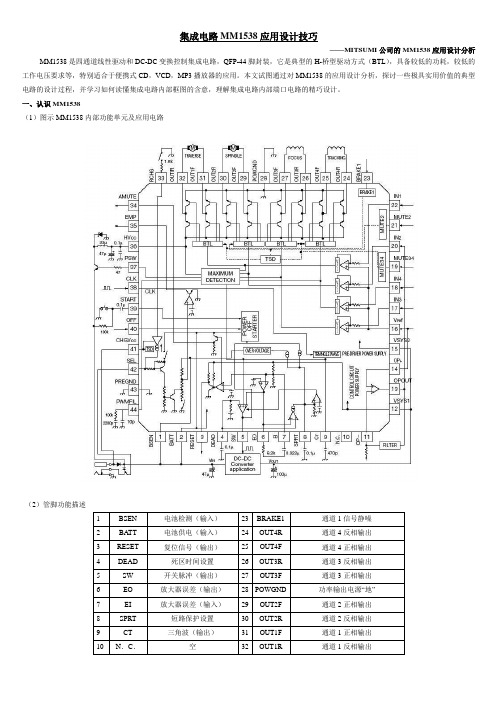
集成电路MM1538应用设计技巧——MITSUMI公司的MM1538应用设计分析MM1538是四通道线性驱动和DC-DC变换控制集成电路,QFP-44脚封装,它是典型的H-桥型驱动方式(BTL),具备较低的功耗,较低的工作电压要求等,特别适合于便携式CD,VCD,MP3播放器的应用。
本文试图通过对MM1538的应用设计分析,探讨一些极具实用价值的典型电路的设计过程,并学习如何读懂集成电路内部框图的含意,理解集成电路内部端口电路的精巧设计。
一、认识MM1538(1)图示MM1538内部功能单元及应用电路(2)管脚功能描述二、功能模块MM1538内部按功能可分为以几个模块:开关机模块、主电源管理模块、伺服驱动模块、电池检测及充电模块,还有部分杂项功能模块。
1、开、关机模块开、关机部分:所谓开机,就是在其第39(START)脚施加“低电平”时(参考应用电路,按开关键)MM1538内部振荡器工作,⑤、37端输出PWM脉冲信号控制DC-DC变换器工作(后面讲述)——系统上电;所谓关机就是在其第40(OFF)脚施加“低电平”时,MM1538内部振荡器停振,⑤、37端不再输出PWM脉冲信号——电路失电,系统恢复到待机状态。
下图分别是39、40的内部电路结构,其中开机电路三极管发射极连接电源BATT——电池电源,而关机电路三极管发射极连接电源是VSYS1,VSYS1是系统上电,DC-DC变换回送到MM1538内部的电源。
为什么这样设计呢?因为当整个系统都没有电源时,开机电路只能使用电池电源;当系统上电后DC-DC变换器工作,产生电源VSYS1,回送到IC内部,所以关机控制电路电源用VSYS1。
反之,若BATT 和VSYS1对调,从图(1)可以看出系统肯定不能开机;从图(2)可以看出电路在待机状态依然有控制作用——这显然不合适!另外,一般来说40脚总是连接MCU 的一个控制端口,待机状态下,控制端口没有电压,电路中有一条放电通路:BATT→IC內部三极管→27K电阻→40脚→MCU的一个控制端口→GND。
2SK2380资料

3
(0.44) 0.88+0.05 – 0.03
I Features
0.12+0.05 – 0.02
1 2
3°
Unit µA nA V V mS pF pF pF
Silicon Junction FETs (Small Signal)
PD Ta
150 240 Ta=25˚C 125 200 200 VGS=0.4V
unit: mm
M Di ain sc te on na tin nc ue e/ d
1.60±0.05 (0.80)
(0.44)
(0.51)
0.28±0.05 (0.51)
(0.80) (0.80) 1.60+0.05 – 0.03
0.60+0.05 – 0.03
I Absolute Maximum Ratings (Ta = 25°C)
Silicon Junction FETs (Small Signal)
2SK2380
Silicon N-Channel Junction FET
For impedance conversion in low frequency For infrared sensor
0.28±0.05
0.80±0.05
Parameter Symbol Gate to Drain voltage VGDO VGSO ID IG
3°
Ratings −40 −40 ±1 10
Unit V V
Gate to Source voltage Drain current Gate current
mA
Allowable power dissipation Channel temperature Storage temperature
RFID相关射频芯片基本介绍与应用

RFID相关射频芯片基本介绍与应用(一)RC530概述:RC530是NXP 公司出品的应用与13.56MHz非接触式通信中高集成读卡IC系列中的一员,该芯片完全集成了在13.56MHz下所有类型的被动非接触式通信方式和协议。
MFRC530支持ISO14443A所有的层。
RC530的外围电路入图所示。
该电路由接收电路和单片机接口电路两部分组成。
由于RC530内部接收部分使用一个受益于副载波双边带的概念装入卡响应的调整。
推荐使用内部产生的VMID电势作为RX脚的输入电势。
为了提供一个稳定的参考电压,必须在VIMD脚接一个对地的电容C9,RX和VMID必须连接一个分压IC卡将回复自己UID,如果没有碰撞阅读器将收到完整的电路由R9,R10构成,而且天线与分压器间还需要用一个电容C10串接。
由于IC卡工作在13.56Mhz下。
石英晶体在产生用于驱动RC530和天线的13.56Mhz时钟时,还会产生更高频率的谐波。
因此必须加上由L1,L2,C11,C13组成的低通滤波电路。
(二)MF RC531概述MF RC531 是应用于13.56MHz 非接触式通信中高集成读写卡芯片系列中的一员。
该读写卡芯片系列利用了先进的调制和解调概念,完全集成了在13.56MHz 下所有类型的被动非接触式通信方式和协议。
芯片管脚兼容MF RC500、MF RC530 和SL RC400。
MF RC531 支持ISO/IEC14443A/B 的所有层和MIFARE? 经典协议,以及与该标准兼容的标准。
支持高速MIFARE?非接触式通信波特率。
内部的发送器部分不需要增加有源电路就能够直接驱动近操作距离的天线(可达100mm)。
接收器部分提供一个坚固而有效的解调和解码电路,用于ISO14443A 兼容的应答器信号。
数字部分处理ISO14443A 帧和错误检测(奇偶&CRC)。
此外,它还支持快速CRYPTO1 加密算法,用于验证MIFARE 系列产品。
HS1528P无线遥控芯片电子钥匙芯片编码解码芯片
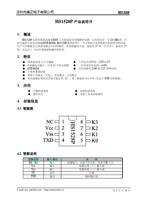
HS1528P产品说明书1.概述HS1528P是采用低耗高速CMOS工艺制造的专用编解码电路,它内部包含一个32×2Bit的一次性可编程只读电存储器(OTP-ROM)。
HS1528P提供给用户一个方便的开发和检验它们的程序的环境。
用户可以根据自己需要来确定不同的编码,有两种编码可选,最低有220种(百万次),最高有240种(万亿次),可以有效地降低编码重复率。
2.特征◆低静态电流,小于1.4µA◆工作电压范围宽:1.8V~5.5V◆4按键组合输入,可有15个组合按键◆一位码宽误差范围:±10%◆OTP-ROM◆可以选择发2240或1527两种码型◆小体积8脚封装◆两种工作模式(可选):省电模式、正常模式◆每次按键必须发送2帧才能完毕,第一、第二帧地址可以不同(决定于OTP内的数据)3.应用◆车辆防盗系统◆家庭防盗系统◆遥控玩具◆其他工业或家庭遥控4.封装信息4.1管脚图4.2管脚说明5.电路框图6.极限参数(Ta=25℃)范围电源电压-0.3~5.5输入电压-0.3~Vcc+0.3输出电压-0.3~Vcc+0.3Vcc=12V)工作温度储存温度7.电气参数(除非特殊说明:Tamb=25℃)符号8.功能说明8.1功能描述HS1528P通过烧写器来烧写地址位,通过按键(K0~K3)脚配对相应的数据位,编码成一个专用字码,当一个或几个按键脚(K0~K3)同时接到VCC(高电平)时由TXD脚输出此字码,再通过射频调制器发射。
该发射的字码通过射频解调接收器接收并还原该字码。
单片机解析该还原后的字码。
这样就构成了一个完整的编解码遥控控制系统。
HS1528P采用内置RC电路,省去一个外置振荡电阻。
8.2位码位码是编码波形的基本单元,可分为A/D (地址/数据)位和syn (同步)位。
8.2.1A/D (地址或数据)位8.2.1.1“0”码“0”码(35.2a )是一个高低电平宽度比为8.8a :26.4a 的脉冲(先高后低)。
2SC2383中文资料(toshiba)中文数据手册「EasyDatasheet - 矽搜」

(V)
0.1
Collector-emitter saturation voltage
CE (sat)
IC/IB = 10
V 0.05
5 0.03
0.01
5 10
30
100
300
1000
Collector current I C (mA)
VCE (sat) – IC
0.5
Common emitter 0.3 IC/IB = 10
• 产品适用于一般电子应用(如电脑,个人设备,办公设备,测量设备,工业机器人和家用电子电器)或特定的应用,明确本文中提到的使用.
产品既不打算,也没有必要使用设备或需要非常高水平的质量和/或可靠性和/或故障或失败的系统,其中可能造成的生命损失,人身伤害,重大财产损 失或严重的公众影响( “误用”).非预期使用包括,但不限于核设施使用的设备,在航空航天工业中使用的设备,医疗设备,用于汽车,火车,轮船 等运输,交通信号设备,用于控制发火或爆炸装置,安全装置的设备,电梯和自动扶梯,涉及到电力设备,以及设备在金融相关领域.不要使用产品的 误用,除非本文档中的特别许可.
0.005
3
10
30
100
300
Collector-emitter voltage V CE (V)
4
2009-12-21
芯片中文手册,看全文,戳
2SC2383
限制产品用途
• 东芝公司及其子公司和附属公司(统称为“TOSHIBA”),保留对本文档的更改信息的权利,以及相关的硬件,软件和系统(统称为“产品”),恕不另行通 知.
1 ms* 10 ms*
0.1 Collector current I
2.4G芯片
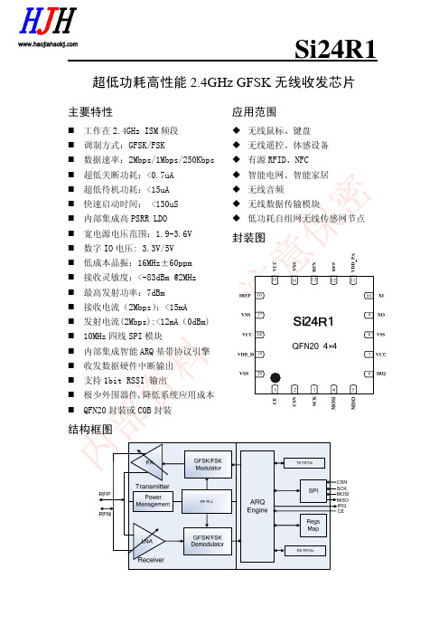
Si24R1超低功耗高性能 2.4GHz GFSK 无线收发芯片主要特性工作在 2.4GHz ISM 频段 调制方式:GFSK/FSK 数据速率:2Mbps/1Mbps/250Kbps 超低关断功耗:<0.7uA 超低待机功耗:<15uA 快速启动时间: <130uS 内部集成高 PSRR LDO 宽电源电压范围:1.9-3.6V 数字 IO 电压: 3.3V/5V 低成本晶振:16MHz±60ppm 接收灵敏度:<-83dBm @2MHz 最高发射功率:7dBm 接收电流(2Mbps) :<15mA 发射电流(2Mbps):<12mA(0dBm) 10MHz 四线 SPI 模块 内部集成智能 ARQ 基带协议引擎 收发数据硬件中断输出 支持 1bit RSSI 输出 极少外围器件,降低系统应用成本 QFN20 封装或 COB 封装应用范围无线鼠标、键盘 无线遥控、体感设备 有源 RFID、NFC 智能电网、智能家居 无线音频 无线数据传输模块 低功耗自组网无线传感网节点封装图结构框图Si24R1术语缩写术语 ARQ ART ARD BER CE CRC CSN DPL GFSK IRQ ISM LSB Mbps MCU MHz MISO MOSI MSB PA PID PLD RX TX PWR_DWN PWR_UP RF_CH RSSI RX RX_DR SCK SPI TX TX_DS XTAL 描述 Auto Repeat-reQuest Auto ReTransmission Auto Retransmission Delay Bit Error Rate Chip Enable Cyclic Redundancy Check Chip Select Dynamic Payload Length Gaussian Frequency Shift Keying Interrupt Request Industrial-Scientific-Medical Least Significant Bit Megabit per second Micro Controller Unit Mega Hertz Master In Slave Out Master Out Slave In Most Significant Bit Power Amplifier Packet Identity Payload RX TX Power Down Power UP Radio Frequency Channel Received Signal Strength Indicator Receiver Receive Data Ready SPI Clock Serial Peripheral Interface Transmitter Transmit Data Sent Crystal 中文描述 自动重传请求 自动重发 自动重传延迟 误码率 芯片使能 循环冗余校验 片选 动态载波长度 高斯频移键控 中断请求 工业-科学-医学 最低有效位 兆位每秒 微控制器 兆赫兹 主机输入从机输出 主机输出从机输入 最高有效位 功率放大器 数据包识别位 载波 接收端 发射端 掉电 上电 射频通道 信号强度指示器 接收机 接收数据准备就绪 SPI 时钟 串行外设接口 发射机 已发数据 晶体振荡器Si24R1目 录1、简介.................................................. 4 2、引脚信息 .............................................. 5 3、工作模式 .............................................. 6 4、寄存器映射表 .......................................... 9 5、主要参数指标 ......................................... 10 6、封装................................................. 12 7、典型应用原理图 ....................................... 14 8、订单信息 ............................................. 17 9、技术支持与联系方式 ................................... 18 附: 典型配置方案 ....................................... 19Si24R11、简介Si24R1 是一颗工作在 2.4GHz ISM 频段,专为低功耗无线场合设计,集成嵌 入式 ARQ 基带协议引擎的无线收发器芯片。
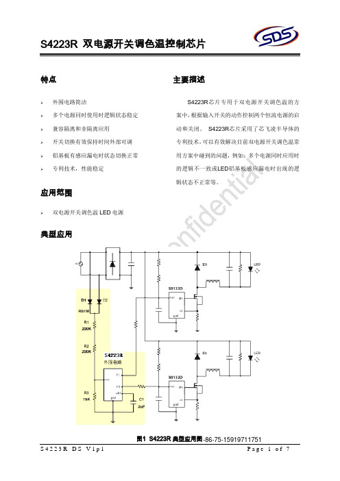
双电源开关调色温控制芯片 S4223R 说明书
Page 7 of 7 Page 7 of 7
S4223R-DS-V1p1
Page 6 of 7
S4223R 双电源开关调色温控制芯片
------------------------------------------------------------------------------------------
S4223R-DS-V1p1
2)声明:
. SDS保留说明书的更改权,恕不另行通知!
• 任何半导体产品特定条件下都有一定的失效或发生故障的可能,买方有责任在使用芯飞凌产品进行系统设计 和整机制造时遵守安全标准并采取安全措施,以避免潜在失败风险可能造成人身伤害或财产损失情况的发生!
• 产品提升永无止境,我公司将竭诚为客户提供更优秀的产品!
条件 Ivcc=2mA Ivcc=23V
P1(P2)=5V
典型值 24 15 5.6 5 1.5 1
单位 V uA V mA mA uA
功能说明
1. 供电
如图 1 所示:S4223R 的供电脚 VCC 通过电 阻 R1,R2 和 D1 连接到 AC 的输入端中一极, S4223R 的地线与恒流电源的地线相连。 由于考 虑到最高的交流电压和电阻的耐压,如果该供电电 阻使用的是贴片电阻建议两个串联。 电阻 R3 为 下拉电阻,它的作用为滤除由于 LED 铝基板的感 应漏电造成的虚拟电压。
S4223R-DS-V1p1
Page 2 of 7
S4223R 双电源开关调色温控制芯片
电气特性
( 除非特别说明,VCC=12V且Ta=25oC )
描述 供电脚 VCC 的限制电压 工作电流 内部供电电压 VCC 最大下拉电流 P1 和 P2 的下拉能力 状态保持时的内部工作电流
STR2A153 2A152 2A155 芯片

晶体管应用说明:推荐自动汽车AEC-Q200晶体管芯片用于Skyworks Si5118、Si533

AN1239: Recommended Automotive AEC-Q200 Crystals for Skyworks Si5118,Si5332, and Si5225x Clock GeneratorsThis application note lists several recommended AEC-Q200 crys-tals, which have undergone in-circuit testing and specification re-views. The list is meant as a starting point to help in the crystal selection process. Additional information on selecting appropriate crystal loading capacitance for the Si5118, Si5332, and Si52254/8 devices is also included.KEY POINTS•List of recommended AEC-Q200 crystals for use with Si5332, Si5118, and Si5225x Clock Generators•Useful information on CBPro’s Adjusted Capacitance setting for Si5332 designs •Useful information on calculating external crystal loading capacitance for Si5225x and Si5118 based designsTable of Contents1. Description (3)2. Recommended AEC-Q200 Crystals (4)3. “Adjusted Capacitance” Value for Si5332 Using ClockBuilder Pro (CBPro) (5)4. Calculating Crystal Loading Capacitance for Si52254/8 and Si5118 (6)5. Revision History (7)AN1239: Recommended Automotive AEC-Q200 Crystals for Skyworks Si5118, Si5332, and Si5225x Clock Generators • Description1. DescriptionThis document contains a recommended list of automotive AEC-Q200 crystals for use with Skyworks Si5118, Si5332-AM1/2/3, and Si52254/8 automotive grade clock generator devices, as well as additional crystal usage information specific to Si5118, Si5332, and Si52254/8.Crystals2. Recommended AEC-Q200 CrystalsThe following list contains select crystal devices reviewed and tested with the Si5118, Si5332, and Si52254/8. The crystal list below should not be interpreted as restricting crystal selection to only those crystals on this list. Instead, this list is a quick reference starting point when selecting an AEC-Q200 crystal for use with the Si5118, Si5332, or Si52254/8 automotive devices. Other AEC-Q200 crystals meeting Si5118, Si5332, and Si52254/8 data sheet specifications should be considered as potentially viable solutions as well.Table 2.1. List of Recommended Automotive AEC-Q200 Crystals for Use with Si5118, Si5332, and Si52254/8for Si5332 Using ClockBuilder Pro (CBPro)3. “Adjusted Capacitance” Value for Si5332 Using ClockBuilder Pro (CBPro)The Si5332 device has internal adjustable crystal loading capacitors that can, optionally, be used to provide the required crystal loading capacitance without the need for adding external capacitors. It is important to present the correct loading capacitance to the crystal for accurate frequency of operation. Most crystals require loading capacitance in the range of 8 to18 pF. These are small values, but accuracy in providing the correct total loading capacitance is required for accurate frequency of operation.The two main contributors to total crystal loading capacitance are:•Capacitors added to the PCB for crystal loading purposes•PCB stray capacitancePCB stray capacitance should not be ignored. For example, the Si5332 EVBs have a PCB stray capacitance of about 2.75 pF. If usinga crystal requiring 8 pF of loading, with 2.75 pF of stray capacitance, only an additional 5.25 pF of capacitance is needed, (8 pF –2.75 pF) = 5.25 pF. The 5.25 pF value is what we call “Adjusted Capacitance” since it has been adjusted to account for PCB stray capacitance.In the “Adjusted Capacitance” entry step in CBPro, the value to enter is the crystal’s required loading capacitance MINUS the PCB stray capacitance. If you instead enter the full required crystal loading capacitance, your clock generator will operate at a frequency lower than expected due to the unaccounted-for PCB stray capacitance. If you do not know your PCB’s stray capacitance, a good estimate would be ~ 2 pF for a 4+ layer FR4 PCB.Figure 3.1. CBPro Adjusted Capacitance Entry Screen4. Calculating Crystal Loading Capacitance for Si52254/8 and Si5118The Si52254/8 and Si5118 do not have internal adjustable crystal loading capacitors. This requires the addition of external crystal loading capacitors (External CL). In this case, not only should PCB stray capacitance be considered, but Si52254/8, or Si5118, device stray capacitance must also be considered. (Note: Device stray capacitance was not a concern for the Si5332 when using CBPro because CBPro automatically takes Si5332 Device stray capacitance into account .)Both the Si52254/8 and Si5118 devices have a device stray capacitance value of 2.5 pF .The equation for calculating the required added external loading capacitance for Si52254/8 and Si5118 is shown below:External added CL EXT = (Crystal CL – PCB Stray capacitance – Si52254/8 or Si5118 stray capacitance)Example :Assuming crystal CL = 12 pF, PCB stray = 2 pF, and Si52254/8 stray of 2.5 pF:Example External added CL EXT = (12 – 2 – 2.5) = 7.5 pF of required external loading capacitance.The external loading capacitance (CL EXT ) is added to the Si52254/8 (or Si5118) as two capacitors, one between XA and ground and one between XB and ground, as shown in the figure below marked C1 and C2. The capacitors should be the same value (C1 = C2)and are effectively connected in series. The values must be calculated such that the series combination of C1 and C2 are equal to therequired added external capacitance.Figure 4.1. External Added Crystal Loading Capacitors on Si52254/8Therefore, for the required external added capacitance of 7.5 pF, the values for C1 and C2 should be as follows:C1 = C2 = (2 * 7.5 pF) = 15 pF (Two 15 pF in series = 7.5 pF)Direct Calculation of C1 & C2:To directly calculate the value of C1 and C2 for the Si52254/8 or Si5118, use the following formula:C1 = C2 = 2 * (Crystal CL – PCB Stray capacitance – 2.5 pF)Capacitance for Si52254/8 and Si5118AN1239: Recommended Automotive AEC-Q200 Crystals for Skyworks Si5118, Si5332, and Si5225x Clock Generators • Revision History 5. Revision HistoryRevision 0.2September, 2021•Added 50 MHz crystals and Si5118.Revision 0.1June, 2020•Initial release.Copyright © 2021 Skyworks Solutions, Inc. All Rights Reserved.Information in this document is provided in connection with Skyworks Solutions, Inc. (“Skyworks”) products or services. These materials, including the information contained herein, are provided by Skyworks as a service to its customers and may be used for informational purposes only by the customer. Skyworks assumes no responsibility for errors or omissions in these materials or the information contained herein. Skyworks may change its documentation, products, services, specifications or product descriptions at any time, without notice. Skyworks makes no commitment to update the materials or information and shall have no responsibility whatsoever for conflicts, incompatibilities, or other difficulties arising from any future changes.No license, whether express, implied, by estoppel or otherwise, is granted to any intellectual property rights by this document. Skyworks assumes no liability for any materials, products or information provided hereunder, including the sale, distribution, reproduction or use of Skyworks products, information or materials, except as may be provided in Skyworks’ Terms and Conditions of Sale.THE MATERIALS, PRODUCTS AND INFORMATION ARE PROVIDED “AS IS” WITHOUT WARRANTY OF ANY KIND, WHETHER EXPRESS, IMPLIED, STATUTORY, OR OTHERWISE, INCLUDING FITNESS FOR A PARTICULAR PURPOSE OR USE, MERCHANTABILITY, PERFORMANCE, QUALITY OR NON-INFRINGEMENT OF ANY INTELLECTUAL PROPERTY RIGHT; ALL SUCH WARRANTIES ARE HEREBY EXPRESSLY DISCLAIMED. SKYWORKS DOES NOT WARRANT THE ACCURACY OR COMPLETENESS OF THE INFORMATION, TEXT, GRAPHICS OR OTHER ITEMS CONTAINED WITHIN THESE MATERIALS. SKYWORKS SHALL NOT BE LIABLE FOR ANY DAMAGES, INCLUDING BUT NOT LIMITED TO ANY SPECIAL, INDIRECT, INCIDENTAL, STATUTORY, OR CONSEQUENTIAL DAMAGES, INCLUDING WITHOUT LIMITATION, LOST REVENUES OR LOST PROFITS THAT MAY RESULT FROM THE USE OF THE MATERIALS OR INFORMATION, WHETHER OR NOT THE RECIPIENT OF MATERIALS HAS BEEN ADVISED OF THE POSSIBILITY OF SUCH DAMAGE.Skyworks products are not intended for use in medical, lifesaving or life-sustaining applications, or other equipment in which the failure of the Skyworks products could lead to personal injury, death, physical or environmental damage. Skyworks customers using or selling Skyworks products for use in such applications do so at their own risk and agree to fully indemnify Skyworks for any damages resulting from such improper use or sale.Customers are responsible for their products and applications using Skyworks products, which may deviate from published specifications as a result of design defects, errors, or operation of products outside of published parameters or design specifications. Customers should include design and operating safeguards to minimize these and other risks. Skyworks assumes no liability for applications assistance, customer product design, or damage to any equipment resulting from the use of Skyworks products outside of Skyworks’ published specifications or parameters.Skyworks, the Skyworks symbol, Sky5®, SkyOne ®, SkyBlue™, Skyworks Green™, Clockbuilder ®, DSPLL ®, ISOmodem ®, ProSLIC ®, and SiPHY ® are trademarks or registered trademarks of Skyworks Solutions, Inc. or its subsidiaries in the United States and other countries. Third-party brands and names are for identification purposes only and are the property of their respective owners. Additional information, including relevant terms and conditions, posted at , are incorporated by reference.Portfolio/ia/timingSW/HW/CBProQuality/qualitySupport & Resources/supportClockBuilder ProCustomize Skyworks clock generators, jitter attenuators and networksynchronizers with a single tool. With CBPro you can control evaluationboards, access documentation, request a custom part number, export for in-system programming and more!/CBPro。
