CX3_20(emc)配置管理手册【Word版】22p
EMC.CX300磁盘阵列配置手册
Procedure created on: 10/30/06 12:52SITE AND CONFIGURATION INFORMATION:Installation/Upgrade Information:Change Control Ref Number:Installing or Upgrading CE:Installation/Upgrade Date/Time: (EST)Customer and Site Information:Customer Name:Site ID/Region or Country: |Lab Contact:Contact Phone Number:Site Address:Clarify Case Number:Array Information:Serial Number of Array(s):Software in configuration RevisionFLARE/Access LogixNavisphere AgentNavisphere ManagerPowerPathATF/CDEVxVM DMPSnapViewMirrorView/AMirrorView/SSAN Copy/SAN Copy/ECLARalert/OnAlertAdmsnapAdmhostEMC Replication Manager (ERM)REPORTING PROBLEMS:If you find any errors in this procedure or have comments regarding this application, please send email to CLARiiONProcedureGenerator@. Be sure to reference any modules by the correct filename (located to the right of the module title).CONFIGURATION DESCRIPTION:∙Product: CX-Series (CX200-CX700) *∙Activity: Install New Array and New Host∙Model: CX300∙Installation Type: Field Installed in EMC Cabinet∙Power Source Type: Standard AC Installation∙Software Release: Release 19 (02.19.xxx)∙Management Software: Navisphere GUI∙Manage a Legacy Array with Navisphere 6.x on the Same LAN: No∙Environment: Access Logix∙Connection Type: Switch (SAN)∙Hot Spare(s): No∙CLARalert: already installed∙Host 1: Solaris PCI∙ Boot Device: Server is Boot Device∙ Number of HBAs/NICs: Single HBA/NIC∙ Type of HBA/NIC: Emulex∙ Cluster Environment: Clustered host∙ Failover Type: PowerPath SE∙EIP/EIP-2 instructions: No∙Employee of: EMC Authorized Service Provider (ASP)∙∙* Unless otherwise noted, this procedure uses the term "CX-Series" to refer to CX3-80, CX3-40, CX3-40c, CX3-20, CX3-20c, CX700, CX600, CX500-Series, CX400, CX300-Series, and CX200-Series.WARNINGS:If this is a procedure for a cloned host, delete the HostIDFile.txt file before installing any CLARiiON software. Refer to EMC Knowledgebase article emc66921 for moreinformation.TABLE OF CONTENTS:To link immediately to a specific page within this procedure, position the cursor over the pagenumber on the right and click.Denotes a checkpointVerify you have reviewed the latest CLARiiON CCA rules cncca010_R002 (3)Review E-Lab Interoperability Navigator for additional config steps plstr020_R002 (3)Verify the customer has completed the following for PowerPath inpwp010_R003 (3)Verify the host is connected to the LAN cnlan010 _R001 (4)Install PowerPath SE on a Solaris host inpwp100_R007 (4)Install Navisphere Agent and CLI software on a Solaris server incli030_R001 (7)Service providers begin here to continue the installation procedure inpwp110_R001 (9)Install the SPS tray and unit(s) in the CX300/CX300i/CX200 cabinet incx3090_R003 (9)Install the mounting rails and enclosure(s) in the cabinet indae040_R003 (12)Set up a CX300/CX300i DAE2 disk enclosure (if applicable) incx3100_R001 (19)Set up a CX-Series DAE2P disk enclosure (if applicable) incx7070_R002 (21)Cable and power-up a CX300/CX300i storage system incx3120_R001 (25)Install the switch cnswt090 _R003 (29)Cable HBAs to switch ports and check connections inhba330_R003 (30)Cable CX300 SPs to switch ports and check connections cnspr090 _R001 (31)Configure the switch cnswt110 _R003 (31)Cable the CX300 to the LAN cnlan110_R001 (33)Install array software cnman810_R007 (34)Create switch zones and add them to the switch configuration cnswt100_R003 (36)Add persistent bindings to the Solaris Emulex kernel files cnsol020 _R001 (36)Add LUNs to the Solaris sd.conf configuration file (Emulex) cnlun080_R003 (37)Verify connection between SP Agent and host system cncli010_R001 (38)Verify each HBA sees its targets on a Solaris server cnhba090 _R001 (39)Set array properties in Navisphere Manager cnnav140_R004 (39)Create RAID groups in Navisphere Manager cnlun550_R007 (40)Create LUNs on RAID groups with Navisphere Manager cnlun560_R008 (41)Create storage groups and connect hosts cnlun570_R003 (42)Set failover settings for PowerPath (Solaris) cnfsw110_R003 (43)Allow Solaris server to see target LUNs cnlan030 _R001 (45)Make LUNs available to Solaris cnlun320_R002 (46)Configure PowerPath for missing devices (Solaris) inpwp060_R001 (47)Install the Navisphere Service Taskbar / Disk Replacement Utility innst020_R003 (47)For your own records: Collect environment configuration information instr090_R002 (50)Verify the presence of the Power Down Sequence Label cnpwr020_R004 (51)CLARalert Proactive Remote Support cnalr030_R001 (52)Enter the CX300 TLA part and serial numbers into Clarify database instr210_R006 (54)Verify you have reviewed the latest CLARiiON CCA rules cncca010_R0021. Verify you have reviewed the latest version of the CLARiiON CCA Rules document. Thedocument can be obtained by clicking the link provided below or by navigating to the CLARiiON Procedure Generator default installation folder (C:\Program Files\CLARiiON ProcedureGenerator\CCA_Rules.pdf).Open CLARiiON CCA Rules Document DoneTable of ContentsReview E-Lab Interoperability Navigator for additional config steps plstr020_R0022. Verify that you have read all footnotes that are associated with the tables displayed in the E-LabInteroperability Navigator Host Connectivity report. In some cases (e.g., when running aparticular revision of an operating system or operating system patch), the footnotes include additional steps that may need to be performed and are not included in this procedure. DoneTable of ContentsVerify the customer has completed the following for PowerPath inpwp010_R0033. IMPORTANT: Prior to the arrival of the service provider, the customer should complete thefollowing tasks (in the given order) as applicable to the configuration. However, theseinstructions are provided in the following modules in case the customer has not successfully completed the tasks. If these tasks are c omplete, then skip to the module titled ―Service providers begin here to continue the installation procedure‖.1. Connect the server to the LAN2. Install the correct HBAs/NICs and driver as stated in the E-Lab InteroperabilityNavigator (ESM)3. Set parameters to optimize the driver in a CLARiiON environment4. If applicable, remove ATF or CDE if migrating to PowerPath5. Install PowerPath6. Install the Host Agent DoneTable of ContentsVerify the host is connected to the LAN cnlan010_R0014. Verify that the host is connected to the LAN.If it is not connected, then attach the LAN cable to the Ethernet port on the back of the server. DoneTable of Contents∙Install PowerPath SE on a Solaris host inpwp100_R007 5. CAUTION: This procedure is specific to the installation of PowerPath version 5.0, which is thecurrent shipping version for Solaris hosts. For instructions on installing older versions ofPowerPath, refer to the applicable PowerPath installation manual available on PowerLink.PowerPath SE is the default policy on CLARiiON systems without a valid PowerPath license.Load balancing is not in effect and I/O routing on failure is limited to one host bus and one port on each storage processor. This policy is required for non-disruptive upgrades. It protectsagainst storage processor (SP) and backend failures, but not against HBA or host loop failures.PowerPath SE does not ship with a license key, because one is not required for installation.Verify the following prior to the installation of PowerPath SE:∙Verify that ATF or CDE is not installed on the Solaris host. If any versions of ATF or CDE are installed on the host, uninstall them and reconfigure applications andsystem services that use ATF pseudo device names to use standard Solaris nativenamed devices (cXtXdXsX) instead before continuing.∙Review the patch ReadMe files to determine which patches (if any) you want to install after PowerPath, and whether those patches have any added prerequisitesthat must be met before you install PowerPath.∙Determine if the PowerPath software you are installing requires the removal or presence of a previous version of PowerPath. Some full versions require theprevious version to be removed while others do not. Also, some patches requirethe full version to be present while others require it to be removed. Refer to thePowerPath Release Notes and/or PowerPath patch readme files for your specificversion to determine what needs to be present/removed and if and when a rebootis necessary in order to install your specific PowerPath software version and/orpatch. These documents are available on . Done6. Mount the PowerPath CD-ROM:a. Verify that you are logged in as root.b.Insert the CD-ROM in the CD-ROM drive.The CD should mount automatically. If it does not, then you must mount itmanually. For example, to mount the CD on /cdrom/cdrom0, enter:mount -F hsfs -r /dev/dsk/c x t y d z s0 /cdrom/cdrom0where x, y, and z are values specific to the host’s CD-ROM drive.For example: mount -F hsfs -r /dev/dsk/c0t2d0s0 /cdrom/cdrom07. Install PowerPath software:a. If you do not have a graphics terminal, run the script filename command to recordpkgadd output in the specified file. (After pkgadd completes, use CTRL-D to stoprecording the output.)b. Change to the /mount_point/UNIX/SOLARIS directory.∙On SPARC hosts, enter:cd /cdrom/cdrom0/UNIX/SOLARIS∙On Opteron hosts, enter:cd /cdrom/cdrom0/UNIX/SOLARIS_i386c. Start the installation by entering:/usr/sbin/pkgadd -d .NOTE: Note the required space and period after the -d parameter.d. At the packages available prompt, enter 1and press Enter.e. At the prompt for an installation directory for the program files, press Enter to acceptthe default base directory (/opt) or type the path to an alternate base directory andpress Enter.NOTE: PowerPath installs its files in /basedir/EMCPower; the installation processcreates the EMCPower subdirectory. Make a note of the name and location of thePowerPath base directory for future reference.f. At the prompt to continue the installation, enter y and press Enter.g. The screen will display information about the installation. At the prompt, enter q andpress Enter.h. If VERITAS VxVM is installed or will be installed, perform the applicable substepdepending on the version. Otherwise, skip this step.∙VERITAS VxVM version 4.1:If DGC devices were previously set as jbod, unset them as follows:vxddladm rmjbod vid=DGC∙VERITAS VxVM version 4.0 and earlier:Run the following command after PowerPath has been installed:vxddladm addjbod vid=DGC pagecode=0x83 offset=8 length=16This command needs to be run only once and will take effect on the nextreboot.8. After PowerPath is installed on the host, perform the following:a. Remove the CD-ROM as follows:∙If the CD-ROM volume management daemon vold is running, unmount andeject the CD-ROM. Enter the following command and remove the CD-ROM:eject∙If vold is not running, unmount the CD-ROM by entering the followingcommand and then ejecting the CD-ROM:unmount /cdrom/cdrom0b. If required by your specific PowerPath version or patch, reboot the host by entering:reboot -- -rNOTE: If the sd or ssd driver does not exist on the host, you will see a forceloadfailed warning during boot. You can safely ignore this warning.9. If necessary, install any PowerPath patches from the following URL:NOTE: A readme file that explains how to install the patch accompanies every patch release.This file will also state whether you need to reboot the host after the installation of the patch.Install the patch package by entering the following command:patchadd .10. Verify that PowerPath is installed properly on the host:a. Enter the command:pkginfo -1 EMCpowerYou should see output similar to the following:NOTE: When you install PowerPath on an AMD Opteron host, i386 appears inthe ARCH row.PKGINST: EMCpowerNAME: EMC PowerPathCATEGORY: systemARCH: sparcVERSION: 5.0.0_bxxxBASEDIR: /optVENDOR: EMC CorporationPSTAMP: cambridge951018123443INSTDATE: Feb 15 2006 08:24STATUS: completely installedFILES: 286 installed pathnames5 shared pathnames38 directories121 executables107843 blocks used (approx)b. Verify that the PowerPath and PowerPath Volume Manager kernel extensions areloaded on the host by entering:modinfo | grep emcYou should see output similar to the following:31 7bbfa000 2c28 163 1 emcp (PP Driver 5.0.0)32 7bb3a000 30ce8 154 1 emcpmpx (PP MPX Ext 5.0.0)33 1336620 21e60 - 1 emcpsf (PP SF 5.0.0)34 7ae00000 dada8 - 1 emcpsapi (PP SAPI Ext 5.0.0)35 12be610 12440 - 1 emcpcg (PP CG Ext 5.0.0)36 7bb7e6d0 3180 - 1 emcpgpx (PP GPX Ext 5.0.0)37 7b68fe88 78e8 - 1 emcpdm (PP DM Manager 5.0.0)38 7b7a7e10 2c8 - 1 emcpioc (PP PIOC 5.0.0)NOTE: The emcpmp , emcpmpc , emcpmpap , and emcpmpaa extensions present inprevious releases have been replaced by the emcpmpx extension in PowerPath 5.0for Solaris. Furthermore, the HighRoad (emcphr ) extension has been removedfrom PowerPath 5.0.Table of Contents∙ Install Navisphere Agent and CLI software on a Solaris server incli030_R00111. Verify the following requirements have been met before continuing:∙ The Solaris host is running a supported distribution of Solaris.∙ The supported HBA hardware and driver are installed.∙ Agent and/or CLI are not already installed. If either is installed, then remove eachone before continuing with the next step.∙ There is a configured TCP/IP network connection to allow the server to send LUNmapping information to the storage system and allow Manager or CLI tocommunicate with the storage system over the network.Done 12. Install the Host Agent and CLI software:a. If you are installing the Host Agent, ensure that each storage system is connectedto the Solaris server where you are installing the Host Agent.b. Verify that you are logged in as superuser (root) at the Solaris server.c. If any previous revision of Navisphere Agent or CLI is installed on the server,remove it before continuing.d. Insert the CD-ROM into the host’s CD -ROM drive.e. In a shell, enter the following commands:cd /cdrom/cdrom0pkgadd –d /solaris/naviagnt.pkgf. Select the packages to install by performing one of the following:∙Enter 1 (to install the Host Agent)∙Enter 2 (to install Navisphere CLI)∙Enter All (to install both Host Agent and CLI)g. Enter y at the next two prompts.The installation program looks for any Agent configuration files you may alreadyhave on your system. If the program does not find any agent configuration files,then you have finished installing the Agent; skip to step k below.If the program does find any existing configuration files, it displays a message likethe following:At Least 1 saved config file exists for Navisphere Agent.Please select 1 of the following:[1] Restore/etc/Navisphere/.Naviagent-config.000120:1059[2] Restore/etc/Navisphere/.Naviagent-config.000121:1408[3] QuitSelect number 1 -3.h. Select the existing file you want to serve as the Agent configuration file. Thesoftware will retain that file and rename it with the required Agent filename,agent.config.Generally, you will want to use the most recent file, as shown by the numeric datesuffix. To use the default configuration file, specify the number for the Quit option.i. When the installation of the Host Agent is complete, the following messageappears:Installation of <NAVIGENT> was successful.If you are also installing the CLI, the program prompts::Processing package instance <NAVICLI> from.....j. Answer y to the CLI installation prompts as you did for the Agent.k. When installation is complete, exit the /cdrom directory (for example, execute cd/).Run the eject command and then remove the CD from the host’s CD-ROM drive.IMPORTANT: Any user who can access the management station can change ordelete the Navisphere files you just installed. You may want to change permissionson these files to restrict access to them.13. Modify the user login scripts:Use a text editor (for example, vi) to modify login scripts as described below:∙ If you are running Common Desktop Environment, remove the comment from thelast line in $HOME/.dtprofile. The line should read: DTSOURCEPROFILE=true∙ Make the following additions to the specified paths in $HOME/.profile or $HOME/.cshrc, and export each path:Add the text /opt/Navisphere/bin to PATHAdd the text /opt/Navisphere/man to MANPATHAdd the text /opt/Navisphere/lib to LD_LIBRARY_PATHIMPORTANT: You must export each path after you have modified it.14. Enter the following command to start the Host Agent:/etc/init.d/agent startTable of Contents Service providers begin here to continue the installation procedure inpwp110_R00115. If the customer has completed all of the customer tasks stated earlier, then begin at this point to continue the installation procedure.DoneTable of Contents∙ Install the SPS tray and unit(s) in the CX300/CX300i/CX200 cabinet incx3090_R00316. Install the rails in the cabinet:a. After you decide where in the cabinet you want to install the SPS tray, find theunoccupied 1U section on the rear channels. It is suggested that you install theSPS tray immediately beneath the DPE or SPE, if possible. For more informationon EMC recommended device placement configurations, refer to the EMC Railsand Enclosures Field Installation Guide (P/N 300-001-799).NOTE: On the EMC 40U and 40U-C cabinets, the 1U increments are marked by ahorizontal line or small hole in the channel.b. From the front of the cabinet, insert the alignment pin on one mounting railassembly into the middle hole of the selected 1U space on a rear channel. Thefollowing figure shows the correct channel holes for the alignment pins.Donec. Extend the rail to the front cabinet channel. Align the holes of the front rail flange tothe inside of the channel, ensure that the rail is level, and then install two M5 x 16-mm Phillips securing screws in the top and bottom holes, as shown in the figurebelow.NOTE: Leave the screws slightly loose to allow for adjustment after you install thetray. Do not insert a screw in the middle hole yet.d. At the back of the cabinet, insert and tighten two M5 x16-mm securing screws inthe holes above and below the alignment pin, as shown above.e. Repeat steps b through d for the other rail assembly.17. Install a filler panel for SPS B (if applicable):If you are installing a single SPS unit, install the SPS filler unit over the SPS B space in the trayas shown in the figure below. If you are installing a typical configuration with two SPS units,skip this step.a. Align the filler unit to the inside left rear of the tray.b. Use 4 M4 x 8-mm panhead screws to secure the unit to the tray.18. Install the SPS tray in the cabinet:a. From the front of the cabinet, align the SPS tray with the channels on the mountingrails. Position the tray as shown in the figure below.b. Slide the tray onto the mounting rails in the cabinet, until the flanges of the tray areflush with the cabinet channels.c. Do not insert any new screws, but tighten the four securing screws (two on eachside) that hold the mounting rails to the channels.19. Install the SPS units in an SPS tray:a. Remove the SPS units from their packaging.b. Working from the front of the cabinet, slide the SPS units onto the tray as shown inthe figure below.NOTE: To eliminate potential bow caused by the weight of the SPS(s), press upon the middle of the tray with one hand while you secure the units to the tray. (Thetray will not bow if placed on the bottom of the cabinet.)c. Attach the front fastening bracket, and insert and tighten the 6 M4 x 10-mmflathead securing screws as shown in the figure above.d. Insert and tighten the 8 M4 x 8-mm panhead securing screws that secure the SPSunits to the back of the tray, as shown in the figure above.20. Install latch brackets and bezel:a. Use one Phillips M5 x 16-mm screw to secure a latch bracket to each frontchannel. (The brackets include small alignment bumps to correctly orient them to the channel).b. Press the bezel onto the latch brackets until it snaps into place.Table of ContentsInstall the mounting rails and enclosure(s) in the cabinet indae040_R00321. NOTE: Since EMC uses easily adjustable universal rails to mount these items in a NEMA-standard cabinet, these instructions apply to non-EMC cabinets as well.NOTE: It is recommended to locate a storage processor enclosure directly above the SPS tray. In configurations where a 3U disk enclosure shares an SPS with a processor enclosure, locate the disk enclosure directly above the processor enclosure. The 3U disk enclosures are typically stacked above their respective storage processor enclosure to facilitate the routing of Fibre Channel cables. If necessary, refer to the EMC Rails and Enclosures Field Installation Guide (P/N 300-001-799) for more information on specific device placement requirements within your cabinet.Done22. Install the adjustable rails:Physical placement of DAE and DAE2P chassis within a cabinetGoal: When installing chassis into a cabinet in the field, it is important that the physical placement of the DAE chassis types within the cabinet allows for standard cabling practices and allows DAE2P (Stiletto) chassis to be segregated on their own back-end loop whenever possible.Background: With the introduction of the DAE2P chassis, it now matters where a DAE2P is mounted within a cabinet in relation to other DAE2 chassis (FC or ATA).Mixing DAE types: The new design of the DAE2P chassis takes advantage of the point-to-point technology within the chassis. Because of this technology, it offers better backend fault isolation if a problem arises. This benefit can only be realized if the DAE2P chassis on a given backend bus are not mixed with the original DAE2. Since ATA-DAE chassis are also point to point within the enclosure, mixing them with DAE2P enclosures on the same backend loop will not compromise new backend isolation capabilities. For planned future cable tests however, loop segregation is suggested if possible.Because of the way we cable chassis together (Enclosure ID 0 of each bus, ascending up a cabinet with enclosure 1 of each bus etc), it is important that the physical position within the cabinet allows for the standard cabling we have been using in the field, while attempting to make back-end busses homogeneous.Guidelines in order of priority∙Balance back-end busses (qty of chassis/bus)∙Segregate chassis types by bus∙Maintain current cabling strategyNOTE: It is better to have a FC DAE on the same back-end bus as a Klondike ATA chassis rather than have it on the same bus as a DAE2PExamples:Example CX5001 DPE, 1 ATA and 3 DAE2P chassisSince the DPE is a Katana chassis, keep the ATA chassis on Loop 0 and cablethe 3 DAE2P chassis to bus 1.1_2 DAE2P1_1 DAE2P0_1 ATA1_0 DAE2P0_0 DPE/KatanaExample CX5001 DPE,2 ATA and 2 DAE2P chassisSince Bus 0 has the Katana Boot chassis, the 2 DAE2P chassis are placed onBUS 10_2 ATA1_1 DAE2P0_2 ATA1_0 DAE2P0_0 DPE/KatanaExample CX7002 DAE2P and 4 ATA chassis. The boot Chassis is a DAE2P.Install Both DAE2P chassis on BUS 01_1 ATA0_1 DAE2P3_0 ATA2_0 ATA1_0 ATABoot chassis0_0 DAE2PCX700 SPEchassisCX300 ExampleWith only 1 BUS available there is no option to segregate the DAE2P chassis. 0_3 DAE2P0_2 ATA0_1 ATA0_0 DPE Katanaa. Locate and unpack the rail kit that accompanied your enclosure. Verify that the kitincludes the following:∙ 2 adjustable rails – Note that the front edge of each rail is stamped L or R for left and right sides, when they face the cabinet front.∙12 Phillips M5 12.7mm screws∙ 2 clip nuts for M5 screws∙3U or 4U (front rack panels) with keysb. In most cases, the space into which you will install your enclosure is covered by a fillerpanel, which is attached to latch brackets.Remove any filler panel and use a flat-blade screwdriver or similar tool to pry off thelatch brackets as shown below.NOTE: The pre-drilled holes in the cabinet channels are based on the NEMA-standard U measurement. The holes are pre-drilled at distances of 1/2 inch, 5/8 inch, 5/8 inch (totaling one U), then 1/2 inch, 5/8 inch, 5/8 inch (another U), and so on. On EMC 40U and 40U-C cabinets, horizontal lines or small holes in the channel mark the 1Uincrements.c. From the front of the cabinet, insert the right rail alignment pins above and below thebottom U mark on the rear NEMA channel.d. Pull the adjustable rail forward to the inner side of the front channel (the surface facingthe rear of the cabinet), and align the four holes on the rail with those in the channel.e. Secure the rail to the front channel using two of the provided screws at the middle twoholes of the rail. Tighten the screws.f. Repeat steps c through e on the left side, with the left rail.g. If you are installing a 4U enclosure, secure a clip nut over the center hole in the top(fourth) U of the enclosure space on each front channel.h. From the rear of the cabinet, use two of the provided screws to secure each rail to therear channel. Leave the screws slightly loose to allow for adjustment after you installthe enclosure.23. Install the enclosure(s) (SPE, DPE2, DAE2, or DAE2P) in the cabinet:Physical placement of DAE and DAE2P chassis within a cabinetGoal: When installing chassis into a cabinet in the field, it is important that the physicalplacement of the DAE chassis types within the cabinet allows for standard cabling practices andallows DAE2P (Stiletto) chassis to be segregated on their own back-end loop wheneverpossible.Background: With the introduction of the DAE2P chassis, it now matters where a DAE2P ismounted within a cabinet in relation to other DAE2 chassis (FC or ATA).The new design of the DAE2P chassis takes advantage of the point-to-point technology withinthe chassis. Because of this technology, it offers better back-end fault isolation if a problemarises. This benefit can only be realized if all the chassis on a given back-end bus are DAE2Pchassis.Because of the way we cable chassis together (Enclosure ID 0 of each bus, ascending up a cabinet with enclosure 1 of each bus etc), it is important that the physical position within the cabinet allows for the standard cabling we have been using in the field, while attempting to make back-end busses homogeneous.Guidelines:∙Segregate chassis types by bus∙Maintain current cabling strategy∙Balance back-end busses (qty of chassis/bus)NOTE: It is better to have a FC DAE on the same back-end bus as a Klondike ATA chassis rather than have it on the same bus as a DAE2PExamples:Example CX5001 DPE, 1 ATA and 3 DAE2P chassisSince the DPE is a Katana chassis, keep the ATA chassis on Loop 0 and cablethe 3 DAE2P chassis to bus 1.1_2 DAE2P1_1 DAE2P0_1 ATA1_0 DAE2P0_0 DPE/KatanaExample CX5001 DPE,2 ATA and 2 DAE2P chassisSince Bus 0 has the Katana Boot chassis, the 2 DAE2P chassis are placed onBUS 10_2 ATA1_1 DAE2P0_2 ATA1_0 DAE2P0_0 DPE/KatanaExample CX7002 DAE2P and 4 ATA chassis. The boot Chassis is a DAE2P.Install Both DAE2P chassis on BUS 01_1 ATA0_1 DAE2P3_0 ATA2_0 ATA1_0 ATABoot chassis0_0 DAE2PCX700 SPEchassis。
EMC CX扩容(加硬盘)操作配置步骤
本例是在 CX 上面新加硬盘,创建 RAID,分配 LUN 提供空间到主机的整个过程
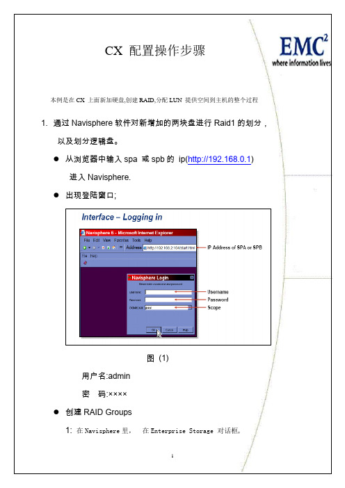
1. 通过 Navisphere 软件对新增加的两块盘进行 Raid1 的划分, 以及划分逻辑盘。 从浏览器中输入 spa 或 spb 的 ip(http://192.168.0.1) 进入 Navisphere. 出现登陆窗口;
这里的设备被分成了两组,实际上就是通过两个控制器看到的设备,其 中一组的状态为[active],表示这是当前的活动控制器。 修改文件/etc/lvm/lvm.conf 将 types = { “fd”,16} 改成 types = {“device-mapper”, 1} 保存后退出。 2) 在 EMC CX 存储上创建 FIMS 需要的分区 #pvcreate /dev/dm-0 ( 创建物理卷)
8
3. 上面的操作也可以通过 IE 管理界面来操作: 在 IE 中输入 switch ip 出现如下界面:
输入登录用户名和密码
在 zone--->create-->ports &Devices 迭中 1.1;1.3;1.6; 增加到 xone members 中
9
在 config--->create swB_FMSzone1 再增加到 config members 中
6
DS_16B3_A:admin> switchshow switchName: DS_16B3_A switchType: 26.2 switchState: Online switchMode: Native switchRole: Principal switchDomain: 1 switchId: fffc01 switchWwn: 10:00:00:05:1e:34:40:8e zoning: ON (spa0spb1hba1) switchBeacon: OFF Port Media Speed State ……………………………………………………………………………………………………… 0 id N2 Online F-Port 10:00:00:00:c9:45:5c:b0 1 id N2 Online F-Port 50:06:01:60:30:21:06:6f 2 id N2 Online F-Port 10:00:00:00:c9:42:81:5a 3 id N2 Online F-Port 50:06:01:69:30:21:06:6f 4 id N2 Online F-Port 21:00:00:e0:8b:1b:eb:c1 5 id N2 Online L-Port 1 public 6 id N2 Online F-Port 10:00:00:00:c9:51:00:69 7 id N2 Online F-Port 10:00:00:00:c9:51:8e:42 8 id N2 No_Light 9 id N2 No_Light
CX3-20产品介绍
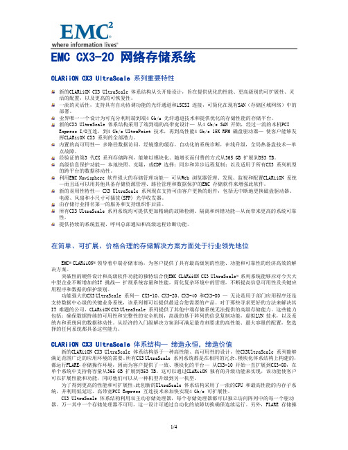
EMC CX3-20 网络存储系统CLARiiON CX3 UltraScale 系列重要特性新的CLARiiON CX3 UltraScale 体系结构从头开始设计,旨在提供优化的性能、更高级别的可扩展性、灵活的配置,以及更高的可恢复性。
一流的灵活性,支持具有自动协调功能的光纤通道和iSCSI 连接,可简化在现有SAN(存储区域网络)中的部署。
业界唯一一个设计为可充分利用端到端4 Gb/s 光纤通道技术和提供优化的存储性能的存储平台。
新的CX3 UltraScale 体系结构采用了端到端的高带宽设计—从4 Gb/s SAN 开始,经过一流的本机PCIExpress I/O互连,到4 Gb/s UltraPoint 技术,再到高性能4 Gb/s 15K RPM 磁盘驱动器—使客户能够发挥CLARiiON CX3 系列的全部潜力。
内置的高可用性—多路径数据访问,经镜像的缓存,自动化的系统诊断,在线升级,全局热备盘技术—单点故障。
经验证的第3 代CX 系列存储阵列,能够以模块化、随增长而付费的方式从365 GB 扩展到353 TB。
高级信息保护功能—本地快照、克隆,或CDP 选择;同步和异步远程复制;以及适用于所有CX3 系列机型的跨平台的数据移动性。
利用EMC Navisphere 软件强大的存储管理功能—可从Web 浏览器管理、发现、监视和配置CLARiiON 系统—而且还可以用其他具备存储资源管理、路径管理和数据保护的EMC 存储软件来增强此软件。
新的易用性特性— CX3 UltraScale 系列现在支持可由客户更换的组件,包括无中断地更换磁盘驱动器、电源、风扇和小尺寸可插拔(SFP) 光学收发器。
由存储行业排名第一的服务和支持组织作后盾。
所有CX3 UltraScale 系列系统均可提供更加精确的故障检测、隔离和纠错功能—从而带来更高的系统可靠性。
提供持续的系统监视、呼叫总部通知和高级远程诊断功能。
EMC CX系列存储日常管理维护和故障排除手册
一、ClariionCX系列产品硬件介绍1.ClariionCX系列产品的基本构成构成:由SPS,DPE/SPE和DAE三部分组成示例:CX4-960(图1-0)名词解释:SPS:StandbyPowerSupply,接DPE或者SPE+DAEOS,对WriteCache提供后备电源保护SPE:StorageProcessorEnclosure,包含两个全冗余的存储控制器DPE:DiskProcessorEnclosure,SPE和DAEOS在同一个EnclosureDAE:DiskArrayEnclosure,磁盘柜,包含15个硬盘槽位,磁盘ID从左至右为0-14DAE_OS:包含控制器系统(OS)的DAE,占用DAE从左至右前五块硬盘注:Clariion系列中采用DPE架构的有CX200/300/400/500,而CX600/700,3和4系列均为SPE 架构2.CX600/CX700基本部件及状态灯介绍2.1CX600/CX700StorageProcessorEnclosure(SPE)--前视图(图1-1)(1)3个热插拔风扇模块(2)风扇模块错误灯(黄灯亮表示有错误,在前面板上看不见,需拆下前面板才能看见)(3)SPE电源指示灯(绿灯)SPE错误指示灯(黄灯)2.2CX600/CX700StorageProcessorEnclosure(SPE)--后视图(图1-2)(1)StorageProcessorsA(2)StorageProcessorsB(3)2个热拔插电源模块(active/active,1+1)2.3CX600/CX700StorageProcessor(SP)—细节图(图1-2)(1)4个前端(连主机)2GbFC端口(每个StorageProcessor)(2)4个后端(连扩展DAE)2GbFC端口(每个StorageProcessor)(3)10/100局域网管理端口(4)SPStatusLEDs--用于SP启动检测和检查SP的健康状态(5)Port80hCard--在SP主板上,用与开机自检,(6)SPSMonitoringPort--连接SPS的串口,用于SP与SPS之间的通讯和控制(7)Serial/PPPPort--获取动态IP地址进行维护或也可通过HyperTerminal软件检测SP的启动3.CX200/300/400/500基本部件及状态灯介绍3.1CX200/300/400/500DiskProcessorEnclosure(DPE)(四款产品均为DPE架构,除SP的前端和后端端口数量有差别外,基本一样,下图为CX500的DPE)(图1-4)(1)BE0–后端总线端口0(HSSDC)--连接DPE和DAE(2)BE1–后端总线端口1(HSSDC)--连接DPE和DAE(3)两个前端2Gb端口(FC)每个StorageProcessor(4)Enclosure状态灯--绿色(电源灯),黄灯(错误灯或可用于检测启动过程)(5)10/100以太网管理端口(6)SerialMgmtPort(RJ-45)--获取动态IP地址进行维护或也可通过HyperTerminal软件检测SP的启动(7)SPSMonitoringPort--连接SPS的串口,用于SP与SPS之间的通讯和控制4.CX3-10/3-20/3-40基本部件及状态灯介绍4.1CX3-10/3-20/3-40StorageProcessorEnclosure(SPE)--前视图(图1-5)(A)四个热插拔电源模块,从左至右依次为PS_A0A1B0B1(B)电源模块故障指示灯,故障时亮黄色(C)系统电源指示灯:绿色,常亮系统故障指示灯:黄色,系统故障时亮4.2CX3-10/3-20/3-40StorageProcessorEnclosure(SPE)—后视图(图1-6)4.3CX3-10/3-20/3-40StorageProcessor(SP)—细节图(三款产品均为SPE架构,除SP前端和后端端口数量有差别外,基本一样,下图为CX3-40的SP)(图1-7)A:SPS监控端口B:管理串口C:电源指示灯:绿色,常亮D:故障指示灯:黄色,故障时亮E:服务管理网口F:客户管理网口G:后端扩展端口H:前端光纤端口5.CX3-80基本部件及状态灯介绍5.1CX3-80StorageProcessorEnclosure(SPE)—前视图(图1-8)A:电源模块,上有黄色故障指示灯,故障时亮B:冷却风扇模块,上有黄色故障指示灯,故障时亮C:系统故障指示灯:黄色,故障时亮D:系统电源指示灯:绿色,常亮5.2CX3-80StorageProcessorEnclosure(SPE)—后视图(图1-9)A:电源模块B:SANManagementModuleC:I/O模块电源模块5.3CX3-80StorageProcessor(SP)—细节图(图1-10)A:SP控制器工作状态指示灯B:I/OModule5.4CX3-80I/OModule--细节图(图1-11)A:后端端口工作状态LEDB:后端端口C:前端端口D:前端端口工作状态LEDE:I/O模块电源与故障指示灯,黄色灯亮表示有故障5.5CX3-80SANManagementModule--细节图A:电源指示灯B:故障指示灯C:用户管理网络端口D:服务管理网络端口,仅限于EMC服务人员使用E:管理串口F:SPS监控端口(图1-12)6.CX4-120/240/480基本部件及状态灯介绍6.1CX4-120/240/480StorageProcessorEnclosure(SPE)—前视图(图1-13)A0:电源模块A1:电源模块B0:电源模块B1:电源模块C:CPU模块AD:CPU模块BE:CPU模块A电源和故障指示灯F:CPU模块B电源和故障指示灯G:存储系统电源和故障指示灯6.2CX4-120/240/480StorageProcessorEnclosure(SPE)—后视图(图1-14)A:ManagementModule(管理模块)B:I/OModule(I/O模块)C:Power/FaultLED(电源/故障指示灯)6.3CX4-120/240/480StorageProcessor(SP)—细节图(图1-15)A:ManagementModule(管理模块)B:BackEndPortonI/OModule(I/O模块上的后端端口,连接DAE)C:FCFrontEndPortonI/OModule(I/O模块上的前端光纤端口,连接主机)D:iSCSIFrontEndPortonI/OModule(I/O模块上的前端iSCSI端口,连接主机)6.4CX4-120/240/480ManagementModule—细节图A:ServiceLANPort(服务端口,仅限于EMC服务使用)B:ManagementLANPort(用户管理端口)C:SPSPort(SPS监控端口)D:CommunicationsPort(管理端口)E:NMI(系统维护用,勿触动)(图1-16)7.CX4-960基本部件及状态灯介绍7.1CX4-960StorageProcessorEnclosure(SPE)—前视图(图1-17)A1:PowerSupplyA(电源模块A)A2:PowerSupplyB(电源模块B)B1-B4:Blowers/Fans(风扇模块)C:EnclosureFaultLED(系统故障指示灯)D:PowerLED(系统电源指示灯)7.2CX4-960StorageProcessorEnclosure(SPE)—后视图(图1-18)A:PowerSupplyB(电源模块B)B:PowerSupplyA(电源模块A)C:ManagementModule(管理模块)D:ManagementModule(管理模块)E:I/OAnnex(I/O扩展模块)7.3CX4-960StorageProcessor(SP)—细节图(图1-19)A:PowerLED(电源指示灯)B:FaultLED(故障指示灯)C:UnsafetoRemoveLEDD1-D4:I/OModule(I/O模块)7.4CX4-960ManagementModule—细节图A:FaultLED(故障指示灯)B:PowerLED(电源指示灯)C:USBD:ManagementLANPort(以太网管理端口)E:ServiceLANPort(以太网服务端口,仅限于EMC服务人员)F:NMIButtonG:CommunicationsPort(服务端口)H:SPSPort(SPS监控端口)(图1-20)8.DiskArrayEnclosure(DAE)基本部件及状态灯介绍8.1DiskArrayEnclosure(DAE)--前视图(图1-21)(10)硬盘状态灯--绿灯表示连接状态,绿灯闪烁表示磁盘活动状态,黄灯亮表示磁盘报错(11)盘柜状态灯--绿灯表示供电正常,黄灯亮表示盘柜有错误(12)Slot0-4,共5块DAE-OSVaultDrives(仅限于DAE_OS),从左至右,Slot0--Slot48.2DiskArrayEnclosure(DAE)--后视图(图1-22)TwoLinkControlCard(LCC)(1)LCC状态灯--绿色表示电源,黄色表示有错误(2)Expansion端口(HSSDC)--灯亮表示有信号(3)光纤环路ID指示灯(LoopIDLED)--0,1,2,3,表示后端连接的光纤换路(Loop)ID(4)Primary端口(HSSDC)--灯亮表示有信号TwoDAE电源模块(5)两个集成了风扇的电源模块(6)风扇错误灯(黄色)(7)电源状态灯(绿色--有电,黄色--有错)(8)交流电源输入开关,对DAE-OS,DPE或SPE关电,应使用此开关(9)Enclosure地址开关-如是DAE-OS的Enclosure,则其必须被设置为08.3DiskArrayEnclosure2P/3P(DAE2P/3P)--后视图(图1-23)A:电源模块,下面电源模块为PSA,上面为PSBB:LCC模块,下为LCCA,上为LCCBC:PRI端口,连接SPBackEnd端口或者上级DAEEXP端口D:EXP端口,连接下级DAEPRI端口E:EnclosureIDLEDF:LoopIDLEDG:电源与故障指示灯9.StandbyPowerSupply(SPS)基本部件及状态灯介绍9.11KWIUSPS(图1-24)(1)电源开关(2)交流电源输入(3)SPE&启动盘所在DAE的交流输出(4)SPS监测端口--连接SP的串口,用于SP与SPS之间的通讯和控制(5)状态灯(从下至上)➢内部监测灯—亮黄色表示SPS内部监测出错➢更换SPS指示灯—亮黄色表示电池寿命已到或者自检出错➢电池供电指示灯--当SPS给SP或DAEOS供电时亮黄色➢电源灯--当SPS充满电后亮常绿,当SPS电池被充电时闪绿色(图1-25)A:交流输入B:交流输出C:电源开关D:SPS监测端口--连接SP的串口,用于SP与SPS之间的通讯和控制E:状态灯(从下至上)➢内部监测灯—亮黄色表示SPS内部监测出错➢更换SPS指示灯—亮黄色表示电池寿命已到或者自检出错➢电池供电指示灯--当SPS给SP或DAEOS供电时亮黄色➢电源灯--当SPS充满电后亮常绿,当SPS电池被充电时闪绿色二、如何用Navisphere看存储的状态在Navisphere中,除正常状态以外,CX磁盘阵列的四种常见状态T:一个或者多个部件处于Transition状态,比如LUN正在Rebuilding,SPS正在充电F:一个或者多个部件出现故障,注意,存储刚加电,由于SPS充电,也会出现F状态X:存储系统不可访问,比如网络连接断开等情况:当前Navishper版本不支持对该存储系统进行管理举例如下:ArrayinTransitionArrayFaultedArrayInaccessible如在Navisphere发现有报错,检查CX磁盘阵列错误的简单方法1、右击存储,选择fault,会显示具体报错信息2、展开Physical项,可以定位具体故障部件3、Clariion每个部件都有独立的故障指示灯,在Navishpere发现错误后,可以观察存储故障部件的错误指示灯进一步确认三、客户发现Clariion出现问题,应如何报修?(注:如客户已装了dial-out或者Call-home,存储会让管理工作站自动拨号并报修,若无,需客户自己发现并报修)1.获取ClariionCX系列阵列的序列号有以下五种方法:方法一:EMC工程师在存储安装时会在存储贴上写有序列号的白色标签,标签上会注明客户EMC 报修电话、SiteID、存储序列号等信息,参见下图:方法二:如安装工程师漏贴标签,注意必须查SPE或DPE上的标签(DPE架构的从机柜后面查看上图所示位置)(SPE架构的从机柜正面拆下SPE挡板,查看上图所示位置)方法三:通过serializationtag查看(仅适用于Clariion4系列产品)CX4-120/240/480请查看存储SPE后部的黑色标签,上面有产品的PN(型号),SN(序列号)CX4-960和CX4-120/240/480差不多,也是在SPE后部有一个黑色标签,只是位置不同方法四:通过Navisphere命令查看CX存储的序列号:(红色字体)Name:K10Desc:PhysicalNode:K10Signature:1912950PeerSignature:1912955SCSIId:0SPIdentifier:AModel:CX3-40cModelType:RackmountSPMemory:4096SerialNo:Cabinet:SPE3C:\ProgramFiles\EMC\NavisphereCLI>方法五:通过Navisphere图形界面查看CX存储的序列号右击存储,选择Properties,在弹出窗口General选项卡中的SerialNumber一项2.拔打EMC全球响应中心800电话报修➢注意:必须事先准备好序列号,报修时需提供存储序列号(CX系列的序列号格式基本都是CK2000开头,后跟8位数字),同时请提供具体的故障描述,如果部件故障,最好能提供故障部件的PartNumber(PN),特别是硬盘的PN,以便于服务人员准确准备备件四、EMCClariionCX系列开关机注意事项及详细步骤开机前注意事项:1.磁盘阵列在加电前,为确保磁盘柜散热和工作正常,请确认所有磁盘柜的每个槽位都已经插上硬盘和挡风板2.开机前需确保――SPE或DPE至少要有一个正常工作的SP,每个DAE都至少要一块正常工作的LCC1.检查所有供电线路联接是否正常,是否有松动或改动并改正2.从机柜顶部开始,由上至下打开所有DAE磁盘机箱的电源。
EMC存储 CX3-20 详细安装文档

地震局项目CX3-20安装报告项目编号:王版本记录日期版本号作者备注07/03/30 V1.0王坤初稿07/03/18 V1.2王坤修订稿07/03/24 V2.0王坤提交稿目录一、工作步骤及流程 (1)二、物理连接图 (2)三、初始化CX3-20盘阵 (3)四、磁盘阵列配置 (6)五、盘阵划分步骤 (9)六、主机端软件安装 (11)七、主机连接盘阵 (13)一、工作步骤及流程序号工作条目工作内容备注1确认安装环境确认客户机房电源、机架准备到位。
2开箱验货根据到货清单验货,请客户盖章确认。
3磁盘阵列和光纤交换机上架,物理联线根据设备联接图,联接控制器、扩展柜和SPS。
4设备初始化,配置控制器IP 将两个控制器和笔记本联入LAN,使用NavisphereStorage System Initializaiotn配置控制器IP。
5抓取EIP信息使用CAP2软件抓取盘阵信息,将生成的.zip文件mail腾冲(tengchong@)。
6配置磁盘阵列,和客户确认盘阵划分方案激活写cache、accesslogis和flareos等,盘阵配置基本方案是每个柜子划分为一个RadiGroup, Raid类型为Raid5,要划分热备盘。
7将Flare升级到Release24使8激活光纤交换机的扩展端口每台光纤交换机需激活8个端口。
9填写ccpf文档相关部分将有关盘阵划分部分mail相关人员10连接主机和光纤交换机,划分zoning.光纤线两端要标标签,zoning划分方式使用wwn方式。
11在主机端安装PowerPath等软件在要连接的主机端安装powerpath和Navisphere agent&cli等软件,请注意Powerpath版本(推荐4.5版本)。
12在盘阵建立StorageGroup在主机端扫描盘阵,确认PowerPath设备。
确认powerpath设备确认powerpath设备和每个Lun所对应的路径数目的正确性。
EMC存储系统安装配置手册
EMC存储系统安装配置手册目录第1章概述_________________________________________________________________ 61.1编写目的______________________________________________________________________ 6 1.2参考文档______________________________________________________________________ 7第2章存储硬件安装_________________________________________________________ 82.1EMC CX3中端磁盘阵列安装配置________________________________________________ 8第3章存储软件安装配置_____________________________________________________ 93.1整体说明______________________________________________________________________ 93.2IBM AIX平台软件安装__________________________________________________________ 93.2.1IBM pSeries 安装需求____________________________________________________________ 93.2.2ODM安装_______________________________________________________________________ 113.2.3PowerPath的安装 _______________________________________________________________ 163.2.3.1PowerPath5.0.0安装需求_______________________________________________________ 163.2.3.2PowerPath5.0.0安装流程_______________________________________________________ 163.2.4Navisphere Agent/Cli的安装_____________________________________________________ 193.2.4.1安装需求____________________________________________________________________ 193.2.4.2安装流程____________________________________________________________________ 193.2.5HACMP相关设置 ________________________________________________________________ 233.2.5.1提示:______________________________________________________________________ 233.2.5.2Set emcpowerreset in HACMP_________________________________________________ 233.2.5.3Add “cfgscsi_id” to HACMP(for CX3) ___________________________________________ 233.2.6常用命令 ________________________________________________________________________ 253.2.7IBM AIX主机识别PowerPath管理的设备___________________________________________ 263.3Redhat Linux平台软件安装____________________________________________________ 273.3.1PowerPath安装 _________________________________________________________________ 273.3.1.1安装需求____________________________________________________________________ 273.3.1.2安装流程____________________________________________________________________ 283.3.2Navisphere Agent/Cli安装_______________________________________________________ 283.3.2.1安装需求____________________________________________________________________ 283.3.2.2安装流程____________________________________________________________________ 293.3.3Linux主机识别PowerPath管理的设备 _____________________________________________ 293.4Windows2003平台软件安装 ___________________________________________________ 303.4.1PowerPath安装 _________________________________________________________________ 303.4.1.1安装需求____________________________________________________________________ 303.4.1.2安装流程____________________________________________________________________ 303.4.2Navisphere Agent/Cli安装_______________________________________________________ 383.4.2.1安装需求____________________________________________________________________ 383.4.2.2安装流程____________________________________________________________________ 383.4.3Windows主机识别PowerPath管理的设备_________________________________________ 47 3.5HP-UX平台软件安装 __________________________________________________________ 493.5.1PowerPath的安装 _______________________________________________________________ 493.5.1.1PowerPath5.0.1安装需求_______________________________________________________ 493.5.1.2PowerPath5.0.0安装流程_______________________________________________________ 50 3.5.2Navisphere Agent/Cli的安装_____________________________________________________ 543.5.2.1安装需求____________________________________________________________________ 543.5.2.2安装流程____________________________________________________________________ 54 3.5.3HPUX基本连接和认盘操作 ________________________________________________________ 56 3.5.4HP-UX主机识别PowerPath管理的设备 ____________________________________________ 583.6在HPUX和MCSG中使用认到的磁盘 ___________________________________________ 59 3.6.1单机环境下使用到的磁盘 __________________________________________________________ 593.6.2在MC/SG中使用认到的盘,并在其它主机上IMPORT VG________________________________ 613.7PP在HPUX平台使用Clariion磁盘创建LVM注意事项:_________________________ 62 3.7.1设置PV TIMEOUT值为180 _______________________________________________________ 62 3.7.2设置LV参数BBR为NONE _______________________________________________________ 62 3.7.3LV Striping_____________________________________________________________________ 623.8CX3Storage Group配置______________________________________________________ 63第1章概述1.1 编写目的本文档描述了EMC CX3中端磁盘阵列、Brocade 48000光纤交换机的硬件安装及配置流程;IBM AIX、HP-UX、Linux、Windows等相关操作系统连接EMC磁盘阵列时主机端软件的安装以及配置流程。
EMC_CX3_
Request Request
SD
Request Request
SD SCSI driver
HBA
HBA
HBA
HBA
Host bus adapter
Interconnect topology
STORAGE
Symmetrix/ CLARiiON/ HDS/IBM/HP
Page 29
PowerPath基本操作:Automatic Path Failover
priority
HW-Path
Windows: 例如, port2\path0\tgt6\lun7. HP-UX: ioscan 命令看到的设备路径定义;例如: 10/4.2.0.
device
- 操作系统上的设备命名(例如. C4t3d2)
-Active
表明此路径是活的,可以接受 I/O 在不同的路径上均有I/O 表明此路径是不活动的,并非所有的路径上均有I/O 表明此ary - degraded
所分配的所有着被都可以 Access 部分设备可以 Access
- failed
total closed IO/sec
所有设备都不可以 Access
- PowerPath 控制的Device总数量 - 通过当该路径不可以Access的设备数量 - 通过本路径产生的IO/秒
pseudo 设备名
I/O 策略
native 设备名 设备状态
Page 52
PowerPath基本操作:设备名称(续)
项目
Symmetrix frame ID - Symmetrix 存储设备序列号
描述
Pseudo name
- 虚设备名称.
- alive state - dead - round_robin - least_ios - least_blocks
EMC CX3 配置文档
EMC存储配置一.进入管理界面 (2)二,创建RAID组: (2)三,主机连接: (6)四,建立Staroage Group (7)五,主机识盘: (9)六.LUN的删除 (10)一.进入管理界面1.在windows系列的操作系统上安装JRE1.5以上的版本2. 将管理机的IP地址与阵列SPA/SPB的IP设在同一个网段3. 在浏览器上输入SPA/SPB的IP地址,SPA的IP:10.51.51.100 SPB的IP为10.51.51.1014.Username:adminPassword:password二,创建RAID组:1,创建RAID GROUP组2,在”Supported RAID Type”选择Raid 5单击”Manual”进行手工选盘。
3,选择好后,点击“OK”4,配置HotSpare(热备盘)将每个DAE的最后一个盘作为热备盘,划为单独的一个Ra i dGroup。
在”bindLun”的过程中,将”Raid Type”选择为”Hot Spare”就可以。
5,绑定LUN6,设置LUN大小(在LUN Size处),LUN号,设置好后点击“Apply”三,主机连接:1,连接状态确认Storage Connectivity Status确认盘阵和主机连接是否都正常,确保每一条链路的“Logged In”和“Registered”状态都是“Yes”,只要主机Agent 软件安装好,链路通,就能找到所有路径。
本例中有2条路径,为DELL4400服务器上的两个HBA卡直连到存储上,并且所有路径状态都是“Yes”,如果有链路没有找到,需要检查光纤线连接,主机Agent 软件是否启动。
2 设置Failover for PowerPath通过Connectivity Status 中的“Info”可以检查每台主机的Failover 设置是否正确,通常情况下默认设置都是正确的,但需要检查,如果不正确通过Tools Failover Setup Wizard 进行设置,请参考CPG 文档,例如db1 的failover 满足CPG 的要求CPG 要求实际Info 信息四,建立Staroage Group选择LUN 时,注意选择Not in other Storage Groups选择Server 时,注意选择Not connected注意:一台主机只能加到一个Storage Group 中1,设置主机和LUN的连接,建立Storage Group.输入名称2,在建立好的Stoarge Group上面点击鼠标右键,然后选择属性:3,选择需要加入这个Stoarge Group的LUN:勾选要加的LUN,然后点击OK4,选择需要键入Stoarge Group的主机:将主机移到右边的方框中,确认五,主机识盘:1,主机端软件安装:1.1Windows主机安装NaviAgent软件✓使用Administrator或相同权限的用户登录Windows;✓检查该主机是否安装过其他版本的Agent软件,如果已经安装则需将原有软件卸载;✓将NaviAgent软件上传至主机并安装;✓安装完成后,确认安装过程中没有错误发生;1.3 Windows主机安装PowerPath软件✓将PowerPath软件上传至主机✓安装PowerPath软件包✓检查安装结果是否为finish✓PowerPath软件在安装过程中需要输入License Key注册。
EMC CX系列存储日常管理维护和故障排除手册.
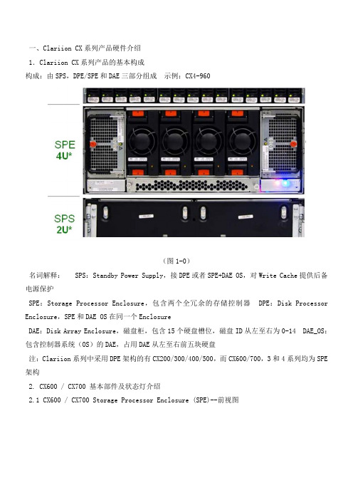
一、Clariion CX系列产品硬件介绍1.Clariion CX系列产品的基本构成构成:由SPS,DPE/SPE和DAE三部分组成示例:CX4-960(图1-0)名词解释: SPS:Standby Power Supply,接DPE或者SPE+DAE OS,对Write Cache提供后备电源保护SPE:Storage Processor Enclosure,包含两个全冗余的存储控制器 DPE:Disk Processor Enclosure,SPE和DAE OS在同一个EnclosureDAE:Disk Array Enclosure,磁盘柜,包含15个硬盘槽位,磁盘ID从左至右为0-14 DAE_OS:包含控制器系统(OS)的DAE,占用DAE从左至右前五块硬盘注:Clariion系列中采用DPE架构的有CX200/300/400/500,而CX600/700,3和4系列均为SPE 架构2. CX600 / CX700 基本部件及状态灯介绍2.1 CX600 / CX700 Storage Processor Enclosure (SPE)--前视图(图1-1)(1) 3个热插拔风扇模块(2) 风扇模块错误灯(黄灯亮表示有错误,在前面板上看不见,需拆下前面板才能看见) (3) SPE 电源指示灯(绿灯) SPE 错误指示灯 (黄灯)2.2 CX600 / CX700 Storage Processor Enclosure (SPE)--后视图(图1-2)(1) Storage Processors A(2) Storage Processors B(3) 2个热拔插电源模块 (active/active, 1+1)2.3 CX600 / CX700 Storage Processor (SP)—细节图(图1-2)(1) 4 个前端(连主机)2Gb FC 端口(每个 Storage Processor )(2) 4个后端(连扩展DAE)2Gb FC端口(每个 Storage Processor )(3) 10/100 局域网管理端口(4) SP Status LEDs--用于SP启动检测和检查SP的健康状态(5) Port80h Card--在SP主板上,用与开机自检,(6) SPS Monitoring Port--连接SPS的串口,用于SP与SPS之间的通讯和控制(7) Serial/PPP Port--获取动态IP地址进行维护或也可通过HyperTerminal软件检测SP的启动3. CX200 / 300 / 400 / 500 基本部件及状态灯介绍3.1 CX200 / 300 / 400 / 500 Disk Processor Enclosure (DPE)(四款产品均为DPE架构,除 SP的前端和后端端口数量有差别外,基本一样,下图为CX500的DPE)(图1-4)(1) BE0 –后端总线端口0(HSSDC)--连接DPE和DAE(2) BE1 –后端总线端口1(HSSDC)--连接DPE和DAE(3) 两个前端 2Gb 端口(FC) 每个Storage Processor(4) Enclosure 状态灯--绿色(电源灯),黄灯(错误灯或可用于检测启动过程)(5) 10/100 以太网管理端口(6) Serial Mgmt Port (RJ-45)--获取动态IP地址进行维护或也可通过HyperTerminal软件检测SP的启动(7) SPS Monitoring Port--连接SPS的串口,用于SP与SPS之间的通讯和控制4. CX3-10 / 3-20 / 3-40基本部件及状态灯介绍4.1 CX3-10 / 3-20 / 3-40 Storage Processor Enclosure (SPE)--前视图(图1-5)(A) 四个热插拔电源模块,从左至右依次为PS_A0 A1 B0 B1(B) 电源模块故障指示灯,故障时亮黄色(C) 系统电源指示灯:绿色,常亮系统故障指示灯:黄色,系统故障时亮4.2 CX3-10 / 3-20 / 3-40 Storage Processor Enclosure (SPE)—后视图(图1-6)4.3 CX3-10 / 3-20 / 3-40 Storage Processor (SP)—细节图(三款产品均为SPE架构,除 SP 前端和后端端口数量有差别外,基本一样,下图为CX3-40的SP)(图1-7)A:SPS监控端口B:管理串口C:电源指示灯:绿色,常亮D:故障指示灯:黄色,故障时亮E:服务管理网口F:客户管理网口G:后端扩展端口H:前端光纤端口5. CX3-80基本部件及状态灯介绍5.1 CX3-80 Storage Processor Enclosure (SPE)—前视图(图1-8)A:电源模块,上有黄色故障指示灯,故障时亮B:冷却风扇模块,上有黄色故障指示灯,故障时亮C:系统故障指示灯:黄色,故障时亮D:系统电源指示灯:绿色,常亮5.2 CX3-80 Storage Processor Enclosure (SPE)—后视图(图1-9)A:电源模块B:SAN Management ModuleC:I/O 模块电源模块5.3 CX3-80 Storage Processor (SP)—细节图(图1-10)A:SP控制器工作状态指示灯B:I/O Module5.4 CX3-80 I/O Module --细节图(图1-11)A:后端端口工作状态LEDB:后端端口C:前端端口D:前端端口工作状态LEDE:I/O模块电源与故障指示灯,黄色灯亮表示有故障5.5 CX3-80 SAN Management Module --细节图A:电源指示灯B:故障指示灯C:用户管理网络端口D:服务管理网络端口,仅限于EMC服务人员使用E:管理串口F:SPS监控端口(图1-12)6. CX4-120 / 240 / 480 基本部件及状态灯介绍6.1 CX4-120 / 240 / 480 Storage Processor Enclosure (SPE)—前视图(图1-13)A0:电源模块A1:电源模块B0:电源模块B1:电源模块C:CPU模块AD:CPU模块BE:CPU模块A电源和故障指示灯F:CPU模块B电源和故障指示灯G:存储系统电源和故障指示灯6.2 CX4-120 / 240 / 480 Storage Processor Enclosure (SPE)—后视图(图1-14)A:Management Module(管理模块)B:I/O Module(I/O模块)C:Power / Fault LED(电源/故障指示灯)6.3 CX4-120 / 240 / 480 Storage Processor (SP)—细节图(图1-15)A:Management Module(管理模块)B:Back End Port on I/O Module(I/O模块上的后端端口,连接DAE)C:FC Front End Port on I/O Module(I/O模块上的前端光纤端口,连接主机)D:iSCSI Front End Port on I/O Module(I/O模块上的前端iSCSI端口,连接主机)6.4 CX4-120 / 240 / 480 Management Module—细节图A:Service LAN Port(服务端口,仅限于EMC服务使用)B:Management LAN Port(用户管理端口)C:SPS Port(SPS监控端口)D:Communications Port(管理端口)E:NMI(系统维护用,勿触动)(图1-16)7. CX4-960基本部件及状态灯介绍7.1 CX4-960 Storage Processor Enclosure (SPE)—前视图(图1-17)A1:Power Supply A(电源模块A)A2:Power Supply B(电源模块B)B1-B4:Blowers / Fans(风扇模块)C:Enclosure Fault LED(系统故障指示灯)D:Power LED(系统电源指示灯)7.2 CX4-960 Storage Processor Enclosure (SPE)—后视图(图1-18)A:Power Supply B(电源模块B)B:Power Supply A(电源模块A)C:Management Module(管理模块)D:Management Module(管理模块)E:I/O Annex(I/O扩展模块)7.3 CX4-960 Storage Processor (SP)—细节图(图1-19)A:Power LED(电源指示灯)B:Fault LED(故障指示灯)C:Unsafe to Remove LED D1-D4:I/O Module(I/O模块)7.4 CX4-960 Management Module—细节图A:Fault LED(故障指示灯)B:Power LED(电源指示灯)C:USBD:Management LAN Port(以太网管理端口)E:Service LAN Port(以太网服务端口,仅限于EMC服务人员)F:NMI ButtonG:Communications Port(服务端口)H:SPS Port(SPS 监控端口)(图1-20)8. Disk Array Enclosure (DAE)基本部件及状态灯介绍8.1 Disk Array Enclosure (DAE) --前视图(图1-21)(10) 硬盘状态灯--绿灯表示连接状态,绿灯闪烁表示磁盘活动状态,黄灯亮表示磁盘报错 (11) 盘柜状态灯--绿灯表示供电正常,黄灯亮表示盘柜有错误(12) Slot0-4 ,共5块DAE-OS Vault Drives (仅限于DAE_OS),从左至右,Slot 0--Slot4 8.2 Disk Array Enclosure (DAE) --后视图(图1-22)Two Link Control Card (LCC)(1) LCC 状态灯--绿色表示电源,黄色表示有错误(2) Expansion 端口(HSSDC)--灯亮表示有信号(3) 光纤环路ID指示灯( Loop ID LED)--0,1,2,3, 表示后端连接的光纤换路(Loop) ID (4) Primary 端口(HSSDC)--灯亮表示有信号 Two DAE电源模块(5) 两个集成了风扇的电源模块(6) 风扇错误灯(黄色)(7) 电源状态灯(绿色--有电,黄色--有错)(8) 交流电源输入开关,对DAE-OS,DPE或SPE关电,应使用此开关(9) Enclosure 地址开关-如是DAE-OS的Enclosure,则其必须被设置为08.3 Disk Array Enclosure 2P/3P (DAE 2P/3P) --后视图(图1-23)A:电源模块,下面电源模块为PS A,上面为PS BB:LCC模块,下为LCC A,上为LCC BC:PRI端口,连接SP Back End端口或者上级DAE EXP端口D:EXP端口,连接下级DAE PRI端口E:Enclosure ID LED F:Loop ID LEDG:电源与故障指示灯9. Standby Power Supply (SPS) 基本部件及状态灯介绍9.1 1 KW I U SPS(图1-24)(1) 电源开关(2) 交流电源输入(3) SPE & 启动盘所在DAE的交流输出(4) SPS 监测端口--连接SP的串口,用于SP与SPS之间的通讯和控制(5) 状态灯 (从下至上)内部监测灯—亮黄色表示SPS内部监测出错更换SPS指示灯—亮黄色表示电池寿命已到或者自检出错电池供电指示灯--当SPS给SP或DAE OS供电时亮黄色电源灯--当SPS充满电后亮常绿,当SPS电池被充电时闪绿色9.2 2.2KW 2U SPS(图1-25)A:交流输入B:交流输出C:电源开关D:SPS监测端口--连接SP的串口,用于SP与SPS之间的通讯和控制E:状态灯(从下至上)内部监测灯—亮黄色表示SPS内部监测出错更换SPS指示灯—亮黄色表示电池寿命已到或者自检出错电池供电指示灯--当SPS给SP或DAE OS供电时亮黄色电源灯--当SPS充满电后亮常绿,当SPS电池被充电时闪绿色二、如何用 Navisphere看存储的状态在 Navisphere 中,除正常状态以外,CX 磁盘阵列的四种常见状态T:一个或者多个部件处于Transition状态,比如LUN正在Rebuilding,SPS正在充电 F:一个或者多个部件出现故障,注意,存储刚加电,由于SPS充电,也会出现F状态X:存储系统不可访问,比如网络连接断开等情况?:当前Navishper版本不支持对该存储系统进行管理举例如下:Array in TransitionArray FaultedArray Inaccessible如在 Navisphere 发现有报错,检查 CX磁盘阵列错误的简单方法1、右击存储,选择fault,会显示具体报错信息2、展开Physical项,可以定位具体故障部件3、Clariion每个部件都有独立的故障指示灯,在Navishpere发现错误后,可以观察存储故障部件的错误指示灯进一步确认三、客户发现 Clariion出现问题,应如何报修?(注:如客户已装了 dial-out或者Call-home, 存储会让管理工作站自动拨号并报修,若无,需客户自己发现并报修)1.获取 Clariion CX系列阵列的序列号有以下五种方法:方法一:EMC 工程师在存储安装时会在存储贴上写有序列号的白色标签,标签上会注明客户EMC报修电话、Site ID 、存储序列号等信息,参见下图:方法二:如安装工程师漏贴标签,注意必须查SPE或DPE上的标签(DPE架构的从机柜后面查看上图所示位置)(SPE架构的从机柜正面拆下SPE挡板,查看上图所示位置)方法三:通过serialization tag查看(仅适用于Clariion 4系列产品) CX4-120/240/480请查看存储SPE后部的黑色标签,上面有产品的PN(型号),SN(序列号)CX4-960 和CX4-120/240/480差不多,也是在SPE后部有一个黑色标签,只是位置不同方法四:通过 Navisphere命令查看 CX存储的序列号:(红色字体)C:\Program Files\EMC\Navisphere CLI>navicli -h 192.168.2.164 getagentName: K10 Desc:Node: A-CK200072300124Physical Node: K10Signature: 1912950Peer Signature: 1912955SCSI Id: 0SP Identifier: ARevision: 3.26.40.5.016Model: CX3-40cModel Type: RackmountProm Rev: 3.58.00SP Memory: 4096Serial No: CK200072300124Cabinet: SPE3 C:\Program Files\EMC\Navisphere CLI>方法五:通过 Navisphere图形界面查看 CX存储的序列号右击存储,选择Properties,在弹出窗口General选项卡中的Serial Number一项2.拔打 EMC 全球响应中心 800电话报修如用固定电话报修,请拔打 8008190009如用手机报修,请拔打4006700009 请依照语音提示进行报修注意:必须事先准备好序列号,报修时需提供存储序列号( CX系列的序列号格式基本都是 CK2000开头,后跟 8位数字),同时请提供具体的故障描述,如果部件故障,最好能提供故障部件的Part Number(PN),特别是硬盘的PN,以便于服务人员准确准备备件四、EMC Clariion CX系列开关机注意事项及详细步骤开机前注意事项:1. 磁盘阵列在加电前,为确保磁盘柜散热和工作正常,请确认所有磁盘柜的每个槽位都已经插上硬盘和挡风板2. 开机前需确保――SPE或 DPE至少要有一个正常工作的 SP,每个 DAE都至少要一块正常工作的 LCC1. 检查所有供电线路联接是否正常,是否有松动或改动并改正2. 从机柜顶部开始,由上至下打开所有 DAE磁盘机箱的电源。
EMC CX3-10C 安装配置手册
EMC CX3-10C 安装配置手册目录第一部分、系统实施拓扑图 (3)第二部分、MC CX3-10C设备安装 (3)2.1、设备上架 (3)2.2、数据线的连接 (4)2.3、电源线的连接 (5)第三部分、服务器及存储SP IP地址 (5)第四部分、服务器安装 (6)4.1、服务器操作系统升级 (6)4.2、安装HBA卡及驱动 (6)4.3、安装N A VISPHERE SERVER UTILITY (7)4.3、安装P OWERPATH (13)第五部分、EMC CX3-10C配置 (14)5.1、安装初始化工具 (14)5.2、初始化CX3-10C存储系统 (20)5.3、配置CX3-10C存储系统 (26)5.3.1、设置Hot Spare (29)5.3.2、创建RAID Group (34)5.3.3、在RAID Group创建LUN (39)5.3.4、创建Storage Groups 并连接主机 (45)第一部分、系统实施拓扑图XXX网站社区版服务器及存储系统实施拓扑图如下:第二部分、MC CX3-10c设备安装2.1、设备上架EMC CX3-10c的上架安装参见:“附件:CX3-10 现场安装指南”。
第三部分、服务器及存储SP IP地址第四部分、服务器安装4.1、服务器操作系统升级各个服务器安装最新补丁,确保EMC软件能够进行安装。
Windows Server 2003至少需要sp1补丁。
4.2、安装HBA卡及驱动安装顺序如下:安装操作系统Windows server 2003 打SP1补丁(至少),关机后,安装HBA卡,装完开机如图:可以找到HBA卡,安装HBA卡驱动后如下图:4.3、安装Navisphere server utility 双击“Navisphere Server Utility (Windows)”点击“Next”点击“Next”按默认,点击“Next”点击“”Next点击“Next”点击“Install”点击“No”不安装iscsi initiator点击“Done”4.3、安装Powerpath选择否在安装最后一步输入License。
使用维护手册

EMC CLARiiON使用维护手册第一章系统日常使用规范1环境需求空气质量EMC设备须安装于空调环境中,空气的温度及湿度均可调节;如从室外补充新风,需经滤网过滤,以保证空气的洁净度。
机房温度湿度机房高度对于EMC CLARiiON CX3系统,从活动地板至天花板或吊顶的最小高度为250cm.水平高度重量设备重量因设备型号,配置的不同及产品的改进而有所不同,变化范围很大。
下表仅供活动地板活动地板必须能够支撑设备的重量,包括静态单点承重及动态移动承重。
如果地板不够,地板的四角必须有坚固立柱支撑。
对于超过500公斤存储系统的安装,除满足上述要求外,承重地板需进行额外加固,在每块承重地板的中央另加立柱支撑静态单点承重静态单点承重的计算方法是:设备满配置重量(最大重量)÷承重点数量所有EMC存储设备均有4个滚轮,因此活动地板的静态单点承重=设备满配置重量÷ 4动态移动承重态移动承重是指设备移动时地板承受的重量动态移动承重的计算方法是:设备重量÷承重点数量除上述设备重量外,用户应根据自己的实际情况,考虑周围设备及人员活动情况,综合计算地板的承重电源容量的开关,以防止当某一相电源跳闸时,带动另外两相电源同时跳闸。
2管理设备为了更好的对盘阵状态进行监控,要求在机房内安装一台预装Win2000 的PC并与机房网络连接。
该PC 同时要求预装JRE 1.4。
3注意事项为确保数据高可用性及安全,我公司对所有销售的EMC CLARiiON 系列产品均有完善周到的售后服务,因此在设备出现硬件故障时,希望客户及时与我们联系。
如因特殊原因需客户自行进行硬件更换,必须在远程监控下完成。
同时光纤线不能被挤压,踩踏,折角不能超过90度。
所有的备用盘均应避免震动。
第二章系统启动和停止系统启动1.开启机柜电源2.开启所有与CX3-40连接的DAE电源3.开启CX3-40风扇电源模块电源4.开启SPS电源开关5.加载应用系统关闭1.停止主机所有对盘阵的I/O2.如果应用系统是UNIX OS 要Umount file systems3.关闭SPS电源4.在SPS电源关闭后,将所有的DAE电源开关置于关闭状态5.将机柜电源关闭第三章日常监控监控工具EMC CLARiiON CX3-40可以通过EMC公司Navisphere Manager软件进行日常监控,Navisphere Manager 可以安装在Windows 2000/NT/XP 平台上,可以通过网络对盘阵进行日常监控。
EMC设备配置操作说明
EMC系统操作手册EMC光纤交换机、磁盘阵列操作手册设备型号:DS_300B&EMC CX-4 240承建单位:宁夏希望信息产业有限公司监理单位:深圳市东方天成管理顾问有限公司建设单位:宁夏医科大学附属医院编写日期:二零一零年一月目录1.1 EMC DS_300B_A (3)1.2 定义zone (4)2.1 EMC DS_300B_B (7)2.2 定义zone (8)3.1 EMC B300_B 配置信息 (11)4.1 EMC CX-4 240 配置信息 (16)4.2 初始化阵列系统 (16)4.3 阵列的设置 (20)4.4 主机软件安装和配置 (29)5.1 端口对照表 (34)1.1 EMC DS_300B_A在浏览器的地址栏里输入EMC DS_300B的默认ip地址10.77.77.77,用户名admin,密码password,定义本机的管理地址为10.0.11.63,管理机器名称为DS_300B_A,定义完毕后信息如下根据Manufacturer serial number ALJ0634E06B;Supplier serial number BRCALJ0634E06B;上网注册得到的License ID,激活8-15端口。
由图中可以看出,前面16个端口为深灰色可用状态。
1.2 定义zone定义zone,在zone admin 界面下定义Zone1,根据DS_300B_A端口对照表,将交换机的0,1,2端口加入到zone1当中,然后保存启动zone1,配置信息如下将交换机的0,1,3端口加入到zone2当中,然后保存启动zone2将交换机的0,1,4端口加入到zone3当中,然后保存启动zone3。
在交换机名称定义里,填入DS_300B_A,交换机信息如下修改交换机的默认管理地址为10.0.11.63,网关定义为10.0.11.1,以方便在网络中进行管理。
交换机许可信息如下,由下图可以看出总共激活16个端口。
EMC CX系列磁阵安装与维护手册
3. 连接成功后,打开一个网页,地址栏输入192.168.1.1/setup后,回车. 4. 此时回出现类似下图的界面:
l. 确认 Enable LCP extensions and Enable software compression 被激活, 然后点 击 OK.
m. 选中 Internet Protocol (TCP/IP) 后设置属性. 设置自动获取IP地址,DNS服务器地址. 相关参数设置表如下:
Line characteristic 设置
users and click Next.
f. 在 Completing Network Connection Wizard 对话框里, 给 此连接起 个名字 (例如, CX 系列 init)然后选择 Finish.
g. 在 Connect 对话框中点击 Properties.
h. 在 Properties 栏的 General 栏中, 点击 Configure.
七、 使用 Manager (Rev. 6.x) 创建 STORAGE GROUP
在 Navisphere 6.x 下, 通过以下步骤创建 storage group: a. 鼠标右击 storage-system 图标, 然后选择 Create Storage Groups.
b. 为此 Storage Group 创建一个新名字.
重要提示: 同一个 RAID 组的的所有磁盘必须是相同容量的的同等规格的磁盘. 而 hot
spare 盘必须大于或等于磁盘阵列中所有硬盘的容量. 3.被选的磁盘会呈现出来以供选择
Dell EMC CX3-Series iSCSI 存储阵列使用 Microsoft Windows
使用 Microsoft ® Windows Server ® 故障转移群集的 Dell|EMC CX3-Series iSCSI 存储阵列 硬件安装与故障排除指南简介群集硬件的布线准备用于群集的系统故障排除iSCSI 配置工作表群集数据表注、注意和警告本说明文件中的信息如有更改,恕不另行通知。
© 2008 Dell Inc. 版权所有,翻印必究。
未经 Dell Inc. 书面许可,严禁以任何形式复制这些材料。
本文中使用的商标;Dell 、DELL 徽标、PowerEdge 、PowerVault 是 Dell Inc 的商标;Active Directory 、Microsoft 、Windows 、Windows Server 、Windows XP 和 Windows NT 是 MicrosoftCorporation 在美国和/或其它国家和地区的商标或注册商标;EMC 、Navisphere 和 PowerPath 是 EMC Corporation 的注册商标,而 Access Logix 、MirrorView 、SAN Copy 和 SnapView 是 EMC 的商标。
本说明文件中述及的其它商标和产品名称是指拥有相应商标和产品名称的公司或其制造的产品。
Dell Inc. 对本公司的商标和产品名称之外的其它商标和产品名称不拥有任何专有权。
2008 年 7 月 Rev. A00注: "注"表示可以帮助您更好地使用计算机的重要信息。
注意: "注意"表示可能会损坏硬件或导致数据丢失,并告诉您如何避免此类问题。
警告: "警告"表示可能会导致财产损失、人身伤害甚至死亡。
返回目录页面群集硬件的布线使用 Microsoft ® Windows Server ® 故障转移群集的 Dell|EMC CX3-Series iSCSI 存储阵列 硬件安装与故障排除指南鼠标、键盘和显示器的布线电源设备的布线公用网络和专用网络的群集布线存储系统的布线鼠标、键盘和显示器的布线在机架中安装群集配置时,必须安装开关盒,以将鼠标、键盘和显示器连接至节点。
EMC CX系列安装及配置

• not allowed. Examples: Array1-A, Array1-B.
• IP Address _______________ _______________
• Subnet Mask _______________ ______________
• Gateway _______________ ______________
EMC CLARiiON 安装及配置
CLARiiON安装配置
1. Gather Network Information 2. Verify Power Supply Settings 3. Confirm the Standby Power Supply(SPS) Connections 4. Start The FC4700 5. Initialize the FC4700 6. Connect a Management Station 7. Configure The t Connections 9. Setup The Hosts 10. Creat The FC4700 Storage Group 11. Complete The Host Setup 12. Setup SnapView And MirrorView SoftWare 13. Setup Event Monitor
4. Verify that the Standby Power Supplies (SPSs), Disk Processor Enclosure (DPE), and any optional Disk Array Enclosures(DAEs) are installed in your cabinet. If necessary, refer to the appropriate cabinet, rail, or device hardware installation documentation you received with your system.
CX3_20(emc)配置管理手册
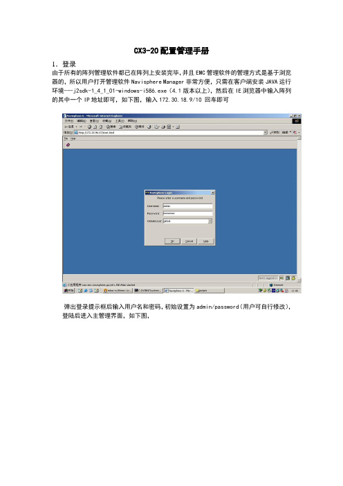
CX3-20配置管理手册1.登录由于所有的阵列管理软件都已在阵列上安装完毕,并且EMC管理软件的管理方式是基于浏览器的,所以用户打开管理软件Navisphere Manager非常方便,只需在客户端安装JAVA运行环境---j2sdk-1_4_1_01-windows-i586.exe(4.1版本以上),然后在IE浏览器中输入阵列的其中一个IP地址即可,如下图,输入172.30.18.9/10 回车即可弹出登录提示框后输入用户名和密码,初始设置为admin/password(用户可自行修改),登陆后进入主管理界面,如下图,3.监控、浏览硬件状态打开管理界面后,用户可详细地了解到阵列上的硬件配置以及他们的状态信息,这其中的硬件包括硬盘、风扇、电源模块、电池、处理单元等等,如下图,打开Physical的树状节点即可。
4.添加、删除、修改用户和密码EMC在用户管理这一块提供了多种角色,主要分为Administrator 和Monitor,Administrator 有权利对阵列进行配置、属性修改等活动,而Monitor只能对阵列进行监控浏览。
用户可根据需要创建不同的用户。
如下图打开用户管理界面打开以后,如下图,进行用户的添加如下图,进行用户密码的修改修改完毕后退出重新登陆即可。
5.浏览、修改阵列属性阵列上有几个Cache参数由于涉及到性能问题,而且同客户的应用息息相关,所以,有必要在属性端调整一下读写Cache的大小,如下图,打开CX3-20的属性页在改变Cache的大小前先将SPA、SPB的读写Cache置成disable,如下图根据应用对读写的要求重新分配读写Cache的大小,如下图修改完以后,重新在将SPA、SPB的读写Cache置成enable,如下图6.浏览阵列于主机的连接信息在阵列连接主机前,我们有必要先观察一下主机的HBA卡是否已经注册到阵列端,一般主机在安装完HBA卡驱动,并安装好Navisphere Agent后,HBA卡信息会自动注册到阵列上,如下图打开连接状态页面如下图,察看连接状况其中Login属性,表示物理连接正常,Register属性表示注册成功。
EMC CX系列磁盘阵列配置
目录1、安装光纤通道卡及其驱动 (2)2、安装服务器主机代理软件 (2)2.1 Linux系统 (2)2.1.1 将Agent软件上传到linux主机中 (2)2.1.2 安装Agent软件 (2)2.1.3 修改Agent配置文件 (2)2.1.4 启动Agent服务 (3)2.2 Windows系统 (3)2.2.1 软件包 (3)2.2.2 软件包安装 (3)3、安装Powerpath多路径管理软件 (6)3.1 Liunx 系统 (6)3.1.1 将Powerpath软件上传到linux主机中 (6)3.1.2 安装Powerpath软件 (6)3.1.3 Powerpath软件注册 (7)3.1.4 系统重启查看状态 (7)3.2 Windows 系统 (8)3.2.1 软件包 (8)3.2.2 软件包安装 (8)4、光纤交换机管理 (11)4.1 光纤交换机基本配置 (11)4.2 光纤交换机基本命令行管理 (12)4.3 光纤交换机连接拓扑 (15)4.4 光纤交换机图形化配置(WEB UI) (15)5、磁盘阵列配置 (17)5.1 磁盘阵列基本管理 (17)5.2 LUN建立 (18)5.3 建立存储组 (19)5.4 主机注册 (20)5.5 建立主机与LUN关联(主机挂载磁盘) (21)1、安装光纤通道卡及其驱动在服务器上安装好光纤通道卡,建议安装新版本的驱动。
驱动程序查看HBA卡芯片后,去相关网站可以下载到对应操作系统的驱动程序。
2、安装服务器主机代理软件2.1 Linux系统2.1.1 将Agent软件上传到linux主机中上传的文件为”naviagentcli-6.26.30.0.99-1.noarch.rpm”2.1.2 安装Agent软件[root@DB01 ~]# rpm –ivh naviagentcli-6.26.30.0.99-1.noarch.rpm Preparing... ########################################### [100%]1:NaviHostAgent-Linux-########################################### [100%]2.1.3 修改Agent配置文件[root@DB01 ~]# emcsoft]# vi /etc/Navisphere/agent.config############################ Navisphere agent.config###########################user system@172.16.0.251 /需要添加的user system@172.16.0.252 /需要添加的注意:地址为磁盘阵列的两个控制器的管理地址2.1.4 启动Agent服务/etc/init.d/naviagent start注:可以等安装完多路径管理软件后一起重启系统。
emc cx 320
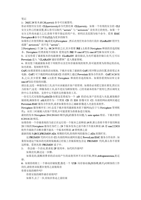
笔记1:26(02.26版本,03.26),navicli命令可以被禁用。
你必须使用安全的CLI(naviseccli)命令代替经典CLI(navicli)。
如果一个有效的安全的CLI 安全文件已经被设置,那么你可以取代“navicli”与“naviseccli”没有其它的变化。
如果一个安全文件尚未建立之后,你将不得不指定的用户名、密码以及范围为每个命令。
看到EMC Navisphere®命令行界面(CLI)为更多的细节.如果你正在使用释放26(或更高)Navisphere ,然后改变任何命令的片段在CLARiiON程序生成器”naviseccli”而不是“navicli”。
2:Navisphere(1月26日)、06.26释放之后,至少需要JRE 1.5;检查Navisphere释放的首选的版本。
Navisphere经理表现不同版本-看到这些JRE和emc167251 emc167250知识库文章。
3:证实你看了最新版本的电磁兼容CLARiiON最佳做法,为光纤通道存储白皮书,它可以Powerlink进入“CLARiiON最好的惯例”进入搜索领域。
4:核实您下载最新版本的下列软件以及任何存储系统的软件,你可能需要为你预定的活动,如光斑束、复制软件等等。
CAP2:如果需要你去做的活动现场。
下载并安装了最新的CAP2程序默认的位置,你的笔记本电脑。
CAP2可下载的网站或电磁CS内部网上通过Powerlink服务合作伙伴。
CAP2 6.26版本,之后,至少需要JRE 1.5;检查Navisphere释放的首选的版本。
如果你看到知识库文章emc167252经验的问题。
请注意,这是一种服务的工具,而不应该被放在客户的管理。
如果你必须把它留在那里,然后压力给客户,这是一种服务的工具,而不是仅为顾客使用。
已经有副本的客户使用它,然后调用支持中心寻求帮助。
支持中心不提供支持服务的工具。
一份交互式安装指南(iiG)CD:如果这是要成为一个iiG的活动,客户没有进入光盘,被装载存储系统,确保你有iiG,或者作为一个焚烧CD的ISO影像可在CS内部的网站或网页通过Powerlink EMC服务合作伙伴,或者如果你有自己ISO影像进入光盘仿真软件。
EMC存储配置手册

1CLARiiON初级安装使用Navisphere Storage System Initialization Wizard初始化第一次安装时需要使用Navisphere Storage System Initialization Wizard工具。
打开该工具。
接受License Agreement后点击Next继续点击Next系统将扫描存在的存储系统选择需要配置的存储系统,然后输入SP A和SP B的IP地址创建用户名和密码,默认用户名:admin 密码:password完成CX3-40的初始化这样CX3-40的初始化就完成了。
下次只需要通过浏览器输入SP的IP地址就可以直接登录。
登陆WEB管理界面:在地址栏输入存储的IP地址,键入用户名和密码(地址默认为10.10.10.198)输入用户名和密码(admin/password)1.1基本配置1.划分Raid Group右击数组,选择“Create RAID Group”可以选择RG的ID号,然后在Disk Selection里选择Manual,然后点击Select,手工指定需要划分的硬盘选择A vailiable Disks里需要的磁盘,划到右侧Selected Disks里点击OK根据提示点击Y es2.创建资料LUN右击数组,选择Bind LUN选择需要bind lun的raid group,这里选择raid group 3为新bind的lun分配一个LUN ID,这里分配LUN 21选择LUN属于哪个SP,这里属于SP B在LUN Size中填入LUN的大小,这里的LUN是10GB,然后点击Apply按照提示点击Y es继续点击OK完成查看LUN 21的属性,看到LUN 21的大小是10GB,Percent Bound是100,说明LUN 21已经Bind完成,可以分配给主机访问使用了3.创建Hot Spare右击准备需要创建的Hot Spare的Raid Group,选择Bind LUN在Raid Type中,选择Hot Spare选项然后分配LUN ID(一盘hotsapre的id分配的大点,以便于和数据lun区分),最后点击Apply 确定。
emcvnx配置手册

第1章文档目录第1章VNX5400 硬件部分 ................................................................... 错误!未定义书签。
1.1.硬件部分: (4)1.2.设备基本信息 (4)1.2.1.开机注意事项 (4)1.2.2.开机环节 (5)1.2.3.关机前注意事项 (5)1.3.使用UNISPHERE进行配置 (6)1.3.1.登陆到管理界面 (6)1.3.2.创立Raid Group (12)1.3.3.创立LUN ............................................................................... 错误!未定义书签。
1.3.4.创立Storage Group ............................................................... 错误!未定义书签。
1.3.5.注册主机 ................................................................................ 错误!未定义书签。
1.3.6指派LUN ............................................................................... 错误!未定义书签。
1.3.7指派主机 ................................................................................ 错误!未定义书签。
1.3.7创立Mirror ............................................................................. 错误!未定义书签。
- 1、下载文档前请自行甄别文档内容的完整性,平台不提供额外的编辑、内容补充、找答案等附加服务。
- 2、"仅部分预览"的文档,不可在线预览部分如存在完整性等问题,可反馈申请退款(可完整预览的文档不适用该条件!)。
- 3、如文档侵犯您的权益,请联系客服反馈,我们会尽快为您处理(人工客服工作时间:9:00-18:30)。
3.监控、浏览硬件状态
打开管理界面后,用户可详细地了解到阵列上的硬件配置以及他们的状态信息,这其中的硬件包括硬盘、风扇、电源模块、电池、处理单元等等,如下图,打开Physical的树状节点即可。
填写相应的LUN信息,选择Raid类型,LUN大小,所属SP
配置完,提交即可
点击OK
如下图,生成如下的lun
绑定一个HotSpare盘如下,只要在Raid Type中选择Hot Spare 即可
9.创建Storage Group
建完LUN以后,需要建立主机和LUN之间的对应关系,使主机能访问到相应的LUN,如下图,创建一个Storage Group,
如下图,察看连接状况
其中Login属性,表示物理连接正常,Register属性表示注册成功。
7.创建Raid Group
所有这些前期工作做完以后,我们开始进行存储的划分,首先第一步进行Raid Group的划分,如下图打开界面,
打开后进行硬盘的划分,
8.创建LUN
当Raid Group配置完毕以后,我们开始在Raid Group 上划分LUN(根据阵列配置文档),打开LUN的配置界面,如下图,
根据应用对读写的要求重新分配读写Cache的大小,如下图
修改完以后,重新在将SPA、SPB的读写Cache置成enable,如下图
6.浏览阵列于主机的连接信息
在阵列连接主机前,我们有必要先观察一下主机的HBA卡是否已经注册到阵列端,一般主机在安装完HBA卡驱动,并安装好Navisphere Agent后,HBA卡信息会自动注册到阵列上,如下图打开连接状态页面
CX3-20配置管理手册
1.登录
由于所有的阵列管理软件都已在阵列上安装完毕,并且EMC管理软件的管理方式是基于浏览器的,所以用户打开管理软件Navisphere Manager非常方便,只需在客户端安装JAVA运行环境---j2sdk-1_4_1_01-windows-i586.exe(4.1版本以上),然后在IE浏览器中输入阵列的其中一个IP地址即可,如下图,输入172. 回车即可
打开以后,填写相应的Storage Group名,一般以主机名来识别
点击OK 即可
如下图,Strage Group 创建以后
创建Storage Group后,将主机和相应的lun划入到同一个Storage Group中
如下图,将左边的lun 加入到右边的框中
如下图,将左边的主机加入到右边的框中
配置完以后,如下图,相应的主机就只能访问到该StorageGroup下对应的LUN
4.添加、删除、修改户和密码
EMC在用户管理这一块提供了多种角色,主要分为Administrator和Monitor,Administrator有权利对阵列进行配置、属性修改等活动,而Monitor只能对阵列进行监控浏览。用户可根据需要创建不同的用户。如下图打开用户管理界面
打开以后,如下图,进行用户的添加
11.察看阵列日志
如下图,察看sp的日志信息
打开以后,可浏览事件,也可保存下来,如下图
10.一些日常问题的解决
a.日常点检主要为:
EMC的日志信息-- 见CX3-20配置管理手册
光纤通道交换机的状态信息 --- 见光纤通道交换机配置手册
b.如有硬盘发生故障,硬盘灯亮橘黄色的灯时,只须及时通知我们,请勿关闭阵列或插拔硬盘。
c.若某个光纤模块发生故障,光纤模块灯亮橘黄色的灯,只需要将该模块上的光纤线移到该交换机上空闲的模块上,然后通知我们进行模块的保修,整个过程不会影响应用和数据的读写访问。
d.若CX3-20上映射到主机上的硬盘突然访问不到,请切断应用,然后环境允许的话重启主机,然后通知我们,进行故障的诊断。
如下图,进行用户密码的修改
修改完毕后退出重新登陆即可。
5.浏览、修改阵列属性
阵列上有几个Cache参数由于涉及到性能问题,而且同客户的应用息息相关,所以,有必要在属性端调整一下读写Cache的大小,如下图,打开CX3-20的属性页
在改变Cache的大小前先将SPA、SPB的读写Cache置成disable,如下图