WTN4系列语音芯片说明书资料V1.05
WTV语音芯片外挂serial FLASH 方案推介手册-V1.04
7.1 应用电路重要提示--------------------------------------------------------18
7.2 模块外部接口框图---------------------------------------------------------18
7.3 模块原理图---------------------------------------------------------------18
模拟电源正极
数字地线
模拟地线
数字电源正极
PWM 输出口 1
7
Rev1.03 2007/4/10
4.2 模块外部接口描述
管脚号 1 2 3 4 5 6 7 8 9 10 11 12 13 14 15 16
名称 REST AUDIO SP+
SPDI DO CLK GND CS P03 P02 01 P00 NC BUSY VCC
¾ 多种工作模式:按键控制模式、按键组合控制模式、并口控制模式、串口控制模式等,可任意设置成其
中一种.播放语音时,BUSY脚可根据需要,设定输出高电平或低电平
¾ 内置0.5W喇叭直推线路(Direct-Drive),不需要外加器件,音质与音量比传统"Cout+三极管"更佳,且耗电量更
少
¾ 工作电压范围:2.5V至3.5V, 省电模式时耗电 2 uA
2.简介---------------------------------------------------------------------------5
3. 主控 IC 内部框图----------------------------------------------------------------6
TWN4 MultiTech SmartCard user 说明书

TWN4 MULTITECH SMARTCARDTWN4 SmartCard MIFARE NFC USBUSER MANUALTABLE OF CONTENTS1INTRODUCTION (3)1.1ABOUT THIS MANUAL (3)1.2SCOPE OF DELIVERY (3)1.2.1COMPONENTS AND ACCESSORIES (3)1.2.2SOFTWARE (3)1.3ELATEC SUPPORT (3)1.4REVISION HISTORY (3)2INTENDED USE (4)3SAFETY INFORMATION (5)4TECHNICAL DATA (7)5MODE OF OPERATION (8)5.1OPERATING MODE (8)5.2POWER UP (8)5.3ENUMERATION (8)5.4INITIALIZATION (8)5.5NORMAL OPERATION (8)5.6DETECTION OF A TRANSPONDER (8)5.7SUSPEND MODE (9)6COMPLIANCE STATEMENTS (10)6.1EU (10)6.2FCC (10)6.3IC (10)6.4RF EXPOSURE COMPLIANCE (11)6.5CHINA (PRC) (11)6.6UNITED KINGDOM (12)6.7FURTHER STATEMENTS (12)6.7.1BRAZIL (12)6.7.2MEXICO (13)6.7.3TAIWAN (ROC) (13)6.7.4THAILAND (13)APPENDIX (14)A – TERMS AND ABBREVIATIONS (14)B – RELEVANT DOCUMENTATION (14)1INTRODUCTION1.1ABOUT THIS MANUALThis user manual is intended for the user and enables a safe and appropriate handling of the product. It gives a general overview, as well as important technical data and safety information about the product. Before using the product, the user should read and understand the content of this user manual.For the sake of better understanding and readability, this user manual might contain exemplary pictures, drawings and other illustrations. Depending on your product configuration, these pictures might differ from the actual design of your product.The original version of this user manual has been written in English. Wherever the user manual is available in another language, it is considered as a translation of the original document for information purposes only. In case of discrepancy, the original version in English will prevail.1.2SCOPE OF DELIVERY1.2.1COMPONENTS AND ACCESSORIESDepending on your product configuration, the product can be delivered alone or with different components and accessories, such as cables or wall holders, as part of a kit. For more information about the delivered components and accessories, refer to your delivery note, consult the ELATEC website or contact ELATEC.1.2.2SOFTWAREThe product is delivered ex-works with a specific software version (firmware). Refer to the label attached to the product to find the software version installed ex-works.1.3ELATEC SUPPORTIn case of any technical questions, refer to the ELATEC website () or contact ELATEC technical support at***********************In case of questions regarding your product order, contact your Sales representative or ELATEC customer service at********************1.4REVISION HISTORYVERSION CHANGE DESCRIPTION EDITION edition 03/2022 01 First2INTENDED USEELATEC TWN4 MultiTech SmartCard is a combination of the TWN4 MultiTech (RFID) with an integrated contact card reader/writer (ISO 7816). It allows users to read and write almost any 125 kHz and 13.56 MHz transponders supporting all major technologies from various suppliers like ATMEL, EM, ST, NXP, TI, HID, LEGIC, etc. and many ISO standards such as ISO 14443A/B (T=CL), ISO 15693 and ISO 18092 / ECMA-340 (NFC). The integrated chip card reader is designed for easy integration into various applications.The product is for indoor use and may not be used outdoor.Any use other than the intended use described in this section, as well as any failure to comply with the safety information given in this document, is considered improper use. ELATEC excludes any liability in case of improper use or faulty product installation.3SAFETY INFORMATIONUnpacking and installation∙The product contains sensitive electronic components that require particular attention when unpacking and handling the product.Unpack the product carefully and do not touch any sensitive components on the product.In case the product is equipped with a cable, do not twist or pull the cable.∙The product is an electronic product whose installation requires specific skills and expertise.The installation of the product should be done by a trained and qualified personnel only.Do not install the product by yourself.Handling∙Depending on your product configuration, the product might be equipped with one or more light-emitting diodes (LED).Avoid direct eye contact with the blinking or steady light of the light-emitting diodes.∙The product has been designed for a use under specific conditions (refer to the product data sheet).Any use of the product under different conditions might damage the product or alter its reading performance.∙The use of other RFID readers or reader modules in direct vicinity to the product, or in combination with the product might damage the product or alter its reading performance. In case of doubts, contact ELATEC for more information.∙The user is liable for the use of spare parts or accessories other than the ones sold or recommended by ELATEC.ELATEC excludes any liability for damages or injuries resulting from the use of spare parts or accessories other than the ones sold or recommended by ELATEC.∙Like most electronic devices, RFID systems generate electromagnetic waves that can vary in amplitude and frequency. It is generally known and accepted that some RFID devices might potentially interfere with personal medical devices, like pacemakers or hearing aids.Users with a pacemaker or any other medical device should use TWN4 MultiTech SmartCard carefully and refer to the information given by the manufacturer of their medical devices before using TWN4 MultiTech SmartCard. Maintenance and cleaning∙Any repair or maintenance work should be done by a trained and qualified personnel only.Do not try to repair or carry out any maintenance work on the product by yourself.Do not allow any repair or maintenance work on the product by an unqualified or unauthorized third party.∙The product does not need any special cleaning. However, the housing may be carefully cleaned up with a soft, dry cloth and a non-aggressive or non-halogenated cleaning agent on the outer surface only.Make sure that the used cloth and cleaning agent do not damage the product or its components (e.g. label(s)). Disposal∙The product must be disposed of in accordance with the EU directive on waste electrical and electronic equipment (WEEE) or any applicable local regulations.Product modifications∙The product has been designed, manufactured and certified as defined by ELATEC.Any product modification without prior written approval from ELATEC is prohibited and considered improper use of the product. Unauthorized product modifications may also result in the loss of product certifications.If you are unsure about any part of the safety information above, contact ELATEC support.Any failure to comply with the safety information given in this document is considered improper use. ELATEC excludes any liability incase of improper use or faulty product installation.4TECHNICAL DATAPower supply4.3 V -5.5 V via USBSmartCardsSupported SmartCards: 5V, 3V and 1.8V, ISO/IEC 7816 Class A/B/CPower to SmartCard: 60 mA in Class A; 55 mA in Class B; 35 mA in Class C AntennasThe reader is equipped with the following antennas:PCB contained in TWN4 MultiTech SmartCard HF antenna (13.56 MHz)Dimensions: 45 x 48 mm / 1.77 x 1.89 inchNumber of turns: 3LF antenna (125 kHz)Dimensions: 31 x 32 mm / 1.22 x 1.26 inchNumber of turns: 155For more information, refer to the related product data sheet or other technical documents.5MODE OF OPERATIONThe mode of operation described in the following chapter is based on a standard ELATEC RFID reader equipped with two LEDs. Depending on your product (number of LEDs, installed firmware, etc.) and in case the product settings have been modified with the AppBlaster tool, the information below might differ from your product configuration when in operation. In particular, the color and sequence of the LEDs on your product might be different.5.1OPERATING MODEIn order to start operating TWN4 MultiTech SmartCard, it simply has to be connected directly to a host device.5.2POWER UPIn case of an external power supply unit is used, the following requirements must be satisfied:∙Limited power source according to the safety standards listed in the respective declaration(s) of conformity∙Short-circuit current < 8 AOnce TWN4 MultiTech SmartCard is connected to the host device, it detects the type of communications cable (e.g. USB or RS-232), with which it is connected to the host.In case of RS-232: Additionally, the RS-232 is sending a version string via RS-232 to the host device.5.3ENUMERATIONOnce the device has been powered up, it is waiting for completion of the enumeration by the USB host. As long as the device is not enumerated, it is entering a minimum power consumption mode, where both LEDs are turned off.5.4INITIALIZATIONAfter powering up and enumeration, the device is turning on the built-in transponder reader logic. The green LED is turned on permanently. Some readers need some kind of initialization, which is performed in this step. After successful initialization, the device sounds a short sequence, which consists of a lower tone followed by a higher tone.5.5NORMAL OPERATIONAs soon as the reader has completed the initialization, it is entering normal operation. During normal operation, the reader is searching for a transponder continuously.5.6DETECTION OF A TRANSPONDERIf a transponder is detected by the reader, following actions are performed:∙Send the ID to the host. By default, the USB device sends by emulating keystrokes of a keyboard. An RS-232 device sends the ASCII code of an ID.∙Sound a beep.∙Turn off the green LED.∙Blink the red LED for two seconds.∙Turn on the green LED.Within the two seconds timeout, where the red LED is blinking, the transponder, which just has been recognized will not be accepted again. This prevents the reader from sending identical IDs more than one time to the host.If during the two seconds timeout of the red LED a different transponder is detected, the complete sequence restarts immediately.5.7SUSPEND MODETWN4 MultiTech SmartCard supports the USB suspend mode. If the USB host is signaling suspend via the USB bus, the reader is turning off most of its power-consuming peripherals. During this operation mode, no detection of transponders is possible and all LEDs are turned off. Once the host is resuming to normal operation mode, this is also signaled via the USB bus. Therefore, the reader willresume to normal operation too.6COMPLIANCE STATEMENTS6.1EUTWN4 MultiTech SmartCard is in compliance with the EU directives and regulations as listed in the respective EU declaration of conformity (cf. TWN4 SmartCard MIFARE NFC USB EU Declaration of Conformity).6.2FCCThis device complies with Part 15 of the FCC Rules. Operation is subject to the following two conditions:(1) this device may not cause harmful interference, and(2) this device must accept any interference received, including interference that may cause undesired operation.CautionThe Federal Communications Commission (FCC) warns the users that changes or modifications to the unit not expressly approved by the party responsible for compliance could void the user's authority to operate the equipment.FCC §15.105 (b)Note: This equipment has been tested and found to comply with the limits for a Class B digital device, pursuant to part 15 of the FCC Rules. These limits are designed to provide reasonable protection against harmful interference in a residential installation. This equipment generates, uses and can radiate radio frequency energy and, if not installed and used in accordance with the instructions, may cause harmful interference to radio communications. However, there is no guarantee that interference will not occur in a particular installation. If this equipment does cause harmful interference to radio or television reception, which can be determined by turning the equipment off and on, the user is encouraged to try to correct the interference by one or more of the following measures:∙Reorient or relocate the receiving antenna.∙Increase the separation between the equipment and receiver.∙Connect the equipment into an outlet on a circuit different from that to which the receiver is connected.∙Consult the dealer or an experienced radio/TV technician for help.FCC ID: WP5TWN4F26.3ICThis device complies with Industry Canada’s license-exempt RSSs. Operation is subject to the following two conditions:(1) This device may not cause interference; and(2) This device must accept any interference, including interference that may cause undesired operation of the device.Le présent appareil est conforme aux CNR d’Industrie Canada applicables aux appareils radio exempts de licence. L’exploitation est autorisée aux deux conditions suivantes:(1) l’appareil ne doit pas produire de brouillage;(2) l’utilisateur de l’appareil doit accepter tout brouillage radioélectrique subi, même si le brouillage est susceptible d’en compromettre le fonctionnement.IC: 7948A-TWN4F26.4RF EXPOSURE COMPLIANCERF exposure statement (mobile and fixed devices)This device complies with the RF exposure requirements for mobile and fixed devices. However, the device shall be used in such a manner that the potential for human contact during normal operation is minimized.6.5CHINA (PRC)Micropower scope of use declaration:TWN4 SmartCard MIFARE NFC USB supports transmission frequencies of 13.56 MHz and 125 kHz. The user needs to adhere to the following specifications when using the product:(1) The specific provisions listed in the “catalog and the technical specifications for micropower short-range radio transmission equipment” as well as the usage scenarios for the antenna type used, the functions, and the customary use of the control system, regulation, and switches must be complied with;Transmission power:13.56 MHz: ≤ -6.94 dBμA/m(field strength at 10 meters, standard max value)125 kHz: ≤ -6.35 dBμA/m(field strength at 10 meters, standard max value)Antenna: built-in antenna (cannot be removed)Control system, regulation, and switches: The user cannot control, regulate, or switch over the radio transmission function of the antenna.(2) The unauthorized modification of usage scenarios or the conditions of use, expansion of the transmission frequency range, or increase of the transmission power (including installing additional transmission power amplifiers), as well as the unauthorized modification of the transmission antenna are not allowed;(3) The product may not interfere in any way with any legal radio transmitters (stations) and may not offer any shielding from harmful interference;(4) The product must be able to tolerate interference caused by industrial, scientific, and medical (ISM) devices which radiate high frequency energy or other legal interference from radio transmitters (stations);(5) Should the product cause harmful interference on other legal radio transmitters (stations), product use must be discontinued 微功率使用规范声明:TWN4 SmartCard MIFARE NFC USB支持13.56MHz和125kHz发射频率,用户在使用过程中,需要遵守以下要求:(一)符合“微功率短距离无线电发射设备目录和技术要求”的具体条款和使用场景,采用的天线类型和性能,控制、调整及开关等使用方法;发射功率:13.56MHz:≤ -6.94dBμA/m(10米处场强,准峰值)125kHz:≤ -6.35dBμA/m(10米处场强,准峰值)天线:内置天线(不可拆卸)控制、调整及开关:用户不能控制、调制及开关此无线电发射功能(二)不得擅自改变使用场景或使用条件、扩大发射频率范围、加大发射功率(包括额外加装射频功率放大器),不得擅自更改发射天线;(三)不得对其他合法的无线电台(站)产生有害干扰,也不得提出免受有害干扰保护;(四)应当承受辐射射频能量的工业、科学及医疗(ISM )应用设备的干扰或其他合法的无线电台(站)干扰;(五)如对其他合法的无线电台(站)产生有害干扰时,应立即停止使用,并采取措施消除干扰后方可继续使用;(六)在航空器内和依据法律法规、国家有关规定、标准划设的射电天文台、气象雷达站、卫星地球站(含测控、测距、接收、导航站)等军民用无线电台(站)、机场等的电磁环境保护区域内使用微功率设备,应当遵守电磁环境保护及相关行业主管部门的规定;immediately and suitable measures must be taken prior to using the product again in order to eliminate said interference;(6) When using micropower devices inside of an aircraft or radiometric observatories, or when using such devices inmeteorological radar stations, satellite ground stations (including measuring and control stations, distance measuring stations, receiving stations, or navigation stations), as well as in radio transmitters (stations) used by the military and electromagnetic environment protections zones at airports, all applicable provisions of the competent authorities as well as statutory provisions, national regulations, and national standards must be complied with;(7) Remote controls of any kind may not be used within 5000 meters of airport runways, measured from the middle of the runway;(8) Ambient conditions such as temperature and voltage when using micropower devices:operating voltage of TWN4 SmartCard MIFARE NFC USB: 4.3 V – 5.5 V (charging via USB),operating temperature: -25 °C – 70 °C, storage temperature: -40 °C – 75 °C.The user must strictly adhere to these temperature and voltage specifications when using the product.(七)禁止在以机场跑道中心点为圆心、半径5000米的区域内使用各类模型遥控器;(八)微功率设备使用时温度和电压的环境条件。
唯创知音 WTV600 WT588FM04 说明书
深圳唯创知音电子有限公司WTV600WT588FM04说明书V1.01Note:WAYTRONIC ELECTRONIC CO.,LTD.reserves the right to change this document without prior rmation provided by WAYTRONIC is believed to be accurate and reliable.However,WAYTRONIC makes no warranty for any errors which may appear in this document.Contact WAYTRONIC to obtain the latest version of device specifications before placing your orders.No responsibility is assumed by WAYTRONIC for any infringement of patent or other rights of third parties which may result from its use.In addition,WAYTRONIC products are not authorized for use as critical components in life support devices/systems or aviation devices/systems,where a malfunction or failure of the product may reasonably be expected to result in significant injury to the user, without the express written approval of WAYTRONIC.目录1.产品概述 (2)模块正面图 (2)模块背面图 (2)2.特殊功能描述 (3)3.引脚描述: (3)3.1.引脚分布图: (3)4.极限参数: (4)5.WT588FM04的功能介绍 (4)5.1.A指令功能 (4)5.1.1音量调节 (4)5.1.2播放对应地址语音 (5)5.1.3循环播放/停止当前语音 (5)5.1.4停止当前播放 (5)5.1.5睡眠 (6)5.1.6唤醒 (6)5.1.7连码播放 (6)5.2.C指令功能 (7)5.3.B指令功能(数码管相关指令) (8)5.4.下载更换语音功能 (11)6.WT588FM04电路图 (12)6.1.WT588FM04内部电路图 (13)6.2.WT588FM04应用电路图(模块+按键) (14)6.3.WT588FM04应用电路图(模块+按键) (14)7.程序范例 (15)7.1U ART串口通讯程序(参考程序) (15)8.客户在线下载器 (15)它不仅能有扩展接口、LED数码管驱动接口,还有键盘扫描功能。
TWN4 MultiTech M 集成指南.pdf_1697690556.6882064说明书
TWN4 MultiTech MINTEGRATION MANUALTABLE OF CONTENTSINTRODUCTION (3)ABOUT THIS MANUAL (3)SAFETY NOTES (3)TERMS AND DEFINITIONS (3)RELEVANT DOCUMENTATION (3)REVISION HISTORY ............................................................................................ F EHLER! TEXTMARKE NICHT DEFINIERT. ABOUT TWN4 MULTITECH M (4)INTEGRATION IN OTHER DEVICES (4)TECHNICAL REQUIREMENTS (4)MECHANICAL INSTALLATION (5)ELECTRICAL CONNECTION (5)FURTHER REQUIREMENTS (5)INTRODUCTIONABOUT THIS MANUALThis integration manual explains how to integrate ELATEC RFID module TWN4 MultiTech M into a host device and is mainly intended for integrators and host manufacturers.The content of this integration manual is subject to changes and printed versions might be obsolete. As the module manufacturer, ELATEC is responsible for the update, release and publication on the FCC database of this integration manual. The integrators and host manufacturers are required to use the latest integration manual published by ELATEC on the FCC database.ELATEC, integrators and host manufacturers are liable for any failure to observe these requirements.SAFETY NOTES- ELATEC TWN4 MultiTech M is an electronic component and should be installed exclusively by a trained and qualified personnel. - ELATEC recommends the integrators to follow general ESD protective measures during the installation of the TWN4 MultiTech M in a host device, e.g. the use of an antistatic wristband or special gloves.- The integrator should not touch the antennas (if not shielded), printed circuit boards, connectors or other sensitive components on the TWN4 MultiTech M.- Before installing the TWN4 MultiTech M in a host device, the integrator should also make sure that he/she has read and understood the technical documentation of the host manufacturer related to the host device.TERMS AND DEFINITIONShost device Also “host” or “host product”. Device in which an RFID module is intended to be installed for operation.integrator Responsible party for the integration of an RFID module into a host device. The integrator might be the module manufacturer, the host manufacturer, the end user or any other third party.modular type Physical configuration in which a modular transmitter operates when installed within a host device. It can be a single-modular, a limited single-modular, a split-modular or a limited split-modular type.RFID module Device intended to be used within another device or product. Depending on the equipment configuration and intended use, an RFID module has to meet different requirements to get a modular grant.RELEVANT DOCUMENTATIONELATEC documentationTWN4 MultiTech M data sheetTWN4 MultiTech M functional descriptionTWN4 MultiTech M technical handbookTWN4 MultiTech M user manualn/ahost productHost product manufacturer784748 D01 General labeling and Notification General Guidelines for Labeling andOther Information Required to beProvided to UsersFederal Communications CommissionOffice of Engineering and TechnologyLaboratory Division996369 D01 Module Equip Auth Guide Transmitter Module EquipmentAuthorization GuideFederal Communications CommissionOffice of Engineering and TechnologyLaboratory Division996369 D02 Module Q and A Frequently Asked Questions and Federal Communications CommissionAnswers about Modules Office of Engineering and TechnologyLaboratory Division996369 D03 OEM Manual Guidance for Modular TransmitterInstruction Manuals and TCBCertification Application ReviewsFederal Communications CommissionOffice of Engineering and TechnologyLaboratory Division996369 D04 Module Integration Guide Modular Transmitter Integration Guide—Guidance for Host ProductManufacturersFederal Communications CommissionOffice of Engineering and TechnologyLaboratory DivisionFor more information about this integration manual or the TWN4 MultiTech M, go to or contact ELATEC. ABOUT TWN4 MultiTech MELATEC’s TWN4 family of transponder readers and writers allows users to read and write to almost any 125 kHz, 134.2 kHz and 13.56 MHz tags and/or labels. It supports all major transponders from various suppliers like ATMEL, EM, ST, NXP, TI, HID, LEGIC, etc. and ISO standards like ISO14443A/B (T=CL), ISO15693, ISO18092 / ECMA-340 (NFC).The new generation is a direct enhancement to the successful TWN3 family as it comes in the same mechanical dimensions (OEM PCB and Desktop Housing). The reader supports host communication via USB or RS-232.Refer to product data sheet or for technical data.INTEGRATION IN OTHER DEVICESTECHNICAL REQUIREMENTSIn order to start operating a TWN4 MultiTech M transponder reader, it simply has to be connected to a host. Once the transponder reader is connected to the host, it detects the type of communications cable (USB or RS232), with which it is connected to the host.Abbildung 1: Dimensions and pinout of TWN4 MultiTech MMECHANICAL INSTALLATIONThere are 4 holes for mechanical fixation of the board, see Abbildung 1: Dimensions and pinout of TWN4 MultiTech M ELECTRICAL CONNECTIONThe module can be connected via USB, RS232 and other interfaces see Abbildung 1: Dimensions and pinout of TWN4 MultiTech M The input voltage is 4.3V to 5.5V.FURTHER REQUIREMENTS-Label requirementsUsing a permanently affixed label, the TWN4 MultiTech M must be labeled with an own FCC identification number. In case this label is not visible anymore after integration of the TWN4 MultiTech M in the host device, it is necessary to bring a label on the host device (on a visible and accessible place) stating the FCC identification number of the integrated TWN4 MultiTech M.FCC(RF module)Compliance statement:This device complies with Part 15 of the FCC Rules. Operation is subject to the following two conditions: (1) this device may not cause harmful interference, and (2) this device must accept any interference received, including interference that may cause undesired operation.Modification of equipment:The instruction manual of the host shall include the following statement: Changes or modifications made to this equipment not expressly approved by the party responsible for compliance may void the FCC authorization to operate this equipment.Information to the user:(The instruction manual of the host shall include the following statement) A compliance statement as applicable, e.g., for devices subject to part 15 of CFR 47 as specified in §15.19(a)(3), that the product complies with the rules; and the identification, by name, address and telephone number or Internet contact information, of the responsible party, as defined in §2.909. The responsible party for Supplier’s Declaration of Conformity must be located within the United States.Host devicesFCC notes for a host subject to verification or SDoC:For a host device assembled with the certified module and subject to 47 CFR Part 15 verification of class A digital devices, the following statements have to be included in the user manual and the host device has to be labelled as noted below. If the host device is subject to other authorization procedures or parts the appropriate requirements of these authorization procedures or parts apply. Important note:OEM integrator is still responsible for the FCC compliance requirements of the end product, which integrates this module. Appropriate measurements (e.g. 15B compliance) and if applicable additional equipment authorization of the host device to be addressed by the integrator/ manufacturerThe end device must be labeled with:Contains FCC ID: WP5TWN4F17Contains IC: 7948A-TWN4F17HVIN: EL20208Elatec reserves the right to change any information or data in this document without prior notice. Elatec declines all responsibility for the use of this product with any other specification but the one mentioned above. Any additional requirement for a specific customer application has to be validated by the customer himself at his own responsibility. Where application information is given, it is only advisory and does not form part of the specification. Disclaimer: All names used in this document are registered trademarks of their respective owners.ELATEC GMBHZeppelinstr. 1 • 82178 Puchheim • GermanyP +49 89 552 9961 0 • F +49 89 552 9961 129 • E-mail:********************。
广州唯创电子有限公司 WT2605芯片使用说明书
广州唯创电子有限公司MP3录音芯片WT2605芯片使用说明书V1.072020-08-27Note:WAYTRONIC ELECTRONIC CO.,LTD.reserves the right to change this document without prior rmation provided by WAYTRONIC is believed to be accurate and reliable.However,WAYTRONIC makes no warranty for any errors which may appear in this document.Contact WAYTRONIC to obtain the latest version of device specifications before placing your orders.No responsibility is assumed by WAYTRONIC for any infringement of patent or other rights of third parties which may result from its use.In addition,WAYTRONIC products are not authorized for use as critical components in life support devices/systems or aviation devices/systems,where a malfunction or failure of the product may reasonably be expected to result in significant injury to the user,without the express written approval of WAYTRONIC.目录1.产品概述 (2)2.产品应用领域 (2)3.芯片特点 (2)4.功能框图简介 (3)5.管脚介绍 (3)6.芯片尺寸图 (5)7.芯片功能详解 (6)7.1原理图 (6)8.相关参数 (8)8.1.温度范围 (8)8.2.音频播放参数 (8)8.3.蓝牙射频 (8)8.4.电气参数 (8)8.5.LDO参数 (9)8.6.I/O参数 (9)8.7.音频DAC参数 (9)8.8.BT参数 (9)9.特别注意 (10)10.版本信息 (10)1.产品概述WT2605音频录音蓝牙是广州唯创电子有限公司自主研发的智能型无线音频数据传输、录音、加上MP3音频播放产品,是低成本高效率的立体声无线传输方案,具有集成度高,体积小,低功耗,传输速度快等特点,只需在芯片外围加上少许的元器件就可以实现高品质立体声音频的无线接收。
WTN4系列语音芯片说明书资料V1.05
选型注意: 芯片的供电电压、控制方式,在写程序时已经设定好,不可以再次更改,订做芯片时需 要 和业务员说明应用要求。
芯片电压的设定决定了内部 LDO 的打开和关闭。注意芯片电压设定需和供电电压及电路 接线必须匹配,否则会导致芯片损坏或不工作。供电电压如下图:
3、管脚描述:
芯片设定电压 3.3V 5V
3.1、WTN4045/WTN4065/WTN4105-8S 管脚介绍 ............................................................................... 2 3.2、WTN4165-8S 管脚介绍 ............................................................................................................... 3 3.3、极限参数:............................................................................................................................. 3 3.4、直流特性:............................................................................................................................. 4 4、一线串口通讯:......................................................................................................................... 4 4.1、管脚分配:............................................................................................................................... 5 4.2、一线语音地址对应关系:....................................................................................................... 5 4.3、一线语音及命令码对应表:................................................................................................... 5 4.4、一线串口时序图:................................................................................................................... 5 4.5、一线串口程序范例:............................................................................................................. 6 5、两线串口通讯:......................................................................................................................... 7 5.1、管脚分配:............................................................................................................................. 7 5.2、语音地址对应关系:............................................................................................................. 7 5.3、语音及命令码对应表:......................................................................................................... 8 5.4、两线串口时序图:................................................................................................................. 8 5.5、两线串口程序范例:............................................................................................................. 8 6、数脉冲控制方式:..................................................................................................................... 9 6.1、管脚分配:........................................................................................................................... 10 6.2、语音地址对应关系:........................................................................................................... 10 6.3、数脉冲控制时序:............................................................................................................... 10 6.4、数脉冲程序范例:............................................................................................................... 11 7、应用电路:............................................................................................................................... 11 7.1、WTN4045/065/105-8S 一线串口控制应用电路 .................................................................. 12 7.2 、WTN4045/065/105-8S 两线串口控制应用电路 ................................................................ 12 7.3 、WTN4045/065/105-8S 数脉冲控制应用电路 .................................................................... 12 7.4、WTN4165-8S 一线串口控制应用电路.................................................................................. 13 7.5、WTN4165-8S 两线串口控制应用电路.................................................................................. 13 7.6、WTN4165-8S 数脉冲控制应用电路...................................................................................... 14 8.管脚封装图:........................................................................................................................... 14 9.版本记录............................................................................................................................... .... 15
广州唯创电子 WTB 系列语音芯片说明书
WTB系列语音芯片使用说明书目录1、WTB芯片特征 (3)2、应用范围 (3)3、WTB系列语音芯片选型 (3)4、WTB系列语音芯片应用方框图 (4)5、封装示意图 (4)6、管脚描述 (5)6.1、WTB015/031-16P封装引脚对应表 (5)6.2、WTB015-18S封装引脚对应表 (5)6.3、WTB031-18S封装引脚对应表 (6)6.4、WTB084-20SS/20P封装引脚对应表 (7)7、电器参数 (8)8、环境绝对极限参数 (8)9、定义IO口 (9)10、控制模式 (9)10.1、按键控制模式 (9)10.1.1、脉冲可重复触发 (9)10.1.2、脉冲不可重复触发 (9)10.1.3、电平保持可循环触发 (10)10.1.4、电平保持不可循环触发 (10)10.1.5、下一曲触发 (10)10.1.6、上一曲触发 (10)10.1.7、播放/停止触发 (11)10.1.8、播放/暂停触发 (11)10.2、一线串口控制模式 (11)10.2.1、端口分配表 (11)10.2.2、发送8位数据控制形式语音地址对应关系 (12)10.2.3、发送8位数据控制形式控制时序图 (12)10.2.4、发送16位数据控制形式语音地址对应关系 (12)10.2.5、发送16位数据控制形式控制时序图 (13)10.3、三线串口控制模式 (13)10.3.1、端口分配方式 (13)10.3.2、语音地址对应关系 (13)10.3.3、三线串口控制时序 (14)11、典型应用电路 (14)11.1、WTB015/031-16P (14)11.1.1、WTB015/031-16P按键控制(PWM输出)应用电路 (14)11.1.2、WTB015/031-16P按键控制(DAC输出)应用电路 (15)11.1.3、WTB015/031-16P一线串口控制(PWM输出)应用电路 (15)11.1.4、WTB015/031-16P一线串口控制(DAC输出)应用电路 (15)11.1.5、WTB015/031-16P三线串口控制(PWM输出)应用电路 (16)11.1.6、WTB015/031-16P三线串口控制(DAC输出)应用电路 (16)11.2、WTB015/031-18S (16)11.2.1、WTB015/031-18S按键控制(PWM输出)应用电路 (16)11.2.2、WTB031-18S按键控制(DAC输出)应用电路 (17)11.2.3、WTB015/031-18S一线串口控制(PWM输出)应用电路 (17)11.2.4、WTB015/031-18S一线串口控制(DAC输出)应用电路 (17)11.2.5、WTB015/031-18S三线串口(PWM输出)应用电路 (18)11.2.6、WTB015/031-18S三线串口(DAC输出)应用电路 (18)11.3、WTB084-20SS/20P (19)11.3.1、WTB084-20SS/20P按键控制(PWM输出)应用电路 (19)11.3.2、WTB084-20SS/20P按键控制(DAC输出)应用电路 (19)11.3.3、WTB084-20SS/20P一线串口(PWM输出)应用电路 (19)11.3.4、WTB084-20SS/20P一线串口(DAC输出)应用电路 (20)11.3.5、WTB084-20SS/20P三线串口(PWM输出)应用电路 (20)11.3.6、WTB084-20SS/20P三线串口(DAC输出)应用电路 (20)12、应用范例电路 (21)12.1、电动车应用电路 (21)12.2、定时药盒应用电路 (22)13、控制程序范例 (22)13.1、一线串口(发送8位数据控制形式)控制程序范例 (22)13.2、一线串口(发送16位数据控制形式)控制程序范例 (24)13.3、三线串口控制程序范例 (27)14、封装尺寸 (29)14.1、WTB015/031-16P封装尺寸 (29)14.2、WTB015/031-18S封装尺寸 (30)15、货源信息 (31)16、说明书版本记录 (31)1、WTB芯片特征WTB语音芯片是一款低成本OTP语音芯片;工业级性能,确保产品在多种场合下正常工作;内置音频合成器的4位微型语音处理器及4位数字逻辑运算器;WTB语音芯片完备的内部资源包括EPROM、RAM和I/O端口等;可定义多路输入端和输出端;随意定义控制输入端触发功能;自动休眠功能,有效降低功耗;支持WAV音频和两通道MIDI播放;可工作于4MHz和8MHz两种震荡模式,不同模式下的音频最高采样率分别为14KHz和28KHz;WTB系列语音芯片包括WTB015、WTB031、WTB084、WTB170,其存储时间分别为15秒、31秒、84秒、170秒,目前库存有WTB015、WTB031和WTB084三种;可加载128段语音进行控制播放;单芯片方案,可掩膜投产,降低批量生产成本;支持9bit D/A和8bit PWM输出;工作电压:DC2.2V~5.5V。
Windows NT 4.0 说明书
本本文包含Readme.wri 文件包括在Windows NT 4.0 版中信息的副本。
安装程序将此文件复制到System32 文件夹中。
硬件注意事项注:一定要检查所有的设备(包括网络卡、监视器、cpu、硬盘的驱动器和CD-ROM 驱动器的视频卡)在Windows NT 4.0 版列出本产品附带的硬件兼容性列表。
如果使用的是系统或设备未包含的硬件兼容性列表上,并且遇到了问题请通过使用Windows NT 4.0 版光盘上的<platform>\Probrep.txt 文件文件报表。
<platform>是任一x86,MIPS、ALPHA,或PPC,具体取决于您的计算机的平台。
Probrep.txt 文件还会同时安装%systemroot%\system32 文件夹中。
ATAPI 和PCIATAPI.SYS现在控制PCI 计算机中的所有IDE 设备。
如果计算机使用IDE 硬盘,具有一个的PCI 总线的并且要从Windows NT 3.51 的版本升级到Windows NT 4.0 版时系统启动驱动程序未能启动,指出您可能会收到一条消息。
在$ 事件查看中,您将看到ATDISK 驱动程序未能启动。
若要禁用该驱动程序和相关联框中,双击控制面版的设备图标,然后禁用ATDISK 驱动程序。
缓存的磁盘控制器和驱动器Windows 2000支持缓存的磁盘控制器及驱动器才是下列值之一为真:∙该控制器都有一个专门支持的驱动程序缓存。
(几个这些存在:DPT 和IBM SCSI 缓存适配器)∙直写处于活动状态(即,将禁用写缓存)通过设置它手动或默认情况下在计算机启动时。
∙通过设置其手动或默认情况下在计算机启动时,整个高速缓存选项已关闭。
如果重新启动计算机,或者如果电源故障发生前高速缓存已刷新本身使用在其他情况下风险丢失数据的缓存控制器或驱动器。
您可以最大限度地减少风险通过毕竟等待至少一分钟(如果您知道最长时间缓存小于前等待刷新本身)系统活动在重新启动之前停止。
唯创电子 WTN6 系列语音芯片说明书 - 中文

广州唯创电子有限公司MP3录音模块WTN6系列语音芯片说明书V1.19Note:WAYTRONIC ELECTRONIC CO.,LTD.reserves the right to change this document without prior rmation provided by WAYTRONIC is believed to be accurate and reliable.However,WAYTRONIC makes no warranty for any errors which may appear in this document.Contact WAYTRONIC to obtain the latest version of device specifications before placing your orders.No responsibility is assumed by WAYTRONIC for any infringement of patent or other rights of third parties which may result from its use.In addition,WAYTRONIC products are not authorized for use as critical components in life support devices/systems or aviation devices/systems,where a malfunction or failure of the product may reasonably be expected to result in significant injury to the user,目录1.概述: (2)2.功能简述: (2)3.管脚描述: (2)3.1管脚分布图 (3)4.极限参数: (3)5.直流特性: (3)6.一线串口通讯: (4)6.1管脚分配: (4)6.2一线语音地址对应关系: (5)6.3一线语音及命令码对应表: (5)6.4一线串口时序图: (6)7.两线串口通讯: (7)7.1管脚分配: (7)7.2语音地址对应关系: (7)7.3语音及命令码对应表: (7)7.4两线串口时序图: (8)8.数脉冲控制方式: (9)8.1管脚分配: (9)8.2语音地址对应关系: (9)8.3数脉冲控制时序: (10)9、按键控制模式 (10)10.程序范例 (12)10.1一线串口控制程序 (12)10.2二线串口控制程序 (13)10.3数脉冲控制程序 (14)11.应用电路 (15)11.1一线串口应用电路 (15)11.2两线串口应用电路 (16)11.3数脉冲应用电路 (18)11.4按键应用电路 (19)12.封装管脚图 (21)1.概述:WTN6系列为多功能,低功耗,高性能的CMOS语音芯片。
WTV扩展功能说明书V1.0.doc

WTV扩展功能说明书目录1. 芯片扩展特性 (4)2. 扩展使用框图 (4)3. 一线、三线串口控制语音及LED显示连接 (4)4. 一线、三线串口控制语音及LCD显示连接 (6)5. 一线串口模式 (8)5.1语音及命令码对应表 (8)5.2语音地址对应关系 (8)5.3 控制时序 (9)5.3.1单字节命令 (9)5.3.2命令FAH+XX (9)5.3.3命令F5H+XX+XX (10)5.4.4命令F6H+XX+XX+XX+XX (10)6. 三线串口控制模式 (11)6.1语音及命令码对应表 (11)6.2语音地址对应关系 (12)6.3 控制时序 (12)6.3.1单字节命令(时钟上升沿采集数据) (12)6.3.2命令FAH+XX (13)6.3.3命令F5H+XX+XX (13)6.3.4命令F6H+XX+XX+XX+XX (13)7. 产品案例说明 (14)7.1语音电饭煲 (14)7.2语音导航洗衣机 (14)7.3语音电子琴 (15)8. 上位机操作说明 (16)8.1 新建工程 (16)8.2 芯片型号及控制模式设定 (16)8.3 加载语音文件 (18)8.4 地址操作和语音组合 (19)8.5 编译和下载 (21)WTV扩展功能简介WTV系列语音芯片是我司推出的一系列语音芯片。
该系列芯片包括WTV040、WTV080、WTV170、WTV340等语音芯片。
此系列芯片具有众多单元电路,且有极强的可编程能力,除了能够播放语音、MIDI音乐和实现标准的控制方式外,亦可根据需求,订做各种功能。
WTV系列语音芯片扩展功能分一线串口和三线串口两种控制方式,不仅语音方面功能极强,可方便使用MCU实现208段语音的任意调用,同时具有独特的LED、LCD等扩展功能,可直接驱动LCD或LED显示,是一种功能强劲的单芯片实现语音提示和显示的解决方案。
该产品在很多领域都有应用,例如电子琴、高级玩具、防盗设备、智能家电、保健与理疗产品、仪器仪表,以及各类自动控制系统等。
WTV040A-16S语音芯片说明书资料V1.0

电源正极 音频 PWM 输出 1 音频 PWM 输出 2 内置音频放大电路 L 的输出
5、电气参数
测试环境 DVCC=3.0V,
参数
标记
驱动电流
D0~D7 IRQ
IRQ SDA ADL AUDIO-L AUDIO-R EQ-L-OUT EQ-R-OUT AMP-P AMP-N I-STD
RL=8Ω RL=8Ω VOL=0.3 VOL=0.3 VOL=0.3 VOL=0.3 RL=8Ω RL=8Ω -
/
-
4
-
mA
1
0
1
0
0
“di(400ms)”持续
1
1
1
1
1
语音停止
7.4、控制时序
发送地址信号即能触发播放语音或者控制相关的功能。BUSY信号在平时为低,语音播放 时为高。
8、典型应用电路
/
9、封装及引脚配置
/
10、版本历史记录
额定值 -0.5~3.6 VSS-0.3<VIN<VCC+0.3 VSS<VOUT<VCC -15~75 -20~+80 -10~+70 -30~+120 -45~+125
单位 V V V °C °C °C
°C °C
7、控制模式
7.1、端口的分配
封装形
管脚
式
P00
P01
P02
P03
P04
P07
SOP16 BUSY
-
4
WTR-S4录音模块说明资料
/WTR-S4录音模块说明资料V1.91、产品概述采用8位DSP内核录音芯片WTR010,16位ADC输入,16位DAC输出;支持外挂SPI-FLASH容量范围为4M Bit至64M Bit;支持标准按键、按键一对一模式和三线串口控制模式;支持LINE线路录音和MIC现场录音;可自行设定采样率,支持6K至16K采样;电压范围为DC2.7V至3.6V,自带低电压侦测电路;省电模式仅耗电12uA以下;可以广泛应用在电话录音、工控、消费、玩具等领域。
2、功能描述WTR-S4录音模块为唯创所研发产品,采用WTR录音芯片外挂SPI存储器的方式,达到录音的功能。
它的主要特点是声音清晰,录音时间长。
目前可以提供的最长录音时间为2730秒。
相比其它录音芯片或电路,有着单片录音时间长(不用级联)、成本低、语音清晰的优点。
WTR-S4具备按键控制模式、按键一对一控制模式及三线串口控制模式等三种模式。
能够很方便的应用在多种场合,是录音模块的模范。
WTR-S4的控制模式只能在第一次烧写程序的时候设定,一经设定就不能再次更改,但录音内容是可以随意擦写的。
应用人员需要使用哪种类型的控制模式,可以联系我公司的工程师制定。
销售情况:目前提供三种不同控制模式的模块,时间长短及音质随客户选择。
该模块有两种程序,其中一种适用于4~16M SPI-Flash(包含16M),另一种适用于16~64M SPI-Flash(包含16M),在使用的过程中,注意程序是否跟存储器对应。
3、FLASH存储器容量及录音时间关系/ 4、应用框图5、封装示意图WTR-S4录音模块6、脚位描述7、采样率设置通过设置I/O 口P06、P07端电平的高低来制定录音采样率,每次设置好采样率后,需要对89、控制模式WTR-S4拥有按键控制模式、按键一对一控制模式以及三线串口控制模式。
9.1、按键控制模式9.1.1、录音按键操作描述备注:第一个负脉冲开始录制第一段语音,第二个负脉冲停止录制语音,第三个脉冲触发录制第二段语音,第四个脉冲停止录制语音。
WTV语音芯片应用实例
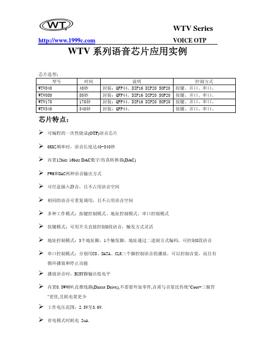
VOICE OTP WTV系列语音芯片应用实例芯片选型:型号时间说明控制方式WTV040 40妙 封装:QFP44、DIP16 DIP20 SOP20按键、并口、串口、 WTV080 80妙 封装:QFP44、DIP16 DIP20 SOP20按键、并口、串口、WTV170 170妙 封装:QFP44、DIP16 DIP20 SOP20按键、并口、串口、WTV340 340妙 封装:QFP44、按键、并口、串口、芯片特点:可编程的一次性烧录(OTP)语音芯片6KHZ频率时,语音长度达40-340秒内置12bits-16bits DAC数字/仿真转换器(DAC)PWM和DAC两种语音输出方式可任意插入静音,且不占用语音空间相同的语音可重复调用,且不占用语音空间多种工作模式:按键控制模式、地址控制模式、串口控制模式按键模式:可用开关直接控制8段语音,触发方式灵活地址控制模式:3个地址脚,1个触发脚,地址通过二进制方式编码,可控制8段语音串口控制模式:分别用CS、DATA、CLK三个脚控制语音的播放,可以控制音量,而且有循环播放和停止功能播放语音时,BUSY脚输出低电平内置0.5W喇叭直推线路(Direct-Drive),不需要外加零件,音质与音量比传统"Cout+三极管"更佳,且耗电量更少工作电压范围:2.5V至3.6V.省电模式时耗电 2uA. VOICE OTP简介:WTV系列语音芯片是一款功能强大的一次性编程语音芯片,6K 取样频率能存储40-340秒的声音,音频输出为PWM或DAC模式。
可选控制方式有按键模式,并口模式,串口模式。
按键模式下触发方式灵活;串口模式下可控制音量,而且有循环播放和停止功能。
语音编程软件操作简单,功能齐全,可以大大缩短芯片的制作周期,且性能可靠,充分利用芯片内部的资源此芯片具有众多单元电路,且有极强的可编程能力,不仅能实现标准的控制方式,亦可根据客户需求,订做各种功能,尽可能的使产品的性价比提升到最高。
广州维创 WTV 系列语音芯片 说明书

2008.5系列语音芯片广州唯创科技有限公司地址:广东省广州市天河区棠东东路25号5楼8563855785638637E-mail:***************网址:◎脉冲不可重复触发◎下一曲不循环触发◎非电平保持可循环触发◎上一曲不循环触发◎电平保持不可循环触发◎下一曲可循环触发◎电平保持可循环触发◎上一曲可循环触发5、应用电路及简析设置芯片的各种控制模式、触发模式都可以使用电脑上位机软件和相关下载器简单完成。
⑴、按键控制模式按键控制模式下的应用电路如下图,由K1、K2、K3和K4四个按键控制触发内部存储语音的播放,一个按键能触发一段语音,也能连续的触发多段语音。
按键可以被设置为任何一种触发方式进行触发,电平触发时为低电平触发,脉冲触发时为负脉冲触发。
LED 可以被设置为放音高电平指示或放音低电平指示。
调节内置功放的外反馈电阻R2、R3能调整输出音量的大小。
由Q1、R8、R9和二极管组成上电复位电路,能有效的解决在电压波动大、外干扰信号强等恶劣环境下所造上的上电死机问题。
⑵、并口控制模式并口控制模式下应用电路如下图。
可以用MCU 对WTV 语音芯片进行控制操作,R10~R16为MCU 跟WTV 语音芯片的通讯电压平衡电阻,电阻的计算公式为(Vin-Vout)×700/Vout =Rn。
由MCU 发送地址直接触发WTV 语音芯片内部语音播放,最多可控制128段语音的播放。
1、芯片简介WTV 系列语音芯片是一款功能强大的一次性编程语音芯片,语音为6K 采样频率时,存储长度可分别达到40秒、80秒、170秒、340秒。
音频输出为PWM 或DAC 模式。
可选控制方式有按键控制模式、按键组合控制模式、并口控制模式、串口控制模式等。
按键控制模式的触发方式灵活;串口模式下可控制音量、打开或关闭功放、有循环播放和停止功能。
可应用在汽车防盗报警器、倒车雷达、GPS 导航仪、智能家居系统、家庭防盗报警器、医疗器械人声提示、娱乐设备(游戏机、游乐机)、学习模型(早教机、儿童有声读物)、智能交通设备(收费站、停车场)通信设备(电话交换机、电话机)、工业控制领域(电梯、工业设备)等领域。
WT588FxxA-8S 语音芯片说明书

深圳唯创知音电子有限公司Shenzhen Waytronic Electronic Co.,LtdWT588FxxA-8S语音芯片说明书版本号:V1.05免责申明:深圳唯创知音电子有限公司申明;说明书以官网资料为准,如若资料内容有更新,不会一一进行通知。
如若使用IC时导致侵犯到第三方专利或其他权利,不承担任何责任。
如若使用我司IC,在航空卫星军事设备,人身安全等领域,造成了重大财产损失或生命伤害,甚至生命死亡,我司不承担任何责任。
目录1.概述 (3)2.功能简述 (3)3.管脚描述 (4)3.1管脚分布图 (4)4.极限参数 (4)5.电气特性 (5)6.一线串口通讯 (5)6.1管脚分配 (5)6.2语音地址对应关系 (6)6.3语音及命令码对应表 (6)6.4一线串口时序图 (7)7.两线串口通讯 (8)7.1管脚分配 (9)7.2语音地址对应关系 (9)7.3语音及命令码对应表 (9)7.4两线串口时序图 (10)8.程序范例 (12)8.1一线串口单字节控制程序 (12)8.2一线串口双字节控制程序 (13)8.3一线串口单字节连码示例(F3+01+F3+02) (14)8.4一线串口双字节连码示例(FFF3+0001+FFF3+0002) (15)8.5二线串口单字节控制程序 (15)8.6二线串口双字节控制程序 (16)8.7二线串口单字节连码示例(F3+01+F3+02) (17)8.8二线串口双字节连码示例(FFF3+0001+FFF3+0002) (18)9.芯片应用原理图 (19)10.客户在线下载器 (20)10.1下载原理图 (21)10.2下载器使用说明 (21)11.炉温曲线参考 (22)12.封装管脚图 (22)说明书以官网和业务员提供为准版本记录版本号修改说明修改日期V1.00原始版本2022-08-30 V1.01增加炉温曲线参考图2022-09-08 V1.02修改笔误2022-11-25 V1.03注意中添加BUSY描述、添加4Mbit版本、修改标题页眉、修改下载2022-12-16器相关描述V1.04增加注意事项,不允许给PC2接上拉电阻2023-03-22 V1.05修改工作电压,修改笔误,增加单字节连码时序图2023-05-131.概述WT588FxxA-8S(WT588F08A-8S(A2)内置8Mbit的FLASH;WT588F04A-8S内置4Mbit的FLASH),WT588F02A-8S内置2Mbit的FLASH),是深圳唯创知音电子有限公司最新研发的一款16位DSP语音芯片、内部振荡32Mhz,16位的PWM解码。
WTR050录音芯片固定语音和录音方案说明书V1.00
/
五、按键控制功能
IO 口 PB0
功能 下一曲可循环(只播放固定语音,不播放录音)
一线串口通讯 一线串口模式可以利用 MCU 通过 DATA 线给 WTN6 系列语音芯片发送数据以达到控制的目
的。可以实现控制语音播放、停止、循环等。
管脚对应关系:
封装形 式
SOP16
PB1 DATA
管脚
PC7 BUSY
一线语音地址对应关系
数据(十六进制) 00H 01H 02H
……. 7EH 7FH 80H
功能 播放第 0 段语音 播放第 1 段语音 播放第 2 段语音
播放第 126 段语音 播放第 127 段语音 播放第 128 段语音
注意:如要播放该地址语音,只要发送该地址就能自动播放该地址语音。
一、产品特点 工作电压 : 2.8V ~ 5.2V ; 不工作时自动进入休眠模式; 具有按键、MCU 控制等功能; 功放直推喇叭, 音量大、高传真、省电 , 0.5 W/8ohm; 具有录音和播放提示功能,可接 LED 显示; 单芯片即可录音,固定语音加录音时长最多 50S;
//延时 1.2ms / /延时 400us
//延时 400us //延时 1.2ms
/
七、应用电路 MIC 录音电路
/
线路录音电路 注:R5 和 R7 为 6.8K,R8 为 4.7K
八、芯片封装 单位:mm
录一段语音存放在录音区域(录音时有滴的一声提示) 播放录音区域的语音内容
删除所有录音文件
FEH
停止当前功能
一线串口时序图
/
播放过程中发送则停止当前语音播放、录音过程中发送则停 止当前录音,如果播放的语音是循环播放的,则停止当前语音 播放并且把循环模式改成不循环。如果当前播放语音为录音文 件,发送这个指令则停止当前播放的语音
wt2605 蓝牙音频芯片资料说明书
WT2605蓝牙音频芯片资料Note:GUANGZHOU ELECTRONIC CO.,LTD.reserves the right to change this document without prior rmation provided by WAYTRONIC is believed to be accurate and reliable.However,WAYTRONIC makes no warranty for any errors which may appearin thisdocument.Contact WAYTRONIC to obtain the latest version of device specifications before placing your orders.No responsibility is assumed by WAYTRONIC for any infringement of patent or other rights of third parties which may result from its use.In addition,WAYTRONIC products are not authorized for use as critical components in life support devices/systems or aviation devices/systems,where a malfunction or failure of the product may reasonably be expected to result in significant injury to the user,without the express written approval ofWAYTRONIC.版本号:V1.09WT2605芯片使用说明目录1.产品概述 (3)1.1描述 (3)1.2MCU和高级特性 (3)1.3专用解决方案 (3)1.4应用(部分举例) (4)2.管脚定义 (6)2.1SSOP24封装管脚描述 (6)3.电器参数 (7)3.1工作条件 (7)3.2IO特性 (7)3.3音频DAC特性 (7)3.4BT参数 (8)3.5音频ADC特性 (8)4.封装信息 (9)4.1SSOP24封装信息 (9)5.版本记录 (10)1.产品概述1.1描述WT2605芯片专为音频蓝牙应用而设计,是广州唯创电子有限公司研发的一款高品质MP3语音编解码蓝牙芯片,内含一个功能强大的DSP(数字信号处理器)核心,通过UART接口与外部器件进行访问以及数据交互,操作简单;芯片内置的模拟接口为用户提供高品质的音频输入和输出,外设接口丰富,可实现不同用户的需求。
语音芯片NV040数据手册V1.2
-第 1 页-
目 录
目 录 ...................................................................................................................................................................................... 2 1 概述 ..................................................................................................................................................................................... 3 2 功能特点 ............................................................................................................................................................................. 3 3 封装示意图 ......................................................................................................................................................................... 3 4 脚位描述 ........................................
一种带有语音提示功能全自动智能炒菜机语音方案
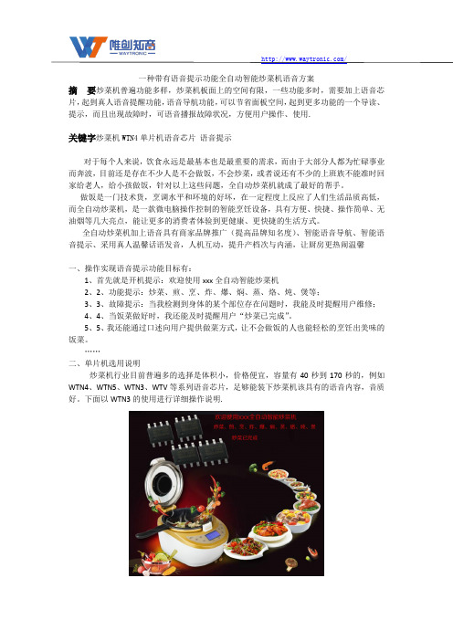
一种带有语音提示功能全自动智能炒菜机语音方案摘要炒菜机普遍功能多样,炒菜机板面上的空间有限,一些功能多时,需要加上语音芯片,起到真人语音提醒功能,语音导航功能,可以节省面板空间,起到更多功能的一个导读、提示,而且出现故障时,可语音播报故障状况,方便用户操作、使用.关键字炒菜机WTN4单片机语音芯片语音提示对于每个人来说,饮食永远是最基本也是最重要的需求,而由于大部分人都为忙碌事业而奔波,目前还是存在不少人是不会做饭,不会炒菜,或者说还有不少的上班族不能准时回家给老人,给小孩做饭,针对以上这些问题,全自动炒菜机就成了最好的帮手。
做饭是一门技术货,烹调水平和环境的好坏,在一定程度上反应了人们生活品质高低,而全自动炒菜机,是一款微电脑操作控制的智能烹饪设备,具有方便、快捷、操作简单、无油烟等几大亮点,能让更多的消费者体验到更健康、更快捷的生活方式。
全自动炒菜机加上语音具有商家品牌推广(提高品牌知名度)、智能语音导航、智能语音提示、采用真人温馨话语发音,人机互动,提升产档次与内涵,让厨房更热闹温馨一、操作实现语音提示功能目标有:1、首先就是开机提示:欢迎使用xxx全自动智能炒菜机2、2、功能提示:炒菜、煎、烹、炸、爆、焖、蒸、烙、炖、煲等;3、3、故障提示:当我检测到身体的某个部位存在问题时,我能及时提醒用户维修;4、4、当饭菜做好时,我还能及时提醒用户“炒菜已完成”。
5、5、我还能通过口述向用户提供做菜方式,让不会做饭的人也能轻松的烹饪出美味的饭菜。
……二、单片机选用说明炒菜机行业目前普遍多的选择是体积小,价格便宜,容量有40秒到170秒的,例如WTN4、WTN5、WTN3、WTV等系列语音芯片,足够能装下炒菜机该具有的语音内容,音质好。
下面以WTN3的使用进行详细操作说明.三、系统语音芯片应用电路说明WTN3系列产品为单芯片CMOS语音合成 IC,现有2个型号分别为WTN3040和WTN3080,时间长度为40秒和80秒(6K采样)。
- 1、下载文档前请自行甄别文档内容的完整性,平台不提供额外的编辑、内容补充、找答案等附加服务。
- 2、"仅部分预览"的文档,不可在线预览部分如存在完整性等问题,可反馈申请退款(可完整预览的文档不适用该条件!)。
- 3、如文档侵犯您的权益,请联系客服反馈,我们会尽快为您处理(人工客服工作时间:9:00-18:30)。
WTN4 系列语音芯片说明书
3 I/O Single-Chip Speech Synthesizer
目录 1、概述............................................................................................................................................. 2 2、功能简述:............................................................................................................................... .. 2 3、管脚描述:............................................................................................................................... .. 2
供电电压范围 2.4V~3.5V 3.6V~5.0V
3.1、WTN4045/WTN4065/WTN4105-8S 管脚介绍
3.1、WTN4045/WTN4065/WTN4105-8S 管脚介绍 ............................................................................... 2 3.2、WTN4165-8S 管脚介绍 ............................................................................................................... 3 3.3、极限参数:............................................................................................................................. 3 3.4、直流特性:............................................................................................................................. 4 4、一线串口通讯:......................................................................................................................... 4 4.1、管脚分配:............................................................................................................................... 5 4.2、一线语音地址对应关系:....................................................................................................... 5 4.3、一线语音及命令码对应表:................................................................................................... 5 4.4、一线串口时序图:................................................................................................................... 5 4.5、一线串口程序范例:............................................................................................................. 6 5、两线串口通讯:......................................................................................................................... 7 5.1、管脚分配:............................................................................................................................. 7 5.2、语音地址对应关系:............................................................................................................. 7 5.3、语音及命令码对应表:......................................................................................................... 8 5.4、两线串口时序图:................................................................................................................. 8 5.5、两线串口程序范例:............................................................................................................. 8 6、数脉冲控制方式:..................................................................................................................... 9 6.1、管脚分配:........................................................................................................................... 10 6.2、语音地址对应关系:........................................................................................................... 10 6.3、数脉冲控制时序:............................................................................................................... 10 6.4、数脉冲程序范例:............................................................................................................... 11 7、应用电路:............................................................................................................................... 11 7.1、WTN4045/065/105-8S 一线串口控制应用电路 .................................................................. 12 7.2 、WTN4045/065/105-8S 两线串口控制应用电路 ................................................................ 12 7.3 、WTN4045/065/105-8S 数脉冲控制应用电路 .................................................................... 12 7.4、WTN4165-8S 一线串口控制应用电路.................................................................................. 13 7.5、WTN4165-8S 两线串口控制应用电路.................................................................................. 13 7.6、WTN4165-8S 数脉冲控制应用电路...................................................................................... 14 8.管脚封装图:........................................................................................................................... 14 9.版本记录............................................................................................................................... .... 15
/
1、概述
WTN4 系列语音芯片是深圳唯创知音电子有限公司推出的一系列语音芯片,其性能优越, 价格实惠。该系列芯片包括 WTN4045、WTN4065、WTN4105(6KHz 采样时语音长度分别为 45s、 65s、105s)等语音芯片。WTN4 为多功能单芯片 CMOS 语音合成 4 位元为控制器。提供一通 道的语音输出,有一组高音质的 PWM 来直推喇叭。语音合成方式采用高音质 ADPCM 演算法, 音频采样率最高可达 44.1KHz 。精准的+/-1%内部震荡,不需要加外部震荡,具备超低功耗 待机。
