实验1-Cisco路由器基本配置+静态路由+广域网连接
Cisco路由器静态路由设计实验报告
一、实训目的(1)掌握Cisco路由器静态路由设计和配置方法。
(2)掌握Cisco路由器默认路由的配置方法。
二、实验环境(1)每组一台路由器、1~3台微机、一根Console电缆、一根交叉双绞线(2)前后组结合,通过一对DTE/DCE电缆将串口相连。
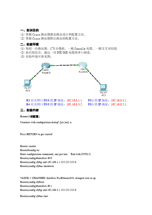
(3)实验环境可参见图:R3以太网口F0/0的IP地址:192.16.8.1.1F0/1的IP地址:192.16.8.3.1 R4以太网口F0/0的IP地址:192.16.8.3.2 F0/1的IP地址:192.16.8.2.1三、实验内容Router3的配置:Continue with configuration dialog? [yes/no]: nPress RETURN to get started!Router>enableRouter#config terEnter configuration commands, one per line. End with CNTL/Z.Router(config)#interface f0/0Router(config-if)#ip add 192.168.1.1 255.255.255.0Router(config-if)#no shutdown%LINK-5-CHANGED: Interface FastEthernet0/0, changed state to upRouter(config-if)#exitRouter(config)#interface f0/1Router(config-if)#ip add 192.168.3.1 255.255.255.0Router(config-if)#no shutRouter4的配置:Continue with configuration dialog? [yes/no]: nPress RETURN to get started!Router>enableRouter#config terEnter configuration commands, one per line. End with CNTL/Z.Router(config)#interface f0/0Router(config-if)#ip add 192.168.3.2 255.255.255.0Router(config-if)#no shut%LINK-5-CHANGED: Interface FastEthernet0/0, changed state to up%LINEPROTO-5-UPDOWN: Line protocol on Interface FastEthernet0/0, changed state to upRouter(config-if)#exitRouter(config)#inter f0/1Router(config-if)#ip add 192.168.2.1 255.255.255.0Router(config-if)#no shut注意事项:(1)严禁带电插、拔串口电缆。
Cisco路由器配置实例(经典)
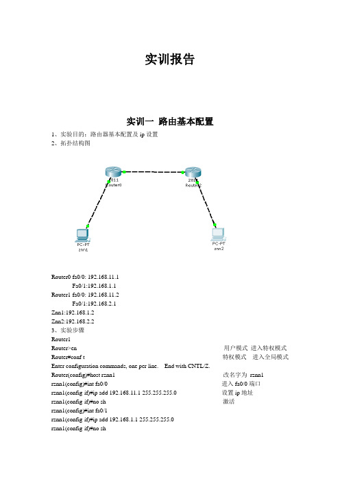
实训报告实训一路由基本配置1、实验目的:路由器基本配置及ip设置2、拓扑结构图Router0 fa0/0: 192.168.11.1Fa0/1:192.168.1.1Router1 fa0/0: 192.168.11.2Fa0/1:192.168.2.1Znn1:192.168.1.2Znn2:192.168.2.23、实验步骤Router1Router>en 用户模式进入特权模式Router#conf t 特权模式进入全局模式Enter configuration commands, one per line. End with CNTL/Z.Router(config)#host rznn1 改名字为rznn1rznn1(config)#int fa0/0 进入fa0/0端口rznn1(config-if)#ip add 192.168.11.1 255.255.255.0 设置ip地址rznn1(config-if)#no sh 激活rznn1(config)#int fa0/1rznn1(config-if)#ip add 192.168.1.1 255.255.255.0rznn1(config-if)#no shrznn1(config-if)#exitrznn1(config)#exitrznn1#copy running-config startup-config 保存Destination filename [startup-config]? startup-configrznn1#conf trznn1(config)#enable secret password 222 设置密文rznn1#show ip interface b 显示Interface IP-Address OK? Method Status Protocol FastEthernet0/0 192.168.11.1 YES manual up up FastEthernet0/1 192.168.1.1 YES manual up upVlan1 unassigned YES manual administratively down downrouter 2outer>enRouter#conf tEnter configuration commands, one per line. End with CNTL/Z.Router(config)#host rznn2rznn2(config)#int fa0/0rznn2(config-if)#ip add 192.168.11.2 255.255.255.0rznn2(config-if)#no shrznn2(config)#int fa0/1rznn2(config-if)#ip add 192.168.2.1 255.255.255.0rznn2(config-if)#no shRznn2#copy running-config startup-config 保存Destination filename [startup-config]? startup-configrznn2(config-if)#exitrznn2(config)#exitrznn2#conf trznn2(config)#enable secret 222rznn2#show ip interface bInterface IP-Address OK? Method Status Protocol FastEthernet0/0 192.168.11.2 YES manual up up FastEthernet0/1 192.168.2.1 YES manual up upVlan1 unassigned YES manual administratively down down实训二1、远程登录、密码设置及验证为路由器开设telnet端口,PC机可以远程登陆到Rznn3(Router 1)拓扑结构图Router0:192.168.1.1Pc:192.168.1.2步骤rznn3>rznn3>enrznn3#conf tEnter configuration commands, one per line. End with CNTL/Z.rznn3(config)#no ip domain lookuprznn3(config)#line cons 0rznn3(config-line)#password znnrznn3(config-line)#loginrznn3(config-line)#no exec-trznn3(config-line)#logg syncrznn3(config-line)#exitrznn3(config)#int fa0/0rznn3(config-if)#ip add 192.168.1.1 255.255.255.0rznn3(config-if)#no shrznn3(config-if)#exitrznn3(config)#line vty 0 4 打通五个端口rznn3(config-line)#password cisco 设置密码rznn3(config-line)#login 保存rznn3(config-line)#exit4、测试:实训三命令组1、目的:八条命令(no ip domain lookup\line cons 0\password\login\no exec-t\logg sync\show version\reload\copy running-config startup-config)\show cdp neighbors)2、拓扑结构图Router0 fa0/0: 192.168.11.1Router1 fa0/0: 192.168.11.23、步骤rznn1#conf tEnter configuration commands, one per line. End with CNTL/Z.1、rznn1(config)#no ip domain lookup 取消域名查找转换2、rznn1(config)#line cons 0 打开cons 0端口3、rznn1(config-line)#password znn 设置密码为znnrznn1(config-line)#login 保存rznn1(config-line)#no exec-t 设置永不超时4、rznn1(config-line)#logg sync 产生日志5、rznn1#show version 显示思科路由系统版本信息Cisco IOS Software, 2800 Software (C2800NM-ADVIPSERVICESK9-M), Version 12.4(15)T1, RELEASE SOFTWARE (fc2)Technical Support: /techsupportCopyright (c) 1986-2007 by Cisco Systems, Inc.Compiled Wed 18-Jul-07 06:21 by pt_rel_team6、rznn1#show cdp neighbors 查看路由器连接的相邻路由器的相关信息Capability Codes: R - Router, T - Trans Bridge, B - Source Route BridgeS - Switch, H - Host, I - IGMP, r - Repeater, P - PhoneDevice ID Local Intrfce Holdtme Capability Platform Port IDrznn2 Fas 0/0 139 R C2800 Fas 0/07、rznn1#copy running-config startup-config 保存刚才指令Destination filename [startup-config]? startup-configBuilding configuration...[OK]8、rznn1#reload 重启路由器Proceed with reload? [confirm]System Bootstrap, Version 12.1(3r)T2, RELEASE SOFTWARE (fc1)Copyright (c) 2000 by cisco Systems, Inc.cisco 2811 (MPC860) processor (revision 0x200) with 60416K/5120K bytes of memorySelf decompressing the image :########################################################################## [OK] Restricted Rights Legendrznn1#show ip interface bInterface IP-Address OK? Method Status Protocol FastEthernet0/0 192.168.11.1 YES manual up up FastEthernet0/1 192.168.1.1 YES manual up upVlan1 unassigned YES manual administratively down down9、rznn1(config-if)#ip add 192.168.3.1 255.255.255.0 重置ip地址rznn1#show ip interface bInterface IP-Address OK? Method Status Protocol FastEthernet0/0 192.168.3.1 YES manual up up FastEthernet0/1 192.168.1.1 YES manual up up Vlan1 unassigned YES manual administratively down down实训四发现协议1、实训目的通过发现协议显示路由器相邻路由的端口信息2、拓扑结构Router0:192.168.11.1Router1:fa0/0 192.168.11.2Fa0/1 192.168.12.1Router2:192.168.12.23、步骤R1路由器Router>enRouter#conf tEnter configuration commands, one per line. End with CNTL/Z.Router(config)#host r1r1(config)#int fa0/0r1(config-if)#ip add 192.168.11.1 255.255.255.0r1(config-if)#no sh%LINK-5-CHANGED: Interface FastEthernet0/0, changed state to upr1(config-if)#r1(config-if)#exitr1(config)#exitr1#%SYS-5-CONFIG_I: Configured from console by consoler1#show ip interface bInterface IP-Address OK? Method Status Protocol FastEthernet0/0 192.168.11.1 YES manual up down FastEthernet0/1 unassigned YES manual administratively down downVlan1 unassigned YES manual administratively down downR2 路由器Router>enRouter#conf tEnter configuration commands, one per line. End with CNTL/Z.Router(config)#host r2r2(config)#int fa0/0r2(config-if)#ip add 192.168.11.2 255.255.255.0r2(config-if)#no sh%LINK-5-CHANGED: Interface FastEthernet0/0, changed state to up%LINEPROTO-5-UPDOWN: Line protocol on Interface FastEthernet0/0, changed state to up r2(config-if)#exitr2(config)#exitr2#%SYS-5-CONFIG_I: Configured from console by consoler2#conf tEnter configuration commands, one per line. End with CNTL/Z.r2(config)#int fa0/0r2(config-if)#int fa0/1r2(config-if)#ip add 192.168.12.1 255.255.255.0r2(config-if)#no sh%LINK-5-CHANGED: Interface FastEthernet0/1, changed state to upr2(config-if)#exitr2(config)#exitr2#%SYS-5-CONFIG_I: Configured from console by consoler2#show ip interface bInterface IP-Address OK? Method Status Protocol FastEthernet0/0 192.168.11.2 YES manual up upFastEthernet0/1 192.168.12.1 YES manual up down Vlan1 unassigned YES manual administratively down downR3路由器Router>enRouter#conf tEnter configuration commands, one per line. End with CNTL/Z.Router(config)#host r3r3(config)#int fa0/0r3(config-if)#ip add 192.168.12.2 255.255.255.0r3(config-if)#no sh%LINK-5-CHANGED: Interface FastEthernet0/0, changed state to up%LINEPROTO-5-UPDOWN: Line protocol on Interface FastEthernet0/0, changed state to up r3(config-if)#exitr3(config)#exitr3#%SYS-5-CONFIG_I: Configured from console by consoler3#show ip interface bInterface IP-Address OK? Method Status Protocol FastEthernet0/0 192.168.12.2 YES manual up up FastEthernet0/1 unassigned YES manual administratively down downVlan1 unassigned YES manual administratively down downR1发现邻居r1#show cdp neighborsCapability Codes: R - Router, T - Trans Bridge, B - Source Route BridgeS - Switch, H - Host, I - IGMP, r - Repeater, P - PhoneDevice ID Local Intrfce Holdtme Capability Platform Port IDr2 Fas 0/0 165 R C2800 Fas 0/0R2发现邻居r2#show cdp neighborsCapability Codes: R - Router, T - Trans Bridge, B - Source Route BridgeS - Switch, H - Host, I - IGMP, r - Repeater, P - PhoneDevice ID Local Intrfce Holdtme Capability Platform Port IDr1 Fas 0/0 176 R C1841 Fas 0/0r3 Fas 0/1 130 R C1841 Fas 0/0R3发现邻居r3#show cdp neighborsCapability Codes: R - Router, T - Trans Bridge, B - Source Route BridgeS - Switch, H - Host, I - IGMP, r - Repeater, P - PhoneDevice ID Local Intrfce Holdtme Capability Platform Port IDr2 Fas 0/0 166 R C2800 Fas 0/14、总结show 命令(1)show ip interface b (显示端口ip信息)(2)show version (显示ios版本信息)(3)show running-config (显示刚才使用的命令配置信息)(4)show cdp neighbors (显示发现邻居直连设备信息)(5)show interface (显示所有端口详细信息)实训五静态路由1、实验目的:将不同网段的网络配通(ip route)Ip route语法:ip route 目标地址子网掩码相邻路由器接口地址Show ip route2、试验拓扑:Router0:192.168.11.1Router1:fa0/0 192.168.11.2Fa0/1 192.168.12.1Router2:192.168.12.23、实验步骤:Router1Router>enRouter#conf tRouter(config)#host r1r1(config)#int fa0/0r1(config-if)#ip add 192.168.11.1 255.255.255.0r1(config-if)#no sh%LINK-5-CHANGED: Interface FastEthernet0/0, changed state to upr1(config-if)#exitr1(config)#exitr1#show ip interface bInterface IP-Address OK? Method Status ProtocolFastEthernet0/0 192.168.11.1 YES manual up downFastEthernet0/1 unassigned YES manual administratively down downVlan1 unassigned YES manual administratively down downr1#%LINEPROTO-5-UPDOWN: Line protocol on Interface FastEthernet0/0, changed state to up r1#ping 192.168.12.1Type escape sequence to abort.Sending 5, 100-byte ICMP Echos to 192.168.12.1, timeout is 2 seconds:.....Success rate is 0 percent (0/5)r1#conf tEnter configuration commands, one per line. End with CNTL/Z.r1(config)#ip route 192.168.12.0 255.255.255.0 192.168.11.2r1(config)#exitr1#ping 192.168.12.1Type escape sequence to abort.Sending 5, 100-byte ICMP Echos to 192.168.12.1, timeout is 2 seconds:Success rate is 100 percent (5/5), round-trip min/avg/max = 31/31/32 msr1#ping 192.168.12.2Type escape sequence to abort.Sending 5, 100-byte ICMP Echos to 192.168.12.2, timeout is 2 seconds:.....Success rate is 0 percent (0/5)r1#ping 192.168.12.2Type escape sequence to abort.Sending 5, 100-byte ICMP Echos to 192.168.12.2, timeout is 2 seconds:Success rate is 100 percent (5/5), round-trip min/avg/max = 47/62/78 msr1#show ip routeCodes: C - connected, S - static, I - IGRP, R - RIP, M - mobile, B - BGPD - EIGRP, EX - EIGRP external, O - OSPF, IA - OSPF inter areaN1 - OSPF NSSA external type 1, N2 - OSPF NSSA external type 2E1 - OSPF external type 1, E2 - OSPF external type 2, E - EGPi - IS-IS, L1 - IS-IS level-1, L2 - IS-IS level-2, ia - IS-IS inter area* - candidate default, U - per-user static route, o - ODRP - periodic downloaded static routeGateway of last resort is not setC 192.168.11.0/24 is directly connected, FastEthernet0/0S 192.168.12.0/24 [1/0] via 192.168.11.2Router3Router>enRouter#conf tEnter configuration commands, one per line. End with CNTL/Z.Router(config)#host r3r3(config)#int fa0/0r3(config-if)#ip add 192.168.12.2 255.255.255.0r3(config-if)#no sh%LINK-5-CHANGED: Interface FastEthernet0/0, changed state to up%LINEPROTO-5-UPDOWN: Line protocol on Interface FastEthernet0/0, changed state to up r3(config-if)#exitr3(config)#exitr3#%SYS-5-CONFIG_I: Configured from console by consoler3#show ip interface bInterface IP-Address OK? Method Status Protocol FastEthernet0/0 192.168.12.2 YES manual up up FastEthernet0/1 unassigned YES manual administratively down downVlan1 unassigned YES manual administratively down downr3#conf tEnter configuration commands, one per line. End with CNTL/Z.r3(config)#ip route 192.168.11.0 255.255.255.0 192.168.12.1r3(config)#exitr3#ping 192.168.11.2Type escape sequence to abort.Sending 5, 100-byte ICMP Echos to 192.168.11.2, timeout is 2 seconds:Success rate is 100 percent (5/5), round-trip min/avg/max = 31/31/32 msr3#ping 192.168.11.1Type escape sequence to abort.Sending 5, 100-byte ICMP Echos to 192.168.11.1, timeout is 2 seconds:Success rate is 100 percent (5/5), round-trip min/avg/max = 62/62/63 msr3#show ip routeCodes: C - connected, S - static, I - IGRP, R - RIP, M - mobile, B - BGPD - EIGRP, EX - EIGRP external, O - OSPF, IA - OSPF inter areaN1 - OSPF NSSA external type 1, N2 - OSPF NSSA external type 2i - IS-IS, L1 - IS-IS level-1, L2 - IS-IS level-2, ia - IS-IS inter area* - candidate default, U - per-user static route, o - ODRP - periodic downloaded static routeGateway of last resort is not setS 192.168.11.0/24 [1/0] via 192.168.12.1C 192.168.12.0/24 is directly connected, FastEthernet0/04、默认路由Route 1r1>enr1#conf tEnter configuration commands, one per line. End with CNTL/Z.r1(config)#no ip route 192.168.12.0 255.255.255.0 192.168.11.2%No matching route to deleter1(config)#exitr1#%SYS-5-CONFIG_I: Configured from console by consoler1#show ip routeCodes: C - connected, S - static, I - IGRP, R - RIP, M - mobile, B - BGPD - EIGRP, EX - EIGRP external, O - OSPF, IA - OSPF inter areaN1 - OSPF NSSA external type 1, N2 - OSPF NSSA external type 2E1 - OSPF external type 1, E2 - OSPF external type 2, E - EGPi - IS-IS, L1 - IS-IS level-1, L2 - IS-IS level-2, ia - IS-IS inter area* - candidate default, U - per-user static route, o - ODRP - periodic downloaded static routeGateway of last resort is not setC 192.168.11.0/24 is directly connected, FastEthernet0/0r1#conf tEnter configuration commands, one per line. End with CNTL/Z.r1(config)#ip route 0.0.0.0 0.0.0.0 192.168.11.2r1(config)#exitr1#%SYS-5-CONFIG_I: Configured from console by consoler1#show ip routeCodes: C - connected, S - static, I - IGRP, R - RIP, M - mobile, B - BGPD - EIGRP, EX - EIGRP external, O - OSPF, IA - OSPF inter areaN1 - OSPF NSSA external type 1, N2 - OSPF NSSA external type 2i - IS-IS, L1 - IS-IS level-1, L2 - IS-IS level-2, ia - IS-IS inter area* - candidate default, U - per-user static route, o - ODRP - periodic downloaded static routeGateway of last resort is 192.168.11.2 to network 0.0.0.0C 192.168.11.0/24 is directly connected, FastEthernet0/0S* 0.0.0.0/0 [1/0] via 192.168.11.2r1#ping 192.168.12.1Type escape sequence to abort.Sending 5, 100-byte ICMP Echos to 192.168.12.1, timeout is 2 seconds:Success rate is 100 percent (5/5), round-trip min/avg/max = 16/28/31 msr1#ping 192.168.12.2Type escape sequence to abort.Sending 5, 100-byte ICMP Echos to 192.168.12.2, timeout is 2 seconds: Success rate is 100 percent (5/5), round-trip min/avg/max = 62/62/63 msRoute 3r1>enr1#conf tEnter configuration commands, one per line. End with CNTL/Z.r1(config)#no ip route 192.168.12.0 255.255.255.0 192.168.11.2%No matching route to deleter1(config)#exitr1#%SYS-5-CONFIG_I: Configured from console by consoler1#show ip routeCodes: C - connected, S - static, I - IGRP, R - RIP, M - mobile, B - BGPD - EIGRP, EX - EIGRP external, O - OSPF, IA - OSPF inter areaN1 - OSPF NSSA external type 1, N2 - OSPF NSSA external type 2E1 - OSPF external type 1, E2 - OSPF external type 2, E - EGPi - IS-IS, L1 - IS-IS level-1, L2 - IS-IS level-2, ia - IS-IS inter area* - candidate default, U - per-user static route, o - ODRP - periodic downloaded static routeGateway of last resort is not setC 192.168.11.0/24 is directly connected, FastEthernet0/0r1#conf tEnter configuration commands, one per line. End with CNTL/Z.r1(config)#ip route 0.0.0.0 0.0.0.0 192.168.11.2r1(config)#exitr1#%SYS-5-CONFIG_I: Configured from console by consoler1#show ip routeCodes: C - connected, S - static, I - IGRP, R - RIP, M - mobile, B - BGPD - EIGRP, EX - EIGRP external, O - OSPF, IA - OSPF inter areaN1 - OSPF NSSA external type 1, N2 - OSPF NSSA external type 2E1 - OSPF external type 1, E2 - OSPF external type 2, E - EGPi - IS-IS, L1 - IS-IS level-1, L2 - IS-IS level-2, ia - IS-IS inter area* - candidate default, U - per-user static route, o - ODRP - periodic downloaded static routeGateway of last resort is 192.168.11.2 to network 0.0.0.0C 192.168.11.0/24 is directly connected, FastEthernet0/0S* 0.0.0.0/0 [1/0] via 192.168.11.2r3#ping 192.168.11.1Type escape sequence to abort.Sending 5, 100-byte ICMP Echos to 192.168.11.1, timeout is 2 seconds: Success rate is 100 percent (5/5), round-trip min/avg/max = 62/62/63 ms实训六动态路由RIP 协议1、实验目的使用配置动态路由启动Rip协议使用到的命令(router rip/network/show ip protocols/show ip route)2、实验拓扑R1 fa0/0 192.168.11.1R2 fa0/0 192.168.11.2fa0/1 192.168.12.1R3 fa0/0 192.168.12.23、实验步骤R1Router>enRouter#conf tEnter configuration commands, one per line. End with CNTL/Z. Router(config)#host r1r1(config)#int fa0/0r1(config-if)#ip add 192.168.11.1 255.255.255.0r1(config-if)#no shr1(config-if)#exitr1(config)#router ripr1(config-router)#network 192.168.11.0r1(config-router)#exitr1(config)#exitr1#%SYS-5-CONFIG_I: Configured from console by consoleR2Router>enRouter#conf tEnter configuration commands, one per line. End with CNTL/Z. Router(config)#host r2r2(config)#int fa0/0r2(config-if)#ip add 192.168.11.2 255.255.255.0r2(config-if)#no shr2(config-if)#exitr2(config)#int fa0/1r2(config-if)#ip add 192.168.12.1 255.255.255.0r2(config-if)#no shr2(config-if)#exitr2(config)#router ripr2(config-router)#network 192.168.11.0r2(config-router)#network 192.168.12.0r2(config-router)#exitr2(config)#exitr2#R3Router>enRouter#conf tEnter configuration commands, one per line. End with CNTL/Z. Router(config)#host r3r3(config)#int fa0/0r3(config-if)#ip add 192.168.12.2 255.255.255.0r3(config-if)#no shr3(config-if)#exitr3(config)#router ripr3(config-router)#network 192.168.12.0r3(config-router)#exitr3(config)#exitr3#%SYS-5-CONFIG_I: Configured from console by console4、实验测试R1r1#show ip protocolsRouting Protocol is "rip"Sending updates every 30 seconds, next due in 10 secondsInvalid after 180 seconds, hold down 180, flushed after 240 Outgoing update filter list for all interfaces is not setIncoming update filter list for all interfaces is not set Redistributing: ripDefault version control: send version 1, receive any version Interface Send Recv Triggered RIP Key-chain FastEthernet0/0 1 2 1Automatic network summarization is in effectMaximum path: 4Routing for Networks:192.168.11.0Passive Interface(s):Routing Information Sources:Gateway Distance Last UpdateDistance: (default is 120)r1#show ip routeCodes: C - connected, S - static, I - IGRP, R - RIP, M - mobile, B - BGPD - EIGRP, EX - EIGRP external, O - OSPF, IA - OSPF inter areaN1 - OSPF NSSA external type 1, N2 - OSPF NSSA external type 2E1 - OSPF external type 1, E2 - OSPF external type 2, E - EGPi - IS-IS, L1 - IS-IS level-1, L2 - IS-IS level-2, ia - IS-IS inter area* - candidate default, U - per-user static route, o - ODRP - periodic downloaded static routeGateway of last resort is not setC 192.168.11.0/24 is directly connected, FastEthernet0/0R 192.168.12.0/24 [120/1] via 192.168.11.2, 00:00:24, FastEthernet0/0 r1#ping 192.168.12.0Type escape sequence to abort.Sending 5, 100-byte ICMP Echos to 192.168.12.0, timeout is 2 seconds: Success rate is 100 percent (5/5), round-trip min/avg/max = 31/31/32 msR2r2#show ip protocolsRouting Protocol is "rip"Sending updates every 30 seconds, next due in 21 secondsInvalid after 180 seconds, hold down 180, flushed after 240Outgoing update filter list for all interfaces is not setIncoming update filter list for all interfaces is not setRedistributing: ripDefault version control: send version 1, receive any versionInterface Send Recv Triggered RIP Key-chain FastEthernet0/0 1 2 1FastEthernet0/1 1 2 1Automatic network summarization is in effectMaximum path: 4Routing for Networks:192.168.11.0192.168.12.0Passive Interface(s):Routing Information Sources:Gateway Distance Last UpdateDistance: (default is 120)r2#show ip routeCodes: C - connected, S - static, I - IGRP, R - RIP, M - mobile, B - BGPD - EIGRP, EX - EIGRP external, O - OSPF, IA - OSPF inter areaN1 - OSPF NSSA external type 1, N2 - OSPF NSSA external type 2E1 - OSPF external type 1, E2 - OSPF external type 2, E - EGPi - IS-IS, L1 - IS-IS level-1, L2 - IS-IS level-2, ia - IS-IS inter area* - candidate default, U - per-user static route, o - ODRP - periodic downloaded static routeGateway of last resort is not setC 192.168.11.0/24 is directly connected, FastEthernet0/0C 192.168.12.0/24 is directly connected, FastEthernet0/1R3r3#show ip protocolsRouting Protocol is "rip"Sending updates every 30 seconds, next due in 15 secondsInvalid after 180 seconds, hold down 180, flushed after 240Outgoing update filter list for all interfaces is not setIncoming update filter list for all interfaces is not setRedistributing: ripDefault version control: send version 1, receive any versionInterface Send Recv Triggered RIP Key-chain FastEthernet0/0 1 2 1Automatic network summarization is in effectMaximum path: 4Routing for Networks:192.168.12.0Passive Interface(s):Routing Information Sources:Gateway Distance Last UpdateDistance: (default is 120)r3#show ip routeCodes: C - connected, S - static, I - IGRP, R - RIP, M - mobile, B - BGPD - EIGRP, EX - EIGRP external, O - OSPF, IA - OSPF inter areaN1 - OSPF NSSA external type 1, N2 - OSPF NSSA external type 2E1 - OSPF external type 1, E2 - OSPF external type 2, E - EGPi - IS-IS, L1 - IS-IS level-1, L2 - IS-IS level-2, ia - IS-IS inter area* - candidate default, U - per-user static route, o - ODRP - periodic downloaded static routeGateway of last resort is not setR 192.168.11.0/24 [120/1] via 192.168.12.1, 00:00:04, FastEthernet0/0 C 192.168.12.0/24 is directly connected, FastEthernet0/0r3#ping 192.168.11.0Type escape sequence to abort.Sending 5, 100-byte ICMP Echos to 192.168.11.0, timeout is 2 seconds: Success rate is 100 percent (5/5), round-trip min/avg/max = 31/31/32 ms实训七负载平衡试训目的实现负载平衡实训拓扑R1 fa0/0 192.168.11.1R2 eth0/0/0 192.168.11.2Fa0/0 192.168.12.1Fa0/0 192.168.13.1R3 fa0/0 192.168.12.2Fa0/1 192.168.14.1R4 fa0/0 192.168.13.2Fa0/1 192.168.15.1R5 fa0/0 192.168.14.2Fa0/1 192.168.15.2实训步骤(R1 )r1>enR1#conf tR1(config)#ip route 0.0.0.0 0.0.0.0 192.168.11.2R1(config)#exitr1#show ip routeCodes: C - connected, S - static, I - IGRP, R - RIP, M - mobile, B - BGPD - EIGRP, EX - EIGRP external, O - OSPF, IA - OSPF inter areaN1 - OSPF NSSA external type 1, N2 - OSPF NSSA external type 2E1 - OSPF external type 1, E2 - OSPF external type 2, E - EGPi - IS-IS, L1 - IS-IS level-1, L2 - IS-IS level-2, ia - IS-IS inter area* - candidate default, U - per-user static route, o - ODRP - periodic downloaded static routeGateway of last resort is 192.168.11.2 to network 0.0.0.0C 192.168.11.0/24 is directly connected, FastEthernet0/0S* 0.0.0.0/0 [1/0] via 192.168.11.2(R2)r2>enr2(config)#ip route 0.0.0.0 0.0.0.0 192.168.12.2r2(config)#ip route 0.0.0.0 0.0.0.0 192.168.13.2r2(config)#exitr2#%SYS-5-CONFIG_I: Configured from console by consoles% Ambiguous command: "s"r2#show ip routeCodes: C - connected, S - static, I - IGRP, R - RIP, M - mobile, B - BGPD - EIGRP, EX - EIGRP external, O - OSPF, IA - OSPF inter areaN1 - OSPF NSSA external type 1, N2 - OSPF NSSA external type 2E1 - OSPF external type 1, E2 - OSPF external type 2, E - EGPi - IS-IS, L1 - IS-IS level-1, L2 - IS-IS level-2, ia - IS-IS inter area* - candidate default, U - per-user static route, o - ODRP - periodic downloaded static routeGateway of last resort is 192.168.12.2 to network 0.0.0.0C 192.168.11.0/24 is directly connected, Ethernet0/0/0C 192.168.12.0/24 is directly connected, FastEthernet0/0C 192.168.13.0/24 is directly connected, FastEthernet0/1S* 0.0.0.0/0 [1/0] via 192.168.12.2[1/0] via 192.168.13.2(R3)r3>enr3#conf tEnter configuration commands, one per line. End with CNTL/Z.r3(config)#ip route 0.0.0.0 0.0.0.0 192.168.12.1r3(config)#exitr3#%SYS-5-CONFIG_I: Configured from console by consoler3#show ip routeCodes: C - connected, S - static, I - IGRP, R - RIP, M - mobile, B - BGPD - EIGRP, EX - EIGRP external, O - OSPF, IA - OSPF inter areaN1 - OSPF NSSA external type 1, N2 - OSPF NSSA external type 2E1 - OSPF external type 1, E2 - OSPF external type 2, E - EGPi - IS-IS, L1 - IS-IS level-1, L2 - IS-IS level-2, ia - IS-IS inter area* - candidate default, U - per-user static route, o - ODRP - periodic downloaded static routeGateway of last resort is 192.168.12.1 to network 0.0.0.0C 192.168.12.0/24 is directly connected, FastEthernet0/0C 192.168.14.0/24 is directly connected, FastEthernet0/1S* 0.0.0.0/0 [1/0] via 192.168.12.1(R4)r4>enr4#conf tEnter configuration commands, one per line. End with CNTL/Z.r4(config)#ip route 0.0.0.0 0.0.0.0 192.168.13.1r4(config)#exitr4#%SYS-5-CONFIG_I: Configured from console by consoler4#show ip routeCodes: C - connected, S - static, I - IGRP, R - RIP, M - mobile, B - BGPD - EIGRP, EX - EIGRP external, O - OSPF, IA - OSPF inter areaN1 - OSPF NSSA external type 1, N2 - OSPF NSSA external type 2E1 - OSPF external type 1, E2 - OSPF external type 2, E - EGPi - IS-IS, L1 - IS-IS level-1, L2 - IS-IS level-2, ia - IS-IS inter area* - candidate default, U - per-user static route, o - ODRP - periodic downloaded static routeGateway of last resort is 192.168.13.1 to network 0.0.0.0C 192.168.13.0/24 is directly connected, FastEthernet0/0C 192.168.15.0/24 is directly connected, FastEthernet0/1S* 0.0.0.0/0 [1/0] via 192.168.13.1(R5)r5>enr5#conf tEnter configuration commands, one per line. End with CNTL/Z.r5(config)#ip route 0.0.0.0 0.0.0.0 192.168.14.1r5(config)#ip route 0.0.0.0 0.0.0.0 192.168.15.1r5(config)#exitr5#%SYS-5-CONFIG_I: Configured from console by consoler5#show ip routeCodes: C - connected, S - static, I - IGRP, R - RIP, M - mobile, B - BGPD - EIGRP, EX - EIGRP external, O - OSPF, IA - OSPF inter areaN1 - OSPF NSSA external type 1, N2 - OSPF NSSA external type 2E1 - OSPF external type 1, E2 - OSPF external type 2, E - EGPi - IS-IS, L1 - IS-IS level-1, L2 - IS-IS level-2, ia - IS-IS inter area* - candidate default, U - per-user static route, o - ODRP - periodic downloaded static routeGateway of last resort is 192.168.14.1 to network 0.0.0.0C 192.168.14.0/24 is directly connected, FastEthernet0/0C 192.168.15.0/24 is directly connected, FastEthernet0/1S* 0.0.0.0/0 [1/0] via 192.168.14.1[1/0] via 192.168.15.1实训测试(R1)r1#ping 192.168.14.1Type escape sequence to abort.Sending 5, 100-byte ICMP Echos to 192.168.14.1, timeout is 2 seconds:Success rate is 100 percent (5/5), round-trip min/avg/max = 62/84/94 ms (R5)r5#ping 192.168.11.1Type escape sequence to abort.Sending 5, 100-byte ICMP Echos to 192.168.11.1, timeout is 2 seconds: Success rate is 100 percent (5/5), round-trip min/avg/max = 79/91/94 ms实训八DHCP 协议配置实训目的全网配通实训拓扑Fa0/0 192.168.11.1Fa0/1 192.168.12.1实训步骤Router>enRouter#conf tEnter configuration commands, one per line. End with CNTL/Z.Router(config)#host r1r1(config)#int fa0/0r1(config-if)#ip add 192.168.11.1 255.255.255.0r1(config-if)#no shr1(config-if)#exitr1(config)#int fa0/1r1(config-if)#ip add 192.168.12.1 255.255.255.0r1(config-if)#no shr1(config-if)#exitr1(config)#ip dhcp pool znn //配置一个根地址池znnr1(dhcp-config)#network 192.168.11.0 255.255.255.0 //为所有客户机动态分配的地址段r1(dhcp-config)#default-router 192.168.11.1 //为客户机配置默认的网关r1(dhcp-config)#dns-server 192.168.11.1 //为客户机配置DNS服务器r1(dhcp-config)#exitr1(config)#ip dhcp pool znn1r1(dhcp-config)#network 192.168.12.0 255.255.255.0r1(dhcp-config)#default-router 192.168.12.1r1(dhcp-config)#dns-server 192.168.12.1r1(dhcp-config)#exit。
《计算机网络技术》实验指导书:Cisco路由器的基本配置

《计算机网络技术》实验指导书:Cisco路由器的基本配置【实验目的】:1.熟练使用超级终端对路由器进行配置2.学习路由器命令3.掌握路由器的基本连接和配置【实验内容】:1.超级终端的使用2.路由器的启动和初始配置3.路由器的常规配置【实验原理及相关知识】:路由器可以用来连通不同的网络,并且能够选择信息传送的路径。
选择通畅快捷的路径,能大大提高信息速度,减轻网络系统通信负荷,节约网络系统资源,提高网络系统畅通率,从而让网络系统发挥出更大的效益。
从过滤网络流量的角度来看,路由器的作用与交换机、网桥非常相似。
但是与工作在网络底层、从物理上划分网段的交换机不同,路由器使用专门的软件协议从逻辑上对整个网络进行划分。
例如,一台支持IP协议的路由器可以把网络划分成多个子网络,只有网间的网络流量才可以通过路由器。
对于每一个接收到的数据包,路由器都会重新计算其校验值,并写入新的物理地址。
因此使用路由器转发和过滤数据的速度往往要比只查看数据包物理地址的交换机慢,但是对于那些结构复杂的网络,使用路由器可以提高网络的整体效率。
路由器的另一个明显优势就是可以自动过滤网络广播。
总体来说,在网络中添加路由器的整个安装过程要比安装即插即用的交换机复杂的多。
一般来说,异种网络互联或多个子网互联都应采用路由器来完成。
路由器的主要工作就是为经过路由的每个数据包寻找一条最佳的传输路径,并将该数据有效地址传送到目的站点。
由此可见,选择最佳路径的策略是路由器的关键所在。
为了完成这项工作,在路由表中保存着子网的标志信息、网上路由的个数和下一个路由器的名字等内容。
路由表可以由系统管理员固定设置,也可以由系统动态修改;可以由路由器自动调整,也可以由主机控制。
路由器的构成从硬件组成上来看,路由器由CPU、内存和接口等部分组成。
1 CPU路由器和PC机一样,有中央处理单元CPU,CPU是路由器的处理中心。
对于不同的路由器,其CPU一般也不一样。
2 内存内存用来存储路由器的信息和数据,Cisco路由器有以下几种内存组件:(1)ROM(Read Only Memory)ROM中存储路由器加电自检程序(Power-On Self-Test Program)启动程序(Bootstrap Program)和部分或全部的IOS。
Cisco(思科)路由器静态路由的配置

Cisco(思科)路由器静态路由的配置实验拓扑实验步骤我们要使得 1.1.1.0/24、2.2.2.0/24、3.3.3.0/24 ⽹络之间能够互相通信。
(1)步骤 1:在各路由器上配置 IP 地址、保证直连链路的连通性R1(config)#int loopback0R1(config-if)#ip address 1.1.1.1 255.255.255.0R1(config)#int s0/0/0R1(config-if)#ip address 192.168.12.1 255.255.255.0R1(config-if)#no shutdownR2(config)#int loopback0R2(config-if)#ip address 2.2.2.2 255.255.255.0R2(config)#int s0/0/0R2(config-if)#clock rate 128000R2(config-if)#ip address 192.168.12.2 255.255.255.0R2(config-if)#no shutdownR2(config)#int s0/0/1R2(config-if)#clock rate 128000R2(config-if)#ip address 192.168.23.2 255.255.255.0R2(config-if)#no shutdownR3(config)#int loopback0R3(config-if)#ip address 3.3.3.3 255.255.255.0R3(config)#int s0/0/1R3(config-if)#ip address 192.168.23.3 255.255.255.0R3(config-if)#no shutdown(2)步骤 2:R1上配置静态路由R1(config)#ip route 2.2.2.0 255.255.255.0 s0/0/0//下⼀跳为接⼝形式,s0/0/0 是点对点的链路,注意应该是 R1 上的s0/0/0 接⼝R1(config)#ip route 3.3.3.0 255.255.255.0 192.168.12.2//下⼀跳为IP 地址形式,192.168.12.2 是R2 上的IP 地址(3)步骤 3:R2上配置静态路由R2(config)#ip route 1.1.1.0 255.255.255.0 s0/0/0R2(config)#ip route 3.3.3.0 255.255.255.0 s0/0/1(4)步骤 4:R3上配置静态路由R3(config)#ip route 1.1.1.0 255.255.255.0 s0/0/1R3(config)#ip route 2.2.2.0 255.255.255.0 s0/0/1实验调试(1)在 R1、R2、R3 上查看路由表R1#show ip routeCodes: C - connected, S - static, R - RIP, M - mobile, B - BGPD - EIGRP, EX - EIGRP external, O - OSPF, IA - OSPF inter areaN1 - OSPF NSSA external type 1, N2 - OSPF NSSA external type 2E1 - OSPF external type 1, E2 - OSPF external type 2 i - IS-IS, su - IS-IS summary, L1 - IS-IS level-1, L2 - IS-IS level-2 ia - IS-IS inter area, * - candidate default, U - per-user static routeo - ODR, P - periodic downloaded static routeGateway of last resort is not setC 192.168.12.0/24 is directly connected, Serial0/0/01.0.0.0/24 is subnetted, 1 subnetsC 1.1.1.0 is directly connected, Loopback02.0.0.0/24 is subnetted, 1 subnetsS 2.2.2.0 is directly connected, Serial0/0/03.0.0.0/24 is subnetted, 1 subnetsS 3.3.3.0 [1/0] via 192.168.12.2R2#show ip routeCodes: C - connected, S - static, R - RIP, M - mobile, B - BGPD - EIGRP, EX - EIGRP external, O - OSPF, IA - OSPF inter areaN1 - OSPF NSSA external type 1, N2 - OSPF NSSA external type 2E1 - OSPF external type 1, E2 - OSPF external type 2i - IS-IS, su - IS-IS summary, L1 - IS-IS level-1, L2 - IS-IS level-2ia - IS-IS inter area, * - candidate default, U - per-user static routeo - ODR, P - periodic downloaded static routeGateway of last resort is not setC 192.168.12.0/24 is directly connected, Serial0/0/01.0.0.0/24 is subnetted, 1 subnetsS 1.1.1.0 is directly connected, Serial0/0/02.0.0.0/24 is subnetted, 1 subnetsC 2.2.2.0 is directly connected, Loopback03.0.0.0/24 is subnetted, 1 subnetsS 3.3.3.0 is directly connected, Serial0/0/1C 192.168.23.0/24 is directly connected, Serial0/0/1R3#show ip routeCodes: C - connected, S - static, R - RIP, M - mobile, B - BGPD - EIGRP, EX - EIGRP external, O - OSPF, IA - OSPF inter areaN1 - OSPF NSSA external type 1, N2 - OSPF NSSA external type 2E1 - OSPF external type 1, E2 - OSPF external type 2i - IS-IS, su - IS-IS summary, L1 - IS-IS level-1, L2 - IS-IS level-2ia - IS-IS inter area, * - candidate default, U - per-user static routeo - ODR, P - periodic downloaded static routeGateway of last resort is not set1.0.0.0/24 is subnetted, 1 subnetsS 1.1.1.0 is directly connected, Serial0/0/12.0.0.0/24 is subnetted, 1 subnetsS 2.2.2.0 is directly connected, Serial0/0/13.0.0.0/24 is subnetted, 1 subnets C 3.3.3.0 is directly connected, Loopback0C 192.168.23.0/24 is directly connected, Serial0/0/1(2)从各路由器的环回⼝ ping 其他路由器的环回⼝:R1#ping//不带任何参数的 ping命令,允许我们输⼊更多的参数Protocol [ip]:Target IP address: 2.2.2.2 //⽬标IP地址Repeat count [5]: //发送的ping 次数Datagram size [100]: //ping包的⼤⼩Timeout in seconds [2]: //超时时间Extended commands [n]: y //是否进⼀步扩展命令Source address or interface: 1.1.1.1 //源IP地址Type of service [0]:Set DF bit in IP header? [no]:Validate reply data? [no]:Data pattern [0xABCD]:Loose, Strict, Record, Timestamp, Verbose[none]:Sweep range of sizes [n]:Type escape sequence to abort.Sending 5, 100-byte ICMP Echos to 2.2.2.2, timeout is 2 seconds:Packet sent with a source address of 1.1.1.1Success rate is 100 percent (5/5), round-trip min/avg/max = 12/14/16 ms//以上说明从 R1 的 loopback0 可以ping 通R2 上的 loopback0。
思科,静态路由实验详细配置教程
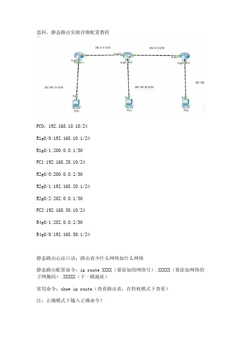
思科,静态路由实验详细配置教程PC0:192.168.10.10/24R1g0/0:192.168.10.1/24R1g0/1:200.0.0.1/30PC1:192.168.20.10/24R2g0/0:200.0.0.2/30R2g0/1:192.168.20.1/24R2g0/2:202.0.0.1/30PC2:192.168.30.10/24R4g0/1:202.0.0.2/30R4g0/0:192.168.30.1/24静态路由心法口诀:路由表少什么网络加什么网络静态路由配置命令:ip route XXXX(要添加的网络号).XXXXX(要添加网络的子网掩码).XXXXX(下一跳地址)常用命令:show ip route(查看路由表,在特权模式下查看)注:正确模式下输入正确命令!配置:R1命令:R1>en //进入特权模式R1#conf t //进入全局配置模式R1(config)#inter g0/0 //进入g0/0接口R1(config-if)#ip add 192.168.10.1 255.255.255.0 //给g0/0接口配置IP地址R1(config-if)#no shutdown //激活g0/0接口R1(config-if)#inter g0/1R1(config-if)#ip add 200.0.0.1 255.255.255.252R1(config-if)#no shutdownR1(config-if)#exit(根据心法口诀可以先在特权模式下先执行show ip route(查看路由表)看看少哪些网段少什么网段加什么网段)R1(config)#ip route 192.168.20.0(要添加网络的网络号) 255.255.255.0 200.0.0.2 (下一跳地址这里是R2路由的g0/0接口) //(配置静态路由,把192.168.20.0网络添加的R1的路由表,可以在特权模式下执行show ip route查看)R1(config)#ip route 202.0.0.0 255.255.255.252 200.0.0.2 //(将202.0.0.0段添加到路由表)R1(config)#ip route 192.168.30.0 255.255.255.0 200.0.0.2 //(将192.168.30.0段添加到路由表)R2命令:R2>enR2#conf tR2(config)#inter g0/0R2(config-if)#ip add 200.0.0.2 255.255.255.252R2(config-if)#no shutdownR2(config-if)#inter g0/1R2(config-if)#ip add 192.168.20.1 255.255.255.0R2(config-if)#no shutdownR2(config-if)#inter g0/2R2(config-if)#ip add 202.0.0.1 255.255.255.252R2(config-if)#no shutdownR2(config-if)#exitR2(config)#ip route 192.168.10.0 255.255.255.0 200.0.0.1 R2(config)#ip route 192.168.30.0 255.255.255.0 202.0.0.2R4命令:R4>enR4#conf tR4(config)#inter g0/1R4(config-if)#ip add 202.0.0.2 255.255.255.252R4(config-if)#no shutdownR4(config-if)#inter g0/0R4(config-if)#ip add 192.168.30.1 255.255.255.0R4(config-if)#no shutdownR4(config-if)#exitR4(config)#ip route 192.168.10.0 255.255.255.0 202.0.0.1 R4(config)#ip route 200.0.0.0 255.255.255.252 202.0.0.1 R4(config)#ip route 192.168.20.0 255.255.255.0 202.0.0.1用pc ping测试,全网互通有兴趣朋友可以了解更多java教程/java/video.shtml。
实验1. 配置静态路由

实验1. 静态路由基础配置1 应用背景管理员可以通过手工的方法在路由器中直接配置路由表,这就是静态路由。
虽然静态路由不适合于在大的网络中使用,但是由于静态路由简单、路由器负载小、安全性高等原因,现在在ISP、金融、证券等单位经常被使用。
2 实验目的通过本实验,掌握以下技能:◆路由表的概念◆命令ip route的使用,以及静态路由跟下一条地址和接口◆根据需求正确的配置静态路由◆掌握验证静态路由的命令3 设备需求:思科路由器 3640 三台4 实验拓扑:Hlsz_R1Hlsz_R3Hlsz_R2LOOPBACK 0Ip add 1.1.1.1/32LOOPBACK 0Ip add 3.3.3.3/32成都互联神州网络技术培训S2/0S2/0S2/1S2/15 实验步骤5.1、静态路由配置静态路由让R1 loopback 0:1.1.1.1/24、R2 loopback 0:2.2.2.2/24、R3 loopback 0:3.3.3.3/24能够相互通信5.1.1、基本配置配置接口IP地址,保证直连链路的互通R1(config)#int loopback0R1(config-if)#ip address 1.1.1.1 255.255.255.0R1(config)#int s2/0R1(config-if)#ip address 12.1.1.1 255.255.255.0R1(config-if)#no shutdownR2(config)#int loopback0R2(config-if)#ip address 2.2.2.2 255.255.255.0R2(config)#int s2/0R2(config-if)#clock rate 64000 /DCE端配置时钟速率R2(config-if)#ip address 12.1.1.2 255.255.255.0R2(config-if)#no shutdownR2(config)#int s2/1R2(config-if)#clock rate 64000 /DCE端配置时钟速率R2(config-if)#ip address 23.1.1.2 255.255.255.0R2(config-if)#no shutdownR3(config)#int loopback0R3(config-if)#ip address 3.3.3.3 255.255.255.0R3(config)#int s2/1R3(config-if)#ip address 23.1.1.3 255.255.255.0R3(config-if)#no shutdown5.1.2、配置静态路由静态路由指向下一跳地址R1(config)#ip route 3.3.3.0 255.255.255.0 12.1.1.2R1(config)#ip route 2.2.2.0 255.255.255.0 12.1.1.2R1(config)#ip route 23.1.1.0 255.255.255.0 12.1.1.2/在R1上配置静态路由分别到网段:23.1.1.0、3.3.3.0和2.2.2.0,采用下一跳IP地址的形式,注意IP:12.1.1.2是R2上S2/0接口IP地址。
实验1-Cisco路由器基本配置+静态路由+广域网连接

静态路由
• 由网络管理员在路由器上手工添加路由信息以实 现路由目的。 • 作用
– 在不会显著增长的小型网络中,使用静态路由便于维 护路由表。 – 静态路由可以路由到存根网络,或者从存根网络路由 到外部网络。
– 使用单一默认路由。如果某个网络在路由表中找不到 更匹配的路由条目,则可使用静态路由作为通往该网 络的路径。
– 在 Windows 中的【开始】→【程序】→【附件】→【通信】菜单 下打开“超级终端”程序,在“名称”对话框中输入名称,例如 “Router”;按【确定】按钮。在“连接时使用”下拉菜单中选择 计算机的 COM1口,按【确定】按钮。
9
通过Console口访问路由器
• 步骤 3:设置通信参数;
• 步骤 4:路由器开机 ,观察路由器的开机过程。
这是一条单方向的路径,必须配置一条相反的路径。
静态路由举例
R1的配置命令: Router> Router>enable Router#configure terminal Router(config)#hostname R1 R1(config)#interface fa0/0 R1(config-if)#ip address 10.1.1.1 255.255.255.0 R1(config-if)#no shutdown R1(config-if)#interface fa0/1 R1(config-if)#ip address 202.128.1.1 255.255.255.0 R1(config-if)#no shutdown R1(config-if)#exit R1(config)#ip route 200.168.10.0 255.255.255.0 10.1.1.2
– 在特权模式下输入相应的命令时进入 – 例如:interface fastEthernet0/0 router(config-if)#
Cisco路由器静态路由和默认路由的配置
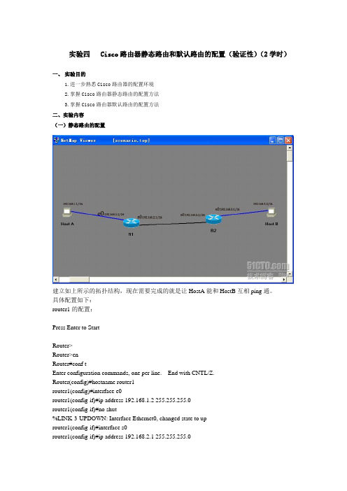
实验四 Cisco路由器静态路由和默认路由的配置(验证性)(2学时)一、实验目的1.进一步熟悉Cisco路由器的配置环境2.掌握Cisco路由器静态路由的配置方法3.掌握Cisco路由器默认路由的配置方法二、实验内容(一)静态路由的配置建立如上所示的拓扑结构,现在需要完成的就是让HostA能和HostB互相ping通。
具体配置如下:router1的配置:Press Enter to StartRouter>Router>enRouter#conf tEnter configuration commands, one per line. End with CNTL/Z.Router(config)#hostname router1router1(config)#interface e0router1(config-if)#ip address 192.168.1.2 255.255.255.0router1(config-if)#no shut%LINK-3-UPDOWN: Interface Ethernet0, changed state to uprouter1(config-if)#interface s0router1(config-if)#ip address 192.168.2.1 255.255.255.0router1(config-if)#clock rate 6400 //clock rate是dce设备给dte设备提供时钟频率的,需要在dce里面设置,而另外的一个路由器里面则不用设置router1(config-if)#no shut%LINK-3-UPDOWN: Interface Serial0, changed state to uprouter1(config-if)#end%LINK-3-UPDOWN: Interface Serial0, changed state to down%LINEPROTO-5-UPDOWN: Line protocol on Interface Serial0, changed state to downrouter1#config tEnter configuration commands, one per line. End with CNTL/Z.router1(config)#ip route 192.168.3.0 255.255.255.0 192.168.2.1 //设定静态路由router1(config)#ip route 192.168.2.0 255.255.255.0 192.168.2.1router1(config)#endrouter1#copy running startupDestination filename [startup-config]?Building configuration...[OK]%LINK-3-UPDOWN: Interface Serial0, changed state to up%LINEPROTO-5-UPDOWN: Line protocol on Interface Serial0, changed state to uprouter2的配置:Press Enter to StartRouter>enRouter#conf tEnter configuration commands, one per line. End with CNTL/Z.Router(config)#interface e0Router(config-if)#endRouter#config tEnter configuration commands, one per line. End with CNTL/Z.Router(config)#hostname router2router2(config)#interface s0router2(config-if)#ip address 192.168.2.2 255.255.255.0router2(config-if)#no shut%LINK-3-UPDOWN: Interface Serial0, changed state to uprouter2(config-if)#interface s0router2(config-if)#interface e0router2(config-if)#ip address 192.168.3.1 255.255.255.0router2(config-if)#no shut%LINK-3-UPDOWN: Interface Ethernet0, changed state to uprouter2(config-if)#endrouter2#config tEnter configuration commands, one per line. End with CNTL/Z.router2(config)#ip route 192.168.1.0 255.255.255.0 192.168.2.2router2(config)#ip route 192.168.2.0 255.255.255.0 192.168.2.2router2(config)#endrouter2#copy running startupDestination filename [startup-config]?Building configuration...[OK]router2#ping 192.168.1.2Type escape sequence to abort.Sending 5, 100-byte ICMP Echos to 192.168.1.2, timeout is 2 seconds:!!!!!Success rate is 100 percent (5/5), round-trip min/avg/max = 1/2/4 msrouter2#ping 192.168.2.1Type escape sequence to abort.Sending 5, 100-byte ICMP Echos to 192.168.2.1, timeout is 2 seconds:!!!!!Success rate is 100 percent (5/5), round-trip min/avg/max = 1/2/4 msrouter2#ping 192.168.2.2Type escape sequence to abort.Sending 5, 100-byte ICMP Echos to 192.168.2.2, timeout is 2 seconds:!!!!!Success rate is 100 percent (5/5), round-trip min/avg/max = 1/2/4 ms //路由器之间试ping 一下,应该可以ping通,接下来配pcpc1的配置如下:Boson BOSS 5.0Copyright 1998-2003 Boson Software, Inc.Use the command help to get startedPress Enter to beginC:>ipconfig /ip 192.168.1.1 255.255.255.0 //此时尚未指定网关C:>ping 192.168.2.1Pinging 192.168.2.1 with 32 bytes of data:Request timed out.Request timed out.Request timed out.Request timed out.Request timed out.Ping statistics for 192.168.2.1:Packets: Sent = 5, Received = 0, Lost = 5 (100% loss), //未指定网关时不能ping通router1的s0Approximate round trip times in milli-seconds:Minimum = 0ms, Maximum = 0ms, Average = 0msC:>ipconfig /dg 192.168.1.2 //指定网关为与本机直连的router1的e0口C:>ping 192.168.1.2Pinging 192.168.1.2 with 32 bytes of data:Reply from 192.168.1.2: bytes=32 time=60ms TTL=241Reply from 192.168.1.2: bytes=32 time=60ms TTL=241Reply from 192.168.1.2: bytes=32 time=60ms TTL=241Reply from 192.168.1.2: bytes=32 time=60ms TTL=241Reply from 192.168.1.2: bytes=32 time=60ms TTL=241Ping statistics for 192.168.1.2: Packets: Sent = 5, Received = 5, Lost = 0 (0% loss), Approximate round trip times in milli-seconds:Minimum = 50ms, Maximum = 60ms, Average = 55msC:>ping 192.168.2.1Pinging 192.168.2.1 with 32 bytes of data:Reply from 192.168.2.1: bytes=32 time=60ms TTL=241Reply from 192.168.2.1: bytes=32 time=60ms TTL=241Reply from 192.168.2.1: bytes=32 time=60ms TTL=241Reply from 192.168.2.1: bytes=32 time=60ms TTL=241Reply from 192.168.2.1: bytes=32 time=60ms TTL=241Ping statistics for 192.168.2.1: Packets: Sent = 5, Received = 5, Lost = 0 (0% loss), //指定网关后可以ping通s0口了Approximate round trip times in milli-seconds:Minimum = 50ms, Maximum = 60ms, Average = 55msC:>ping 192.168.2.2Pinging 192.168.2.2 with 32 bytes of data:Reply from 192.168.2.2: bytes=32 time=60ms TTL=241Reply from 192.168.2.2: bytes=32 time=60ms TTL=241Reply from 192.168.2.2: bytes=32 time=60ms TTL=241Reply from 192.168.2.2: bytes=32 time=60ms TTL=241Reply from 192.168.2.2: bytes=32 time=60ms TTL=241Ping statistics for 192.168.2.2: Packets: Sent = 5, Received = 5, Lost = 0 (0% loss), Approximate round trip times in milli-seconds:Minimum = 50ms, Maximum = 60ms, Average = 55msC:>ping 192.168.3.1Pinging 192.168.3.1 with 32 bytes of data:Reply from 192.168.3.1: bytes=32 time=60ms TTL=241Reply from 192.168.3.1: bytes=32 time=60ms TTL=241Reply from 192.168.3.1: bytes=32 time=60ms TTL=241Reply from 192.168.3.1: bytes=32 time=60ms TTL=241Reply from 192.168.3.1: bytes=32 time=60ms TTL=241Ping statistics for 192.168.3.1: Packets: Sent = 5, Received = 5, Lost = 0 (0% loss), Approximate round trip times in milli-seconds:Minimum = 50ms, Maximum = 60ms, Average = 55ms//可以ping通任意一台设备的IP地址,实验成功C:>pc2 的配置如下:Boson BOSS 5.0Copyright 1998-2003 Boson Software, Inc.Use the command help to get startedPress Enter to beginC:>C:>ipconfig /ip 192.168.3.1 255.255.255.0C:>ipconfig /dg 192.168.3.1 //把IP和网关设好C:>ping 192.168.1.1Pinging 192.168.1.1 with 32 bytes of data:Reply from 192.168.1.1: bytes=32 time=60ms TTL=241Reply from 192.168.1.1: bytes=32 time=60ms TTL=241Reply from 192.168.1.1: bytes=32 time=60ms TTL=241Reply from 192.168.1.1: bytes=32 time=60ms TTL=241Reply from 192.168.1.1: bytes=32 time=60ms TTL=241Ping statistics for 192.168.1.1: Packets: Sent = 5, Received = 5, Lost = 0 (0% loss), Approximate round trip times in milli-seconds:Minimum = 50ms, Maximum = 60ms, Average = 55msC:>ping 192.168.1.2Pinging 192.168.1.2 with 32 bytes of data:Reply from 192.168.1.2: bytes=32 time=60ms TTL=241Reply from 192.168.1.2: bytes=32 time=60ms TTL=241Reply from 192.168.1.2: bytes=32 time=60ms TTL=241Reply from 192.168.1.2: bytes=32 time=60ms TTL=241Reply from 192.168.1.2: bytes=32 time=60ms TTL=241Ping statistics for 192.168.1.2: Packets: Sent = 5, Received = 5, Lost = 0 (0% loss), Approximate round trip times in milli-seconds:Minimum = 50ms, Maximum = 60ms, Average = 55msC:>ping 192.168.2.1Pinging 192.168.2.1 with 32 bytes of data:Reply from 192.168.2.1: bytes=32 time=60ms TTL=241Reply from 192.168.2.1: bytes=32 time=60ms TTL=241Reply from 192.168.2.1: bytes=32 time=60ms TTL=241Reply from 192.168.2.1: bytes=32 time=60ms TTL=241Reply from 192.168.2.1: bytes=32 time=60ms TTL=241Ping statistics for 192.168.2.1: Packets: Sent = 5, Received = 5, Lost = 0 (0% loss), Approximate round trip times in milli-seconds:Minimum = 50ms, Maximum = 60ms, Average = 55msC:>ping 192.168.2.2Pinging 192.168.2.2 with 32 bytes of data:Reply from 192.168.2.2: bytes=32 time=60ms TTL=241Reply from 192.168.2.2: bytes=32 time=60ms TTL=241Reply from 192.168.2.2: bytes=32 time=60ms TTL=241Reply from 192.168.2.2: bytes=32 time=60ms TTL=241Reply from 192.168.2.2: bytes=32 time=60ms TTL=241Ping statistics for 192.168.2.2: Packets: Sent = 5, Received = 5, Lost = 0 (0% loss), Approximate round trip times in milli-seconds:Minimum = 50ms, Maximum = 60ms, Average = 55msC:>ping 192.168.3.1Pinging 192.168.3.1 with 32 bytes of data:Reply from 192.168.3.1: bytes=32 time=60ms TTL=241Reply from 192.168.3.1: bytes=32 time=60ms TTL=241Reply from 192.168.3.1: bytes=32 time=60ms TTL=241Reply from 192.168.3.1: bytes=32 time=60ms TTL=241Reply from 192.168.3.1: bytes=32 time=60ms TTL=241Ping statistics for 192.168.3.1: Packets: Sent = 5, Received = 5, Lost = 0 (0% loss), Approximate round trip times in milli-seconds:Minimum = 50ms, Maximum = 60ms, Average = 55ms //可以ping通任意一台设备的IP地址,实验成功(二)默认路由的配置建立如上所示的拓扑结构。
路由思科综合实验报告

路由思科综合实验报告实验名称:路由思科综合实验实验目的:1. 学习和了解思科路由器的基本配置和操作。
2. 掌握常用的路由协议和路由表的配置。
3. 能够解决和排除路由故障。
实验步骤:1. 连接设备:使用思科路由器和交换机搭建实验环境。
2. 配置基本网络设置:为路由器和交换机设置IP地址、子网掩码和网关。
3. 配置路由协议:使用静态路由和动态路由协议配置路由器的路由表。
4. 验证网络连接:使用ping命令测试两台主机之间的连通性。
5. 故障排除:根据故障情况使用跟踪命令、调试命令等排除故障。
6. 总结和分析:根据实验结果总结经验,并分析遇到的问题和解决方法。
实验结果:通过本次实验,我成功地搭建了思科路由器和交换机的实验环境,并配置了基本的网络设置。
我使用静态路由和动态路由协议,成功地配置了路由器的路由表。
我使用ping命令测试了两台主机之间的连通性,发现网络连接正常。
在实验过程中,我遇到了一些问题,例如配置路由表时出现了错误的路由路径,导致网络不能正常工作。
我通过查找资料和请教同学,解决了这个问题,并成功地修复了路由路径。
我还遇到了一些网络故障,例如一台主机无法访问另一台主机。
我使用跟踪命令和调试命令,找到了故障的原因,并采取相应的措施解决了问题。
通过本次实验,我对思科路由器和交换机的配置和操作有了更深入的了解。
我学会了如何使用静态路由和动态路由协议来配置路由器的路由表,以及如何使用ping命令来测试网络连通性。
我还学会了如何使用跟踪命令和调试命令来排除路由故障。
总结和分析:在本次实验中,我遇到了一些挑战和问题,但通过不断学习和实践,我成功地解决了这些问题,并完成了实验目标。
通过实验,我不仅掌握了思科路由器的基本配置和操作,还加深了对路由协议和路由表的理解。
我相信这些知识和技能对我今后的网络工作和学习会有很大的帮助。
在以后的学习和工作中,我会继续深入学习和探索网络路由技术,提高自己的能力。
我还会多进行实验和实践,加强对网络故障排除的能力。
路由器基本配置实验报告

路由器基本配置实验报告路由器基本配置实验报告一:实验目的本实验旨在掌握路由器基本配置的操作步骤,包括IP地址配置、路由协议配置等内容。
二:实验环境1. 实验设备:一台路由器2. 实验软件:路由器配置工具三:实验步骤1. 网络拓扑设计在实验室环境中,设置一个简单的拓扑结构,包括一个局域网和一个广域网。
局域网内有两台主机,广域网通过路由器与局域网连接。
2. 路由器基本设置1) 连接路由器将计算机与路由器通过网线连接,并确认连接正常。
2) 登录路由器打开配置工具,输入路由器的IP地址,并输入管理员账号密码登录路由器的管理界面。
3) 修改管理员密码在路由器管理界面中,找到系统设置选项,修改管理员密码以保证安全性。
4) 配置设备名称在路由器管理界面中,找到设备名称设置选项,将设备名称修改为用户定义的名称。
5) 配置IP地址在路由器管理界面中,找到接口配置选项,为路由器的各个接口配置合适的IP地址。
6) 保存配置在路由器管理界面中,找到配置保存选项,保存已经修改的配置。
3. 路由协议配置1) 静态路由配置在路由器管理界面中,找到静态路由设置选项,为路由器配置静态路由项,使得路由器能够正确地转发数据包。
2) 动态路由配置在路由器管理界面中,找到动态路由设置选项,选择适合的路由协议并进行配置,实现路由器的动态路由功能。
四:实验结果经过以上步骤的操作,成功完成了路由器基本配置。
通过测试,发现路由器能够正确地转发数据包,并且实现了动态路由功能。
五:本文档涉及附件本文档没有涉及附件。
六:法律名词及注释1. IP地址:Internet Protocol Address的缩写,指互联网协议地址。
每台连接到互联网的设备都需要拥有唯一的IP地址,用于标识设备在网络中的位置。
2. 静态路由:由网络管理员手动配置的路由,其中每条路由包含目标网络和下一跳路由器的信息。
3. 动态路由:由路由器通过某种路由协议自动学习和更新的路由信息,能够根据网络拓扑的变化进行自适应调整。
Cisco路由器静态路由与默认路由的配置方法

Cisco路由器静态路由与默认路由的配置方法路由器具有判断网络地址和选择IP路径的功能,它能在多网络互联环境中,建立灵活的连接,可用完全不同的数据分组和介质访问方法连接各种子网,静态路由是指由网络管理员手工配置的路由信息,默认路由是一种特殊的静态路由,本文下面就带来了使用Cisco模拟器进行静态路由和默认路由的配置的教程,希望对大家有所帮助1网络拓扑图Cisco路由器静态路由与默认路由的配置2实验环境1)路由器R1的f0/0端口上接交换机S1,S1接主机PC1、PC2。
2)路由器R3的f0/0端口上接主机PC3.3)路由器R4的f0/0端口上接主机PC4各设备的IP地址等参数如下所示:1、PC1IP地址等参数如下所示3、PC2IP地址等参数如下所示4、PC3IP地址等参数如下所示5、PC4IP地址等参数如下所示6、路由器R1配置7、路由器R2配置:8、路由器R3配置:9、路由器R4配置:10、测试并验证网络PC1 ping PC3和PC411、PC3 ping PC1和PC2由于路由器是网络中比拟关键的设备,针对网络存在的各种平安隐患,路由器必须具有如下的平安特性:(1)可靠性与线路平安可靠性要求是针对故障恢复和负载能力而提出来的。
对于路由器来说,可靠性主要表达在接口故障和网络流量增大两种情况下,为此,备份是路由器不可或缺的手段之一。
当主接口出现故障时,备份接口自动投入工作,保证网络的正常运行。
当网络流量增大时,备份接口又可承担负载分担的任务。
(2)身份认证路由器中的身份认证主要包括访问路由器时的身份认证、对端路由器的身份认证和路由信息的身份认证。
(3)访问控制对于路由器的访问控制,需要进行口令的分级保护。
有基于IP地址的访问控制和基于用户的访问控制。
(4)信息隐藏与对端通信时,不一定需要用真实身份进行通信。
通过地址转换,可以做到隐藏网内地址,只以公共地址的方式访问外部网络。
除了由内部网络首先发起的连接,网外用户不能通过地址转换直接访问网内资源。
Cisco CCNA课程 路由器基本配置

Cisco CCNA课程路由器基本配置路由器(Router)是在网络层(OSI模型的第三层)上工作的设备,用于将数据包从一个网络传输到另一个网络。
Cisco CCNA课程是一门培训从业者如何使用Cisco产品和技术的课程,其中涉及到路由器的基本配置。
本文将介绍Cisco CCNA课程中路由器的基本配置,主要内容包括路由器的IP地址配置、静态路由配置、默认路由配置以及基本的安全设置。
一、路由器的IP地址配置配置路由器的IP地址是使用路由器前必须进行的设置。
具体步骤如下:1. 进入路由器的配置模式使用终端或Telnet连接路由器。
在路由器的命令行界面中,输入“enable”命令,进入特权模式。
接着输入“configure terminal”命令,进入配置模式。
2. 配置路由器的主机名输入“hostname”命令,配置路由器的主机名,例如“Router1”。
3. 配置路由器的IP地址输入“interface”命令,指定接口,例如“interface gigabitethernet 0/0”表示GigabitEthernet0/0接口。
接着输入“ip address”命令,指定IP地址和子网掩码,例如“ip address 192.168.1.1 255.255.255.0”。
最后输入“no shutdown”命令,使接口启动。
4. 保存配置输入“exit”命令,退出接口的配置模式。
接着输入“exit”命令,退出路由器的配置模式。
最后输入“write”命令,将配置保存到NVRAM中。
二、静态路由配置静态路由指通过手动配置的路由表项实现一定的路由选择,它的优点是简单易于配置。
具体配置方法如下:1. 进入路由器的配置模式与IP地址配置一样,进入路由器的配置模式。
2. 配置静态路由输入“ip route”命令,指定目的IP地址和下一跳地址,例如“ip route 192.168.2.0 255.255.255.0 192.168.1.2”。
CISCO路由器配置命令详解及实例

CISCO路由器配置命令详解及实例目录CISCO路由器配置命令详解及实例................................................................................................ 第一章:路由器配置基础.................................................................................................................一、基本设置方式.....................................................................................................................二、命令状态.............................................................................................................................三、设置对话过程.....................................................................................................................四、常用命令.............................................................................................................................五、配置IP寻址 .......................................................................................................................六、配置静态路由..................................................................................................................... 第二章:广域网协议设置.................................................................................................................一、HDLC..................................................................................................................................二、PPP......................................................................................................................................三、.............................................................................................................................................四、Frame Relay ........................................................................................................................五. Cisco765M通过ISDN拨号上263.....................................................................................六、PSTN................................................................................................................................... 第三章:路由协议设置.....................................................................................................................一、RIP协议 .............................................................................................................................三、OSPF协议 ..........................................................................................................................四、重新分配路由.....................................................................................................................五、IPX协议设置 ..................................................................................................................... 第四章?:服务质量及访问控制.......................................................................................................一、协议优先级设置.................................................................................................................二、队列定制.............................................................................................................................三、访问控制............................................................................................................................. 第五章:虚拟局域网(VLAN)路由..............................................................................................一、虚拟局域网(VLAN)...........................................................................................................二、交换机间链路(ISL)协议...............................................................................................三、虚拟局域网(VLAN)路由实例...................................................................................... 第六章:知识参考.............................................................................................................................一、路由器初始化.....................................................................................................................二、IP分配................................................................................................................................第一章:路由器配置基础一、基本设置方式一般来说,可以用5种方式来设置路由器:1.Console口接终端或运行终端仿真软件的微机;2.AUX口接MODEM,通过电话线与远方的终端或运行终端仿真软件的微机相连;3.通过Ethernet上的TFTP服务器;4.通过Ethernet上的TELNET程序;5.通过Ethernet上的SNMP网管工作站。
思科静态路由器如何设置

思科静态路由器如何设置
思科静态路由器如何设置
思科静态路由器如何设置
将电脑及路由器用线连接好,提示路由器之间需要添加模块。
先关闭开关再添加wic-2t模块后开启开关。
先给两台pc配置静态地址。
pc0的地址为192.168.4.2,pc1的地址为192.168.5.2.
配置路由器1的.两个端口地址。
分别将f0/0地址为192.168.4.1,s0/1/0地址为192.168.3.1配置时钟速率为56000.
配置路由器2的两歌端口地址。
分别将f0/1地址为192.168.5.1,s0/1/1地址为192.168.3.2。
重点:把静态路由协议添加到路由表中,路由器1添加对方的网段以及下一跳,保证连接畅通。
路由器1在全局模式下配置静态路由协议:ip route 192.168.5.0 255.255.255.0 192.168.3.2
重点:把静态路由协议添加到路由表中,路由器2添加对方的网段以及下一跳,保证连接畅通。
路由器2在全局模式下配置静态路由协议:ip route 192.168.4.0 255.255.255.0 192.168.3.1
测试pc0的连通情况,分别ping自己、路由器1端口、路由器2端口、pc1。
测试pc1的连通情况,分别ping自己、路由器1端口、路由器2端口、pc0。
查看路由器1以及路由器2的路由表,在特权模式下输入命令:show ip route。
大写S代表静态路由协议。
Cisco Packet Tracer路由器配置

上一页
下一页
返回本章首页
第4章
2)在路由器ryl1上配置RIP 路由协议
ryl1 # show ip route ryl1 # show running-config ryl1#config terminal ryl1 (config)# router rip (创建RIP路由进程) ryl1 (config-router)#network 172.16.0.0 (把路由更新通告给172.16.0.0网络) ryl1 (config-router)#network 172.17.0.0 ryl1 (config-router)#ctrl+z ryl1 # show ip route
上一页
下一页
返回本章首页
第4章
ryl1 (config)#interface Serial0/0/0 ryl1 (config-if)#ip address 172.17.1.1 255.255.0.0 ryl1 (config-if)# clock rate 64000 ryl1 (config-if)#no shutdown ryl1 (config-if)# ctrl+z ryl1 # show ip interface brief //查看接口的配置状态
上一页
下一页
返回本章首页
第4章
2、动态路由协议 RIP 配置 (举例)
(1)环境图
上一页
下一页
返回本章首页
第4章
(2)路由器与PC机的配置参数
路由器两台1841 V35 DCE 1根 V35 DTE 1根 采用V35 DCE/DTE电缆连接 (其中ryl1为 DCE ryl2为 DTE )
ryl1的F0 地址 172.16.1.1 /16 ryl1的S0 地址 172.17.1.1 /16 ryl2的F0 地址 172.18.1.1 /16 ryl2的S0 地址 172.17.1.2 /16 PC0 地址 172.16.1.11 /16 网关172.16.1.1 PC1 地址172.18.1.11 /16 网关172.18.1.1
思科路由器静态路由配置实验案例详解
思科路由器静态路由配置实验案例详解本⽂实例讲述了思科路由器静态路由配置实验。
分享给⼤家供⼤家参考,具体如下:实验⼋ 路由器静态路由配置⼀、实验⽬标1. 掌握静态路由的配置⽅法和技巧;2. 掌握通过静态路由⽅式实现⽹络的连通性;3. 熟悉⼴域⽹线缆的链接⽅式;⼆、实验背景 学校有新旧两个校区,每个校区是⼀个独⽴的局域⽹,为了使新旧校区能够正常相互通讯,共享资源。
每个校区出⼝利⽤⼀台路由器进⾏连接,两台路由器间学校申请了⼀条2M的DDN专线进⾏相连,要求做适当配置实现两个校区的正常相互访问。
三、技术原理1. 路由器属于⽹络层设备,能够根据IP包头的信息,选择⼀条最佳路径,将数据包转发出去。
实现不同⽹段的主机之间的互相访问。
路由器是根据路由表进⾏选路和转发的。
⽽路由表⾥就是由⼀条条路由信息组成。
2. ⽣成路由表主要有两种⽅法:⼿⼯配置和动态配置,即静态路由协议配置和动态路由协议配置。
3. 静态路由是指有⽹络管理员⼿⼯配置的路由信息。
4. 静态路由除了具有简单、⾼效、可靠的优点外,它的另⼀个好处是⽹络安全保密性⾼。
5. 缺省路由可以看做是静态路由的⼀种特殊情况。
当数据在查找路由表时,没有找到和⽬标相匹配的路由表项时,为数据指定路由。
四、实验步骤 新建packet tracer拓扑图 (1)在路由器R1、R2上配置接⼝的IP地址和R1串⼝上的时钟频率; (2)查看路由器⽣成的直连路由; (3)在路由器R1、R2上配置静态路由; (4)验证R1、R2上的静态路由配置; (5)将PC1、PC2主机默认⽹关分别设置为路由器接⼝fa 1/0的IP地址; (6)PC1、PC2主机之间可以相互通信;五、实验设备 pc 2台;Router-PT可扩展路由 2台(Switch_2811⽆V.35线接⼝);Switch_2960 2台;DCE 串⼝线;直连线;交叉线六、实验拓扑图七、实验命令PC1IP: 192.168.1.2Submask: 255.255.255.0Gateway: 192.168.1.1PC2IP: 192.168.2.2Submask: 255.255.255.0Gateway: 192.168.2.1R1enconf thostname R1int fa 1/0no shutip address 192.168.1.1 255.255.255.0exitint serial 2/0no shutip address 192.168.3.1 255.255.255.0clock rate 64000(必须配置时钟才可通信)endR2enconf thostname R2int fa 1/0no shutip address 192.168.2.1 255.255.255.0exitint serial 2/0ip address 192.168.3.2 255.255.255.0no shutendR1enconf tip route 192.168.2.0 255.255.255.0 192.168.3.2endshow ip routeR2enconf tip route 192.168.1.0 255.255.255.0 192.168.3.1endshow ip route⼋、实验结果 配置PC0、PC1的IP地址: 配置R1,R2接⼝的IP 地址和R1串⼝上的时钟频率: 在路由器R1、R2上配置静态路由,验证R1、R2上的静态路由配置 PC0 ping PC1:。
实验一:Cisco模拟器静态路由实验

• 3、连线的时候注意,PC——交换机用直通线,交换机——路由器用直通 线,路由器——路由器用交叉线。
• 配置完毕后,首先测试PC能否连接各自网关
• 我们从左到右依次配置测试各设备 • 用PC1ping路由器A的fa1/0端口,看是否能ping通?
实验一:Cisco模拟器静态 路由实验
通过实现两台PC互联实验掌握路由的用法和原理
实验条件
• Cisco模拟器6.0(仿真实验)
一、组网:请按照下面图例组网并配置好端口的IP地址,并连线。
• 注意事项:
• 1、可以在路由器和PC间用交换机连接,因为在真实环境里,PC网卡速率 往往和路由器不匹配,无法直连,所以我们可以用交换机做一个中转(交 换机的端口一般都是自适应的,上可连路由器,下可连PC)。
上配置静态路由
• 继续验证,发现通了。
• 为什么通了?因为数据包到达C了,并且在上一个步骤,C已经通过静态路由知道要回复 192.168.1.101应该们先不做验证,我们自己推导一下: • 数据包能否到达D的fa0/0?当然可以,因为数据包能够到达C的fa1/0,并且D的fa0/0和C的fa1/0处于同一个
• 告诉ABCD,剩下两个网段11.0.0.0 10.0.0.0在哪里 • 因为D有11.0.0.0网段接口,并且刚才也配置了,所以不用配了 •A •B •C •D • 告诉E,192.168.1.0在哪里
• 可以看到,PC1能连接E的两个端口了
• 最后,可以看到PC1成功连通PC2
• 我们可以看看路由器的路由表,以C为例
• 可以看到,我们没做任何配置,PC可以连通和它不同网段的接口,为什么? • 因为,192.168.2.1和192.168.1.1在同一个路由器上,它们是同一个路由器的
Cisco路由器静态路由配置实例
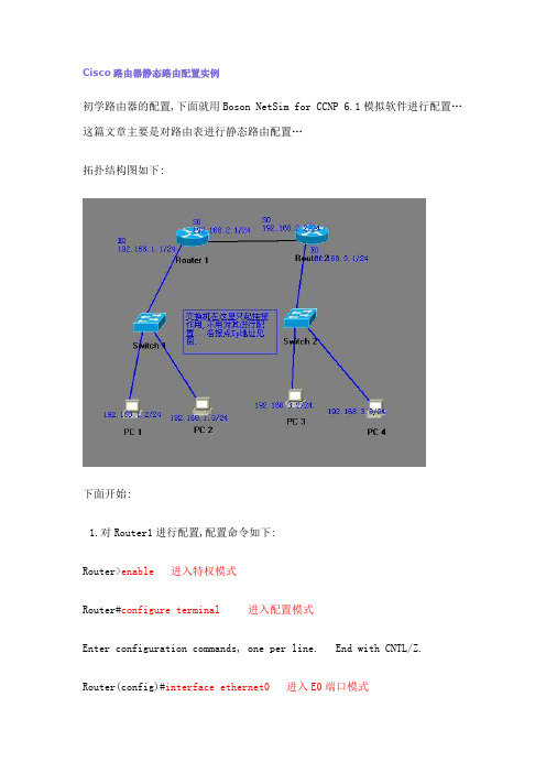
Cisco路由器静态路由配置实例初学路由器的配置,下面就用Boson NetSim for CCNP 6.1模拟软件进行配置…这篇文章主要是对路由表进行静态路由配置…拓扑结构图如下:下面开始:1.对Router1进行配置,配置命令如下:Router>enable进入特权模式Router#configure terminal 进入配置模式Enter configuration commands, one per line. End with CNTL/Z. Router(config)#interface ethernet0 进入E0端口模式Router(config-if)#ip address 192.168.1.1 255.255.255.0 配置IP地址Router(config-if)#no shutdown 激活该端口%LINK-3-UPDOWN: Interface Ethernet0, changed state to upRouter(config-if)#exit 返回上一级Router(config)#interface serial0 进入S0 端口模式Router(config-if)#ip address 192.168.2.1 255.255.255.0Router(config-if)#no shutdown%LINK-3-UPDOWN: Interface Serial0, changed state to up%LINK-3-UPDOWN: Interface Serial0, changed state to down%LINEPROTO-5-UPDOWN: Line protocol on Interface Serial0, changed state to downRouter(config-if)#clock rate 6400 注意这里是设置时钟..如有不明白,可以打”?”.但是系统给的参数是 64000 .而我们要配置成 6400 ..可能是模拟软件的一个小BUG 吧!现在是在模拟软件中,如果是真实环境,我们要参照说明书..按照说明书来配置参数….Router(config-if)#exitRouter(config)#ip route 192.168.3.0 255.255.255.0 192.168.2.2 配置路由表Router(config)#end 返回特权模式Router#show ip route查看路由表Codes: C - connected, S - static, I - IGRP, R - RIP, M - mobile, B - BGPD - EIGRP, EX - EIGRP external, O - OSPF, IA - OSPF inter areaE1 - OSPF external type 1, E2 - OSPF external type 2, E - EGPi - IS-IS, L1 - IS-IS level-1, L2 - IS-IS level-2, * - candidate defaultU - per-user static routeGateway of last resort is not setC 192.168.1.0 is directly connected, Ethernet0S 192.168.3.0 [1/0] via 192.168.2.2C 192.168.2.0 is directly connected, Serial02. 对Router2进行配置,配置命令如下:Router>enableRouter#configure terminalEnter configuration commands, one per line. End with CNTL/Z. Router(config)#interface ethernet0Router(config-if)#ip address 192.168.3.1 255.255.255.0Router(config-if)#no shutdown%LINK-3-UPDOWN: Interface Ethernet0, changed state to upRouter(config-if)#exitRouter(config)#interface serial0Router(config-if)#ip address 192.168.2.2 255.255.255.0Router(config-if)#no shutdown%LINK-3-UPDOWN: Interface Serial0, changed state to up/////在这儿我们就不用设置时钟了,在相连的两个路由器接口中,只要一个接口配置时钟就可以了Router(config-if)#exitRouter(config)#ip route 192.168.1.0 255.255.255.0 192.168.2.1Router(config)#endRouter#show ip routeCodes: C - connected, S - static, I - IGRP, R - RIP, M - mobile, B - BGPD - EIGRP, EX - EIGRP external, O - OSPF, IA - OSPF inter areaE1 - OSPF external type 1, E2 - OSPF external type 2, E - EGPi - IS-IS, L1 - IS-IS level-1, L2 - IS-IS level-2, * - candidate defaultU - per-user static routeGateway of last resort is not setC 192.168.3.0 is directly connected, Ethernet0C 192.168.2.0 is directly connected, Serial0S 192.168.1.0 [1/0] via 192.168.2.13.对计算机的配置..IP地址和子网掩码还有网关上面的图上面的..测试:PC1 ping PC3C:>ping 192.168.3.2Pinging 192.168.3.2 with 32 bytes of data:Reply from 192.168.3.2: bytes=32 time=60ms TTL=241Reply from 192.168.3.2: bytes=32 time=60ms TTL=241Reply from 192.168.3.2: bytes=32 time=60ms TTL=241Reply from 192.168.3.2: bytes=32 time=60ms TTL=241Reply from 192.168.3.2: bytes=32 time=60ms TTL=241Ping statistics for 192.168.3.2: Packets: Sent = 5, Received = 5, Lost = 0 (0% loss),Approximate round trip times in milli-seconds:Minimum = 50ms, Maximum = 60ms, Average = 55ms 静态路由表的配置完成..初学者…有错误希望大家指出…..。
- 1、下载文档前请自行甄别文档内容的完整性,平台不提供额外的编辑、内容补充、找答案等附加服务。
- 2、"仅部分预览"的文档,不可在线预览部分如存在完整性等问题,可反馈申请退款(可完整预览的文档不适用该条件!)。
- 3、如文档侵犯您的权益,请联系客服反馈,我们会尽快为您处理(人工客服工作时间:9:00-18:30)。
Web 或网络管 理服务器
7
通过Console口访问路由器
• 用计算机的串口对Cisco设备进行配置是最基本的 方法。 需要用专用配置电缆连接到设备的Console 口和计算机的串口:
8
通过Console口访问路由器
• 步骤 1:连接好计算机COM1口和路由器的 Console口; • 步骤 2:打开Windows自带的超级终端程序
R2的配置命令: Router> Router>enable Router#configure terminal Router(config)#hostname R2 R2(config)#interface fa0/0 R2(config-if)#ip address 10.1.1.2 255.255.255.0 R2(config-if)#no shutdown R2(config-if)#interface fa0/1 R2(config-if)#ip address 200.168.10.1 255.255.255.0 R2(config-if)#no shutdown R2(config-if)#exit R2(config)#ip route 202.128.1.0 22 255.255.255.0 10.1.1.1
Cisco路由器和交换机
路由器
交换机
3
路由器的硬件组成
• (1) CPU:中央处理单元,是路由器的控制和运算部件。 • (2) RAM/DRAM:内存,用于存储临时的运算结果,如:路由表、ARP 表、快速交换缓存、缓冲数据包、数据队列、当前配置。RAM 中的数 据在路由器断电后是会丢失的。 • (3) FLASH:可擦除、可编程的 ROM,用于存放路由器的 IOS,FLASH 的可擦除特性允许我们更新、升级 IOS 而不用更换路由器内部的芯片 。路由器断电后,FLASH 的内容不会丢失。FLASH 容量较大时,就可 以存放多个 IOS 版本。 • (4) NVRAM:非易失性 RAM,用于存放路由器的配置文件,路由器断 电后,NVRAM 中的内容仍然保持。 • (5) ROM:只读存储器,存储了路由器的开机诊断程序、引导程序和 特殊版本的 IOS 软件(用于诊断等有限用途),ROM 中软件升级时需 要更换芯片。 • (6) 接口(Interface):用于网络连接,路由器就是通过这些接口和不 同的网络进行连接的。
– 在 Windows 中的【开始】→【程序】→【附件】→【通信】菜单 下打开“超级终端”程序,在“名称”对话框中输入名称,例如 “Router”;按【确定】按钮。在“连接时使用”下拉菜单中选择 计算机的 COM1口,按【确定】按钮。
9
通过Console口访问路由器
• 步骤 3:设置通信参数;
• 步骤 4:路由器开机 ,观察路由器的开机过程。
• 路由器与计算机互联
– 通过局域网接口与网卡接口互联 – 使用双绞线(交叉线)
• 路由器与交换机互联
– 通过局域网接口与交换机接口互联 – 使用双绞线(直连线)
• 路由器与路由器互联(三种方式)
– 通过局域网接口互联,使用双绞线(交叉线) – 通过广域网串口互联,使用DTE和DCE串口连接线 – 通过高速网络互联,使用光纤接入 11
路由器的广域网连接配置
• 网络层数据在通过广域网链路传输之前都会封装 成帧,需要配置适当的二层封装类型。
– HDLC
• 由ISO开发的面向比特的同步数据链路层协议。 • 不提供身份验证,缺少对链路的安全防护。
19
静态路由配置命令
• 配置静态路由的命令为“ip route”:
– ip route 目的网络 掩码 {下一跳地址 | 接口}
• 举例:
– R1(config)#ip route 210.1.1.0 255.255.255.0 200.1.1.2 //手工配置路由表项 – R1(config)#no ip route 210.1.1.0 255.255.255.0 200.1.1.2 //手工删除路由表项 – R1#show ip route //查看路由表
• 【Tab】键的使用
Router>en【Tab】//使用【Tab】键帮助我们自动补全命令 Router>enable
17
使用IOS命令对路由器进行基本配置
Router>enable Router#configure terminal //进入全局配置模式 Router(config)#hostname R1 //配置路由器的名称为“R1”,设置立即生效 R1(config)#interface fastEthernet0/0 //进入到接口模式,这里是百兆以 太网口(第 0 个插槽的第 0 个接口,编号从 0 开始)。 R1(config-if)#ip address 10.1.1.1 255.255.255.0 //配置 IP 地址和掩码 R1(config-if)#no shutdown //开启以太网口,默认时各个接口是关闭的。 R1(config-if)#exit //退回到上一级模式 R1(config)#interface Serial0/0/0 //进入到接口模式,这里是串行接口 R1(config-if)#ip address 10.12.12.1 255.255.255.0 //配置 IP 地址和掩码 R1(config-if)#no shutdown //开启接口 R1(config-if)#end(或【Ctrl+Z】 ) //结束配置直接回到特权模式下。 R1#show ip interface brief //显示接口的IP地址、地址获得方法和状态 R1#show running-config //查看当前配置 18 R1#ping 10.1.1.2 //测试连通性
6
Cisco设备的多种配置方法
Telnet 端口
虚拟终端
TFTP
控制端口
Aux 端口 PC or Unix服务器
• • • • •
用Console口接终端配置 在Aux口接一个MODEM同电话网相连,在远端进行配置 在TCP/IP网上可通过仿真终端Telnet配置 可以从TFTP Server上下载配置 可用网管工作站进行监控和配置
– (1) 用户模式:通常用来查看路由器的状态。在此状态下,无法 对路由器进行配置,可以查看的路由器信息也是有限的。
– (2) 特权模式:可以更改路由器的配置,也可以查看路由器的所 有信息。
5
Cisco路由器的启动过程
• (1) 执行 ROM 中的引导程序加载(Bootstrap Loader),把 IOS 装到 RAM 中; • (2) IOS 可以存放在许多地方(FLASH、TFTP 服务器上或 ROM 中),路由器寻找 IOS 映像的顺序,取决于配置寄存器的启 动域以及其他的设置。 • (3) 加载 IOS 到 RAM 中:如果 IOS 是压缩过的,就先解压。 • (4) 在 NVRAM 中查找配置文件,并把配置文件加载到 RAM 中运行。 • (5) 如果在 NVRAM 中没有找到配置文件, 就进入 setup 配置模式
双绞线 Unshielded Twisted Paired (UTP)
线对 T 代表发送 R 代表接收 线对2 T2 线对2 R2 线对3 T3 线对1 R1 线对1 T1 线对3 R3 线对4 T4 线对4 R4
针 1 2 3 4 5 6 7 8
1
8
RJ-45 连接器
12
直连线 VS. 交叉线
– 在特权模式下输入相应的命令时进入 – 例如:interface fastEthernet0/0 router(config-if)#
16
IOS命令的使用
• “?” 的使用 (以配置路由器时钟为例)
Router#cl? //列出当前模式下可以使用的以“cl”开头的所有命令 clear clock Router#clock ? //列出当前模式下可以使用的以“clock”开头的所有命令 set Set the time and date
Cisco路由器的基本配置 静态路由 广域网连接(串行的点对点连接)
内容
•
– – – –
Cisco路由器简介
路由器的硬件组成 IOS简介 路由器的启动过程 配置路由器的方法
• • • • •
Cisco路由器与其它设备的连接 IOS命令的使用 使用IOS命令对Cisco路由器进行基本配置 Cisco路由器的静态路由 路由器的广域网连接配置
静态路由
• 由网络管理员在路由器上手工添加路由信息以实 现路由目的。 • 作用
– 在不会显著增长的小型网络中,使用静态路由便于维 护路由表。 – 静态路由可以路由到存根网络,或者从存根网络路由 到外部网络。
– 使用单一默认路由。如果某个网络在路由表中找不到 更匹配的路由条目,则可使用静态路由作为通往该网 络的路径。
直连线
交叉线
8 1 8
1
8 1
1
8
8
1
8
1
8
18Βιβλιοθήκη 1棕 棕 绿 蓝蓝 绿 橙 橙 白 白 白 白
棕 棕 绿 蓝蓝 绿 橙 橙 白 白 白 白
棕 棕 绿 蓝 蓝 绿 橙橙 白 白 白 白
棕 棕 橙 蓝蓝 橙 绿 绿 白 白 白 白
两端的线序相同
部分线序交叉
13
串行连接中的DTE和DCE
Data Terminal Equipment 数据终端设备
• WAN连接中用户方的最后设备
Data Communications Equipment 数据通讯设备
• WAN服务商方的最后通讯设备 • DCE提供时钟 调制解调器 通道服务单元/ 数据服务单元
DTE
S S S S
DCE
S
DTE
DCE
S