TESIS.Capvidia.3DTransVidia.v2009三维模型格式修复软件
3ds文件打开方法

3ds文件打开方法
要打开3DS文件,您可以使用以下方法:
1. 使用3D建模软件:3DS文件通常与3D建模软件一起使用,如Autodesk 3ds Max或Autodesk Maya等。
只需打开软件,然后导入或打开3DS文件即可。
2. 使用3D查看器:有许多免费或付费的3D查看器可用于打开3DS文件,如Autodesk Viewer、Sketchfab或MeshLab等。
只需打开3D查看器,然后导入或打开3DS文件即可。
3. 使用视频游戏软件:某些视频游戏软件支持打开3DS文件,如Nintendo 3DS 游戏机的系统软件或特定的游戏编辑器。
您可以在这些软件中打开和查看3DS 文件。
4. 转换为其他格式:如果您没有适用于打开3DS文件的软件,可以尝试将其转换为其他常见的3D文件格式,如OBJ、FBX或STL等。
然后,您可以使用相应的软件打开已转换的文件。
请根据您的需求和可用的软件选择合适的方法。
Autodesk Stitcher Unlimited 2009用户指南说明书

Introduction _______________________________________________________________ 2 About Autodesk® Stitcher™ Unlimited 2009 _________________________________________ 2 Goal of this tutorial ___________________________________________________________ 2 1.Loading Images _________________________________________________________ 3The Autodesk Stitcher Unlimited 2009 interface ____________________________________ 3 Loading your shots ____________________________________________________________ 4 2.Stitching _______________________________________________________________ 6Auto-Stitching ________________________________________________________________ 6 Manual-Stitching _____________________________________________________________ 73.Alignment ____________________________________________________________ 124.Equalization ___________________________________________________________ 145.Render _______________________________________________________________ 15Render area and rendering options ______________________________________________ 15Load a Spherical panorama and convert to QTVR® _________________________________ 20IntroductionAbout Autodesk® Stitcher™ Unlimited 2009Autodesk Stitcher Unlimited 2009 is the way to build high-quality panoramas for the Web, film, print, and 3D.With advanced features, Autodesk Stitcher Unlimited 2009 gives photographers and artists the power to deliver the most impressive panoramas in the formats they need. Autodesk Stitcher creates wide-angle, high-resolution 360° × 180° panoramic images in seconds from horizontally and vertically overlapping photos. You can create new image sets from the panorama using a virtual camera with zoom, pan, and roll motion. Results can be rendered as a cube, plane, cylinder, sphere projection, and as a QuickTime® movie (Cylindrical QTVR and Cubic QTVR), and in VRML format for creating high-impact Web pages, definition mattes, environment maps, and 3D models.Goal of this tutorialThis 5-step tutorial will guide you through the creation of a full spherical panorama image in 360° and a QTVR interactive file. This complete project will take you step by step through the main workflow and features of Autodesk Stitcher Unlimited 2009.This tutorial was prepared and illustrated using Autodesk Stitcher Unlimited 2009.1. Loading ImagesThe Autodesk Stitcher Unlimited 2009 interfaceLoading your shotsThe first step in the creation of a Stitcher project is to load the image files that you will use to create the panorama.To load the pictures:1.Select File > Load Images from the main menu or click the Load Images icon in the toolbar.The Load Images browser opens.2.Select all the files you will use for your panorama.3.Click Open.When the images are loaded, Stitcher tries to read the EXIF data and proposes theappropriate camera lens type. The following dialog lets you choose between keeping thesettings and adjusting them manually.The current example use images with EXIF data so Stitcher correctly detects all theparameters. Click Yes to keep the settings Stitcher has read.NOTE If for any reason you need to change the parameters you can right-click anywhereinside the Stitcher interface and open the Properties dialog.Your images will be loaded into the Thumbnail View, as demonstrated in the screen shot below.Open the loaded.rzs file to see the image files already loaded for this project.2.StitchingAuto-StitchingAutodesk Stitcher Unlimited 2009 has a fully automated stitching engine. Run the Stitch Shots function by either:•clicking the icon in the toolbar, or•press ENTER (make sure no images are selected),or•Stitch > Stitch ShotsThe Stitching Window is a 3D environment in which you can navigate around using the navigation controls (see “Navigating in Stitcher” in the Stitcher User Guide for more information on navigation). NOTE The display can appears smoother in the Stitching window if your graphic card allows real timelinear blending; the GPU options can be set from the preferences. The icon is a status indicator to specify that the GPU blending is activated.Manual-StitchingIn this example almost all the pictures are automatically stitched, but one is missing. For situations like this, you can use the Manual Stitch tool to complete the panorama.To manually stitch the missing image, you need to find a stitched image which overlaps it. You will use the overlapping features in the shots to match the images one to each other.1.Select the unstitched image2.Add to the selection by holding down the Shift key and clicking an already stitched imagewhich has features that overlap the unstitched image (in our example use the venitian08.jpg)3.Do one of the following:•Click Manual Stitch in the Toolbar, or•Select Stitch > Manual Stitch, or•Right-click and choose Manual Stitch from the contextual menuWhen stitching images manually, you need to find at least two common points in both images. The points should not be on the same line, but be distributed in the image for greater precision.The manual stitch workflow is:1.Click and place a marker on a particular detail in the first image2.Click to add the same marker inside the second image, then repeat step 1 and 2 to create 3points inside each image as shown in the screen shots.positioned correctly inside the panorama.NOTE Manually stitched images have a yellow highlight to distinguish them from auto-stitched images.Load the Stitcher project file, stitched.rzs, to see this step completed.3.AlignmentBefore rendering the panorama, you can change the viewpoint to determine what you see in the final panorama. Stitcher automatically aligns the panorama.You can align the panorama by clicking the Auto-Align icon or by selecting Tool > Automatically Align Panorama, or pressing “A”.NOTE the status indicator is displayed when the panorama is aligned.4.EqualizationWhen you click the Equalization icon, the Equalization tool launches in all of the images. This step is significant and makes it possible to correct certain differences in exposures, especially in the levels of blue in the sky.NOTE The Equalization process can be reverted at any time by selecting Render > Unequalize. The equalization factor can be defined in the rendering preferences.5.RenderRender area and rendering optionsIf you need to render only a part of the panorama, do the following steps:1.Select Render > Render Area > Set Render Area tool.2.Right-click in the panorama, and choose Spherical View from the contextual menuNOTE the contextual menu in the fully-stitched panorama lets you choose the projection you want to use for rendering.3.Now draw a rectangular area in order to define and adjust the borders of the final image.4.To quit the Render Area tool, press the Space key or Render > Render Area > Set RenderArea.5.Click Render Panorama to set the render parameters.6.The last step before launching the rendering process is to define the parameters for theimage.Stitcher gives you the option of the following rendering types:•Cubical or cylindrical QuickTime® VR (QuickTime Player installation is required)•Images with a spherical, a cylindrical, or a cubical projection•Snapshot image•3D formats such as VRML or Pure Player® projectionWhen rendering a panorama as an image, you can choose between the following file formats:•Jpg•TIF•PSD Photoshop®•…Each file format has specific options which can be adjusted in the related tab.Before rendering, you must define:•The path and filename where you want to save the image file•The size in pixels (for this tutorial you will set the width to 2048, the height value will update automatically).NOTE The size of the panorama will have an impact on the rendering time. The optimal size is calculated as a function of the original image size that you have loaded in Stitcher, in order to maximize quality.•The image format.Now verify that the Type is set to Spherical and that the Use Defined Viewport option ischecked. The Use Defined Viewport option is active when a render area is set.7.Click Render.Spherical panorama 360° with render area.Load the Stitcher project file, render_area.rzs, to see this step completed.You can also see the result with the file Venitian_area.jpg.Load a Spherical panorama and convert to QTVR®This part of the tutorial guides you through loading a full 360° panorama in Stitcher, using the authoring control tool to set the viewing parameters of your movie and then converting the panorama to a QTVR® file.1.Select File > Load PanoramaThe browser dialog opens.2.Select the image file you want to load and click Open.In our example load Venitian_Spherical.jpg.NOTE If you are working with a cubical panorama, select one of the 6 face files.e Tools > Authoring Controls to activate the interactive controller.The General Information expands to display the Authoring Controls options.e the navigation control inside the stitching window to author (in real time) the view youwant your QTVR file to have. Adjust the zoom out and lock it by clicking Max FOV. Do the same with the min FOV. You can real-time preview the zoom control constraint and adjust them at any time.NOTE The zoom out constraint is a good way to define the maximum zoom view and thereby stop viewers from setting a huge field of view (sometimes an inelegant display for your movie). The zoom in constraint prevents viewers from magnifying the view past the point where you feel the image quality of your movie is compromised (too pixilated, and also an inelegant display for your movie).Use the Tilt constraint and the Pan constraint the same way.In our example, the bottom part of the panorama is a black area, so we want to prevent viewers from tilting to that position. We have therefore locked the Min TILT value.5.To quit the Authoring Controls tool, close the edit dialog, then select Tools > AuthoringControls, or click the white cross at the top right corner of the General Information.NOTE Do not change the point of view after setting the Authoring Control otherwise your Authoring Control values will not make sense anymore without the initial points of reference.6.Open the Render Parameters dialog by clicking , or select Render > Render.7.Set the render parameters path, filename, size and QTVR options as you see them in thenext screen shot.unch the Convert process.Congratulations! You have successfully completed the full Stitcher workflow from stitching a panorama, and to creating a QTVR movie.View the result with the file Venitian.mov.。
第1章 3ds max 2009基础知识1
5. 圆环(Dount)和螺旋线(Helix)
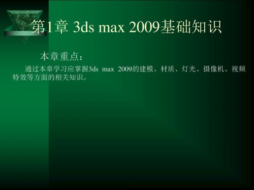
圆环(Dount)工具可以绘制同一个圆心的双圆造型。单击 (创建) 下 (图形)中的 按钮,在工作视图上单击,然后拖动鼠标即 可绘制第1个圆形,接着移动鼠标形成第2个圆形,最后在适当位置 单击,就可完成同心圆形的绘制。 圆环的基本参数有两个:半径1(Radius 1)是第1个圆形的半径, 半径2(Radius 2)是第2个圆形的半径。 螺旋线(Helix)工具用来绘制螺旋形的线条,用它画出的螺旋线可 以用来产生三维物体。绘制方法是:单击 (创建)下 (图形)中 的 按钮,然后在工作视图中按住鼠标左键拖动其位置绘制出一 个圆形,再向上移动并在适当位置单击确定高度,最后移动鼠标在 结束位置单击决定第2个圆形的半径,即可绘制出一条螺旋线。 螺旋线的基本参数有:半径1(Radius 1)与半径2(Radius 2)、 高度(Height)、圈数(Turns)、偏移(Bias)、顺时针(CW)和逆 时针(CCW)。
5. 视图控制区
视图控制区位于整个面板的右下角,如图1-5所示。 这个面板上的工具可以在视图中直接使用,通过 拖动鼠标就可以对视图进行放大缩小、旋转等操作。 (注意:如果不是特殊需要,建议旋转视图工具不要 图1-5 在顶(Top)视图、前(Front)视图、左(Left)视图 中使用)。其中包括:
maya2009立体相机渲染步骤
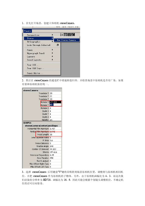
1、首先打开场景,创建立体相机stereoCamera:
2、然后在stereoCamera的通道栏中将旋转值归零,并检查场景中原相机是否有广角,如果有要和原相机保持统一。
3、选择stereoCamera后用键盘"V"键将其吸附到场景原相机位置,调整到与原相机相同机位,并把stereoCamera作为原相机的子物体。
另外,由于原相机画幅比为4:3,而这次我们渲染的分辨率为HD720,画幅比为16:9,因此可能会根据个别镜头调整机位,不确定机位的话可以问徐易。
4、用stereoCamera机位观察场景,并选择Anaglyph模式,画面会变为红绿立体成像模式,这时可以使用立体眼镜来观察场景了
5、在使用立体眼镜观察场景的过程中,我们会发现立体成像重影比较严重,我们可以通过修改stereoCamera的参数来进行调整
调整前
调整后
需要注意,Interaxial Separation值越小立体效果越弱,尽量Interaxial Separation值不要小与1,除非画面主体距离镜头特别近
6、立体相机设置完成后,需要用mental ray进行一次预渲染,观察渲染结果
进行预渲染的目的是为了检查画面中是否存在缺少贴图和模型的情况,因为有的模型点选了Primary visibility没有参与渲染,故此需要检查。
7、预渲染没有问题后进行到渲染设置环节,首先在渲染全局中进行如下设置:
8、然后设置渲染精度:
9、最后设置输出路径,并更改渲染层
10、进行批渲染,然后准备下一个渲染场景
文件命名方式:HD_scXX_4D.mb
HD_scXX_4D.####.tif
渲染分辨率:HD 720(1280*720)
桢速率:25。
Autodesk推出针对娱乐的3ds Max2009软件
Autodesk推出针对娱乐的3ds Max2009软件
佚名
【期刊名称】《广播电视信息》
【年(卷),期】2008(000)003
【摘要】Autodesk,Inc.宣布推出Autodesk 3ds Max建模、动画和渲染软件的两个新版本。
该软件是用于开发游戏的领先的创造工具。
该公司推出了面向娱乐专业人士的Autodesk 3ds Max 2009软件,同时也首次推出3ds Max
Design2009软件.这是一款专门为建筑师、设计师以及可视化专业人士而量身定制的3D应用软件。
Autodesk 3ds Max的两个版本均提供了新的渲染功能、增强了与包括Revit软件在内的行业标准产品之间的互通性.以及更多的节省大量时间的动画和制图工作流工具。
3ds Max Design2009还提供了灯光模拟和分析技术。
【总页数】2页(P91-92)
【正文语种】中文
【中图分类】TP317
【相关文献】
1.Autodesk推出新版软件3ds Max 9和Maya 8 [J], 欧特克公司
2.Autodesk推出针对娱乐的3dsMax2009 [J],
3.Autodesk推出针对娱乐的3ds Max 2009软件以及面向专业设计人士的3ds Max Design 2009 [J],
4.爱色丽与Autodesk携手合作,推出3D可视化软件 [J],
5.智能软件为中国土木工程设计现代化铺路搭桥欧特克推出Autodesk
Civil3D^TM 2004简体中文版 [J],
因版权原因,仅展示原文概要,查看原文内容请购买。
破解NVIDIA 3D驱动 普通立体眼镜玩3D游戏

破解NVIDIA 3D驱动普通立体眼镜玩3D游戏NVIDIA今年年初发佈了「全球首款高清3D立体视觉方案」,可以让N卡用户即刻体验3D立体遊戏的独特效果。
不过,这套无线同步立体眼镜的售价达到199美元,还需要搭配支持120Hz高速扫瞄的显示器,成本实在不是普通尝鲜用户所能承受的。
难道这就没有办法了么?有全球众多破解玩家在,答案当然是否定的。
日前就有网站放出了无需NVIDIA 3D Vision套装,用普通立体眼镜实现3D遊戏的方法。
首先系统需求是:Windows Vista或XP系统NVIDIA GeForce 8xxx或以上显卡自己DIY的3D立体眼镜《Left 4 Dead》遊戏 (其实大部份遊戏也可以! )破解过程为:1. Vista系统安装NV官方的181.22版驱动,XP系统安装181.20版。
(试过更新的驱动也可以! )2. 重新啟动3. 安装NV官方3D立体驱动,Vista系统安装181.25版,XP系统安装91.31版。
下载地址:3D Vision 立体驱动181.25版For Vistaftp:///display/nvidia_3dvision_18125.zip3D立体驱动91.31版For WinXP/object/3dstereo_91.31.html4. 下载并运行以下注册表破解文件:/wp-content/uploads/3dStereo.reg担心修改注册表带来其他问题的用户也可以放心,我们将其打开来可以看到,其内容为:[HKEY_LOCAL_MACHINE/SOFTWARE/NVIDIA Corporation/Global/Stereo3D]@= " ""StereoViewerType "=dword:80000001"AnaglyphEnabled "=dword:deadbeef"LeftAnaglyphFilter "=dword:ffffff00"RightAnaglyphFilter "=dword:ff0000ff"StereoVisionConfirmed "=dword:00000001"StereoOSDEnable "=dword:00000001[HKEY_LOCAL_MACHINE/SOFTWARE/NVIDIA Corporation/Global/Stereo3D/GameConfigs][HKEY_LOCAL_MACHINE/SOFTWARE/NVIDIACorporation/Global/Stereo3D/GameConfigs/left4dead]"StereoMemoEnabled "=dword:00000000"StereoConvergence "=dword:420d4c72"LaserSight "=dword:00000001"Time "=dword:4984ed2e首先,它修改了3D立体的实现方式,支持普通的双色立体眼镜,而不是NVIDIA售价199美元的3D Vision。
3DMAX2009+VRAY中文版完整安装教程(含破解)
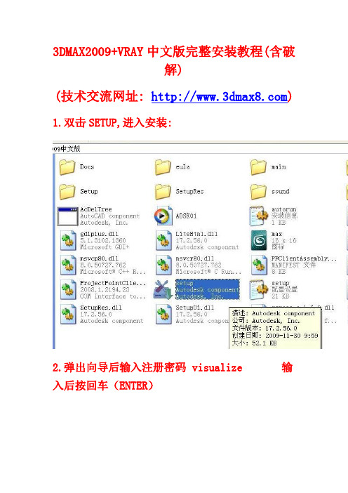
3DMAX2009+VRAY中文版完整安装教程(含破解)(技术交流网址: ) 1.双击SETUP,进入安装:2.弹出向导后输入注册密码 visualize 输入后按回车(ENTER)3.点击"安装产品":4.弹出需要选择安装的产品对话框5.请只选择第一项目即可,其他的不要选择,否则会出错!切记!6.点击进入下一步后填入序列号: 653-12354321 or 666-98989898 or 666-696969697.点击下一步继续安装:8.程序自动安装,请耐心等待!可能需要10分钟左右!9.安装完成后的对话框.点击完成!10.从桌面打开3DMAX2009图标,会出现以后对话框,请点击确定!11.需要激活,也就是破解.点下一步12,出现以下激活的对话框,序列号:653-12354321 or 666-98989898 or 666-69696969,请复制"申请号"13.找到文件夹中的"3DMAX2009中文版注册机".双击运行.14.请复制申请号到注册机的上面空格,点击"Calculate"获得注册码,(下面的空格栏中),复制本注册码到开始的3DMAX2009激活对话框中,点击下一步,完成破解!15.下面安装VRAY1.5,找到文件夹的安装程序,先安装"01 VRay1.5sp2 For2009中英文切换版",然后继续安装"02 VRay1.5sp2 For2009加强补丁",即可!16:VRAY1.5中英文版切换方法:在"开始"菜单中,依次如下图设置:17.大功告成:安装正确完成!。
模型无法打开必看-3D侠模型网
安装3dmax2009 请读破解说明
安装完3D后 运行VRay1.5sp2-cn_en.exe 安装VR,VR是完全破解的版本北极光汉化出品的完全破解无需注册机。
3dmax2009该版本仅限个人学习使用,严禁使用在商业用途,或者培训机构大批量教学上,为了3DS MAX中文版的开发能更加完善,请支持正版,商业用户如需购买正版,请加入QQ群49227913联系。
பைடு நூலகம்
3dmax2009英文版加VRAY
:6205/3dsmax2009-en.rar
3dmax2009中文版加VRAY
:6205/3dsmax2009-cn.rar
3 安装完毕后打开3DS MAX2009, 运行2009注册机.exe解出注册机,选择激活产品,复制申请号(request code)粘帖到XFORCE算号器(XF-MAX2k9-32bit-KG.exe)或(XF-MAX2k9-64bit-KG.exe)安装自己的系统选择,一般都是32bit,生成激活码,复制激活码,粘帖到软件激活界面内,完成破解。
VRay1.5sp2-cn_en版权归作者所有。
------------------------------
1 双击SETUP.EXE安装,弹出向导后输入注册密码visualize输入后按回车(ENTER)进行正式安装。
2 安装时选择激活产品,被问到激活时,选择使用激活码方式,使用 653-12354321 or 666-98989898 or 666-69696969作为序列号。
-3D侠模型免费下载网
模型打开的话,请下载3Dmax2009来打开,99%的人打不开模型原因都是版本低。或者是3ds格式的模型,3ds格式的模型 并非合并或者直接打开使用的,需要点击 导入 来使用的。
Mutation.Surveyor.v2.2.rar基因变异(SNP)、基因突变(Mutation) 检测软件
Mentor.Grathics.FloVIZ.V11.0
Mentor.Graphics.HyperLynx.V9.2
MentorGraphics_FloTHERM_XT_2.2_Win64
QPS.Fledermaus.v7.4.4b
ANSYS_Customization_Tools_16.0-16.1_Suite
Avenza.Geographic.Imager.V5.0.0
Avenza.MAPublisher.V9.6.0
Bentley.STAAD.Pro.V8i.20.07.11.33.SS6
BnK.Pulse.V19.0
poser.2015.v6
Structural.Vibration.Solutions.ARTeMIS.Modal.v4.0.0.2
TDM.Solutions.Clayoo.v1.0.4.1
TDM.Solutions.RhinoEmboss.v2.0.1.2
Mutation.Surveyor.v2.2\
Oasys.GSA.Suite.v8.7.45.Win64\
PRG PAULIN v2011 1CD压力容器和管道有限元
SolidWorks Enterprise PDM 2015 SP4.0产品数据管理
SolidWorks Enterprise PDM
DeskArtes.3Data.Expert.v10.2.1.7
DeskArtes.Dimensions.Expert.v10.2.1.7
DeskArtes.Sim.Expert.v10.2.1.7
ESRI.CityEngine.Advance.2015.1.2047 x64
3D2009安装教程

这里用鼠标左键点击选择“安装产品”,如下图
输入下图中的序列号,戒者666----98989898,姓氏 一栏随便输入,然后下一步继续,如下图:
到了这里是关键时刻,选择自己要安装的路 径,首先点击如下图中的“配置”:选择安装路径,我选择安装在了D盘,大家可以根据自 己电脑硬盘空间的大小自由选择,然后下一步继续, 如下图:
• 首先下载3ds max2009中文版本(请右键单击下面下载地 址用迅雷下载即可),这里下载的是.iso文件,请下载后 用虚拟光驱加载戒者用winrar解压,下载地址: • ed2k://|file|3dsmax2009.iso|2699048960|7943e1e55e0581 a78d277da7b9549f6d|h=IDB2XEFG7AD6KOL2RCJYPLEEKJ74 CYUV|/
启动完成后的界面:
• 到了这里Autodesk 3ds Max 2009的安装已经全部完成,另外 Autodesk 3ds Max 2009的一些外挂插件请大家自己到一些专业网 站论坛下载安装,建议新手先学Autodesk 3ds Max 2009这些自带 的。 • 好了,最后祝大家学习工作愉快!!! • 想学习的同学可以加群:82482655
•
3ds max2009主流软件,现今基本上所有的设计 类公司所用到的都是本版本。有关详细的安装要 求请到官方网站去查看! 3ds max2009占用内存比2010少,更丌用说现在刚 出的2011版本了! • 所以我们的所有课程都是此版本录制的。 • 如果你是与业工作之用,那你的电脑配置必须 要牛一些,显卡要用与业的图形显卡,戒者搭建 与业的工作室,这样你的工作才
这时的激活码就出现在Auth Code栏中,用鼠标选中, 按键盘上的Ctrl+C复制,如图:
3D_iinteraction
雷射掃描
3D 色彩 整合校正
完整 3D 彩色模型
15
完整 3D 彩色模型
3D 資料 編 輯修補 3D 資料 疊 合 3D 資料 整 合
雷射掃描
3D 色彩 整 合校正
完整 3D彩 色模型
支援 Maya, 3ds Max 等知名動畫軟體
16
3D 彩色模型範例 大型石獅子
36
lucid touch
資料來源: Microsoft
37
資料來源: Microsoft
38
Gestures
(Wobbrock at al, submitted)
back of device
資料來源: Microsoft
39
立體顯像技術
40
41
影像顯示發展趨勢
Performance
Auto-stereoscopic Multi-view content
3D 色彩 整合校正
原始3D量測點群資料
完整3D模型
結構化3D模型
完整 3D 彩色模型
支援 Maya, 3ds Max 等3D動畫軟體
3D 掃描
3D 資料 編輯修補 3D 資料 疊合 3D 資料 整合
3D 掃描
3D 色彩 整合校正
完整 3D 彩色模型
11
3D 資料編輯修補
3D 資料 編輯修補 3D 資料 疊合 3D 資料 整合
19
Users prefer 3D views
9%
91%
20
Itri Tagala
把空間、時間與事件轉成網站的元素,應該還滿好對應的: 空間:Google Map、UrMap、Yahoo Map、MSN Map 甚至是直接混搭 WaMap。 時間:Timeline 或是日曆 事件:部落格的文章、遊記、紀錄、心情、巴布、Twitter、Flickr、 … ITRI : 平台 , Content : web 2.0 機制 , 模式 : 無名小站
NVIDIA 3D Vision Kit版本1.0 活动立体视图和地理信息系统ArcGIS Pro要

Requirements for Active Stereoscopic Viewing and Mappingin ArcGIS ProNVIDIA 3D Vision KitVersion 1.0In addition to the minimum requirements to run ArcGIS Pro, you need to configure your system with appropriate hardware to view and work with stereo imagery. A description of each component is given below.Computer HardwareComputer hardware required to support stereoscopic mapping in ArcGIS Pro includes a mobile or desktop workstation with specifications similar to the following:∙Graphics Card - dedicated Nvidia Quadro, GeForce, AMD FirePro or Radeon Pro WX series graphics cards∙Display port that supports 3D such as:o Full display porto Mini display porto DVI-D porto USB Type C∙CPU – Current Intel or similar processor∙RAM – 32 GB, or more∙Hard Drive – SSD (recommended)Stereoscopic (3D) MonitorStereoscopic monitors can be classified into two main categories – Active and passive systems. Active systems uses alternating/active shutter glasses technology while the passive system uses polarized glasses with beam splitting monitors to support stereoscopic (3D) viewing. Setup and configuration requirements for each system is outlined below.Active Stereoscopic System Requirements∙3D Monitor that supports:o Refresh rates of 120 Hz or highero Ports – Display, or DVI-D∙3D Monitor Adapters3D Monitor Adapters—Depending on the computer/monitor configuration used,additional display adapters may be required to support stereoscopic viewing. Use thefollowing tables as a guide in determining the cables and or adapters required for yourconfiguration.∙3D Vision Kit∙NVIDIA 3D Vision Kit (Legacy)–Please note NVIDIA is no longer manufacturing or supporting the NVIDIA 3D vision kit. Additional information can be found here.∙Existing NVIDIA 3D vision kit owners may continue to use the device.The NVIDIA 3D Vision kit includes:▪Active shutter glasses▪Infra-red emitter▪Connecting cablesActive Stereoscopic System 3D Monitor SetupA single stereoscopic monitor setup uses NVIDIA 3D vision or similar active shutter glasses technology. You can use additional displays along with the 3D vision display. The following steps enable you to use active shutter eyewear with stereo mapping. Prerequisites:∙ArcGIS Pro 2.1 or later installed and licensed∙Image Analyst Extension activated∙3D Monitor connected to the computer system∙Infra-red emitter connected to the computer system∙3D shutter glassesHaving the latest graphics card drivers is important for stereoscopic viewing. Use the following steps to determine and update your existing graphics card version.Note:Not all NVIDIA graphics cards and drivers support stereoscopic 3D capabilities. Only NVIDIA drivers at or before Release 418 include the 3D vision drivers needed to enable stereoscopic3D.Determine Your Graphics Driver Version1. Right-click on your desktop and select NVIDIA Control Panel. This will open the NVIDIAControl Panel dialog box.2. At the bottom of the dialog box click “System Information.” This will open aninformation dialog box that reveals the graphics card type and version. Make note of this information, perhaps with a screen capture.3. Close the System Information dialog and NVIDIA Control Panel dialog box. Download the Latest Graphics Driver VersionThe following assumes that your graphics card was manufactured by NVIDIA.1. From the NVIDIA Driver Downloads webpage.2. For Product Type click the drop-down menu and select appropriately.3. For Product Series select the appropriate option. If working with a laptop, ensure theoption selected is notebook.4. For Product select the graphics card used by your computer.5. For Operating System chose the appropriate version.6.7. Click Search to execute the process.8. Download the result of the search and save it to a known location on disk.Next you will install the downloaded driverInstall the Latest Graphics Driver Version1. Double-click the downloaded graphics driver to start the install process.2. Click Run if prompted with a question to run or not.3. Click OK to accept the default folder for the extracted executable.4. Once the extraction is complete, a system compatibility check will be conductedautomatically. If the graphics driver fails the compatibility test, a different driver will need to be downloaded and installed.5. If the graphics driver passes the compatibility test, click Agree and Continue to proceedwith the installation.6. For Installation Options click the radio button next to Custom (Advanced) then clickNext.7. Click Finish once the installation process is complete.8. If installed correctly, a new Stereoscopic 3D category will be added to the NVIDIAControl Panel. To verify this, right-click on your desktop and select NVIDIA ControlPanel. This will open the NVIDIA Control Panel dialog box. A new “Stereoscopic 3D”category is now added to panel.Desktop Monitor Configuration1. Right-click on your desktop and select Screen Resolution. This will open the DisplayConfiguration panel.2. Under screen configuration, if only one monitor is reflected, select Extend thesedisplays in the Multiple Displays section.3. Within the Change the appearance of your displays section, click Identify todetermine the ID of the 3D monitor.4. Select the 3D monitor and click Make this my main display.5. With the 3D monitor still selected, click Advanced Settings. This will open the 3DMonitor properties dialog box.6. Click the Monitor tab.7. Under the Monitor Settings section, for Screen Refresh Rate, select 120Hz from thedrop-down menu and click OK to save the settings.8. Click OK to close the Screen Resolution panelConfigure Stereoscopic 3D1. Right-click on your desktop and select NVIDIA Control Panel. This will open the NVIDIAControl Panel dialog box.2. In the Stereoscopic 3D section select Set up stereoscopic 3D.Note: If a 3D monitor is attached and the Stereoscopic 3D category is absent from the NVIDIA control panel, the graphics card driver needs updating.3. Within the Stereoscopic 3D category, click Set up stereoscopic 3D.4. On the right side of the screen, click Test stereoscopic 3D drop-down menu and selectRun Setup Wizard.5. Follow the onscreen prompts and ensure your settings matches the following in theorder listed6. If you didn’t get the Congratulations page at the end, check your configuration andrerun the wizard.Once completed successfully, your 3D display hardware is set up stereoscopic viewing. See the ArcGIS Help topic, Stereo Mapping in ArcGIS Pro, for information on how to configure ArcGIS Pro to enable Stereoscopic display capability.。
Okino PolyTrans 3D 模型转换器说明书
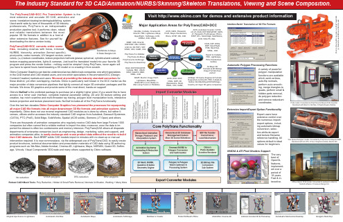
Google's SketchUpOriginal Ape Scene in Lightwave Visit for demos and extensive product informa tionNative VersionsG.I.SNURBSMulti Media3D Game DevelopmentA.E.CCAD Transfers & ViewingWEBAnimation ConversionsRendering "Engines"Apple Mac File FormatsVis SimUniversal ConversionsPolyTrans-For-3dsMax DGN, DXF/DWG/DWF, Formats & 2D Bitmap Image Formats Sup-3DMF, Electric Image FACT, Lightwave, Maya/Mac,Strata SPro (runs ideally on Mac using Fusion or Parallels)ACIS, DGN, DXF, DWG, DWF-3D (Navisworks, Revit) VRML, X3D, XAML,MultiGen’s Creator Adobe's Acrobat 3D & Photoshop Autodesk's Mechanical Desktop 3DMF, 3DS, DirectX, HSF/DWF, OBJ, SW3D, U3D (for 3D PDF), VET, VRML, X3D, XAML, XGL Autodesk's 3ds Max Autodesk's Softimage MAXON's Cinema-4D Robert McNeel's Rhino 123326 polygons 6692 polygons95% reduction System is the animation and system. Used world wide by tens of thousands of 3D industry indispensable production pipeline tool; it performs clean, robust most of trimmedspecific), pivot points, vertex normals, U/V tangent vectors, vertexcolors, (u,v) texture coordinates, texture projection methods (planar, spherical, cylindrical and cubical), texture mapping parameters, lights & cameras. Just load the translated model into your favorite 3D program and press the render button - nothing could be simpler! Using PolyTrans, never again will you have to spend hours hand-tweaking a 3D model or re-creating it from scratch.Okino Computer Graphics can best be understood as two distinct sub-companies: one which specializes in the CAD market and CAD-related users, and one which specializes in the animation/DCC (Design-We excel at providing the industry standard converters forthese distinct, yet often overlapping, markets. Okino is particularly well known in the DCC market as the major provider of data conversion pipelines that tightly connect all major 3D animation packages and file formats. We know 3D graphics and provide some of the most direct, hands-on support!is the preferred package to purchase (at a slightly higher price) if you would like to have access to a richer user interface, complete material parameter editing, 2D and 3D texture editing and creation, top notch scanline and multi-threaded ray tracing, polygon level manipulation tools, interactive texture projection and texture placement tools. NuGraf includes all of the PolyTrans functionality.Okino Computer Graphics has pioneered the processes for repurposing all major CAD file formats into all major downstream 3D file formats and animation systems . Most importantly, Okino does not use reverse engineered CAD modules as is done by others, but rather li-censes, utilizes and/or accesses the industry standard CAD engines from Autodesk, Dassault Systemes (CATIA), PTC (ProE), Solid Edge, SolidWorks, Spatial (ACIS solids), Siemens (JT Open) and others.There are thousands of animation companies who regularly receive CAD data from large Fortune 1000 companies but often cannot find a reliable method to import the data; moreover, once the data is im-ported the dataset is often too cumbersome and memory intensive. PolyTrans|CAD allows all disparate departments of enterprise companies (such as engineering, design, marketing, sales and support), and easily exchange and re-use product data without the need to re-build . Such BREP solids CAD models import in minutes with no clean-up or manualintervention required. It is now commonplace, via the widespread use of PolyTrans|CAD, to easily create product brochures, technical documentation and presentation materials of CAD data using 3D authoring programs such as 3ds Max, Adobe Acrobat, Cinema-4D, Lightwave, Maya, NGRAIN, Quest-3D, Softim-age, Virtools, Visual Components' 3DCreate and many others supported by Okino software.All Major 3D Game Engines & Formats Supported via DirectX, FBX, Collada & Native 3ds Max/Maya/LW/Softimage. Used by all major 3D game companiesAutodesk's Maya SolidWorks to Maya.© Daka Designs Ltd. Automatic Polygon Processing FunctionsA variety of powerful polygon manipulation functions are available which weld vertices, auto-flip normals, perform auto-smooth-ing, merge triangles to quads, perform small & hidden parts removal, do polygon reduction and remove redundant Extensive Import/Export Option Functionalityextensive control over reference handling. All options default to ideal NVIDIA & ATI Pixel Shaders SupportOffice interior. ProE model. Converted & rendered in Okino'sNuGraf software. © Genexis Design Ltd.'One Space Designer' model. Converted by PolyTrans-for-Maya & IGES.Rendered with Art VPS. © Suur Graphics & Eaton Electric BV.ProE model. Converted via PolyTrans-for-Max & ProE Importer. Rendered with Brazil in 3ds Max. © Digital Engine Studios.Robust CAD+Mesh Tools : Poly Reduction, Hidden & Small Parts Removal, Normals Unification, Welding + Many MoreNo reductionCustomer Testimonials“We have been using PolyTrans-for-3dsMax for 13 years now. Two days before Christmas CBI Engineering contracted us to animate a gargantuan oil refinery. We could not open it, far less convert it or do animation. We contacted Okino’s CTO who analyzed and worked on it for 2 days, returning it to us on Christmas Eve as a fully optimized 3ds Max scene that we could manipulate in real time! Needless to say Okino now has a customer for life. "PolyTrans is ‘the’ premiere 3D conversion tool available today. The most critical aspect of a data conversion program is that although many of these programs claim to handle a large subset of these formats, they often handle only ‘most’ of the capabilities of each format.A final aspect of this tool is the incredible depth of the software; if you are at all familiar with the complexity of many file formats, and the odd intrica-cies of them, you should greatly appreciate the time required to create a tool of this capability/magnitude."- Peter-Joseph Kovach (3D Magazine Writer)"Kudos to Okino for a product that's worked exactly as advertised, and much more! PolyTrans has proven to be a rock-solid, full-featured, easy-to-use and extremely accurate translator for our Lightwave and 3ds Max scenes. Even our most esoteric scenes converted flawlessly."-Gord Davison , Animator/Designer. IBM Laboratory - Media Design StudioPolyTrans v4 Major Features - Okino home page /conv/conv.htm - PolyTrans home page /nrs/nrs.htm - NuGraf home page /conv/filefrmt.htm - Supported file formats/testimon.htm - Customer testimonials and product reviews /casestudies.htm - Case studies, with PolyTrans in production /conv/users.htm - A long list of our notable users/mainpic.htm- Okino's "Pictures of the Month" galleryInteresting Okino WEB PagesFor over two decades Okino Computer Graphics has been aggressively developing an extensive 3D scene database system and 'C++' callable API that emulates the best-of-class features from most 3D animation, modeling, VisSim and CAD packages. Okino is making this extensive API SDK freely available to third party develop-Through years of research, development and refinement, PolyTrans has come to include the industry-leading major features of animation, skel-eton/bones and mesh skinning conversion. These are by far our most advanced features for multi-media and animation professionals. Sup-ported formats for bones/skinning include 3ds Max, Maya, Cinema-4D, Lightwave, Softimage, Collada, FBX, DirectX, U3D & others.Accurate and error free conversion of animation, skeleton/bones and skinning weights is a very difficult problem. Experience has shown that almost every 3D file format and 3D animation program is incompatible to some degree with regards to this form of data translation. To overcomethese problems Okino's "Arctic" toolkit was developed to provide error-free, tolerance based conversion of animation, skeleton/bones and mesh skinning data. Arctic embeds a decade of conversion "knowl-edge" in its cache of algorithms and techniques.Arctic also allows raw animation data to be imported from the most popular 3D animation programs, ac-curately played back in real-time, resampled to alternate forms of animation mathematical representation (as shown below-right) and exported to other 3D animation file formats. Arctic filters out off-axis scaling problems, pivot point issues, interpolation curves inconsistencies, etc.Very Accurate Animation & Skeleton/Bones/Skinning Conversion via "Arctic" ToolkitNURBS & Spline Sub-Systemsignificant feature of the core PolyTrans software is a complete NURBS curve and splinecurve geometry sub-system. This sub-system can import all types of curves, curve "shapes" and surfaces, then cross-convert them to any other type of spline curve, NURBS curve, NURBS surface or polygon mesh.Multimedia Editor & Viewer To aid in digital file asset manage-and viewing, PolyTrans in-cludes a multimedia editor, viewer and processing system. Loads & almost all 2D file formats. Extensive capture system. Views video formats."PolyTrans|ProServer" InterfaceIntegrate Okino Technology into Your Own Application!PolyTrans includes an extensive and well documented COM automation interface. This allows all of the import and export converters to be enumerated inside a third party applica-tion program, and enables the program to automate a full import/export process complete with data optimization (such as polygon reduction). Used by such notable packages as Cinema-4D's "Engineering Bundle " by Maxon, Quest3D by Act-3D, Transformer by NGRAIN, NASA, and others.Developers need only compile in the "Okino COM Client-Side Framework" library (OCCF) to their applications. When completed, the developer program will show all PolyTrans converters in its menus, and all messages, PolyTrans dialog boxes and status feedback as an integrated part of its user interface.Golden Pixie& GD Magazine Awards WinnerSpecial Plug-In Versions of PolyTrans for 3ds Max, Maya, SketchUp & SoftimageSmooth Skinning Import, Playback, Conversion & Export (Bull From 3ds Max C.S. CDROM)Refer to /conv/skinning.htmSolid Edge CAD Model Imported via PolyTrans-for-Maya"I specialize in 3D scientific/technical illustration and animation. A customer needed to transform a 3Dspectrometer model created with Unigraphics into convincing marketing material. Okino's CTO, RobertLansdale, worked closely with me developing a custom solution for the specific conversion processthat I needed. After trying a direct IGES import through two other leading applications, PolyTrans|CADproduced the highest-quality results with the most control over surfacing, smoothness, and tessellation.Without PolyTrans I would not have been able to meet the tight timeline. It was indispensable. I've sinceused PolyTrans for countless projects, moving seamlessly between 3ds Max, Lightwave and Softim-age. PolyTrans handles ProE files extremely well. With PolyTrans, moving between different worlds is areliable, 'promisable' task. Without it my life would be far more difficult". Hach spectrometer model and “Segnoprogetto is a 3D multimedia company of architects, graphic artists & designers. Quality and accuracyis critical to our work. Okino’s PolyTrans|CAD+DCC forms the core of our pipelines to magically and robustlymove 3D data between our main modeling and animation programs, such as 3ds Max, Cinema-4D, Allplanand AutoCAD. We have always been satisfied with its results and it has saved us thousands of dollars by nothaving to purchase additional software.” © 2012Boris Rabin, NASA/Ames Research Center,FutureFlight Central"We purchased PolyTrans|CAD+DCC and used it for 3D data conversion and optimization of datasets createdfor the NASA MER space program (Mars Exploration Rover Mission). It is fantastic software. My colleagues atanother NASA center spent days using three software packages on what took me 15 minutes using PolyTransalone (polygon reduction in batch mode worked like a charm). I just wanted to thank you for creating such a greattool". Copyright"As a technical 3D illustrator and animator I often work with different applications. My customer presented methis ‘Xiria Ring Main Unit’ as ‘One Space Designermyself from Form/Z on the Mac and Rhino on the PC. I used Okino’s PolyTrans-for-Maya product to effortlesslytranslate all this data directly into Maya where I performed my visualizations and animations. I found that thespeedy data conversion process meant that I could spend much more time and attention on the final image".Copyright © 2012 Suur Graphics & Eaton Electric B.V."My client, who owned an older building in SOHO NYC wanted me to visualize how it looked in the19th century. I modeled the building in trueSpace and in 3ds Max, then used PolyTrans|DCC toperform a seamless conversion into Lightwave. The scene consisted of 700k polygons, 46 textures,11 lights and 5 cameras. As an AEC visualization expert I deal with many different sources, fromCAD/CAM data, to Illustrator files, to DWG/DXF, as well as from several 3D applications. Thus, Ihave a great necessity for relying on high fidelity 3D file translation/conversions -- PolyTrans hasserved me well in this regard. My experience with Okino’s technical support has been wonderfulwhenever I encountered a complex problem during production work". © 2012 Arnold Gallardo.PolyTrans and NuGraf are registered trademarks of Okino Computer Graphics, Inc. All other product names are trademarks of their respectivecompanies. Copyright © 2012 Okino Computer Graphics, Inc. All Rights Reserved. User interface snap-shots copyrighted and owned by their PolyTrans, and its related Okino NuGraf, are used world wide by tens of thousands of professional 3D users, most notable of whom are listed at "/conv/users.htm", and a small, select few below:Animation, Production Studios, Digital EffectsAnimal Logic, Animation Science, Applied 3D Science, Argonaut, Arkitek Studios, Aardman Animations, BBC, Blur Studios, CBC Canada, CG2, Cinemagic, Cinesite, Criterion, Crush Interactive, Digital Anvil, Digital Artworks, DNA, Dream Team, Disney Interac-tive, Digital Animations, DreamWorks Interactive, Encore Video, Entertainment Design Workshop, FOX Studios, Framestore, Frantic Films, Fun Key Studios, Gigawatt Studios, Granda tv, Grollier, 3397 American Drive, Unit # 1. Mississauga, Ontario, L4V 1T8 AutoCAD to 3ds Max. © Segnoprogetto s.r.l.Concept Design Using IGES FilesOkino Scene Rendered With 3ds MaxPro/Engineer File Rendered With Okino NuGraf ACIS SAT Solid Model TranslationWEB:,Email:***************Toll Free: 1-888-3D-OKINO, Tel: (905) 672-9328, Fax: (905) 672-2706Trimmed NURBS CAD Conversion。
ESI.ProCAST.2014.5.Win64铸造工艺仿真软件
RecurDyn.v8R3.SP1.Win64-ISO 1DVD
RecurDyn.v8R2.SP1.1.Win32_64-ISO 2DVD(韩国FunctionBay公司开发出的新一代多体系统动力学仿真软件。它采用相对坐标系
运动方程理论和完全递归算法,非常适合于求解大规模的多体系统动力学问题)
Algor.Designcheck.v23.1 1CD
Algor.Designcheck.v23.1.X64 1CD
Algor Pipepak v23.0.SP1 1CD(管线设计分析软件)
Algor.PipeCheck.v23.0.SP1.x64 1CD
Algor.FEA.v23.SP2 1CD
Medina Abaqus Addon v6.7-2 1CD
Medina Abaqus Addon v6.7-2 X86 & X64 1CDs
·砂型铸造,金属型铸造及倾斜浇注
·熔模铸造,壳模铸造
·消失模铸造,离心铸造
·连续和半连续铸造;
Flow Science产品:
FLOW-3D.v10.1.1.Win32_64.&.Linux32_64 2CD(完全解密,压铸模拟软件)
FLOW-3D CAST Advanced v3.5.2.2 Win32_64-ISO 1CD(铸造模拟软件)
LS-Dyna 算法基础和使用方法(中文)
LS-Dyna 960版关键词用户手册
LS-Dyna 中文培训教程(功能介绍、文件系统、单元介绍、Part使用、材料模式)
LS-Dyna 教程ppt文件
LS-Dyna 培训手册
Ls-Dyna 教材
Algor产品:
三维建模软件格式转换问题详解
1.三维软件的格式问题:通常,三维软件的输出格式分为三类。
第一类是商业内核级别的数据格式,如ACIS商业内核的sat数据格式(*.sat 扩展名为SA T 的文件);ParaSolid内核的X_T数据格式(*.X_T)。
第二类是公共级别的数据格式,如Step的*.stp;IGES的*.igs(爱鸡屎,强烈建议不要使用!)第三类就是专用级的数据格式,就是每个软件自己特有的数据文件格式,如SW的SLDPRT,PROE的PRT等。
软件间文件的传输最让人头痛了,常出现破面甚至模型全乱的情况。
而针对不同内核软件使用相应商业内核的三维软件开启能将数据转换的错误减少到最低。
CAXA实体设计是个拥有ACIS、Parasolid两种商业内核的三维软件,因此,可以借CAXA 来做为中间桥梁,保证数据的完整性。
CAXA实体设计选择不同商业内核的方法是:工具-->选项-->零件里,在“新零件所用的缺省核心”处选择。
这样,可以将不同商业内核的文件由CAXA输入,转换商业内核(方法:拾取零件-->右键-->零件属性-->常规-->内核选择),后再保存。
方便不同商业内核间软件文件的转换。
几种常用软件的商业内核介绍:Parsolid 有:UG、SolidWorks等;ASIC 有:CA TIA、PRO/E 2001、AutoDESK等。
常见的格式转换软件2.常见的格式转换软件有3DTransVidia、TransMagic、CADfix等。
3DTransV idia是一款功能强大的三维CAD模型数据格式转换与模型错误修复软件,可以针对几乎所有格式的三维模型进行数据格式间的转换,以及模型错误的修复操作。
3DTransV idia可以实现Pro/E、UG、CA TIA V4、CA TIA V5、SolidWorks、STL、STEP、IGES、Inventor、ACIS、VRML、AutoForm、Parasolid等三维CAD模型数据格式间的相互转换,如:把STEP格式的模型转换成CA TIA V5可以直接读取的.CA TPart或.CA TProduct格式、把IGES格式的模型转换成UG可以直接读取的.prt格式等。
3ds Max2009帮助文件查看和导航 3D 空间

查看和导航3D 空间3ds Max 中的所有内容都位于一个三维的世界中。
您可以使用各种选项来查看这个巨大的舞台般的空间,从最小的细节到整个场景。
使用本节所讨论的视图选项,您可以按照工作和想象的需要在视图间切换。
您可以用单独的大型视口填满整个屏幕,也可以设置多个视口以便跟踪场景中的各个方面。
为了准确定位,可以使用平面绘制视图,它就像3D 透视视图和三向投影视图一样。
通过调整视图的位置、旋转和放大视图,可以导航3D 空间。
可以完全控制屏幕上对象的渲染和显示方式。
您也可以使用“抓取视口”命令来创建正在进行的工作的快照。
本节提供下列简短主题,旨在帮助您快速掌握组织视口以及在3D 空间中导航的方法:常规视口概念主栅格:基于世界坐标轴的视图了解视图设置视口布局控制视口渲染控制显示性能使用标准的视图导航缩放、平移以及旋转视图导航摄影机和灯光视图抓取视口有关视口命令的详细信息,请参见视口控件。
本节内容∙常规视口概念∙主栅格:基于世界坐标轴的视图∙了解视图∙设置视口布局∙控制视口渲染∙控制显示性能∙使用标准的视图导航∙缩放、平移以及旋转视图∙ViewCubeViewCube 可以提供视口当前方向的可视反馈,从而使您可以调整视图的方向。
∙SteeringWheelsSteeringWheels 是追踪菜单,通过它们您可以从单一的工具访问不同的2D 和3D 导航工具。
∙使用穿行导航∙导航摄影机和灯光视图∙自适应降级∙抓取视口∙视图处理命令∙控制对象显示Autodesk 3ds Max 帮助 > 查看和导航3D 空间 >常规视口概念3ds Max 主窗口,带有停靠工具栏,显示多个视图的视口布局。
视口是场景的三维空间中的开口,如同观看封闭的花园或中庭的窗口。
但视口却不仅是被动观察点。
在创建场景时,可以将其用作动态和灵活的工具来了解对象间的3D 关系。
有时您可能希望通过一个完整的大视口来查看场景,通过“观景窗”来查看所创建的世界。
3DMAX2009安装教程

1、双击装置之马矢奏春创作
2 装置时选择激活产品,被问到激活时,选择使用激活码方式,使用 653-12354321 or 666-98989898 or 666-69696969作为序列号。
3 装置完毕后打开3DS MAX2009,选择激活产品,复制申请号(request code)粘帖到XFORCE算号器,生成激活码,复制激活码,粘帖到软件激活界面内,完成破解。
(下图供参考,是另一个版本,可能略有分歧)
1.有三个装置路径但我试验了就这一个可以用不知道怎么回事
3. 更搞不明白的是这一步默认设置是我用红圈标识表记标帜的都被选中了但装置上了还是不克不及用全部取消只保存最上面那一个却可以一堆插件?我试验了三次只能取消掉
5.Senal number 填000 00000000 First name 随便填点字母
9.装置目录下最好不要用中文这个我在3D8的时候就吃过亏故意调个中文提醒一下。
- 1、下载文档前请自行甄别文档内容的完整性,平台不提供额外的编辑、内容补充、找答案等附加服务。
- 2、"仅部分预览"的文档,不可在线预览部分如存在完整性等问题,可反馈申请退款(可完整预览的文档不适用该条件!)。
- 3、如文档侵犯您的权益,请联系客服反馈,我们会尽快为您处理(人工客服工作时间:9:00-18:30)。
专业决定品质
长期为用户提供各行业软件,欢迎咨询。
+++++++++++++++++++++++++++++++++++++++++++++++++++++++++++++
DeskArtes.Dimensions.Expert.v10.2.1.7STL数据修复工具
1)在保持模型原有的公差条件下,可以使你在CATIA V4,CATIA V5,PRO/E,UG等主流建模软件之间自由地、无变形地转换。
2)可以通过用户业内标准或者您自己制定的标准来检验模型的修复情况。
3)能给您的模型修复带来前所未有的简便与快捷。
4)逆向工程(Reverse Engineering)功能更是能将点集(cloud of point)自动生成高质量曲面并转化实体。
TESIS.Capvidia.3DTransVidia.v2009\三维模型格式修复软件
三维模型格式修复软件(Capvidia 3DTransVidia V2009)64bit,三维模型在由CAD向CAM/CAE中传输时有时会出现若干错误,如果手工修复会需要很长的时间,效率比较低。3DTransVidia就可以通过三维模型格式转换与修复软完美地解决该问题。
STL数据修复工具(DeskArtes Dimensions Expert)是一个简单、 经济和用户友好的 STL 自动修复工具,STL 数据拆分成合并工具。
3D几何处理解决方案DeskArtes.Sim.Expert. 10.2.1.7 Win32_64 2CD
DeskArtes Sim Expert 3D几何处理解决方案,目标是仿真软件产品的用户,Sim Expert可以有效的减少三角形数量以及三角形的高宽比改进,更快更准确的模拟结果与金属和塑料成型模拟。
DeskArtes.3Data.Expert.v10.2.1.7 3D数据处理
DeskArtes 3Data Expert是一个3D数据处理工具,为 3D 模型制造和模拟应用的专业工具,用于操作 3D 曲面模型和 3D 多面模型。这些命令包括曲面三角化,STL 核查和修复,STL 抵消、 分割、 连接,抽取,平滑和 STL 着色和纹理。基本支持可以为光固化和金属生成进程。
+++++++++++++++++++++++++++++++++++++++++++++++++++++++++++++
专业行业软件,值得信赖!
为您提供完整版好用软件!竭诚为您服务!
电 话TEL:18980583122 客 服 QQ:1140988741
邮件(Email):buysoftware@
