2010年股市收官总结 沪指全年跌14.31%-股票频道-和讯网
耐热钢德国DIN标准
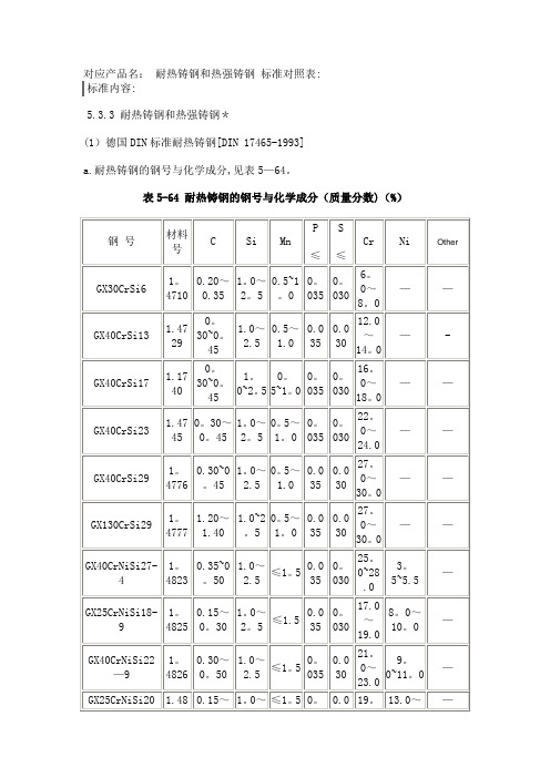
耐热铸钢和热强铸钢标准对照表:
标准内容:
5.3.3 耐热铸钢和热强铸钢*
(1)德国DIN标准耐热铸钢[DIN 17465-1993]
a.耐热铸钢的钢号与化学成分,见表5—64。
表5-64 耐热铸钢的钢号与化学成分(质量分数)(%)
b。
耐热铸钢的室温力学性能,见表5-56.
表5—56 耐热铸钢的室温力学性能
c。
耐热铸钢的高温力学性能,见表5—66。
表5-66 耐热铸钢的高温力学性能
(2)德国DIN标准铁素体热强铸钢[DIN 17245—1987]
a。
铁素体热强铸钢的钢号与化学成分,见表5—67.
表5-67 铁素体热强铸钢的钢号与化学成分(质量分数)(%)
b.铁素体热强铸钢的力学性能,见表5-68。
表5-68 铁素体热强铸钢的力学性能。
Met One Instruments BX-301 中文名字说明书

BX-301M ID R ANGE M EMBRANEI NSTRUCTIONSMet One Instruments, Inc.1600 NW Washington Blvd.Grants Pass, Oregon 97526Telephone 541-471-7111Facsimile 541-471-71161 About the BX-301 Mid-Range MembraneThe BX-301 is a special purpose mid-range membrane foil assembly which may be used to verify the linearity of the BAM-1020 mass calculation system. The mass calculation of the BAM-1020 is inherently linear in nature, and therefore it is unnecessary to audit a mid range point in the vast majority of applications. The BX-301 is provided only as a convenience to certain customers who may be required to perform the check by local regulations.The BAM-1020 unit performs a span membrane check automatically every hour using it’s built-in membrane with a mass of approximately 0.800 mg/cm2. The BX-301 allows the user to periodically perform an additional span check at about 0.500 mg/cm2.The BX-301 membrane is a fragile assembly, and must be handled very carefully. Any puncture or damage to the foil surface will render the part useless. Any dirt or contamination on the foil surface will be measured as mass, and will also invalidate the measurement. This assembly must be protected and stored in a safe location away from heat and direct sunlight.2 Mid Range Span Check ProcedureNote: The BAM-1020 unit must be powered on and warmed up for at least one hour before performing the test. The pump does not need to be running during warm-up.1. Remove the ten case cover screws and washers from the BAM-1020. You will needto access the inside of the unit later to complete the test.2. Verify the factory determined ABS value of the BAM-1020 unit. This can be found inthe SETUP > CALIBRATE menu or on the calibration certificate for the unit. This is the expected mass of the span membrane foil in the unit, and will be about 0.800mg/cm2.3. Enter the TEST > CALIBRATE menu on the user interface. This is the screen thatwill be used for the membrane tests. See Section 7.13 of the BAM-1020 manual.The CALIBRATE Test Screen4. Press the START soft key to start a membrane measurement with the existing foil.The test will take about eight minutes to complete. The unit will then display themeasured value of the span membrane foil as the CAL MASS M value. Comparethis value with the ABS (expected) value and record the results. These shouldtypically match within a few micrograms. Note: If these values disagree by 5% ormore, then there is something wrong with the unit such as a dirty membrane or an incorrect ABS value. Do not proceed with the test if the BAM-1020 is not reading its own membrane correctly.5. Remove the BAM case cover. Locate the membrane assembly on the inside of theunit, and the brass raceway in which the membrane assembly slides forwards and backwards. Remove the small dust cover (two small screws and washers). Set the parts aside.MembraneMotorDust CoverMembraneAssemblyMembraneControl ArmThe Membrane Assembly Inside the BAM-10206. Carefully remove the existing membrane from the unit: Pull back the control armagainst it’s spring pressure until you can slide the membrane from the back of the assembly. There should be an expected mass value printed on the back of the mid-range membrane. Record this value. Insert the mid-range membrane foil exactly as the other membrane was installed. Note: Make sure the pin of the membrane is in the slot of the control arm, or the test will not work. Swapping membranes is a very simple matter once you know what you are doing.7. Press the START soft-key to start the test with the mid-range membrane in place.When the unit has calculated and displayed the new CAL MASS M value, record it and start the test over. Perform the test two more times and take an average of the three measured values. This average must be within 5% of the expected valueprinted on the membrane, and will typically be within a few micrograms. Record the results.8. Remove the mid-range membrane and replace the original part. Reinstall the smalldust cover and the main case cover of the BAM-1020.BAM-1020 Membrane Foil Mid-Range Linearity CheckTest Results Record:Test Performed By:Test Date:BAM-1020 Serial Number:Expected ABS Value:mg/cm2Measured Mass of Existing Foil:mg/cm2Difference:mg/cm2Difference %:%Expected Mass of Mid-Range Foil:mg/cm2Measured Mid-Range Mass, Test 1:mg/cm2Measured Mid-Range Mass, Test 2:mg/cm2Measured Mid-Range Mass, Test 3:mg/cm2Average Mid-Range Mass:mg/cm2Difference from Expected Value:mg/cm2Difference %:%。
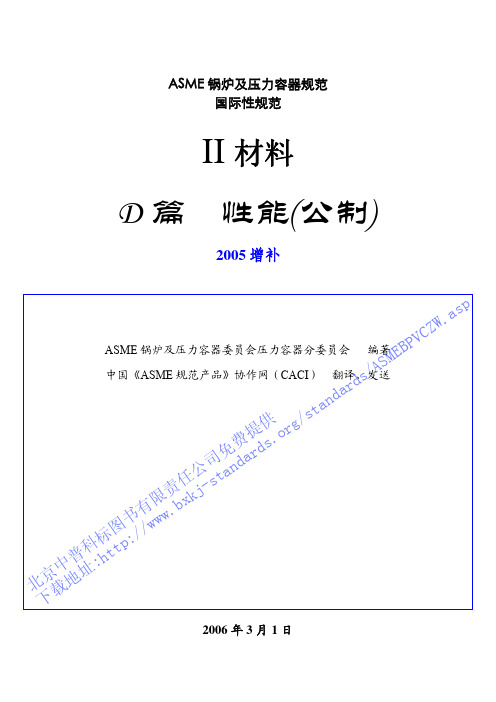
4中文版ASME规范+第Ⅱ卷+D篇+材料性能+2005增补
21| …(17 个)
A05
新增加:
A05 22 | 27Ni-22Cr-7Mo-Mn-Cu-N 锻件 SA-182 …
S31277 … … 45 …
22 | 772 359 NP NP 427 NP NFN-26 …
A05
A05 22 | 221 221 219 … 198 184 177 175 175 175
30 | 772 359 NP NP 427 NP NFN-26 …
A05
A05 30 | 221 221 219 … 198 184 177 175 175 175
175 173 172 172 …
30 | …(17 个)
A05
4
ASME BPVC 2005 增补
第 II 卷 D 篇
性能(公制)
节号 节号 节号 节号
ASMEB 2-5
表 1A 第 19 行
ards/ 14-17 表 1A(续) 第 16 行
费提供/stand 62-65 表1A(续) 第 21 行
书有w限ww责.b任xk公j-司st免andard 62-65 表1A(续) 第 22 行
北下京载中地普址科:标ht图tp:// 62-65 表1A(续) 第 23 行
A05 27 | 188 188 187 … 180 173 167 162 160 158
157 155 154 154 …
27 | …(17 个)
A05
新增加:
A05 28 | 27Ni-22Cr-7Mo-Mn-Cu-N 焊接管子 SA-249 …
S31277 … … 45 …
28 | 772 359 NP NP 427 NP NFN-26 …
槽钢C型钢工字钢H型钢的区别和重量表
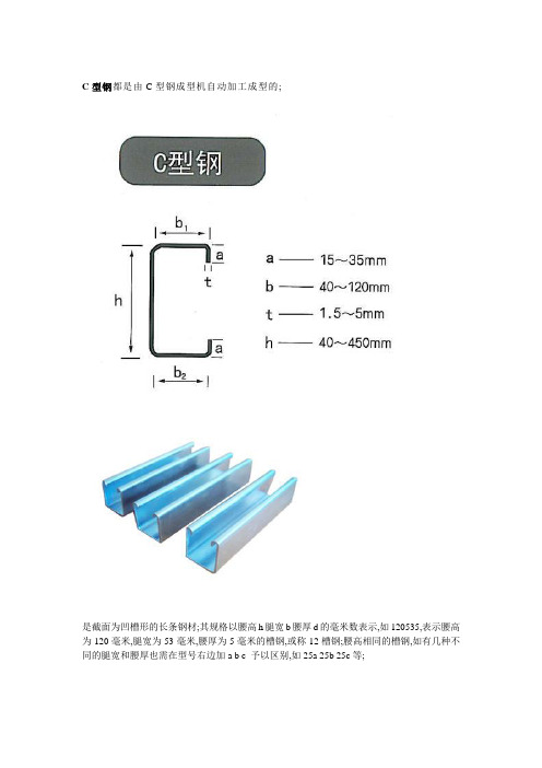
C型钢都是由C型钢成型机自动加工成型的;是截面为凹槽形的长条钢材;其规格以腰高h腿宽b腰厚d的毫米数表示,如120535,表示腰高为120毫米,腿宽为53毫米,腰厚为5毫米的槽钢,或称12槽钢;腰高相同的槽钢,如有几种不同的腿宽和腰厚也需在型号右边加a b c 予以区别,如25a 25b 25c等;工字钢也称钢梁英文名称I Beam,是截面为工字形的长条;工字钢分普通工字钢和轻型工字钢,H形钢三种;H-型钢是由工字型钢优化发展而成的一种断面力学性能更为优良的经济型断面钢材,尤其断面与英文字母“H”相同而得名;H型钢分为宽翼缘H型钢HW中翼缘H型钢HM窄翼缘H型钢HN薄壁H型钢HTH型钢桩HU工字钢 HW HM HN H型钢的区别工字钢翼缘是变截面靠腹板部厚,外部薄; H型钢的翼缘是等截面HW HM HN H是H型钢的通称,H型钢是焊制; HW HM HN是热轧HW 是H型钢高度和翼缘宽度基本相等;主要用于钢筋砼框架结构柱中钢芯柱,也称劲性钢柱;在钢结构中主要用于柱HM 是H型钢高度和翼缘宽度比例大致为1.33~~1.75 主要在钢结构中:用做钢框架柱在承受动力荷载的框架结构中用做框架梁;例如:设备平台HN 是H型钢高度和翼缘宽度比例大于等于2,主要用于梁;工字钢的用用途相当于HN型钢;1、工字型钢不论是普通型还是轻型的,由于截面尺寸均相对较高、较窄,故对截面两个主袖的惯性矩相差较大,因此,一般仅能直接用于在其腹板平面内受弯的构件或将其组成格构式受力构件;对轴心受压构件或在垂直于腹板平面还有弯曲的构件均不宜采用,这就使其在应用范围上有着很大的局限;2、 h型钢属于高效经济裁面型材其它还有冷弯薄壁型钢、压型钢板等,由于截面形状合理,它们能使钢材更高地发挥效能,提高承裁能力;不同于普通工字型的是h型钢的翼缘进行了加宽,且内、外表面通常是平行的,这样可便于用高强度螺桂和其他构件连接;其尺寸构成合理系列,型号齐全,便于设计选用;3、h型钢的翼缘都是等厚度的,有轧制截面,也有由3块板焊接组成的组合截面;工字钢都是轧制截面,由于生产工艺差,翼缘内边有1:10坡度;H型钢的轧制不同于普通工字钢仅用一套水平轧辊,由于其翼缘较宽且无斜度或斜度很小,故须增设一组立式轧辊同时进行辊轧,因此,其轧制工艺和设备都比普通轧机复杂;国内可生产的最大轧制h型钢高度为800mm,超过了只能是焊接组合截面;我国热轧H型钢国标GB/T11263-1998将h型钢分为窄翼缘、宽翼缘和钢桩三类,其代号分别为hz、hk和hu;窄翼缘h型钢适用于梁或压弯构件,而宽翼缘h 型钢和h型钢桩则适用于轴心受压构件或压弯构件;工字钢与H型钢相比,等重量前提下,w、 ix、 iy都不如h型钢五、工字钢单位重量表热轧普通工字钢每米重量表热轧轻型工字钢每米重量表六、槽钢单位重量表热轧普通槽钢每米重量表热轧轻型槽钢每米重量表七、轨道材料重量表钢轨每米重量表鱼尾板每块重量表①方钢——热轧方钢、冷拉方钢;②圆钢——热轧圆钢、锻制圆钢、冷拉圆钢③线材;④扁钢;⑤弹簧扁钢;⑥角钢——等边角钢、不等边角钢;⑦三角钢⑧六角钢;⑨弓形钢;⑩椭圆钢2 .复杂断面型钢①工字钢——普通工字钢、轻型工字钢②槽钢——热轧槽钢普通槽钢、轻型槽钢、弯曲槽钢③ H 型钢又称宽腿工字钢④钢轨——重轨、轻轨、起重机钢轨、其他专用钢轨⑤窗框钢⑥钢板桩⑦弯曲型钢——冷弯型钢、热弯型钢工字钢工字钢的外形,长度,重量,牌号,化学成分,力学性能,工艺性能和表面质量外形热轧工字钢尺寸,外形,重量及允许偏差热轧普通工字钢 YB T56-1987弯曲度:工字钢每米弯曲度不大于 2MM ,总弯曲度不大于总长度的 0.2%扭转:工字钢不得有明显的扭转弯曲度:工字钢高度小于或等于 400MM 时,每米弯曲度不得大于1.5MM ,总弯曲度不得大于总长度的 0.15% ;高度大于 400MM 时,每米弯曲度不得大于。
jotun 高固含氟碳面漆F10 (6G6) 技术规格表说明书
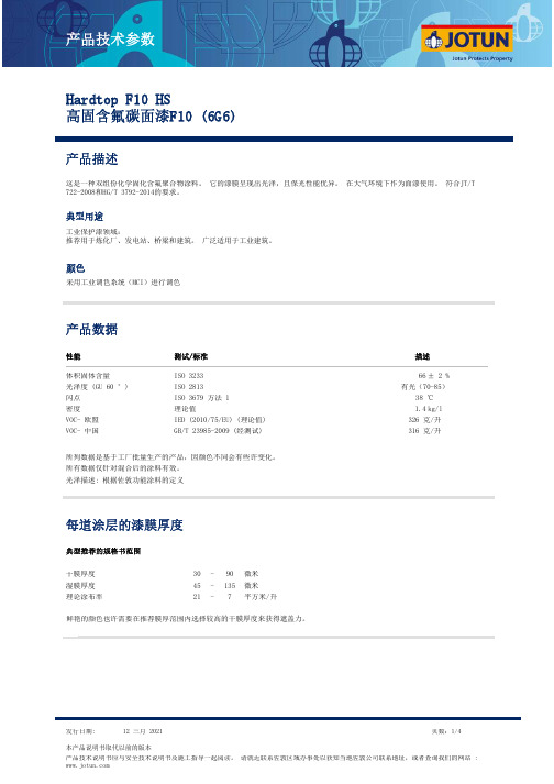
高固含氟碳面漆F10 (6G6)这是一种双组份化学固化含氟聚合物涂料。
它的漆膜呈现出光泽,且保光性能优异。
在大气环境下作为面漆使用。
符合JT/T 722-2008和HG/T 3792-2014的要求。
颜色采用工业调色系统(MCI)进行调色典型用途工业保护漆领域:推荐用于炼化厂、发电站、桥梁和建筑。
广泛适用于工业建筑。
性能测试/标准描述光泽度 (GU 60 °)ISO 2813VOC- 欧盟IED (2010/75/EU) (理论值)闪点ISO 3679 方法 138 ℃有光(70-85)326 克/升密度 1.4kg/l 光泽描述: 根据佐敦功能涂料的定义理论值所有数据仅针对混合后的涂料有效。
VOC- 中国GB/T 23985-2009 (经测试)316 克/升湿膜厚度理论涂布率304521901357微米微米平方米/升---该产品可用以下方式施工喷涂:使用有气喷涂或无气喷涂。
刷涂:推荐用于预涂和小面积涂装。
注意要达到特定的干膜厚度。
10份份1高固含氟碳面漆F10 / F15 组份B稀释剂:佐敦10号稀释剂喷嘴孔径 (inch/1000):喷嘴压力 (最小):13-15100 bar / 1450 psi可踩踏干燥32 小时16 小时8 小时 4 小时15 天10 天 5 天 2 天5 °C10 ℃23 °C40 °C干燥/固化至可使用干燥后复涂,最短间隔32 小时16 小时8 小时 4 小时23 °C 温度干燥,大气环境中℃120连续的峰值140℃以上温度下,保护性能不受影响。
但是美观性可能会有影响。
下道涂层:环氧、改性环氧、 聚氨酯含氟聚合物容器大小(升)高固含氟碳面漆F10 / F15 组份B1.8203体积(升)4848高固含氟碳面漆F10 组份A高固含氟碳面漆F10 / F15 组份B个月个月本产品仅供专业人员使用。
施工人员和工人需要培训、有经验、有能力和设备根据佐敦的技术文件来正确的混合/搅拌和施涂油漆。
WB DOE--Example

17.80
19.29 17.75 18.84 14.31 19.66
0.82
1.07 1.04 1.27 1.01 1.07
3.96
3.53 3.12 2.84 2.09 3.63
4.39
4.62 3.63 4.17 4.23 4.28
4.80
4.98 4.68 4.84 5.04 4.78
0.31
HTS (336hrs at 175°C)
Next Step
1.3mm OH@75um WT in 65nm wafer structure
WB Parameter DOE (1st bond in 1.3mm OH@75um WT) - Test response : BST, BPT, Ball Size, Ball thickness, visual - Sample Size : 16 legs
. Optimum parameter Bump USG Bump Time Bump Force
windows are as followings ; : 78mA to 90mA : 20ms : 8gf to 11gf
Optimum parameter range
8
Data Analysis
B/Diagram 3
DOE Procedure
Bump size of reverse bonding for pad to pad bonding (after stitch bonding)
WB Parameter DOE (Bump size of pad to pad bonding) - Test response : BST, Wire peel test, Bump Size, visual - Sample Size : 16 legs
槽钢、C型钢、工字钢、H型钢的区别和重量表

C型钢都是由C型钢成型机自动加工成型的。
槽钢是截面为凹槽形的长条钢材。
其规格以腰高(h)*腿宽(b)*腰厚(d)的毫米数表示,如120*53*5,表示腰高为120毫米,腿宽为53毫米,腰厚为5毫米的槽钢,或称12#槽钢。
腰高相同的槽钢,如有几种不同的腿宽和腰厚也需在型号右边加a b c 予以区别,如25a# 25b# 25c#等。
工字钢也称钢梁(英文名称I Beam),是截面为工字形的长条钢材。
工字钢分普通工字钢和轻型工字钢,H形钢三种。
H-型钢是由工字型钢优化发展而成的一种断面力学性能更为优良的经济型断面钢材,尤其断面与英文字母“H”相同而得名。
H型钢分为宽翼缘H型钢(HW)中翼缘H型钢(HM)窄翼缘H型钢(HN)薄壁H型钢(HT)H型钢桩(HU)工字钢 HW HM HN H型钢的区别工字钢翼缘是变截面靠腹板部厚,外部薄; H型钢的翼缘是等截面HW HM HN H是H型钢的通称,H型钢是焊制; HW HM HN是热轧HW 是H型钢高度和翼缘宽度基本相等;主要用于钢筋砼框架结构柱中钢芯柱,也称劲性钢柱;在钢结构中主要用于柱HM 是H型钢高度和翼缘宽度比例大致为1.33~~1.75 主要在钢结构中:用做钢框架柱在承受动力荷载的框架结构中用做框架梁;例如:设备平台HN 是H型钢高度和翼缘宽度比例大于等于2,主要用于梁;工字钢的用用途相当于HN型钢;1、工字型钢不论是普通型还是轻型的,由于截面尺寸均相对较高、较窄,故对截面两个主袖的惯性矩相差较大,因此,一般仅能直接用于在其腹板平面内受弯的构件或将其组成格构式受力构件。
对轴心受压构件或在垂直于腹板平面还有弯曲的构件均不宜采用,这就使其在应用范围上有着很大的局限。
2、 h型钢属于高效经济裁面型材(其它还有冷弯薄壁型钢、压型钢板等),由于截面形状合理,它们能使钢材更高地发挥效能,提高承裁能力。
不同于普通工字型的是h型钢的翼缘进行了加宽,且内、外表面通常是平行的,这样可便于用高强度螺桂和其他构件连接。
ASTM E446-2010
Designation:E446–10Standard Reference Radiographs forSteel Castings Up to2in.(50.8mm)in Thickness1This standard is issued under thefixed designation E446;the number immediately following the designation indicates the year of original adoption or,in the case of revision,the year of last revision.A number in parentheses indicates the year of last reapproval.A superscript epsilon(´)indicates an editorial change since the last revision or reapproval.This standard has been approved for use by agencies of the Department of Defense.1.Scope1.1These reference radiographs2illustrate various catego-ries,types,and severity levels of discontinuities occurring in steel castings that have section thicknesses up to2in.(50.8 mm)(see Note2).The reference radiographfilms are an adjunct to this standard and must be purchased separately from ASTM International,if needed(see2.2).Categories and severity levels for each discontinuity type represented by these reference radiographs are described in1.2.N OTE1—The basis of application for these reference radiographs requires a prior purchaser supplier agreement of radiographic examination attributes and classification criterion as described in Sections4,6,and7 of this standard.N OTE2—Reference radiographs previously used for this thickness range carried the designation E71,but included a now rarely used gamma source,that is,radium.The current document is also updated by inclusion of several recognized shrinkage or C categories and by elimination of the crack and hot tear categories except for one example of each of these discontinuity types.Reference radiographs for thicker sections may be found in Reference Radiograph standards E186and E280.Reference Radiograph standards E446and E186provide some overlap of severity levels for similar discontinuity categories within the same energy level range(see4.2,5.1,and6.3).1.2These reference radiographs consist of three separate volumes(see Note3)as follows:(I)medium voltage(nominal 250-kV)X rays.(II)1-MV X rays and Iridium-192radiation, and(III)2-MV to4-MV X rays and cobalt-60radiation.Unless otherwise specified in a purchaser supplier agreement(see1.1), each volume is for comparison only with production radio-graphs produced with radiation energy levels within the thick-ness range covered by this standard.Each volume consists of six categories of graded discontinuities of increasing severity level and four categories of ungraded discontinuities.Refer-ence radiographs containing ungraded discontinuities are pro-vided as a guide for recognition of a specific casting disconti-nuity type where severity levels are not needed.Following is a list of discontinuity categories,types and severity levels for the adjunct reference radiographs of this standard:1.2.1Category A—Gas porosity;severity levels1through 5.1.2.2Category B—Sand and slag inclusions;severity levels 1through5.1.2.3Category C—Shrinkage;4types:1.2.3.1Ca—Severity levels1through5.1.2.3.2Cb—Severity levels1through5.1.2.3.3Cc—Severity levels1through5.1.2.3.4Cd—combinations of linear,feathery and sponge shrinkage—Severity levels1through5.1.2.4Category D—Crack;1illustration.1.2.5Category E—Hot tear;1illustration.1.2.6Category F—Insert;1illustration.1.2.7Category G—Mottling;1illustration.N OTE3—The reference radiographs consist of the following:Volume I:Medium Voltage(nominal250kVp)X-Ray Reference Radiographs—set of34illustrations(nominal5by7in.)in a15by17-in. ring binder.Volume II:1-MV X Rays and Iridium-192Reference Radiographs—Set of34illustrations(nominal5by7in.)in a15by17-in.ring binder.Volume III:2-MV to4-MV X Rays and Cobalt-60Reference Radiographs—Set of34illustrations(nominal5by7in.)in a15by17-in. ring binder.N OTE4—Although Category G–Mottling is listed for all three volumes, the appearance of mottling is dependent on the level of radiation energy. Mottling appears reasonably prominent in V olume I;however,because of the higher radiation energy levels mottling may not be apparent in V olume II nor V olume III.1.3The values stated in inch-pound units are to be regarded as the standard.SI values are shown for information only. 1.4This standard does not purport to address all of the safety concerns,if any,associated with its use.It is the responsibility of the user of this standard to establish appro-priate safety and health practices and determine the applica-bility of regulatory limitations prior to use.1These reference radiographs are under the jurisdiction of ASTM CommitteeE07on Nondestructive Testing and are the direct responsibility of SubcommitteeE07.02on Reference Radiological Images.Current edition approved Jan.1,2010.Published February2010.Originallyapproved st previous edition approved in2004as E446–98(2004)´1.DOI:10.1520/E0446-10.2For ASME Boiler and Pressure Vessel Code applications see related ReferenceRadiographs SE-446in Section V of that Code.Copyright©ASTM International,100Barr Harbor Drive,PO Box C700,West Conshohocken,PA19428-2959,United States. --``,`,``,,`,``,,,`,``,``,,`,,``-`-`,,`,,`,`,,`---2.Referenced Documents 2.1ASTM Standards:3E94Guide for Radiographic ExaminationE186Reference Radiographs for Heavy-Walled (2to 412-in.[51to 114-mm])Steel CastingsE242Reference Radiographs for Appearances of Radio-graphic Images as Certain Parameters Are ChangedE280Reference Radiographs for Heavy-Walled (412to 12-in.[114to 305-mm])Steel CastingsE1316Terminology for Nondestructive Examinations 2.2ASTM Adjuncts:4Reference Radiographs for Steel Castings Up to 2in.(50.8mm)in Thickness:V olume I,Medium V oltage (Nominal 250kVp)X-Rays 5V olume II,1-MV X-Rays and Iridium-1926V olume III,2-MV to 4-MV X-Rays and Cobalt-6073.Terminology3.1Definitions —For definitions of terms relating to radio-graphic examination,see Terminology E1316.3.2Definitions of Terms Specific to This Standard:3.2.1production radiograph —a radiograph under review for compliance with this standard.3.2.2discontinuity type —a specific discontinuity character-ized by its cause and appearance.For example:linear shrink-age is a specific discontinuity type.3.2.3discontinuity category —a nomenclature system used for grouping discontinuity types.For example:linear shrinkage is assigned category “Ca”where “C”represents the general shrinkage category and “a”represents the specific linear shrinkage discontinuity type.3.2.4discontinuity severity level —a relative rank in terms of “quantity,size and distribution”of a collection of disconti-nuities where “1”is the least and “5”is the greatest “quantity,size and distribution”present on the reference radiograph.Example:a severity level of “1”is more restrictive (requires a higher level of workmanship fabrication quality)than a sever-ity level of “2”.3.2.5discontinuity class —an assigned workmanship fabri-cation quality rating characterized by a discontinuity type,category and severity level.For example:“Ca 2”is a discon-tinuity class comprised of linear shrinkage with a severity level of “2”.3.2.6classification specification —a set of user defined ac-ceptance criterion that prescribes the radiographic workman-ship discontinuity class requirements for a specified user casting service application (see Sections 6and 7).3.2.7graded illustration —a category of discontinuity that is assigned a severity level.3.2.8ungraded illustration —a category of discontinuity without an assigned severity level.3.2.9prorating —assignment of quantity,size and distribu-tion on a production radiograph in proportion to a similar size area of a reference radiograph.For example:a production radiograph covers an area that is smaller than the unit area of a reference radiograph and the extent of discontinuity on the applicable reference radiograph is reduced proportionately.4.Significance and Use4.1Graded reference radiographs are intended to provide a guide enabling recognition of specific casting discontinuity types and relative severity levels that may be encountered during typical fabrication processes.Reference radiographs containing ungraded discontinuities are provided as a guide for recognition of a specific casting discontinuity type where severity levels are not needed.These reference radiographs are intended as a basis from which manufacturers and purchasers may,by mutual agreement,select particular discontinuity classes to serve as standards representing minimum levels of acceptability (see Sections 6and 7).4.2Reference radiographs represented by this standard may be used,as agreed upon in a purchaser supplier agreement,for energy levels,thicknesses or both outside the range of this standard when determined applicable for the casting service application.Severity levels of similar discontinuity categories and energy level range of E186reference radiographs may alternatively be used,as determined appropriate for the casting service application,if so agreed upon in the purchaser supplier agreement (see Note 2and5.1).4.3Procedures for evaluation of production radiographs using applicable reference radiographs of this standard are prescribed in Section 8;however,there may be manufacturing-purchaser issues involving specific casting service applications where it may be appropriate to modify or alter such require-ments.Where such modifications may be appropriate for the casting application,all such changes shall be specifically called-out in the purchaser supplier agreement or contractual document.Section 9addresses purchaser supplier requisites for where weld repairs may be required.5.Method of Preparation5.1The original radiographs used to prepare the adjunct reference radiographs were produced on ASTM Class I or II film systems by the respective use of 250-kV X-ray,Iridium-192and Cobalt-60sources of radiation.The original radio-graphs were made with penetrameter sensitivity as determined by ASTM penetrameters (see Guide E94)of 2-2T.The adjunct reference radiographs are reproductions prepared to an optical density of 2.00to 2.25and have substantially retained the contrast of the original radiographs.In preparing these refer-ence radiographs,the objective was to obtain progressively graduated severity levels for each graded discontinuity cat-egory of this standard.Additionally,some overlap of severity levels may occur for discontinuity categories of this standard and similar discontinuity categories of E186reference radio-graphs within the same energy level range.For example,aggregate gas porosity severity level 5of this standard exceeds aggregate gas porosity severity level 1of Reference Radio-graph E186(see6.3).3For referenced ASTM standards,visit the ASTM website,,or contact ASTM Customer Service at service@.For Annual Book of ASTM Standards volume information,refer to the standard’s Document Summary page on the ASTM website.4Available from ASTM Headquarters.5Order RRE044601.6Order RRE044602.7Order RRE044603.--``,`,``,,`,``,,,`,``,``,,`,,``-`-`,,`,,`,`,,`---5.2Film Deterioration—Radiographicfilms are subject to wear and tear from handling and use.The extent to which the image deteriorates over time is a function of storage condi-tions,care in handling and amount of use.Reference radio-graphfilms are no exception and may exhibit a loss in image quality over time.The radiographs should therefore be peri-odically examined for signs of wear and tear,including scratches,abrasions,stains,and so forth.Any reference radio-graphs which show signs of excessive wear and tear which could influence the interpretation and use of the radiographs should be replaced.6.Determination of Radiographic Classification6.1For purposes of evaluation of castings,a determination must be made of the radiographic discontinuity classifications to be assigned to individual castings or specific areas of castings.The determination of the applicable radiographic discontinuity classification shall be based on an evaluation of the casting applications,design,and service requirements.In these evaluations,consideration shall be given to such factors as pressure,temperature,section thickness,applicable design safety factor(preferably based on stress analysis),vibration, shock,resistance to corrosion,involvement of penetrating radiations or radiation products,and involvement of dangerous gases or liquids.6.2For each individual casting or specific area of a casting to be radiographed,the discontinuity class must be clearly specified.For example,severity level2might be specified for linear shrinkage,Category Ca,and severity level3for gas porosity,Category A,since the latter are generally much less deleterious to tensile properties(see Section7).6.3When determining discontinuity severity levels for in-dividual castings spanning multiple thickness ranges outside the range of this standard,consideration should be given to the potential for overlaping severity levels as described in4.2and5.1.6.4Production radiographs which are compared to refer-ence radiographs should have an optical density in the area of interest in accordance with Guide E94and a specified mini-mum radiographic sensitivity(quality level)of2%(2-2T). Other radiographic quality levels or optical densities may be designated,but then a corresponding change in severity level for each discontinuity category should be anticipated and hence specified.7.Classification Specifications7.1The applicable radiographic discontinuity classification should be designated by the contracting agency in formal specifications or on drawings and in specific contracts or orders.The specifications,drawings,contracts,or order should also designate the sampling plan for the castings to be radiographed and the extent of radiographic coverage,radio-graphic practice to be followed(Guide E94),image quality desired(Note5)as well as the severity of the acceptable discontinuity for the graded categories.N OTE5—For description of radiographic sensitivity or quality levels,see Guide E94and Reference Radiographs E242.8.Evaluation Procedure8.1Compare the production radiographs of the casting submitted for evaluation with the reference radiographs ex-posed at an equivalent energy range within the thickness range of this standard(unless otherwise specified—see Section4).8.2When the severity level of discontinuities in the produc-tion radiograph being evaluated is equal to or less than the severity level in the specified reference radiograph,that part of the casting represented by the production radiograph shall be acceptable.If the production radiograph shows discontinuities of greater severity than the reference radiograph,that part of the casting shall be rejected.8.3A unit area on the production radiograph shall be evaluated to a unit area of like size on the reference radiograph. Any unit evaluation area that shares a discontinuity with an adjacent unit evaluation area shall meet the minimum unit area acceptability requirements within the combined unit area. When the unit area of interest of a production radiograph is less than the unit area of the applicable reference radiograph,such unit area of the production radiograph shall be prorated to the reference radiographic area.8.4When two or more categories of discontinuity are present in the same production radiograph,the predominating discontinuites,if unacceptable,shall govern without regard to the other categories of discontinuity and the casting rejected.8.5When two or more categories of discontinuity are present to an extent equal to the maximum permissible level as shown in the applicable standards for each category,then that part of the casting shall be judged unacceptable.When two or more categories of discontinuity are present in the same radiograph to an extent less than the maximum permissable level,as shown in the applicable standards for each category, the severity shall be evaluated by the overall aggregate condition.The aggregate condition is defined as the balance of quantity,size and distribution of the collection of discontinui-ties and shall not exceed the aggregate condition of the applicable reference radiograph.8.6Reference radiographs are provided showing a variety of shrinkage discontinuity types.Production radiographs show-ing shrinkage shall be judged by the most representative reference radiograph.8.7This standard does not specify limiting criteria for a single size of discontinuity,maximum number of discontinui-ties per unit area evaluated,specific dimensional spacing and/or alignment criterion between individual discontinuities or any other undefined discontinuitiy patterns.Unless other-wise specified by a purchaser supplier agreement(see Section 4),these discontinuity conditions on production radiographs shall be evaluated as aggregate conditions as defined in8.5.8.8In general,there is no limit as to the extent of acceptable discontinuities in a casting,provided that no unit evaluation area throughout the casting contains discontinuities that exceed the severity of discontinuities in the applicable referenceradiographs. --``,`,``,,`,``,,,`,``,``,,`,,``-`-`,,`,,`,`,,`---8.9Reference radiographs in this standard do not illustrate elongated or“worm hole”type of gas discontinuities.When this condition occurs in a production radiograph,it shall be evaluated by comparison with the most representative refer-ence radiograph.8.9.1When the exposing radiation source has been placed perpendicular to the length of the gas hole,evaluate the production radiograph with a shrinkage reference radiograph.8.9.2When the exposing radiation source has been placed diametrically or“into”the diameter of the gas hole,evaluate the production radiograph with a gas reference radiograph.8.10A diffraction mottling pattern can occur onfilms of parts and sections where the grain size is large enough to be an appreciable fraction of the material thickness(Note6).If diffraction mottling is suspected,there are a number of ways to demonstrate its presence.The diffraction mottling pattern shown in these cases is dependent principally upon the crystal geometry and the orientation of the crystals to the incident radiation.Therefore,for a given specimen,any change in this orientation will affect the diffraction pattern dramatically.This can be accomplished by a slight,1to5°tilt of the part,with respect to the radiation beam or simply by shifting the center line of the radiation beam to a slightly different location from thefirst exposure.Indications from any porosity,shrinkage,or other discontinuity will move only slightly,while any mottling patterns present will change dramatically.If it is necessary or desirable to eliminate the mottling,the kV may be raised to reduce the amount of diffraction radiation.However,caution should be used so that the kV is not raised to the point that sensitivity is reduced excessively.If diffraction mottling is demonstrated to be present on a radiograph,this condition shall not be considered as prejudicial in evaluating the radiograph. N OTE6—Mottling is often associated with thin sections of austenitic steels,and copper base alloys such as copper nickel,tin bronzes,and nickel copper.8.11Hot tears and cracks exhibited on production radio-graphs may at times resemble linear type shrinkage.When doubt exists whether such indications are cracks or tears,or are linear shrinkage,all surfaces in the area of interest shall be ground and magnetic particle or liquid penetrant inspected as applicable.The extent and depth of grinding may require engineering judgment.If the indication does not appear on the surface,that indication shall be considered shrinkage.8.12The radiographic density of discontinuities in compari-son with background density is a variable dependent on technical factors.It shall not be used as a criterion for acceptance or rejection in comparison with reference radio-graphs.9.Weld Repair of Castings9.1When radiographic quality castings are repaired by welding,the reference radiographs to be used in the evaluation of the repaired sections must be specifically agreed upon between purchaser and supplier.9.2When casting discontinuities are removed for repairs, only the extent of discontinuity required to meet applicable reference standards need be removed.10.Keywords10.1discontinuity classification criterion;gamma ray;ref-erence radiographs;steel castings;x-rayASTM International takes no position respecting the validity of any patent rights asserted in connection with any item mentioned in this ers of this standard are expressly advised that determination of the validity of any such patent rights,and the risk of infringement of such rights,are entirely their own responsibility.This standard is subject to revision at any time by the responsible technical committee and must be reviewed everyfive years and if not revised,either reapproved or withdrawn.Your comments are invited either for revision of this standard or for additional standards and should be addressed to ASTM International Headquarters.Your comments will receive careful consideration at a meeting of the responsible technical committee,which you may attend.If you feel that your comments have not received a fair hearing you should make your views known to the ASTM Committee on Standards,at the address shown below.This standard is copyrighted by ASTM International,100Barr Harbor Drive,PO Box C700,West Conshohocken,PA19428-2959, United States.Individual reprints(single or multiple copies)of this standard may be obtained by contacting ASTM at the above address or at610-832-9585(phone),610-832-9555(fax),or service@(e-mail);or through the ASTM website ().Permission rights to photocopy the standard may also be secured from the ASTM website(/COPYRIGHT/).--` ` , ` , ` ` , , ` , ` ` , , , ` , ` ` , ` ` , , ` , , ` ` -` -` , , ` , , ` , ` , , ` ---。
Carter Ground Fueling Model 64031 3英寸双性接口应用说明说明书
Model 640313" Unisex CouplingA pplicable additional manuals :NONESM 64031May 2007Maintenance & Repair ManualAerospace GroupConveyance Systems DivisionCarter ® Brand Ground Fueling EquipmentTABLE OF CONTENTSPAGE (3)1.0 INTRODUCTIONDESCRIPTION (3)2.0 EQUIPMENT3.0 TABLE OF OPTIONS AND ORDERING INFORMATION (3)4.0 DISASSEMBLY (3)5.0 INSPECTION (4)6.0 REASSEMBLY (4)7.0 TEST (5)8.0 ILLUSTRATED PARTS CATALOG (6)MAINTENANCE, OVERHAUL & TEST INSTRUCTIONSCARTER PART NUMBER 64031 UNISEX COUPLING 1.0 INTRODUCTIONThis manual furnishes detailed instructions covering the maintenance and overhaul of Carter Ground Fueling Model Number 64031, 3" Unisex Couplings and the various options listed in Section 3.0.2.0 EQUIPMENT DESCRIPTIONCarter Model 64031 Valved Unisex Coupling is a 3 inch hose coupling that is universally connectable to other 64031 Valved Unisex Couplings. The units are qualified in accordance with A-A 59377, Class A which supercedes MIL-C-53071. Section 3.0 details the various options available. Other configurations of Carter units that are available and to which the 64031 will mate are listed in Section 3.0. The basic valved coupling would be procured under the part number 64031 with various options that determine the desired inlet or hose mounting configuration. The exploded views in the figures at the end of the manual include the various options available. Item numbers referenced in Sections 4 through 7 refer to the parts list in Table 1.3.0 TABLE OF OPTIONS AND ORDERING INFORMATIONThe 64031 is available with various inlet or hose mounting configurations as described in the tables below. The units are available in two colors to meet the customers requirements, tan (standard) and green (option V).DESCRIPTION OPTION LETTER DESCRIPTION OPTION LETTERC Adds 100 Mesh Screen N Adds 1-1/2" Male NPT inletD Adds 3" Hose Barb Inlet P Adds 4" Male Camlock InletE Adds 4" Hose Barb Inlet Q Adds Dust Cap/Plugs, Camlock TypeF Adds 2" Male Camlock Inlet R Adds 3" Female NPT InletG Adds 2" Female Camlock Inlet S Adds 3" Male NPT InletH Adds D-1/D-2 Inlet Flange T Adds 3" MS33786-48 Flanged InletJ Adds 2" Male NPT Inlet U Adds 3" Vitaulic Grooved End Inlet K Adds 3" Female Camlock Inlet V Changes exterior color to greenL Adds 2” Hose Barb Inlet W Adds 4" Male BSPP InletM Adds 4" Female Camlock Inlet Z CRES Interface Locking Lugs Note: One of the above options letters must be included with the basic part number 64031 to receivea completed unit.Example: 64031D - 3" Unisex Coupling with 3" Hose Barb Inlet Fitting.64031KQ – 3” Unisex Coupling with 3” Female Camlock Inlet and Dust Plug.4.0 DISASSEMBLY4.1 Remove Screw (1) using a torque wrench,checking the running torque. If the runningtorque is less than 9.5 in lbs (0.11 m kg),discard the Screw (1). Note: Screw (1) isself-locking and is designed to be reused upto 15 times before replacement is necessary. If a torque wrench is not used to remove it, Screw (1) should be replaced. Remove and discard Packing (2). Holding the unit over a suitable container to collect the Balls (3) in the swivel joint, with the screw hole toward the container, rotate theinlet fitting to allow the Balls (3) to fall intothe container. There should be 41 Balls (3).When all 41 Balls (3) have been collected,remove the inlet adapter (ref. Figure 2 forvarious inlet types). Note there is a smallspring loaded Ball (4) and Spring (5) thatare used to maintain electrical continuity.This ball and spring are located on theadapter. As the adapter is removed the ballwill become exposed and be pushed out bythe spring and may be lost in the removalprocess. Remove and discard Packing (6). 4.2 Rotate handle 8 to the open position.Remove Screws (7) and Handle Assembly(8). It is not necessary to disassembleHandle Assembly (8) unless it is damagedand in need of repair. Set the HandleAssembly (8) aside for later use.If necessary to disassemble HandleAssembly (8), use an Allen Key to removeScrew (9) and Spring (10).4.3 Using an Allen Key, remove Screw (13),turn unit over and remove the secondScrew (13) from the opposite end. Usingone of the Screws (7) in the Shaft (14) as aremoval tool, remove Shaft (14). Removeand discard Packings (15) and (16) andBushing (17). Remove and discard Bushing(18).4.4 Reaching in the inlet end, remove Ball (19)from the unit. Push out the Lower Shaft(20). Remove and discard Packings (15)and (16) and Bushing (17).Remove Seal Wire (22) from inside ofHousing (21). Remove Seal Retainer (23)and Seal (24). Discard Seal (24).4.5 Remove the Bumper (25) only ifreplacement is needed or if it is necessaryto replace Lugs (26) or (27). If necessary,remove Screws (28) from Lugs (26) or(27).4.7 Do not remove Spring Pin (29) that retainsthe Lockout Pin (30) unless it is necessaryto replace any of these parts. If necessary,using a drift pin, press out Spring Pin (29)and discard it. This will allow the removalof Lockout Pin (30) and Spring (31).4.8 Remove Seal (32) from unit and discard.4.9 Do not try to disassemble the Housing (21)to remove the spring loaded Ball (33) orRetainer (34) permanently affixed in theface of the unit. If the ball is damaged,replacement of the Housing (21) will benecessary.4.10 Peel out and discart Seal (32) from theDust Cap (36). Note: do not remove centerplug from dust cap. It is a pressed fit andnever needs replacing. If the obsoletemetal Dust Cap Assy (36A) is present andneeds replairing, it is recommended that itbe replaced with the newer plastic cap(36).5.0 INSPECTIONIt is recommended that all Packings (2), (6), (15) & (16), Seals (24) and (32) and Bushings (17) and (18) be discarded and replaced at each overhaul.Inspect all metal parts for dings, gouges, abrasions, etc. On all parts except for the Ball (19), use 320 grit paper to smooth and remove sharp edges. Replace any part with damage exceeding 15% of local wall thickness. Use alodine 1200 to touch up bared aluminum. If Ball (19) is scratched or damaged it should be replaced.Inspect the Bumper (25) for evidence of cracking or wear. Replace as necessary. Check Lugs (26) and (27) to assure that they are not loose. If loose, remove Bumper (25) to check the tightness of the Screws (28). Screws should be tightened to 6 in-lb. Count the Balls (3) to make sure that all 41 are present.Check the ball groove (round bottom) of the inlet swivel. If groove is worn such that burrs exist, use 320 grit paper to smooth and remove sharp edges. Burrs will make it difficult to re-install the part.Inspect the small spring loaded ball located in the face of the unit. Push the ball in and be sure that it pops back into place. The purpose of this ball is to provide electrical continuity between mating units.Inspect Screw (9) and Handle (11) for damage that could have been caused by dropping the unit. If either part is bent replace it.Inspect Dust Cap Assy (36) to make sure that the center portion that is pressed in place remains in place. If it is missing, theSeal (32) will also be missing, in whichevent it will be necessary to replace theCap Assy..6.0 REASSEMBLYReassemble the parts in the reverseorder of disassembly noting thefollowing:6.1 Make certain all components are cleanand free from oil, grease, or any othercorrosion resistant compound on all interior or exterior surfaces. Wash allparts with cleaning solvent, Federal Specification P-D-680 or equivalent, anddry thoroughly with a clean, lint-free clothor compressed air.WARNING!Use cleaning solvent in a well-ventilated area. Avoid breathing of fumes and excessive solvent contact with skin. Keep away from open flame.NOTE: A light coat of petrolatum, FederalSpecification VV-P-236 or equivalent commercial quality, can be applied to all o-rings and seals for ease of installation. A thin coating should also be applied to the Ball(19).6.2 When installing Seal (32) into DustCap (36) use a finger to be sure thatthe seal is properly seated in itsgroove. The same procedure shouldbe used when installing the same Seal(32) into the groove in the Housing(21). These seals are identical andcan be interchanged.6.3 If the Lockout Pin (30) and Spring (31)were removed, it will be necessary toreinstall them using a drift pin to installSpring Pin (29) into Housing (21).Note that the rounded portion of theLockout Pin (30) is positioned towardthe outer diameter of the Housing (21).6.4 If the Lugs (26) and (27) were removed, installthem in their proper positions. Align the holesin the Lugs (26) or (27) with the hole pattern inthe Housing (21). Tighten Screws (28) to 15in-lb.6.5 Re-install Bumper (25) onto Housing (21) suchthat the thin lip seal end is facing away fromthe unit.6.6 Place Seal (24) into Housing (21) with the flatsurface inserted into the Housing (21). InsertSeal Retainer (23) and reinstall Seal Wire (22)into the groove to retain.6.7 Insert Ball (19) into Housing (21). PlaceBushings (17) onto Lower Shaft (20) along withPacking (15). Place Packing (16) into groovein Lower Shaft (20) and insert into Housing (21)and Ball (19) aligning the flats of the two parts,retaining with Screw (13).6.8 Install Bushing (18) into the groove in theHousing (21). Place Bushing (17) onto UpperShaft (14) along with Packing (15). PlacePacking (16) into groove in Upper Shaft andinsert into Housing (21) and Ball (19) aligningthe flats of the two parts. Retain with Screw(13).6.9 If Handle Assembly (8) was disassembledearlier, reinstall Spring (10) and Screw (9) intoHandle (11) and bottom out into Knob (12).Handle Assembly (8) can then be assembledusing the two Screws (7).6.10 Place Packing (6) onto Inlet [ref. Fig. 2, items(1) thru (20)] and start the Inlet into the openingin the Housing (21). Install Spring (5) and Ball(4) into hole in Inlet, and holding it in thecompressed position, finish installing the Inletinto Housing (21). Insert the 41 Balls (3) intothe hole in the Housing (21) by rotating the Inletwhile installing the Balls (3). Once all 41 Balls(3) are installed, place Packing (2) onto Screw(1) and install the assembly into the threadedholes to retain the joint. Torque to 76 ± 4 in-lb.7.0 TEST7.1 The following test procedures will beaccomplished after overhaul:7.2 Test conditionsTest media shall be JP-8 MIL-T-83133, JetA, odorless kerosene or Stoddard typesolvent MIL-PRF-7024E Type II.7.3 Functional Test7.3.1 Using the test unit and a similar valvedunisex coupling, make sure that they willconnect correctly while both couplings arein closed condition. After connecting thecouplings, open the test unit and try todisconnect by applying a counterclockwisemotion. The coupling, in open position, willprevent any disconnect attempt. Thenclose the test unit and disconnect byapplying a counter-clockwise motion.7.3.2 Connect the test unit to another unisexcoupling with inlet capped. Connect fluidpressure source capable of 100 psipressure to the inlet of the test unit. Withthe Handle Assembly (8) in the openposition, apply pressure of 5 and 100 psigto the system and observe for externalleakage. There should be no leakage overa period of at least one minute. Reduce thesystem pressure.7.3.3 C onnect fluid pressure source capable of100 psi pressure to the inlet of test unit.With the test unit in disconnected conditionand the Handle Assembly (8) in the closedposition, apply pressure of 5 and 100 psigto the system and observe for externalleakage. There should be no leakage overa period of at least one minute. Reduce thesystem pressure.7.3.4 Remove test unit from the test system andinstall the dust cap.8.0 ILLUSTRATED PARTS CATALOGTable 1.0 tabulates the parts and sub-assemblies comprising the 64031 Unisex Coupling. The item numbers of the table are keyed to the exploded views of the nozzle diagrammed in Figures 1 and 2.TABLE 1.0 Refer. To Figure 1Item PartNumber Description Units PerAssemblyCouplingOptionUnits/YrSpares/101 220484 Screw...............................................1 All -2 MS29512-03 Packing............................................1 All 103 82123 Ball ...............................................41 All -4 220265 Ball .................................................1 All 55 220153 Spring...............................................1 All 56 MS29513-234 Packing............................................1 All 107 PL24693C50 Screw...............................................2 All -8 47119 HandleAssembly.............................1 All -9 220204 Screw.......................................1 All -10 220145 Spring.......................................1 All -11 220435 Handle......................................1 All -12 220142 Knob.........................................1 All -13 GF16997-32L Screw...............................................2 All -14 220430 Shaft, Upper.....................................1 All -15 MS29513-016 Packing............................................2 All 2016 MS29513-009 Packing............................................2 All 2017 220464 Bushing............................................3 All 3018 220466 Bushing............................................1 All 1019 220449 Ball .................................................1 All -20 220432 Shaft, Lower.....................................1 All -21 220429-1 Housing, Tan...................................1 Allbut V -220429-2 Housing, Green................................1 V-22 220470 Wire, Seal........................................1 All -23 220459 Retainer, Seal..................................1 All -24 220465 Seal .................................................1 All -SM64031 May 2007Item PartNumber Description Units PerAssemblyCouplingOptionUnits/YrSpares/1025 220468 Bumper............................................1 All -26 220446-1 Lug, Long (aluminum)......................1 All but Z, ZV -220800-1 Lug, Long (CRES)...........................1 Z,ZV27 220446-2 Lug, Short (aluminum).....................1 All but Z, ZV -220800-2 Lug, Long (CRES)...........................1 Z,ZV28 GF16997-20L Screw...............................................4 All -29 .094x1.000LDP Pin, Spring.......................................1 All -30 220457 Pin, Lockout.....................................1 All -31 LC030D-8 Spring ............................................. 1 All-32 220467 Seal ............................................. 1 All 1033 220265 Ball ............................................. 1 All -34 220334 Retainer ........................................... 1 All-35 220153 Spring ............................................. 1All- -36 47395 Cap Assy ......................................... 1All-37 28-2-G Sleeve................................... 2 All -38 82499-2000 Cable..................................... 1 All -39 220482 Ring....................................... 1 All-36A 47121-1 Cap Assy, Tan (on older units)......... - All but V -47121-2 Cap Assy, Green (on older units)..... - V -- KD64031-1 Kit of seals for 64031 (any option except G, K & M; use kits -2 thru -4for these options) with single coupling - contains items2,6,7,13,15,16,17,18,24,28,32.- KD64031-2 Kit of seals for 64031JG or JGV only - contains items 2, 6, 7, 13, 15,16, 17, 18, 24, 28, 32, 13A- KD64031-3 Kit of seals for 64031KS only - contains items 2, 6, 7, 13, 15, 16, 17,18, 24, 28, 32, 15A.- KD64031-4 Kit of seals for 64031MS only - contains items 2, 6, 7, 13, 15, 16, 17,18, 24, 28, 32 14A.SM64031 May 2007 TABLE 2.0Refer to Figure 2Item PartNumber Description Units PerAssemblyCouplingOptionUnits/YrSpares/101 221498-1 Inlet, 2” Hose Barb, Tan.............................1 L -221498-2 Inlet, 2” Hose Barb, Green.........................1 LV -2 220381-1 Inlet, 3" Hose Barb, Tan.............................1 D -220381-2 Inlet, 3" Hose Barb, Green.........................1 DV -3 221085-1 Inlet, 4” Hose Barb, Tan.............................1 E -221085-2 Inlet, 4” Hose Barb, Green.........................1 EV -4 220503-1 Inlet, 3" MS33786-48 Flange, Tan.............1 T -220503-2 Inlet, 3" MS33786-48 Flange, Green.........1 TV -5 220510-1 Inlet, 3" Victaulic Groove, Tan...................1 U -220510-2 Inlet, 3" Victaulic Groove, Green................1 UV -6 47305-1 Inlet,D-2/D-2 Flange, Tan.........................1 H - 47305-2 Inlet,D-2/D-2Flange, Green.....................1 HV -7 221183-1 Inlet, 1-1/2” Male NPT, Tan.......................1 N -221183-2 Inlet, 1-1/2” Male NPT, Green....................1 NV -8 220384-1 Inlet, 2" Male NPT, Tan..............................1 J -220384-2 Inlet, 2" Male NPT, Green..........................1 JV -9 220455-1 Inlet, 3" Male NPT, Tan..............................1 S -220455-2 Inlet, 3" Male NPT, Green..........................1 SV -10 221243-1 Inlet, 4” Male BSPP, Tan...........................1 W -221243-2 Inlet, 4” Male BSPP, Green.......................1 WV -11 221084-1 Inlet, 3” Female NPT, Tan.........................1 R -221084-2 Inlet, 3” Female NPT, Green......................1 RV -12 220382-1 Inlet, 2" Male Camlock, Tan.......................1 F -220382-2 Inlet, 2" Male Camlock, Green...................1 FV -13 220383-1 Inlet, 3" Male Camlock, Tan.......................1 P -220383-2 Inlet, 3" Male Camlock, Green...................1 PV -14 20DAL-TN Inlet, 2" Female Camlock, Tan...................1 G -20DAL-GN Inlet, 2" Female Camlock, Green...............1 GV -14A MS27030-6 Gasket............................................1 G,GV 1015 30DAL-TN Inlet, 3" Female Camlock, Tan...................1 K -30DAL-GN Inlet, 3" Female Camlock, Green...............1 KV -15A MS27030-8 Gasket............................................1 K, KV 1016 4030DAL-TN Inlet, 4" Female Camlock, Tan...................1 M -4030DAL-GN Inlet, 4" Female Camlock, Green...............1 MV -16A MS27030-9 Gasket............................................1 M,MV 1017 GF27028-11-TN Dust Cap, 2” Female Camlock, Tan..........1 FQ -GF27028-11-GN Dust Cap, 2” Female Camlock, Green......1 FQV -18 GF27028-17-TN Dust Cap, 4” Female Camlock, Tan..........1 PQ 1GF27028-17-GN Dust Cap, 4” Female Camlock, Green......1 PQV 119 GF27029-11-TN Dust Plug, 2” Male Camlock, Tan..............1 GQ 1GF27029-11-GN Dust Plug, 2” Male Camlock, Green..........1 GQV 1SM64031 May 2007Item PartNumber Description Units PerAssemblyCouplingOptionUnits/YrSpares/1020 GF27029-15-TN Dust Plug, 3” Male Camlock, Tan..............1 KQ 1GF27029-15-GN Dust Plug, 3” Male Camlock, Green..........1 KQV 121 GF27029-17-TN Dust Plug, 4” Male Camlock, Tan..............1 MQ 1GF27029-17-GN Dust Plug, 4” Male Camlock, Green..........1 MQV 122 47307-100 Screen Assy...............................................1 C -23 47306-100 Screen.........................................1 C -24 221181 Ring, Retaining...........................1 C -25 221182 Ring, Inside Retaining.................1 C -SM64031 May 2007FIGURE 1SM64031 May 2007 11Figure 2OptionsAerospace Group Conveyance Systems Division 9650 Jeronimo RdIrvine, CA 92618Ph (949) 452-9500Fax (949) 452-9992。
《特种设备目录》(2014年第114号)
附件
特种设备目录
代码
种类
类别
品种
1000
锅炉
锅炉,是指利用各种燃料、电或者其他能源,将所盛装的液体加热到一定的参数,并通过对外输出介质的形式提供热能的设备,其范围规定为设计正常水位容积大于或者等于30L,且额定蒸汽压力大于或者等于0.1MPa(表压)的承压蒸汽锅炉;出口水压大于或者等于0.1MPa(表压),且额定功率大于或者等于0.1MW的承压热水锅炉;额定功率大于或者等于0.1MW的有机热载体锅炉。
6100
观览车类
6200
滑行车类
6300
架空游览车类
6400
陀螺类
6500
飞行塔类
6600
转马类
6700
自控飞机类
6800
赛车类
6900
小火车类
6A00
碰碰车类
6B00
滑道类
低温绝热气瓶)
2400
氧舱
2410
医用氧舱
2420
高气压舱
8000
压力管道
压力管道,是指利用一定的压力,用于输送气体或者液体的管状设备,其范围规定为最高工作压力大于或者等于0.1MPa(表压),介质为气体、液化气体、蒸汽或者可燃、易爆、有毒、有腐蚀性、最高工作温度高于或者等于标准沸点的液体,且公称直径大于或者等于50mm的管道。公称直径小于150mm,且其最高工作压力小于1.6MPa(表压)的输送无毒、不可燃、无腐蚀性气体的管道和设备本体所属管道除外。其中,石油天然气管道的安全监督管理还应按照《安全生产法》、《石油天然气管道保护法》等法律法规实施。
4260
造船门式起重机
4270
电动葫芦门式起重机
4280
南方电网设备标准技术标书-220kV 240MVA组合电力变压器(带稳定绕组)
220kV 240MV A带稳定绕组的三相组合式交流电力变压器标准技术标书编号:2011060520101202中国南方电网有限责任公司2011年06月目录1总则 (1)2工作范围 (1)2.1 工程概况 (1)2.2 范围和界限 (2)2.3 服务范围 (2)3 应遵循的主要标准 (4)4使用条件 (5)4.1 正常使用条件 (6)4.2特殊使用条件 (7)5 技术要求 (8)5.1技术参数 (8)5.2设计与结构要求 (11)5.3专业接口要求 (23)6试验 (30)6.1 试验分类 (31)6.2 型式试验 (31)6.3 特殊试验 (31)6.4 例行试验 (31)6.5 交接试验 (35)7产品对环境的影响 (37)8企业VI标识 (37)8.1VI标识 (37)8.2 标识地点 (38)9技术文件要求 (39)9.1 一般要求 (39)9.2 投标方在投标阶段应提交的变压器资料及说明 (39)9.3 其他文件资料 (40)9.4设计联络 (42)10监造、包装、运输、安装及质量保证 (42)10.1监造 (42)10.2包装 (42)10.3运输 (43)10.4安装指导 (44)10.5质量保证 (44)11设备技术参数和性能要求响应表 (45)12备品备件及专用工具 (52)12.1必备的备品备件、专用工具和仪器仪表 (52)12.2推荐的备品备件、专用工具和仪器仪表 (53)13主要元器件来源 (53)14LCC数据文件 (54)15技术差异表 (55)16投标方需说明的其他问题 (55)1总则1.1 本招标技术文件适用于中国南方电网公司 (项目单位填写)电网建设工程项目采购的220kV电压等级的240MVA带稳定绕组的三相组合式交流电力变压器,它提出了该设备本体及附属设备的功能设计、结构、性能、安装和试验等方面的技术要求。
1.2 本设备招标技术文件提出的是最低限度的技术要求。
非发酵细菌生化编码鉴定盒说明书
化学品安全技术说明书第一部分化学品及企业标识产品中文名称:非发酵细菌生化编码鉴定盒产品编号:070160企业名称:广东环凯微生物科技有限公司地址:广东省广州市黄埔区广州开发区科学城神舟路788号邮编:510663公司网址电子邮件地址:*********************传真号码:************销售热线:************-8602技术热线:************-8877/8876推荐用途和限制用途:生化研究/分析第二部分危险性概述GSH危害性类别硝酸盐还原甲液:皮肤腐蚀/刺激(类别1A);严重眼睛损伤/睛刺激性(类别1)。
硝酸盐还原乙液:皮肤腐蚀/刺激(类别1A);严重眼睛损伤/睛刺激性(类别1), 急性水生毒性(类别3);慢性水生毒性(别3)。
GSH标签要素象形图:警示词:危险危险信息:硝酸盐还原甲液:H314 造成严重皮肤灼伤和眼损伤。
硝酸盐还原乙液:H314 造成严重皮肤灼伤和眼损伤;H318成严重眼损伤;H412 对水生生物有害并具有长期持续影响。
防范说明:预防措施:硝酸盐还原甲液:P264 作业后彻底清洗皮肤;P280 戴防护套/穿防护服/戴防护眼罩/戴防护面具。
硝酸盐还原乙液:P273 避免释放到环境中;P264 作业后彻清洗皮肤;P280 戴防护手套/戴防护眼罩/戴防护面具。
事故响应:硝酸盐还原甲&乙液:P301 + P330 + P331 如误吞咽:漱口,不要诱导呕吐;P303 + P361 + P353 如皮肤(或头发)沾染:立即脱掉所有沾污的衣物,用水清洗皮肤/淋浴;P304 + P340 +P310 如误吸入:将人转移到空气新鲜处,保持呼吸舒适体位,立即呼叫急救中心/医生;P305 + P351 + P338 + P310 如进入眼睛:用水小心冲洗几分钟,如戴隐形眼镜并可方便地取出,取出隐形眼镜,继续冲洗,立即呼叫急救中心/医生;P363 沾染的衣服清洗后方可重新使用。
GF Piping Systems 14M 产品说明书

GF Piping Systems14M产品说明书0114 M产品目录1、 概述2、 注意事项3、 工作条件4、 电动执行器5、 阀体技术规格6、 执行机构接线图7、 执行机构调节8、 阀门装配9、 备件021、概述该手册主要介绍了执行器的安装、使用、维护及仓库保存,请仔细阅读以下说明。
危险性通知;用于警示操作者,可能出现的危害人身,及财产安全,操作者应该严格按照手册内容操作阀门。
2、注意事项本产品可以在室内或者室外使用;电动执行器属于非防爆产品,请注意避开易燃、易爆等环境;在长期有雨水或阳光直射的环境下,需要给电动执行器加装保护整个执行器的防护装置;注意执行器、阀门使用的环境温度;安装时需要考虑预留接线和维修的空间;在通电时,不能拆开驱动装置和阀门;在通电时,不能做配线工程;绝对禁止落下物品对产品造成的冲击,这会导致产品动作不良;绝对禁止踏上产品,这会引起驱动装置故障或人员摔落等事故;雨天或在有水花状态下,绝对禁止做配线工程;电动执行器不能开盖接线、换线,否则会对电动执行器密封性造成破坏。
3、工作条件工作介质:电力(交流&直流)电源接口:电缆线使用寿命:2万次 (寿命测试条件:额定负载15Nm,环境温度为25°C ,湿度为50%的工厂环境下 开关时间为15秒所测得,不同的负载和使用环境对测试结果会有不同的影响。
)※在同一控制触点下不可将两台或多台执行器并联使用0304型号EAM002NEAM002T电气参数额定电压220V AC 50/60HZ AC/DC 24V 220V AC 50/60HZ AC/DC 24V 工作电压范围AC190-250V DC22-28V AC95-265V/DC100-300V AC18-26V/DC22-32V功耗13.2W @运行0.0W @保持9.6W @运行0.25W @保持9.6W @运行0.12W @保持9.6W @运行0.85W @保持峰值电流@额定电压60mA @ 5ms450mA @ 5ms/ 500mA @ 5ms35mA @ 5ms @ AC230V350mA @ 5ms @DC24V保险丝规格1A2A1A2A电气接口7×0.2mm 电缆,耐压AC300V功能参数额定扭矩20N.m @额定电压回转角度90±2°最大回转角度360°手动操作配套六角扳手,在断电下使用运转时间约15秒约10秒位置指示机械指示器工作条件电气等级I 类(接地保护)III 类(安全低压)I 类(接地保护)III 类(安全低压)阻燃等级 1.6mmHB/UL94测试方法防护等级IP67绝缘电阻100M Ω/1500VDC 100M Ω/500VDC 100M Ω/1500VDC 100M Ω/500VDC 耐压等级1500V @ 1分钟500V @ 1分钟1500V @ 1分钟500V @ 1分钟环境温度-20°C~60°C 非工作温度≤ -40°C 或≥ 80°C 环境湿度5-95% RH 相对湿度,无结露冲击≤ 300m/S振动10~55HZ ,1.5mm 双振幅型号EAM006NEAM006T电气参数额定电压220V AC 50/60HZ AC/DC 24V 220V AC 50/60HZAC/DC 24V 工作电压范围AC190-250V AC/DC 22-28V AC190-250V AC/DC 22-28V 功耗55W @运行0.0W @保持50W @运行0.0W @保持55W @运行0.5W @保持50W @运行0.5W @保持峰值电流@额定电压0.3A @ 5ms2.5A @ 5ms0.3A @ 5ms2.5A @ 5ms保险丝规格2A10A2A10A电气接口端子接线排5A/600V 9 x (0.5-1.0) mm功能参数额定扭矩60N.m @额定电压回转角度90±2°最大回转角度90°/180°≤330°手动操作配套六角扳手,在断电下使用运转时间约15秒约10秒位置指示机械指示器工作条件电气等级I 类(接地保护)III 类(安全低压)I 类(接地保护)III 类(安全低压)阻燃等级 1.6mmHB/UL94测试方法防护等级IP67绝缘电阻100M Ω/1500VDC 100M Ω/500VDC 100M Ω/1500VDC 100M Ω/500VDC 耐压等级1500V @ 1分钟500V @ 1分钟1500V @ 1分钟500V @ 1分钟环境温度-20°C~60°C 非工作温度≤ -40°C 或≥ 80°C 环境湿度5-95% RH 相对湿度,无结露冲击≤ 300m/S振动10~55HZ ,1.5mm 双振幅(EAM006N & EAM006T )4、电动执行器a 、技术参数EAM002N & EAM002T05b 、尺寸图EAM002N & EAM002T型号EAM011NEAM011T电气参数额定电压220V AC 50/60HZ AC/DC 24V 220V AC 50/60HZAC/DC 24V 工作电压范围AC190-250V DC22-28V AC190-250V AC/DC22-28V 功耗80W @运行0.0W @保持70W @运行0.0W @保持80W @运行0.6W @保持70W @运行0.6W @保持峰值电流@额定电压0.7A @ 5ms3.5A @ 5ms0.5A @ 5ms3.5A @ 5ms保险丝规格2A10A2A10A电气接口端子接线排5A/600V 9 x (0.5-1.0) mm功能参数额定扭矩110N.m @额定电压回转角度90±2°最大回转角度90°/180°≤330°手动操作配套六角扳手,在断电下使用运转时间约15秒约10秒位置指示机械指示器工作条件电气等级I 类(接地保护)III 类(安全低压)I 类(接地保护)III 类(安全低压)阻燃等级 1.6mmHB/UL94测试方法防护等级IP67绝缘电阻100M Ω/1500VDC 100M Ω/500VDC 100M Ω/1500VDC 100M Ω/500VDC 耐压等级1500V @ 1分钟500V @ 1分钟1500V @ 1分钟500V @ 1分钟环境温度-20°C~60°C 非工作温度≤ -40°C 或≥ 80°C 环境湿度5-95% RH 相对湿度,无结露冲击≤ 300m/S振动10~55HZ ,1.5mm 双振幅EAM011N & EAM011T06c、主要部件序号部件材料1执行器本体耐热ABS 2阀位指示窗透明AS 3螺钉x43044手动轴3045手动轴油封NBR (丁腈)6LOGOPVC7六角扳手固定卡耐热ABS 8六角扳手工具钢9防水电缆接头NiLon (尼龙)10上下盖密封件NBR (丁腈)序号部件材料1执行器本体耐热ABS 2阀位指示窗透明AS 3螺钉x43044手动轴3045手动轴油封NBR (丁腈)6LOGOPVC7六角扳手固定卡耐热ABS 8六角扳手工具钢9防水电缆接头NiLon (尼龙)10上下盖密封件NBR (丁腈)11接线盒盖耐热ABSEAM006N & EAM006T & EAM011N & EAM011TDM mm DN mm d mm kv 100I/mm(△p=1 bar)Cv 100US gal./min(△p=1 psi)kv 100m /h(△p=1 bar)502631470103886521/2752200154132803903000210180100411065004553901255140115008056901506160166001162100020082253960027722380KV值B 、流量特性曲线和KV 值X 开度的(角度)%,Y 流量KV 或者CV 的%。
B-L法计算结构参数
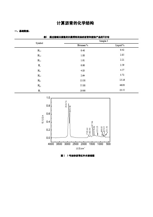
Cp——分子中的烷基碳数; CS——分子中的环烷碳数和烷基碳数之和; RA——分子中的芳香环数; RN——分子中的环烷环数; RT——分子中的总环数; fA——分子中的芳香碳数占总碳数的分率,简称芳碳率,又称芳香度; fN——分子中的环烷碳数占总碳数的分率,简称环烷碳率; fP——分子中的烷基碳数占总碳数的分率,简称烷基碳率; σ——芳香环系周边氢取代率; HAU/CA——芳香环系的缩合度参数; NCH2/NCH3——分子中亚甲基数与甲基数之比; NCH3——分子中甲基数; L——平均链长参数。
Liquid
0.083 0.601 0.235 0.055
H/C 原子比=11.47× 12/85.48=1.610 C/H 原子比=0.621
平均分子中的 CHSNO 个数:CT=85.71%× 826/12.01=59
HT=11.49%× 826/1.008=95 ST=0.3%× 826/32=0.08 NT=0.93%× 826/14=0.55 OT=1.57%× 826/16=0.81
通过核磁共振氢的归属得到的油砂沥青和液体产品的h分布symbolsamplebitumenliquida3048042a2188285a11012210002594834572643721338131655884693199023554000350030002500200015001000500000204060810波数cm14000350030002500200015001000500000204060810波数cm1油砂沥青和热转化后液体产品的核磁共振元素组成和平均相对分子质量samplebitumen8571114903093157826liquidproduct86681211025401710785352二计算过程
美国Eaton公司Bussmann系列14 x 51毫米模块插座保护器说明说明书

10080Product descriptionEaton’s Bussmann ® series 14 x 51 mm modular fuse holders are suitable for use with standard cylindrical fuse links and FW type ferrule fuse links.Their compact dimensions helps reduce space, allows for higher cable bending radius. Low watts loss and wide range of accessories make them ideally suited for most industrial applications.Standard features• Compact dimensions •Ventilation zones optimised for a better heatdissipation• I nbuilt padlocking facility • IP20 degree of protection (see details page 3)• Photovoltaic version rated at 1500 V d.c. (IEC only) for use with gPV fuse links • Flexibility to mount on DIN-Rail and/or screw mounting•Toolless DIN-Rail mounting, improves ease of use and reduces installation time and costs.14 x 51 mm Modular fuse holdersBUSSMANNSERIESTechnical Data 10080Effective October 201714 x 51 mm Modular fuse holdersEATON •Mounting 35 mm DIN-Rail or 2 x M4 panel mounting screws •Self-extinguishable UL 94-V0 rated polyester material •Storage & operating temperature rangeCH14D range:•Storage temperature -40ºC to +80ºC•Operating temperature -20ºC to +70ºCCHPV14 range - storage and operating temperature:• -20o C to +90o C (indicating)• -20o C to +120o C (non indicating)•RoHS compliant.Standards/Approvals• IEC 60269-1 and 60269-2• UL listed: file numbers E14853 for general purpose only;E348242 for photovoltaic gPV CHPV14 modular fuse holders • CCCPackaging• 1-pole: 6 per pack / 2-pole: 3 per pack• 3-pole: 2 per pack / 4-pole: 1 per packCatalogue symbol• CH14 (# of poles)DU: standard fuse holder• CH141D NXU: neutral fuse holder• CH14(#ofpoles)DNU: standard fuse holder and neutral• CH14(#ofpoles)DIU: fuse holder with neon indicator• CH14(#ofpoles)DNIU: fuse holder with neutral and neon indicator• CH14(#ofpoles)DMSU-F: fuse holder with microswitch (pre-breaking/fuse operation)• CH14(#ofpoles)DNMSU-F: fuse holder with neutral and microswitch (pre-breaking/fuse operation)• CH141DI-48U: fuse holder with LED Indicator• CH PV14(# of poles)U: suitable for photovoltaic fuse links Compatible fuse links• C14G and C14M: 14 x 51 mm fuse links• PV-(amp rating)A14F: Photovoltaic gPV Fuse links• FW Ferrule fuse linksT able 1. FW Ferrule fuse linksCatalogue number Maximumcontinuous fusecurrentCataloguenumberMaximumcontinuous fusecurrentFWH-5A14F 5 A FWP-5A14F 5 A FWH-10A14F10 A FWP-10A14F10 A FWH-15A14F15 A FWP-15A14F15 A FWH-20A14F20 A FWP-20A14F20 A FWH-25A14F25 A FWP-25A14F25 A FWH-30A14F24 A FWP-30A14F30 A FWX-5A14F 5 A FWP-32A14F32 A FWX-10A14F10 A FWP-40A14F40 A FWX-15A14F15 A FWP-50A14F49 A FWX-20A14F20 AFWX-25A14F25 AFWX-30A14F30 AT echnical data• Number of poles: 1 to 4• Rated voltageIEC ULCH14DU690 V a.c / 750 V d.c.700 V a.c.CHPV14U1500 V d.c.1500 V d.c.•Rated current•IEC: 50 A (a.c. and d.c.)•UL: 50 A•Rated power acceptance: 5 W to IEC 60269-2•Maximum power acceptance: 6.2 W •Protection index: IP20•Rated impulse withstand voltage (Uimp): 6 kV •SCCR Rating: 120 kA ac, 10 kA dc for CHPV14U •Cable size: 1.5 - 50 mm2•Torque settings:•Recommended torque setting 3.5 N•m •Maximum torque setting: 3.5 N•m23Technical Data 10080Effective October 201714 x 51 mm Modular fuse holdersEATON T able 2. T echnical DataOldCatalogue number NewCatalogue numberNumberof poles DescriptionNeutral onlyCH141BNX CH141DNXU 1Neutral cylindrical fuse holder Fuse holder onlyCH141B CH141DU 11-pole cylindrical fuse holder CH142B CH142DU 22-pole cylindrical fuse holder CH143B CH143DU 33-pole cylindrical fuse holder CH144B CH144DU 44-pole cylindrical fuse holder Fuse holder and neutralCH141BN CH141DNU 21-pole + neutral cylindrical fuse holderCH143BNCH143DNU42-pole + neutral cylindrical fuse holderFuse holder with neon indicatorCH141BI CH141DIU 11-pole cylindrical fuse holder with neon indicatorCH142BI CH142DIU 22-pole cylindrical fuse holder with neon indicatorCH143BI CH143DIU 33-pole indicator fuse holder with neon indicatorCH144BICH144DIU44-pole indicator fuse holder with neon indicatorFuse holder with neon indicator and neutralCH141BNI CH141DNIU 21-pole + neutral cylindrical fuse holder with neon indicatorCH143BNICH143DNIU43-pole + neutral cylindrical fuse holder with neon indicator Fuse holder with microswitchCH141BMS & CH141BMS-F CH141DMSU-F 11-pole cylindrical fuse holder with microswitch for remote fuse indication operationCH143BMS CH143BMS-FCH143DMSU-F33-pole cylindrical fuse holder with microswitch for remote fuse indication operationFuse holder with microswitch and neutralCH143BNMS-F &CH143BNMSCH143DNMSU-F 43-pole + neutral cylindrical fuse holder with microswitch for remote fuse indication operation Fuse holder with LED IndicatorN/A CHPV141DI-48U 11-pole cylindrical fuse holder with LED indicatorFuse holder for Photovoltaic applicationsCH141D-PV CHPV141U 11-pole cylindrical fuse holderN/A CHPV141IU 11-pole cylindrical fuse holder with neon indicatorN/A CHPV142U 22-pole cylindrical fuse holderN/ACHPV142IU22-pole cylindrical fuse holder with neon indicatorT able 3. AccessoriesCatalogue number DescriptionUnitpackingJV-LMulti-pole connector kit. One kit will gang up to 4-poles together 12CH14-SPS Microswitch to work on CH141D(I)U , 1 n/o + 1 n/c changeover type 3CH14-TPS Microswitch to work on CH143D(I)U , 1 n/o + 1 n/c changeover type3CH14-CTP IP20 Protection accessory, provides IP20 protection to terminals with 10mm 2 or less cable 12Technical Data 10080Effective October 201714 x 51 mm Modular fuse holdersEatonEMEA HeadquartersRoute de la Longeraie 71110 Morges, SwitzerlandEaton Electrical Products LimitedMelton RoadBurton-on-the-WoldsLeicestershire, LE12 5THUnited Kingdom© 2017 EatonAll Rights Reserved PDF Only Publication No. 10080 October 2017Eaton is a registered trademark. All other trademarks are property of their respective owners.Dimensional data - mmChanges to the products, to the informationcontained in this document, and to pricesare reserved; so are errors and omissions.Only order confirmations and technicaldocumentation by Eaton is binding. Photosand pictures also do not warrant a specificlayout or functionality. Their use in whateverform is subject to prior approval by Eaton.The same applies to Trademarks (especiallyEaton, Moeller, and Cutler-Hammer). TheTerms and Conditions of Eaton apply, asreferenced on Eaton Internet pages andEaton order confirmations.。
2化工压力管道设计-管道设计基础-管道规范和标准

JIS B2313 钢板制对焊管件 JIS B2316 承插焊管件
JIS B2401 O形环 JIS B2404 管阀兰用缠绕式垫片 JIS B3453 压缩石棉垫片
• 国际标准化组织( ISO) 的应用标准体系 ISO应用标准体系中常用的标准有:
ISO6708 管件 公称尺寸定义 ISO7268 管件 公称压力定义
• 美国应用标准体系ANSI中常用的标准有:
ANSI/ASME B36 . 10 无缝及焊接钢管 ANSI/ASME B36 . 19 不锈钢无缝及焊接钢管 ANSI/ASME B16 .9 工厂制造的钢对焊管件 ANSI/ASME B16 . 11 承插焊和螺纹锻造管件
ANSI/ASME B16 . 28 钢制对焊小半径弯头和回弯头 ASME/ANSI B16 . 34 法兰连接 、 螺纹连接和焊接连接的阀门 ASME/ANSI B16 . 5 管法兰和法兰管件
ISO4200 焊接和无缝平端钢管 尺寸和单位长度 ISO1127 不锈钢钢管 尺寸公差和单位长度质量 ISO3183 石油和天然气工业用钢管 IS06759 热交换器用无缝钢管 ISO7005- 1 金属管法兰
ISO7483 符合ISO7005标准的管法兰密封垫片 ISO3419 非合金钢和合金钢管件 ISO5251 不锈钢对焊管件 ISO7121 法兰型钢制球阀 ISO10497 阀门试验 防火试验要求
美国机械工程师学会(ASME)
ASME是世界上制定和出版规范和标准的主要组织之一, 1911年为制定蒸汽锅炉和其它压力容器的建造规定 ,ASME 成立了委员会 , 该委员会就是现在人们熟知的ASME锅炉和压 力容器委员会 , 负责锅炉和压力容器规范 。ASME相继成立了 其它的委员会 ,制定了许多其它的规范和标准 , 如ASME B31压力管道规范 。ASME遵照美国国家标准协会(ANSI) 批准的程序开展工作。
ASME第IX卷2010版与NBT 20002的比较研究报告

重要
类似
37
无
38
非重要
无
39 40
非重要 非重要
无 无
附录2:钨极惰性气体保护焊 (GTAW)
序 ASME焊接变素 41 改变清根方式 对于机械焊或 自动焊,摆动 的幅度、频率 或停留时间的 改变 每一侧的多道 焊改为单道焊 φ单丝 多丝 ASME ASME变 章节 QW410.6 QW410.7 素类型 非重要 NB/T 20002.3焊接变素 无 NB/T NB/T 20002.3章节 变素类型 主要差别说明
B
A
焊接的一般要求
ASME-IX QW篇
C
技能评定要求
E
标准焊接工艺规程
D
焊接资料
5
3、技术路线
ASME IX中有激光焊、电阻点焊、闪光焊、电容贮能焊、螺柱焊等要 求。 ASME中对于焊接工艺评定试件检验仅限于破坏性检验,无NDE要求。 NB/T 20002有焊材评定的要求,ASME中无此要求。 NB/T20002有车间评定的要求,ASME中无此要求。 NB/T 20002.3规定了产品焊接见证件的要求,ASME中未见有关产品焊 接见证件的规定。 焊接管理方面:NB/T 20002.3对需编制的文件、报告内容、评定有效 期有明确的规定,但是没有WPS和PQR的推荐表格。ASME IX中则在附录
5.5.4.8 5.3.3.3
重要
类似
5.5.4.9 5.3.3.4
重要
NB/T20002要求严格
5.5.4.11
重要
相同
附录2:钨极惰性气体保护焊 (GTAW)
序 ASME焊接变素 25 改变PWHT温 度和时间范围 ASME ASME变 章节 QW407.2 QW407.4 QW408.1 素类型 补充重 要 NB/T 20002.3焊接变素 同24 焊后热处理的温度循环发 生改变可能影响产品的最 终冶金状态(正火、淬火 和固溶热处理等),则焊 接工艺评定无效。 不涉及 保护气体和背面气体的评 定局限于评定所用气体的 标准型号。标准外的保护 气体仅限于评定试验所用 名义成分的气体。 对于有正面和背面保护, 气体或混合气体的名义化 学成分的改变(混合气体 的组分偏差遵守NB/T 20002.2的规定); 正面保护气体的流量比规 定的最小值降低了10%或 者更多; 保护气的名义成分的改变 无背面气体保护的评定适 用于带背面气体保护的焊 接工艺。 同30 NB/T NB/T 20002.3章节 变素类型 同24 重要 主要差别说明 NB/T增加升降温速率的要求
高准1700质量流量计2016年2月
1500 2500 &RPSDFWFRQWURO 紧凑型控制室 URRPWUDQVPLWWHU 变送器
3300 3500 )UHTXHQF\LQSXW 频率输入离散 GLVFUHWHFRQWUROOHU 控制器
DQGPHDVXUHPHQWSODWIRUP
注: • 每个螺丝端子连接可接受一条或两条 2.5 至 4.0 mm2(14 至 12 AWG)的实心导线,或一条或两条 0.34 至 2.5 mm2(22 至 14 AWG)的绞合导线。每个插塞式连接器可接受一条 0.20 至 2.5 mm2(24 至 12 AWG)的绞合导线或实心导线。 • 对于带一体式核心处理器(安装代码 C)的 1700/2700 型变送器,正常情况下无法接触到变送器与核心处理器之间的 4 线 连接。
适合仅要求质量流量或体积流量测量的应用
•
•
毫安和频率 / 脉冲输出 HART 或 Modbus 数字通讯 输出下述变量之一:质量流量、体积流量或气体标准体积流量
紧凑型一体式安装至传感器,可 360 度旋转;或通过现场安装选项安装至 4 线或 9 线高准传感器。 (1) 使用 35 mm DIN 轨道的紧凑小巧的分体式安装变送器,可连接至 4 线或 9 线高准传感器 I 类 1 区 /1 区本地操作界面:
波形因数包括带全套危险区域认证的坚固现场 安装件或用于经济型控制室机柜的 DIN 轨道套装 本地用户界面提供详细的操作员反馈和可达性 借助灵活的配置轻松地连接到新的或现有的高 准传感器
智能仪表检定:对整个系统的高级诊断Βιβλιοθήκη 适合无缝集成的连接和接口适应性
可就地运行或从控制室运行全面测试,让您对 仪表的功能和性能充满信心 验证仪表实际可完全达到安装之时的性能,90 秒 即可给您保证
星制造国际有限公司产品说明书 - GR14系列
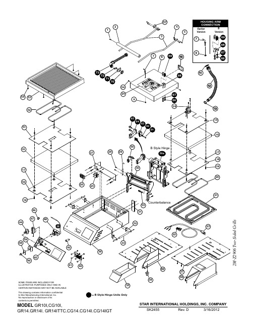
This drawing contains information confidential to Star Manufacturing International, Inc.IMPORTANT: WHEN ORDERING, SPECIFY VOLTAGE OR TYPE DESIREDPAGE 1 INCLUDE MODEL AND SERIAL NUMBER OF 4MODELPARTS LISTMarch 21, 2014, Rev. O14' TWO SIDED GRILLSFig. NoPart NoQtyDescriptionApplication12C-Z29922SCREW, HANDLE 22V-Z113951HANDLE, B-STYLE HINGECG142TB, CG14B, CG14E, CG14IB, CG14IGTB,CG14ITB, CG14ITGTB240, CG14ITLB, CG14ITSC,CG14TB, GR14B, GR14E, GR14IB, GR14ITB, GR14SNB, GR14TB2V-Z2989HANDLE - 14”, COUNTERBALANCE 2V-Z3413HANDLE - 14” S.S.GR14, GR14T, SER. # GRC00112 - 00138, GRC00778 - 00858, GRC00864 - 0125632B-Z113912ARM 14” SPT GR14SNB2B-Z2987ARM - 14”CG14EA, CG14IEA, GR14EA, GR14IEA, GR14C, CG14I, CG14IGT, CG14IT, CG14ITGT, GR14, GR14I, GR14IT 2B-Z3336ARMGR14SN2B-Z14019ARM, STANDARD 45 DEG.CG14DTB, CG14B, CG14E, CG14IB, CG14IT, GR14B, GR14E, GR14IB, GR14ITB42C-406374NUT 1/4-20 ACORN CAP MS ALL EXCEPT GR14SNB MODELS2C-08-07-0262WASHER52C-Z29924SCREW, ARM TO BRACKET2C-15234SCREW, .250-20UNC X .75 LG RHP B SERIES COUNTERBALANCE2C-08-07-0262LCKWSHR, .250 INTERLOCK TOOTH 6D9-Z20361HOUSING-TOP-14”D9-Z140201TOP HOUSING, LEFT, 14”CG142TB, CG14B, CG14E, CG14IB, CG14IGTB, CG14ITB, CG14ITGTB240, CG14ITLB, CG14ITSC,CG14TB, GR14B, GR14E, GR14IB, GR14ITB, GR14SNB, GR14TB72C-Z32002PIN - TOP HOUSING 82C-Z28552RETAINER RING92C-08-07-004021/4” NUT, USE PART NUMBER 2C-Z2820102A-Z38271PLATE, STAMPING - CONDUIT 112C-Z37802CONDUIT RETAINER 122E-Z28981CONDUIT ASSY. - PTFE 132E-Z37681CONDUIT LOCKNUT 14D9-04-GR-01661WIRE MOUNT15D9-GR00791TOP RETAINING PLATE AY/1416D9-Z28882INSULATION - 14”172A-Z66048SPACER - INSULATED PLATE 18D9-Z20751TOP ELEMENT/INS. PLATE/14192C-08-07-02858SCREW, ELEMENT RET. PLATE 20PS-Z19801ELEMNT REPL. KIT, 800W/120V CG14, CG14T, GR14, GR14IB GR14T, CG14IT-120V PS-Z2021ELEMNT REPL. KIT, 800W/240V CG14, CG14T, GR14, GR14TD9-GR0535ELEM\NT ASSY 800W/240V CG/GR14E-230V, CG/GR14E-240VPS-Z2391ELEMNT REPL, KIT, 1800W/240GR14I, GR14IT, CG14IGT, CG14ITGT, CG14I, CG14IT D9-GR0514ELEMENT, TOPCG14E-120V, GR14E-120V, GR14IE2M -Z 2906 T w o -S i d e d G r i l l sIMPORTANT: WHEN ORDERING, SPECIFY VOLTAGE OR TYPE DESIREDPAGE INCLUDE MODEL AND SERIAL NUMBEROF25MODELPARTS LISTMarch 21, 2014, Rev. O14' TWO SIDED GRILLS2M -Z 2906 T w o -S i d e d G r i l l sIMPORTANT: WHEN ORDERING, SPECIFY VOLTAGE OR TYPE DESIREDPAGEINCLUDE MODEL AND SERIAL NUMBER OF35MODELPARTS LISTMarch 21, 2014, Rev. O14' TWO SIDED GRILLSFig. NoPart NoQtyDescriptionApplication382A-Z14854FOOT, 1” ADJUSTABLE, 1/4” STUD CERTAIN APPLICATIONS 2A-Z11501FOOT, 1” SOLID RUBBER, 1/4” STUD ALLUMINUM PLATES2A-Z0314-1BASE, FOOT 4” CAST W/RUBBER FOOTCG14IB, CG14IGTB, CG14ITB, CG14ITLB, CG14ITSC, GR14IB, GR14ITB2A-Z12980 2.5” FOOT BASE, 3/8” STUD GR14I, GR14IT, CG14I, CG14IT, CG14IGT, CG14ITGT 2A-Z12946BASE, FOOT, NON-SKID CG14I, CG14IB, CG14IE, CG14IEGT, CG14IGTB, GR14I GR14IB, GR14IE, GR14ITB, (mfg after 4-2010) 39D9-GR00611BODY ASSY. - 14”D9-GR0184BODY ASSY GR14SN402J-Z18361TIMER CONTROL CG14T, CG14IT, CG14IGT, GR14T, GR14IT412K-Z19714SPACERCG14T, CG14IT, CG14IGT, CG14E, GR14T, GR14IT, GR14E,422J-Y66891PILOT LIGHT, 120V CG14, GR14 (120V MODELS)2J-Y6690PILOT LIGHT, 240V GR14I, CG14IGT, CG14I, CG14, GR14 (240V)44PS-GR02241RKER SWITCH RPL 14” KIT CG14T-120V W/SERIAL NO BELOW CGC25308CG14IT-120V W/SERIAL NO BELOW CGC24701GR14T-120V W/SERIAL NO BELOW GRC23789CG14IT-240V W/SERIAL NO BELOW CGC245592E-Z6863SWITCH 3 POS, DPDT CG14T, CG14IT, CG14IGT, GR14T, GR14IT 2E-Z3808SWITCH - 30A@120V CG14E-120V, GR14E-120V452M-Z30501OVERLAY - 14” NO TIMERGR14I, CG14IGT, CG14I, CG14, CG14B, GR14, GR14B, CG14GTB 2M-Z3816OVERLAY - 14” w/2 MANUAL TIMERS CG14-2T2M-Z3929OVERLAY, CHIPOTLE GR14SN, GR14SNB2M-Z6870OVERLAY - 14” w/TIMER GR14IT, CG14ITGT, CG14IT, CG14T, GR14T, GR14TB 2M-Z12002OVERLAYCG14E, GR14E 2M-Z18461LABEL ON & OFFCG14E, GR14E462I-05-07-00131RUBBER BOOT, SWITCH 472R-Z18541KNOB-CONTROL482T-64471THERMOSTAT 118V-236V 492A-Z30261HALF CLIP50D9-Z133381BTM. INSULATION RET. PLT. 14”51D9-Z133381BTM ELEMENT RET. PLATE 14”522N-Z19811BTM ELEMENT, HEATING, 1000W/120CG14, CG14T, GR14, GR14IB, GR14T, CG14IT-120V 2N-Z2022BTM ELEMENT, HEATING, 1000W/240CG14, CG14T, GR14, GR14T D9-GR0534BTM ELEMENT ASSY, 1000W/240GR14E-240V2N-Z2392BTM ELEMENT, HTG, 1800W/240V GR14I, GR14IT, CG14IGT, CG14ITGT, CG14I, CG14IT D9-GR0513BTM ELEMENT ASSYCG14E-120V, GR14E-120V, GR14IE 532F-Z19451CASTING, SM. BOT., ALUM.-14”GR14, GR14T, CG14GTB 2F-Z1947CASTING, GR. BOT., ALUM.-14”CG14, CG14T2F-Z1949CASTING, SM. BOT., IRON-14”GR14I, GR14IT, CG14IGT, CG14ITGT 2F-Z1951CASTING, GR. BOT., IRON-14”CG14I, CG14IT542C-Z58838SCREW 10-24X1/2 FZA 55PS-GR1342ROLLER BEARING KIT2M -Z 2906 T w o -S i d e d G r i l l sIMPORTANT: WHEN ORDERING, SPECIFY VOLTAGE OR TYPE DESIREDPAGE INCLUDE MODEL AND SERIAL NUMBEROF45MODELPARTS LISTMarch 21, 2014, Rev. O14' TWO SIDED GRILLS2M -Z 2906 T w o -S i d e d G r i l l sIMPORTANT: WHEN ORDERING, SPECIFY VOLTAGE OR TYPE DESIREDPAGE INCLUDE MODEL AND SERIAL NUMBEROF55MODELPARTS LISTMarch 21, 2014, Rev. O14' TWO SIDED GRILLSFig. NoPart NoQtyDescriptionApplicationNI 2R-09-WB-00062KNOB-BLACK (NOT SHOWN)CG14-2TNI2V-Z30272CROSS SUPPORT (NOT SHOWN)GR14I, GR14IT, CG14I, CG14IT, CG14IGT, CG14ITGT NI D9-GR01081FACEPLATE ASSY. - 14” NO TIMER GR14I, CG14IGT, CG14I, CG14, GR14NI D9-GR01781FACEPLATE ASSY. - 14” 2 TIMERS CG14-2T NI D9-GR01851FACEPLATE ASSY, - 14”GR14SNNI D9-GR02101FACEPLATE ASSY. - 14” w/TIMER GR14IT, CG14ITGT, CG14IT, CG14T, GR14T NI D9-Z120271PROBE BRACKET - BOTTOM CG14E, GR14ENI D9-Z30281SIDE SUPPORT (NOT SHOWN)GR14I, GR14IT, CG14I, CG14IT, CG14IGT, CG14ITGT NI D9-Z30291PART SUPPORT (NOT SHOWN)GR14I, GR14IT, CG14I, CG14IT, CG14IGT, CG14ITGT NIZ1-70-07-03431SWITCH GUARDCG14E, GR14E2M -Z 2906 T w o -S i d e d G r i l l s。
- 1、下载文档前请自行甄别文档内容的完整性,平台不提供额外的编辑、内容补充、找答案等附加服务。
- 2、"仅部分预览"的文档,不可在线预览部分如存在完整性等问题,可反馈申请退款(可完整预览的文档不适用该条件!)。
- 3、如文档侵犯您的权益,请联系客服反馈,我们会尽快为您处理(人工客服工作时间:9:00-18:30)。
2010年股市收官总结沪指全年跌14.31%-股票频道-和讯网2010年股市收官总结沪指全年跌14.31%和讯股票消息回顾2010年,纵观全年表现,沪指从年初的3277点,到今日的2808点,经过了大跌大涨的洗礼之后,A股市场2010年无奈地交出了一份惨淡的答卷,沪指今年以来下跌14.31%,在全球股票指数涨幅排名中列倒数第三,仅略强于身陷欧债危机的希腊和西班牙。
行业的表现显示出巨大的差异,电子元器件年内涨幅达36%,而钢铁、地产等权重板块则跌幅超过20%。
最牛的个股当属广发证券全年上涨超500%,而最熊个股是鞍钢股份全年下跌近50%。
而据和讯调查,总体54%的投资者表示获利。
创业板、中小板指数以及大批股票在2010年创出历史新高,可以想象,展望2011年,有更多的精彩值得期待!投资者2010年收益调查2010年和讯调查说明:2010年市场走势呈现先抑后扬走势,此前的上半年调查中,70%以上投资者均出现亏损,而至下半年,总体获利的投资者已经占到半数以上达到59.9%。
2010年影响股市大事件盘点2010年影响股市大事件盘点总的来说,2010年资本市场政策频繁,创新较多,年初1月8日融资融券、股指期货获批,市场解读成利好,股指高开3%以上,但当时投资者却没有意识到,当天的高点3306点将是2010年全年的最高点,不过当时市场预期四大国家级区域振兴规划将出台,罗顿发展1个月翻番的走势也令人意识不到一个即将下跌半年的大盘走势即将来临。
4月16日股指期货正式推出,中国股市结束单边做多才能获利的历史,市场也因此恐慌,展开一波年内最大的跌幅走势。
而且,在下跌的5、6月,屋漏偏逢连夜雨,农行即将上市,市场对农行也有恐惧心理,不过恰恰因为此,7月15日农行上市股指反而见底,展开反弹行情。
反弹持续至11月中旬,国内通胀形势愈发严峻,11月18日国务院表态抑制通货膨胀,股市期市受挫,市场就此展开大幅调整,并且一直持续至12月底未有止跌迹象,而12月27日的央行加息,再次推波助澜令得市场结束整理1个月的平台向下突破。
展望2011,从紧的货币政策、扑朔的国际局势、转型的经济模式均将令得2011年充满不确定性,预计2011年的股市将在曲折中前行,波动空间2500—3700。
详细盘点:一、1月8日期指和融资融券双双获批1月8日期指和融资融券双双获批证监会8日宣布,股指期货与融资融券正式获批。
股指跳空高开形成年内最高点。
二、1月15日四大国家级区域振兴规划有望出台罗顿发展飙升引爆区域振兴规划炒作热情区域振兴规划点燃资本热情。
西藏、新疆、四川和重庆、海南等板块涨幅在所有地域板块中最为明显。
其中西藏板块两周内累计涨幅已达12.57%。
罗顿发展更是随后1个月内走势翻倍。
三、股指期货4月16日正式推出股指期货4月16日正式推出2010年4月16日,这个日子被载入史册,这一天,经过8年酝酿、4年筹备的首个金融期货――沪深300股票指数期货合约正式上市。
而有了股指期货,当股价过高和过低时,股指期货的价格发现功能和做空机制就可以起到“纠偏”作用,有效抑制股价非理性的上涨和下跌,改变我国股票市场“单边市”现状。
有了股指期货,机构投资者在牛市中能够赚到收益,在熊市中也有了避险手段,更多长期资金愿意入市,有效扩大市场容量,提高市场稳定性。
股指期货的推出也将改善百姓收入,特别是投资收益方面。
有期货专家指出,股指期货作为一种重要的金融衍生品,可以让金融机构设计金融产品时更加丰富多元,我国面向大众的理财产品中,收益超过通货膨胀率低于高风险的股票投资基金的5%至15%的产品基本空白,然而有了股指期货,就能组合出这个收益段的产品,丰富了理财产品。
四、7月15日农行上市此前发行超高中签率7月15日农行上市2010年7月15日,农行登陆A股,至此,中国大型商业银行全部上市。
农行上市是各方力捧的结果,机构投资者显示出觉悟,农行压低了自身的饕餮之胃,最后市场勉强首肯。
农行A股网上网下合计冻结资金4800亿,远低于市场预计的超万亿规模;网上中签率约为9.29%,创出自2006年6月A股市场新股发行"新老划断"以来的第二高,仅次于华泰证券发行时的网上中签率。
超高的中签率代表了市场普遍对农行破发的担忧,不过农行上市,大盘见底,股指反而走出了一波像样的反弹行情。
五、三网融合提升传媒板块投资机会传播指数全能持续走出上升趋势2010年伊始,国家就陆续出台关于三网融合的各项政策措施,这标志着三网融合在中国已经步入实质阶段。
三网融合符合当今社会发展和消费倾向,随着相关技术的成熟,其满足了社会大众对多方位、多层次、多渠道下语音、网络、多媒体以及融合产品的需要。
首先,三网融合将打破垄断,给消费者带来更大的社会福利。
政府推动三网融合的一个重要目的是促成多家市场竞争主体,形成市场良性竞争。
其次,三网融合提供了更为丰富的产品和服务,满足了社会大众的深层次需求。
三网融合最大的特征是融合,这不仅包含网络融合,更包含业务和产品的融合。
最后,三网融合降低了消费成本,使消费者便利性大大提高。
以往一个家庭要面对移动运营商、固定运营商、广电企业等。
从市场角度来看,三网融合将带动整条产业链的发展,包括内容提供商、服务提供商、运营商以及光纤通讯设备制造商在内的多家上市公司均将受益。
今年市场针对三网融合板块,出现了多次资金炒作的行情。
六、风雨创业板一周年纪念创业板一周年截至2010年9月30日,正式挂牌交易的123家创业板公司中,将近92%左右的公司均为民营企业。
创业板的推出,为民营企业发展提供了最为宝贵的融资渠道。
数创业板通过对资本的聚集能力,为民营经济中的这些“小巨人”企业的高速成长提供了充足的资金保障。
创业板通过资源配置功能,支持了区域支柱产业的发展,进一步加速了区域产业经济结构的调整和升级,而随着创业板企业的不断发展,这些公司将逐渐成为促进区域经济产业升级进步的生力军。
走势上创业板更是牛气十足,在成立1周年之后,创业板指数突破此前历史高点1129.69点,创出新高。
七、四大银行再融资风云交行配股此后熊途漫漫2010年,国务院同意工、建、中、交四大银行总规模为2870亿元的再融资计划,用于补充资本金,以满足天量信贷投放以及对资本充足率的要求。
而中行发行400亿元可转债获批,打开了大银行的融资窗口。
回想两年前,中国平安提出的1200亿元融资计划,触发了随后中国股市的一路狂泻。
而当年的平安和此时的四大行相比,实在是小巫见大巫。
资本市场的恐惧动容在所难免。
虽然在资本市场上融资不仅是上市公司发展壮大的必要途径之一,也是投资者分享投资收益的重要方式。
但这些银行股融资后表现乏善可陈,交行六月配股后,熊途漫漫。
八、超级细菌炒作联环药业短期快速飙升联环药业借超级细菌大幅飙升“超级细菌”在中国现身,其基因分别在宁夏两名新生儿和福建一名老年癌症晚期患者样本中。
自此之后,国内医药股市再度风起云涌,超级细菌概念股揭竿而起,迎来“第二春”。
在8月份因硫酸粘菌素而被称作“超级细菌第一股”的联环药业再次被推向高峰,涨幅达到155.8%,这仅仅是概念股中表现抢眼的一只。
此时股票市盈率的高低无关紧要,主力唯一在乎的是能否在高位成功出货。
投资者需要吸取的经验就是大幅上涨的股票风险也将相当巨大。
九、妖股壹桥苗业(002447,股吧)涨停止步“禁炒令”妖股壹桥苗业涨停止步禁炒令2010年9月9月,在“禁炒令”以及严密监控下,壹桥苗业收于94.27元,仍微涨0.5%。
被称之为“妖股”的壹桥苗业自7月13日上市以来,最高涨幅达231.02%。
其从发行价28.98元一路涨至9月3日的高点125.82元,跻身“百元股”俱乐部。
在游资爆炒之下,9月3日,深圳证券交易所向各大券商发出监管函——要求“人盯人”监控壹桥苗业股票的交易账户。
自此,壹桥苗业,众游资慌忙逃散,股价接连挫败,可谓是爬得越高,摔得越惨。
十、物联网中国经济新的增长点新大陆借物联网概念3季度连续上涨物联网,被称作全球下一个万亿元级规模的新兴产业之一。
衣服会“告诉”洗衣机对颜色和水温的要求;公文包会“提醒”主人忘带了什么东西;当货车司机和别人扯闲话时,货车会装作老板的声音怒吼“笨蛋,该发车了!”……国际电信联盟曾在报告中这样描绘物联网时代的神奇图景,而这一切将在物联网应用加速推进的中国成为现实。
分析人士表示,未来几年将是中国物联网应用的迅猛发展期,物联网技术与实际产业的结合将成为中国经济新的增长点。
十一、国家鼓励多线布局新能源汽车成飞集成引爆投资锂电热成飞集成“电”力十足随着新能源汽车成为国家战略性新兴产业,针对该行业的政府归口管理也正在加紧进行。
工信部官员表示,目前国家正在制定相应的技术标准、市场准入门槛和产业政策,为了避免盲目投资和重复建设,相应的管理办法、制度和方案都在研究中。
据消息人士透露,中国汽车产业确定了新的中期发展目标,即用两个“五年”时间,使中国汽车技术整体水平达到世界先进水平,包括传统能源汽车和新能源汽车技术。
而成飞集成在“拟非公开发行不超过1.06亿股,发行价不低于每股9.70元,募集资金总额不超过10.2亿元,扣除发行费用后将全部用于增资中航锂电建设锂离子动力电池项目”的一纸公告下,连续飙升,但投资者需要冷静的是,公司预期项目建设周期超过3年,而且目前并没有通过银行贷款先实施的计划,因此项目的真正完成还需要相当长的时间,加上项目审核的漫长过程,即使一路顺风完全建成也需要4年的时间,那时已经到了2014年,而那个时候行业的变化谁也说不准,因此公司预期的收益并不靠谱。
概念炒作,很大程度上是画饼,而实质性业绩的提升,任重道远。
十三、中东有石油中国有稀土广晟有色一年上涨6倍“中东有石油,中国有稀土。
”这是邓小平1992年南巡时说的一句名言。
我国稀土产业在世界上拥有多个第一:资源储量第一,占70%左右;产量第一,占世界稀土商品量的80%至90%;销售量第一,60%至70%的稀土产品出口到国外。
