南方手持激光测距仪pd58a
FNB58 USB快充测试仪 使用说明书

USB快充测试仪 FNB58目 录五、 外观结构03六、 技术指标044.0.2 快充触发类034.0.3 线材鉴别类024.0.4 杂类037.0.2 监测页面057.0.3 波形页面067.0.4 应用页面06058.0.1 自动检测078.0.2 PD触发器078.0.3 小米PD触发器088.0.5 QC3.0触发088.0.4 QC2.0触发088.0.6 FCP触发098.0.7 SCP触发098.0.8 AFC触发098.0.9 VOOC/WARP触发098.0.10 SVOOC 1.0/SVOOC 2.0触发0910.0.2PD监听器1210.0.3PD转换器1310.0.4USB-C电子标签13十、工具箱119.0.2电池容量计算109.0.3离线记录10九、能量统计0911.0.2记录1611.0.3触发1711.0.4系统1711.0.5关于1710.0.7模拟APPLE 2.4A15141410.0.5读取DASH线缆10.0.6模拟DASH一、版本与更新由于仪表功能极多且软硬件更新频繁,说明书随时可能更新,请知悉。
请在官网上获取最新的更新信息。
二、概述FNB58 USB测试仪是一款高可靠性、高安全性的USB电压电流检测表及移动通信终端快充触发仪。
具有2.0寸全彩超宽视角TFT LCD显示屏及集成USB-A、Micro-USB、Type-C接口。
使用外置16位ADC,PD协议物理芯片。
可用于测量USB接口、手机充电器、U盘等产品的供电或耗电情况;可用于测量手机充电功率、移动电源输入输出状况;可用于充电器快充协议测试。
本使用说明书包括有关的安全信息、警告提示以及常见的异常状况解决方案,请仔细阅读有关内容并严格遵守所有的警告和注意事项。
三、注意安全事项●监控接口请勿接入超过28V的电源;●PC联机端口请勿接入超过16V的电源;●同一时间只能有一对监控接口(一个输入口、一个输出口)工作,当已有一对监控接口工作时,禁止在其他监控接口接入设备。
LS 系列激光雷达 - 测量 D2 型 使用说明书
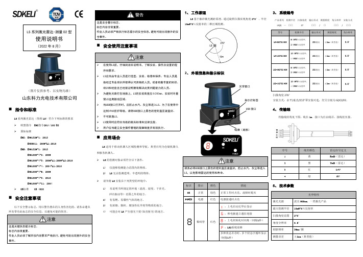
LS 系列激光雷达-测量D2型使用说明书(2022年8月)(图片仅供参考,以实物为准)山东科力光电技术有限公司⏹指令和标准LS 系列激光雷达(简称LS)符合下列标准的要求 欧盟指令EMC指令2014/108/EC国际标准EMI:EN61326-1:2013EN55011:2009+A1:2010EMS:EN61326-1:2013EN61000-4-2:2009EN61000-4-3:2006+A1:2009+A2:2010EN61000-4-4:2004+A1:2010EN61000-4-6:2009EN61000-4-8:2010EN61000-4-11:2004GB标准GB 4028⏹安全注意事项以下安全警示标志,用以警告潜在的人身伤害危险,请务必遵从所有带有此标志的安全信息,以避免可能的伤害。
注意这是关键信息提示标志。
警告⏹安全使用注意事项注意在使用LS前,仔细阅读本说明书,了解安装、操作及设置的程⏹应用场合LS 适用于移动机器人区域检测和导航,典型应用为仓储机器人和服务机器人。
LS 的检测对象必须符合以下条件:1)仅能够检测能力范围内的物体。
2)LS 无法检测透明、半透明的物体。
请勿将LS 安装在下列类型的环境中:1)本说明书所规定的环境(温度、湿度、干涉光、冲击振动等)范围之外的地方。
2)有易燃、易爆性气体的地方。
3)有浓烟、微粒、腐蚀性化学剂等物质的地方。
4)可能会对LS 产生强光干扰(如直射光)的地方。
1、工作原理LS 基于脉冲激光测距原理,通过旋转扫描实现角度270°、半径10m@70%反射率的二维区域检测。
2、外观信息和指示标识多种状态并存时,3、系统编号扫描角度270°安装方式:水平/垂直/防护罩安装可选,代号分别为SZ/CZ/FZ 。
4、传输线传输线结构见下图,线长1m,接口为自由线芯,接线柱压接。
5、技术参数注意请务必将USB接口上黑色的密封盖压紧盖好,防止水汽、灰尘等进入光学窗口指示灯标签USB 接口铭牌(底部)6、测量数据7、串口参数波特率配置,默认460800;详细通信协议见《科力串口通信协议.xlsx》。
海康威视 DS-2DY9188-AIA 2MP 36X激光超低光环境定位系统说明书

Key Features•1920×1080Full HD output •Ultra-low illumination •Wide movement range•36X optical zoom,16X digital zoom •Up to 1000m IR distance•True Day/Night,true WDR,3D DNR,Defog •3D intelligent positioning •Triple stream •Audio/Alarm I/O•Wiper for self-cleaningHikvision darkfighter series DS-2DY9188-AIA 2MP 36X Laser Ultra-Low Illumination Positioning System is able to capture high quality images in dim light environment. It’s laser IR light can reach up to 1000m IR distance. Embedded with 1/1.9’’ progressive scan CMOS chip makes true WDR and 2MP real-time resolution possible. With the 36X optical zoomDay/Night lens, the positioning system offers more details over expansive areas.Hikvision darkfighter series DS-2DY9188-AIA 2MP 36X Laser Ultra-Low Illumination Positioning System also features Smart Defog and EIS (Electronic Image Stabilization), which can further supported to improve image quality in challenging conditions.Function DescriptionIR function:•0 Lux minimum illumination•High performance laser IR LED, up to 1000m IR distance •IR light MTBF reaching up to 30,000 hoursBasic function:•High performance CMOS, up to 1920x1080 resolution •±0.1°Preset Accuracy•ONVIF(Open Network Video Interface Forum),CGI(Common Gateway Interface), PSIA(Physical Security Interoperability Alliance), to ensure greater interoperability between different platforms and compatibility•3D intelligent positioning function•3D DNR•IP66 standard•7 alarm inputs and 2 alarm outputsSmart function:•Smart image processing: support defog, HLC/BLC •Smart codec: low bit rate, ROI•Smart detection: support Face detection, Intrusion detection, Line crossing detection, Audio exception detection, Region entrance detection, Region exiting detectionCamera function:•Auto iris, auto focus, auto white balance, backlight compensation and auto day & night switch•Min. Illumination: Color:0.002Lux @ (F1.5, AGC ON), B/W:0.0002Lux @(F1.5, AGC ON)•Support 24 privacy masksPTZ function:•360°endless pan range and +40°~ -90°tilt range •0.1°~ 100°/s Manual Pan Speed and 0.1°~ 40°/s Manual Tilt Speed•300 presets programmable; preset image freezing capability•8 patrols, up to 32 presets per patrol•4 patterns, with the recording time not less than 10minutes per pattern•Proportional zoom function•Park action: auto call up of PTZ movement, after a defined time of inactivity•Power-off memory: restore PTZ & Lens status after reboot Network function:•H.264/MJPEG video compression•H.264 encoding with Baseline/Main/High profile•ROI(Region of Interest) encoding(support 24 areas with adjustable levels)•Built-in Web server•Onboard storage, up to 128GB•Support up to 8 NAS storage; Edge recording(transmit the videos from SD card to the NAS after network resumed)•HTTPS encryption and IEEE 802.1X port-based network access control•Support trip-streams•Multiple network protocols supported: IPv4/Ipv6, HTTP, HTTPS, 802.1X, QoS, FTP, SMTP, UPnP, SNMP, DNS, DDNS, NTP, RTSP, RTP, TCP, UDP, IGMP, ICMP, DHCP, PPPoE•1 audio input and 1 audio outputModel DS-2DY9188-AIA Camera ModuleImage Sensor1/1.9’’ Progressive Scan CMOS Max.Image Resolution1920 X 1080Min.Illumination Color:0.002Lux @ (F1.5, AGC ON) B/W:0.0002Lux @(F1.5, AGC ON)Day&Night ICRFocus Mode Auto / Semiautomatic / ManualShutter Time50Hz: 1/1-1/30,000s; 60Hz: 1/1-1/30,000sS/N Ratio>52dBDigital Zoom16XWhite Balance Auto / Manual /ATW/Indoor/Outdoor/Daylight lamp/Sodium lamp AGC Auto / ManualLensFocal Length 5.7-205.2, 36xAngle of View58.7-2.0 degree (Wide-Tele)Min.Working Distance10-1500mm(Wide-Tele)Aperture Range F1.5-F3.4ImageMain Stream 50Hz:25fps(1920×1080), 25fps(1280×960), 25fps(1280×720) 60Hz:30fps(1920×1080), 30fps(1280×960), 30fps(1280×720)Sub Stream 50Hz:25fps(704×576), 25fps(352×288), 25fps(176×144) 60Hz:30fps(704×480), 30fps(352×240), 30fps(176×120)Third Stream 50Hz: 25fps(1920×1080), 25fps(1280×960), 25fps (1280×720), 25fps(704×576), 25fps (352×288), 25fps (176×144) 60Hz: 30fps(1920×1080), 30fps(1280×960), 30fps (1280×720), 30fps(704×480), 30fps (352×240), 30fps (176×120)Image Compression H.264(Baseline, Main, High Profile)/MJPEG/MPEG4Audio Compression G722.1/G.711ulaw/G.711alaw/MP2L2/G.726/PCMSVC SupportProtocols IPv4/IPv6,HTTP,HTTPS,802.1x,Qos,FTP,SMTP,UPnP,SNMP,DNS,DDNS,NTP,RTSP,RTP,TCP,UDP,IGMP,ICMP,DHCP,PPPoE Standard ONVIF, PSIA, CGI, GenetecOthers Defog, EIS, Privacy Mask, 3D DNR, BLC, true WDRSmart FeaturesSmart detection Face detection, Intrusion detection, Line crossing detection, Audio exception detection, Region entrance detection, Region exiting detectionROI encoding Support 24 areas with adjustable levelsInfraredIR Distance1000mIR Intensity Automatically adjusted, depending on the zoom ratioSmart IR SupportPan and TiltMovement Range Pan: 360°endless, Tilt: +40°~-90°Movement Speed Pan: 0.1°-100°/s, Tilt: 0.1°-40°/sNumber of Preset300Patrol8 patrols,up to 32 presets per patrolPattern 4 patterns, with the recording time not less than 10 minutes per patternPower-off Memory SupportPark SupportProportional Zoom SupportPTZ Position Display On / OffSystem IntegrationMenu English3D Positioning SupportPreset Freezing SupportScheduled Task SupportAlarm I/O7 alarm inputs, 2 alarm outputs, alarm linkageAlarm Action Preset / Patrol / Pattern / SD card recording/ Aux output/ E-map on ClientAudio I/O1/1Ethernet10Base-T / 100Base-TX, RJ45 connectorCVBS Output 1.0V[p-p] / 75Ω, NTSC (or PAL) composite, BNCRS485Half duplex, HIKVISION, Pelco-P, Pelco-D, self-adaptiveOnboard Storage Built-in Micro SD/SDXC card slot,up to128GB,edge recordingNumber of Simultaneous LiveUp to20ViewUser/Host Level Up to32users,3Levels:Administrator,Operator and UserGeneralPower AC24V,Max.110WWorking Temperature/Humidity-40°C~65°C,humidity95%or lessProtection Level IP66 standard, TVS 6,000V lightning protection, surge protection and voltage transient protection Dimensions(mm)251×508×360Weight(approx.)20kgDimensionsUnit:mmUnit:mm。
建筑工程测量教案4章_南方手持激光测距仪PD-58A
• • • • • • • •
2) 距离测量 (1) 单次距离测量 指示激光关闭时,按 键为打开指示激光 将指示激光对准目标,再按 键测距 屏幕主显示区——基准边至目标的距离值 并关闭指示激光 指示激光已开时,按 键为关闭指示激光 正在测距时,按 键为停止测距并关闭指示激光。
• • • • • • • •
• • • • • • • •
6) 倾斜、平距与距离放样测量 内置倾斜传感器测量激光束竖直角 范围——±45o或±100%,误差——±0.3o或0.5% 倾角单位——十进制度o或%,菜单模式MENU2设置 (1) 倾斜测量 按 键启动倾斜传感器,屏幕顶部显示图标 辅助显示区第一行——实时显示仪器底边当前倾角 按 键测量
• 放样测量案例 • 主显示区值=实测距离−当前放样值
• • • • • • •
7) 间接测量 按 键进入间接测量模式 通过测量2~3个距离值计算—— 另一个高差,水平方向距离,面积 连续按 键可使测量功能按 “单勾股测量→双勾股测量→组合勾股测量→ 三角形测量→梯形测量1→梯形测量2”顺序循环切换
• • • •
(1) 单勾股测量 按 键进入“单勾股测量”界面,左侧显示图标 瞄准A点,按 键测量斜距OA 仪器水平,按 键测量平距OB。
• 单勾股测量案例 • 辅助显示区——三角形斜边,水平边值 • 主显示区——高差x的值
• • • • •
(2) 双勾股测量 按 键进入“双勾股测量”界面,左侧显示图标 瞄准A点,按 键测量斜距OA 仪器水平,按 键测量平距OB 瞄准C点,按 键测量斜距OC
• 4) 设置测距基准边 • 按 键切换测距基准点——后端/前端 • 打开延长板,测距基准点自动设置为延长板尾端。
• 按住 键2s,进入菜单模式,将MENU6页设置为“ON” • 启动三角架测量 , 测距基准三脚架连接螺丝接口中心。
SE2L2IDEC安全激光扫描器产品说明书
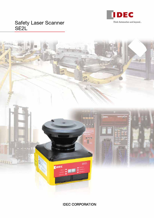
Safety Laser Scanner SE2L2IDEC’s safety products for safe and productive production linesStop area can be made smaller by detecting approach at the additional protection zone to start slowdown.(Conventional configuration of one protection zone +two warning zones is possible)RF1V force-guided relay(4-pole/6-pole)One SE2L protects a wide area (270º and 5m) and can be used in a variety of applications such as large sized systems or long conveyor lines.*1: average stride length (70 cm) of a 170 cm personCan interrupt a small load directly.Area Protection Ensures the safety of humans in a hazardous area, or those approaching the machine.RF2 force-guided relay (2-pole)Can be used as interface relays to send inputsignals to a controller, or to amplify current for driving a contactor.∗1A maximum of four SE2Ls can be interconnected using RS-485 for master/slave operation.3An SE2L can monitor two separate hazardous areas to stop machines when detecting the access of humans. No reflective sensor is necessary, thus eliminating the need of optical axis alignment. Can replace two light curtains.FS1A Safety ControllerLD6A LED SignaLight TowersReference monitoring function ensures safety bydetecting the positional change of SE2L or reference boundary, such as a door’s opening/closing status.Dual protection function A variety of safety products can be connected to the controller equipped with various control logics.Used to indicate the status ofprocesses. Visible even at a distance.By disabling some areas of protection zone, muting function allows objects to enter the hazardous area without stopping the machine.With override function, when stopped by errors at muting status, the work can be moved easily.Access Protection Allows only objects to pass through. Detects the access of humans.Utilize distance measurement dataA maximum of 32 area patterns can be configured/switched according to the mobile application suchas AGV, ensuring the optimum protection in variousapplications.EDM function monitors the status of externaldevices, enabling monitoring of welded contacts andsuch.Pulse signals from an incremental encoder can be sentto the SE2L directly without a controller, enabling toswitch areas easily depending on the speed.During safety protection, the SE2L can send outdistance measurement data through the Ethernetport, in order to obtain the data of the obstacles.Emergency Stop SwitchesXW/XN/X6A variety of models to choose from.Force-guided relayCollision AvoidanceIDEC’s safety productsfor safe and productiveproduction linesProtects humans from colliding.Also prevents loads on fromfalling.45Operational status is displayed on the SE2L. It can also be displayed on PC to monitor errors and data log for easy trouble shooting.Checks dust in air with signals and reduces unintendeddetection. Safety function is not impaired.Easy-to-use configuration and useful functions for simple and comfortable maintenance.IDEC Safety Solution− Safety system − Safety consulting − Risk assessment − Safety seminarsOptical window can be replaced by the user, reducing downtime and cost. A cover bracket to protect the SE2L for damage by collision is also available.Cover Bracket Optical WindowIDEC —Committed to creating the optimum safety environment —both for humans and systems.SE2L Safety Laser ScannerPackage Quantity: 1• See product catalogs or IDEC's website for detailed part no.Safety Products6SE2L Safety Laser ScannerNote 2: Additional distance of 200 mm is needed when the SE2L operates under high reflective background.Note 3: Total current supply of OSSD output and warning output should be below 1.0A.Note 4: The angle between the sensing plane and the light source should be more than 5 degrees.78SE2L Safety Laser ScannerAll dimensions in mm.DimensionsSafety Laser ScannerCover BracketSE9Z-HS2-CM01• Used to protect the optical window in combina-tion with base mounting bracket or rear mounting bracket.96.250254-M515ø854090.77091817(10)(30)29.53321Rear Mounting BracketSE9Z-HS2-BK026866204548.22513415061.225(93.2)(101.2)284-ø5.3SE2L Mounting Holes4-ø5.3Cover Bracket Mounting Holes7.5°7.5°7.5°7.5°Base Mounting BracketSE9Z-HS2-BK011106860286611013010(18)3-ø5.3604570257.5°7.5°48.225364-ø5.3 SE2L Mounting Holes4-ø5.3Cover Bracket Mounting Holes9SE2L Safety Laser ScannerWiring Examplesa) When using 32 scanning areas (e.g. AGV)b) When using muting/override/EDMc) When switching 32 scanning areas using an encoderIDEC safety products Safety Controller: FS1A E-STOP: X seriesIDEC safety productsSignaLight w/alarm: LD6A PLC: FC6A LED pilot light: AP22Force-guided relay: RF2IDEC safety productsSignaLight w/alarm: LD6A PLC: FC6A Muting sensor: SA1E Muting sensor lamp: HW1P-5Force-guided relay:RF210SE2L Safety Laser ScannerInput/Output CircuitOSSD/WARNING outputs are Nchannel MOSFET outputs.Input CircuitAvailable for are input, EDM1, EDM2, RESET1, RESET2, MUTING1, MUTING2, MUTING3, MUTING4, OVERRIDE1, and OVERRIDE2.RES_REQ1, RES_REQ2, MUT_OUT1, MUT_OUT2 outputs are PNP outputs.IDEC safety products SignaLight w/alarm: LD6A PLC: FC6A LED pilot light: AP22Safety Controller: FS1A E-STOP: X seriesIDEC safety productsSignaLight w/alarm: LD6A PLC: FC6A LED pilot light: AP22Safety Controller: FS1A E-STOP: X seriesd) When using the master slave function to guard an AGV or robote) When using the master slave function to guard multiple hazards and perform partial stopsOSSD/WARNING Output CircuitOther Output Circuit11Operating PrincipleWith the SE2L, the distance is measured by the Time of Flight (TOF) principle. The SE2L sends out very short pulses of infrared light. The mirror rotated by the motor sends the infrared light within the scanning range of 270º, and is reflected back from an object within the range.The distance can be calculated as follows:L =1−2× c × TL = Distance to the object c = Speed of lightT = Time differenceArea SwitchingThe SE2L can store up to 32 area patterns. The number of maximum configurable areas depends on selected functions such as scan area mode and muting.Scanning AreaA scanning area of the SE2L consists of:• A protection + two zones • A protection zone • Two protection zonesUp to 32 sets of scanning areas can be configured.A software SLS Project Designer supplied with the SE2L is used to configure the protection and warning zones, providing excellent user interface. Automatic zoneconfiguration by referring the boundary is also possible. See SE2L User's Manual “7. Function Configuration of SE2L” for details. The latest version of the software can bedownloaded from IDEC website.Protection zone: The area obtained by risk assessmentand calculation of safety distanceWarning zone: The area to send alarms which can beset according to the applicationArea previewArea commentResponse time (ON/OFF)Area selectionPoint coordinateArea display Mouse positionZoom-in, zoom-out toolDrawing tools barNote 1: Dual protection and muting function modes cannot beused when encoder input mode is selected.Note 2: Among the four input patterns, at least one pattern mustbe used for encoder input. Other three remaining patterns can be selected to be used as a static input or not in use. A pattern with encoder input mode has up to 32 sets of area.Input combination for area switching(ex. 5 inputs)Response TimeThe OFF response time (default: 60ms) for the OSSD signaland ON response time (default: 270ms) can be configuredby using the SLS Project Designer. The response time forWARNING 1, 2 is the same as the response time for OSSD.In dual protection mode, different response time can beset for protection zone 1 and 2 each. The stability of theSE2L can be increased by setting a long response time,but a long safety distance is required (see User's Manual4. Application Examples of SE2L). Before setting theresponse time, the user must perform a risk assessmentthoroughly. The configurable response time is shown in thetable below. Be sure to add the time taken to switch areas(30 ms).Time ChartObjectpresentObjectabsentOSSDONOFFOFF Response Time ON Response TimeObjectDetectionSE2L Response Time• Minimum configurable response time in Master/Slave modeOFF: 120ms, ON: 300msSafety DistanceAccess protectionIn this application, the SE2L is horizontally installed toprotect the hazardous area. The protection zone is setaround the hazardous area to prevent humans or objectsfrom entering the hazardous area. Warning zones 1 and 2are configured to surround the protection zone.Protection zone 1 application(horizontal, stationary installation)Warning zones 1 and 2 are set around the protectionzone to send alarms to prevent humans or objects fromentering the hazardous area and stopping the machine. Bydetecting humans or objects in the protection zone, theOSSD signal switches from ON to OFF. Also, when humansor objects are detected in the warning zone, WARNINGsignal switches from ON to OFF.Upper view (stationary)• Maintain the distance “a” shorter than the minimumdetection width. To prevent unwanted detection, maintainthe distance "b" 100mm.Side view (stationary)CalculationS = (K × (T m + T s) + C + Z sS = Safety distance (mm)K = Human approach speed 1,600 (mm/s)T m = Maximum stop speed of machine or system (s)1213InstallationLight InterferenceSE2L is a sensor that transmits pulsed laser for obstacle detection. Interfering light sources may lead to falsedetection. Before using the SE2L, examine the surrounding environment. If the SE2L must be used under theenvironment shown below, install the SE2L so that the light source is located more than ±5 degrees from the sensing plane to prevent light interference.a) Incandescent light b) F lorescent light c) Strobe lightd) F lashing beacon e) Sunlightf) Infrared light sourceplane Detectionorigin pointMutual InterferenceWhen using several safety laser scanners or scanning range finders of the same model, pulse laser signals from other sensors may be falsely detected. To prevent mutual interference, see the installation methods shown below. See User's Manual for more details.1) Changing the installation heightInstall the SE2Ls at different heights to keep at least 5 degree distance between the detection planes. ①Face to face installation5° or more5° or moreDetection planeDetection plane②Parallel installation5° or more 5° or moreDetection planeDetection plane2) Changing the installation angleAdjust the angle of SE2Ls to keep at least 5 degree distance between the detection planes.①Face to face installation5° or moreD e t e c t ion p la n eD e t e c t ion p la n e②Parallel installation5° or moreD e t e c t io np la n eD e t e c t ion p la n e3) Using shieldsInstall a shield between the SE2Ls to prevent prevent the laser beams from entering the other SE2L.①Face to face installation②Parallel installation14Highly Reflective BackgroundHighly reflective backgrounds may cause false detection causing the SE2L to detect a longer distance than the actual distance. If an operating environment with a highly reflective background cannot be avoided, an additional distance of 200 mm is needed when configuring protection or warning zones.* Additional distance: the distance required to operate the SE2L under high reflective backgroundLimited Detection Capability AreaThe limited detection capability area is the area between the optical window and the beginning of the detection zone. The area from the origin point of the SE2L to 90 mm from the origin point is the limited detection capability area.In this area, a low reflective object is difficult to detect.WiringThe table below shows the functions of each wire. Use of a shielded wire is recommended.15OSSDIn SE2Ls, the OSSD signal has a self-diagnosis function that tests the signal periodically to detect malfunction. The OSSD signal will turn OFF when a error is detected due to the self-diagnosis function. The self-diagnosis function of the OSSD detects abnormality by switching off OSSD 1 to OSSD 4 at intervals of 300 µs maximum. Be sure to use a force-guided relay, converter, or controller that does not respond to this self-diagnosis function.Time chartOperating Environmentx Make sure that the operating environment is within the range of the specifications (temperature, humidity, light interference) described in User’s Manual, otherwisemalfunction or degradation of detection performance may result.x Do not use the SE2L near a machine that may generate strong radio waves. It may interfere with the operation of the SE2L.x Do not use or install the SE2L where dust, smoke, or corrosive chemical substances exist. Using the SE2L under these environments may lead to degradation of detection performance.x The SE2L is for indoor use only.Installationx Install the SE2L on a stable surface or structure to prevent displacement of the sensor.x Install the SE2L securely so that screws do not loosen due to shock or vibration. (Recommended tightening torque 3 N∙m). Displacement may degrade protection performance.x Determine the safety distance before installing the SE2L. After installing the SE2L, use a test piece for all protection zones to check the sensing functions.x After installing the SE2L, use protective materials such as safety guards and light curtains to prevent entry into the protective zone.x The following switches must be installed far from the protection zone, so that the operator can operate the switches while overseeing the entire protection zone.* Switch to reset the interlock function * Switch to start muting function * Switch to start override functionx If several SE2Ls are installed on the same sensing plane, mutual interference may occur.x Provide enough space for installation and maintenance of the SE2L.x Do not cover the front of the optical window with glass or transparent cover, otherwise detection characteristics of the SE2L may be impaired.x Minimum sensing width differs according to the distance.For correct use of the SE2L, take note of the following precautions.x SE2L is a AOPDDR (Active Optoelectronic Protective Device responsive to Diffuse Reflection) that detects diffused emitted light within the protection zone.x Perform tests before operation to check the function and performance of the SE2L.x SE2L is designed to protect human beings or systems by monitoring the hazardous area. It is not designed for the protection from high speed objects or electromagnetic radiation.x To maintain the degree of protection and to prevent injury or death, do not modify or disassemble the SE2L.x IDEC does not warrant any problems that were caused by modification or disassembly of the SE2L.x The operator must be a person qualified to operate the SE2L. The operator must be trained and be able to operate the SE2L correctly.x The administrator must provide continuous training to the operator for correct use of the SE2L.x The administrator must understand the user's manual and be responsible for ensuring appropriate operating conditions for SE2L.x SE2L has been manufactured and shipped under strict quality control. If you find any defect in the product, contact distributor or sales representative.x IDEC does not take responsibility for damage caused by improper use of the product by customers or third parties. IDEC cannot take responsibilities for any loss from the misuse except for the responsibilities governed by law.x To examine the object detecting performance, use a test piece the size equivalent to the minimum detectable object.x Error occurs when detection capability is below 30% due to homogenous dirt on the optical window. The operator must keep the windows clean.x When the interlock function is active, make sure that the surrounding environment, especially within the protection zone, is safe before resetting the interlock.x While SE2L is removed, a protective measure must be taken to ensure safety within the protection zone. To prevent entry into the danger zone, use protective materials such as a safety guard or light curtain. x SE2L and its accessories are subject to change for improvement without prior notice.x Dispose the SE2L as industrial waste or in accordance with the local regulations.OSSD1OSSD2OSSD3OSSD4Wiringx Be sure to turn off all power before wiring.x When using converter power, make sure to use power that satisfies the following requirements.1) The rated output voltage is within 24V DC±10% (SELVcircuit, overvoltage category II)2) The circuit between primary circuit and secondarycircuit is reinforced insulation or double insulation.3) The output holding time is 20 ms.4) The power supply must comply with electrical safetyand electromagnetic compatibility (EMC) regulationsrequirements of each country, state, and district.x All input/output cables must be located away from power cables and high voltage cables.x To control safety-related machine or system, use OSSD output. Because warning zone output (warning signal) is a non-safety signal, do not use for safety purposes.x Both the OSSD1 and OSSD2 outputs should be connected to safety-related machines or control system. When OSSD3 and OSSD4 are used, connect the outputs in the same manner.x Use shielded cable for the connection between OSSD signals and safety-related machines or systems.Installationx A password is used for configuring the safety function. Only an administrator or operator should be able to set safety functions.x SE2L will not operate without initial configuration.x Perform test operation and check the configuration before using the SE2L.x The stability of the SE2L increases by delaying the response time of the OSSD signal but the sensing performance decreases for moving objects. Before using this function, be sure to carry out risk assessment.x The operator must record the changes made in the configuration. SLS Configurator report function is available. For details, see the User's Manual.Testing and Maintenancex The operator should perform the following tests or maintenance based on the checklist described in the User's Manual.1) Pre-operation inspection2) Operation inspection3) Daily inspection4) Periodic inspectionThe checklist in the User's Manual is a basic guideline for performing tests and maintenance. The operator should perform additional tests and maintenance if necessary.x Stop the machine if failure occurs during tests.x Clean the optical window if any dirt is found, and ask for repair if damaged. Refer to the User's Manual for details.。
柯柏拉 ESD-6060 雷达 激光探测器 用户手册说明书
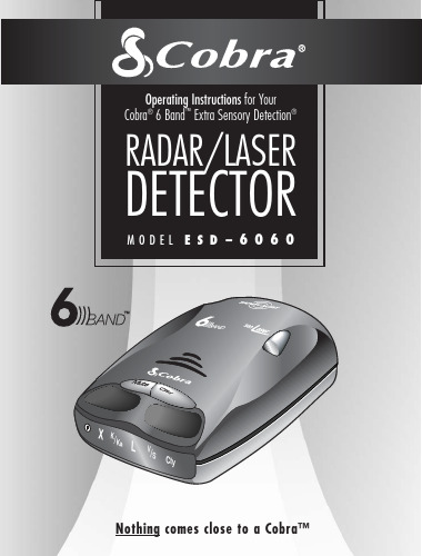
windshield bracket mountON-OFF/VOLUME controlindicatorpower CITY/HIGHWAY mode indicatorsindicator 12V DC POWER JACKAUTO MUTE of audio alerts.modes to reduce false alerts.for 360°the TONE alerts.12V DCTable of ContentsImportant information about...Federal Laws, Safety Alert,® Safe Driving,Security of Your Vehicle, Customer Support..................................................................................A1Installation ..................................................................................................................................2-4Operation–Getting Started ............................................................................................................5Operation–Settings ......................................................................................................................6-7Highway/City Mode ................................................................................................................6Muting an Alert ......................................................................................................................7Auto Mute Mode ....................................................................................................................7Detection ....................................................................................................................................8-11Signals Detected ....................................................................................................................8Audio Alerts ............................................................................................................................9Visual Display ........................................................................................................................9-10Instant-On Detection ................................................................................................................11Responding to Alerts ................................................................................................................11Understanding Radar and Laser ......................................................................................................12-13Maintenance and Service ..............................................................................................................14-15Limited 1-Year Warranty ................................................................................................................16Specifications ..............................................................................................................................17Optional Accessories ....................................................................................................................18Order Form ..................................................................................................................................19A1Important information about...Federal Laws Governing the Use of Radar DetectorsIt is not against federal law to receive radar transmissions with your Cobra ®radar detector. The Communications Act of 1924guarantees your right to receive radio transmissions on any frequency. Local laws that contravene this Act, while illegal, may be enforced by your local law enforcement officials until and unless they are prohibited from doing so by federal court action.Safety Alert ®Use of this product is not intended to, and does not, ensure that motorists or passengers will not be involved in traffic accidents. It is only intended to alert the motorist that an emergency vehicle equipped with a Cobra ®Safety Alert ®transmitter is within range as defined by that product.Please call local fire and police departments to learn if coverage exists in your area.Safe DrivingMotorists, as well as operators of emergency or service vehicles, are expected to exercise all due caution while using this product, and to obey all applicable traffic laws.Security of Your VehicleBefore leaving your vehicle, always remember to conceal your radar detector in order to reduce the possibility of break-in and theft.Customer SupportIn this user's manual, you should find all the information you need to install and operate your ESD-6060. If you require further assistance after reading throughthis manual, Cobra ®Electronics offers the following customer support services:Automated Help Desk is available 24 hours a day, 7 days a week at 773-889-3087.Customer Service Operators are available at 773-889-3087 Monday through Friday, 8:00 a.m. to 6:00 p.m. CST.Questions can be faxed to 773-622-2269.Automated Technical Assistance is available 24 hours, 7 days a week via e-mail at:*********************On-line answers to frequently asked questions can be found at: .WARNINGModifications or parts substitutions not approved by Cobra Electronics Corporation may violate FCC Rules and void your authority to operate this equipment.1O NWhere to Mount Your UnitYou will get optimum performance from your ESD-6060 if you mount it at a point approximately in the center of the vehicle,as low as possible on the front windshield without obstructing the unit's view of the road either to the front or rear. You can also mount it directly on the dashboard.1I N S gently push or pull on the bracket1I N SDashboard Mounting1.Place the detector on the dashboardto find a location where the unit hasa clear, level view of the road. Theangle can NOT be adjusted aftermounting.2.Remove the paper backing from oneside of the hook-and-loop fastener.2RT E DYou will hear 3 beeps and the Power Indicator will light up in the displayCtyO P E R AT I O N•S E T T I N G SMUTE buttonPress and releaseSignals DetectedThe tables on the following pages show you the types of signals your ESD-6060 will detect, as well as the voice and visual alerts it provides for each one.Audio AlertsA distinctly different alert tone is used for each type of signal detected. For X, K and Ka band radar signals, the tones will repeat faster as you approach the signal source.The repeat rate of the tones gives you usefulVisual DisplayAn indication of the type of signal®will During Safety Alert ®the letter ”V/S“ will appear.* your ESD-6060 provides LaserEye ®360°detection of these signalsResponding To AlertsInstant-On DetectionYour ESD-6060 is designed to detectinstant-on speed monitoring signals, whichcan suddenly appear at full strength.You should take appropriateaction immediately wheneveran alert is given.20-20™ and Ultra-Lyte™ are trademarks of LaserTechnology, Inc.ProLaser™ and ProLaser III™ are trademarks ofKustom Signals, Inc.Safety Alert®Traffic Warning System,VG-2 Alert®and LaserEye®are registered trademarks ofCobra Electronics Corporation.Interceptor VG-2™ is a trademark of TechniSonicIndustries LTD.U N D E R S TA N D I N G R A D A R&L A S E R Radar SpeedMonitoring SystemsThree band frequencies have been approved by the Federal Communications Commission (FCC) for use by speed monitoring radar equipment:X band 10.525 GHzK band24.150 GHzKa band33.400-36.00 GHz Your ESD-6060 detects signals in all three radar bands.VG-2VG-2 is a "detector detector" that works by detecting low-level signals emitted by most radar detectors. Your ESD-6060 does not emit signals that can be detected by VG-2, but does detect VG-2 signals and will alert you when a device is in use near your vehicle.Safety Alert®Traffic Warning SystemFCC-approved SafetyAlert®transmitters emit microwave radar signals that indicate the presence of a safety-related concern. Depending on the frequency of the signal emitted, it can indicate a speeding emergency vehicle or train, or a stationary road hazard.Because these microwave signals are within the K band frequency, most conventional radar detectors will detect Safety Alert®signals as standard K band radar. Your ESD-6060, however, is designed to differentiate between standard K band and Safety Alert®signals, and give separate alerts for each.Safety Alert®technology is relatively new. Safety Alert®transmitters can be found in limited numbers in all 50 states, but the number is growing. Depending on your location, you may not receive these alerts regularly and may often encounter emergency vehicles, trains, and road hazards without being alerted. As the number of transmitters increases, these alerts will become more common. When you receive such an alert, please watch for emergency vehicles ahead of you, on cross streets, and behind you. If you see an emergency vehicle approaching, please pull over to the right side of the road and allow it to pass.U N D E R S TA N D I N G R A D A R&L A S E RLIDAR (laser)The correct name for the technology that most people refer to as laser is actually LIDAR, which stands for Light Detection and Ranging. LIDAR operates much like radar. Its signal spreads out like a radar signal, though not as quickly. Unlike radar, LIDAR must have a clear line of sight to its target vehicle throughout the entire measurement interval. Obstructions such as sign posts, utility poles, tree branches, etc., will prevent valid speed measurement.M A I N T E N A N C E&S E R V I C E M A I N T E N A N C E&S E R V I C EIf you suspect that your unit requires service, please call 773-889-3087 BEFORE shipping it to Cobra.®This will ensure that you receive service as quickly as possible.If you are asked to send your unit to the Cobra®factory, please follow these steps: 1.Send the complete unit, includingpower cord. (It is not necessary toinclude the mounting bracket.)2. For warranty repair, enclose someform of proof-of-purchase, such as aphotocopy or carbon copy of a salesreceipt. If you send the originalreceipt, it cannot be returned.3. Enclose a typed or clearly writtendescription of the problem you arehaving with your unit, plus the nameand address where you want theunit returned.4. Pack the unit securely to preventdamage during transit. If possible,use the original packing materials.5. Ship prepaid and insured using atraceable carrier such as UnitedParcel Service (UPS), Federal Express,or first class mail with deliveryconfirmation. Ship to:Cobra Factory ServiceCobra Electronics Corporation6500 West Cortland StreetChicago, IL 60707 USA6. Please allow 3 to 4 weeks beforecontacting us about the status ofyour service. Call 773-889-3087for assistance.If your unit is under warranty, it will either be repaired or replaced upon receipt, depending on the model. If your unit is out of warranty, you will receive a letter informing you of the repair or replacement charge.Maintenance of YourRadar DetectorYour ESD-6060 is designed and built to give you years of trouble-free performance without the need for service. No routine maintenance is required.If your unit does not appear to be operating properly, please follow these troubleshooting steps:Make sure the power cord isproperly connected.Make sure the socket of your vehicle'scigarette lighter is clean and freeof corrosion.Make sure the power cord's cigarettelighter adapter is firmly seated in yourcigarette lighter.Check the power cord fuse. (Unscrewthe ribbed end cap of the cigarettelighter adapter and examine the fuse.If required, replace it with a 1-ampfuse only.)ServiceYou can receive technical assistance with your unit through one of our customer support services:Automated Help Desk is available 24 hours a day, 7 days a week at773-889-3087.Customer Service Operators are available at 773-889-3087Monday through Friday, 8:00 a.m. to 6:00 p.m. CST. Questions can be faxed to773-622-2269.Automated Technical Assistanceis available 24 hours, 7 days a week viae-mailat:********************* On-line answers to frequently asked questions can be found at: .17WA R R A N T Y16COBRA ELECTRONICS CORPORATIONwarrants that its Cobra ®6 Band™ Radar/Laser Detectors, and the component parts thereof, will be free of defects in workmanship and materials for period of one (1) year from the date of first consumer purchase. This warranty may be enforced by the first consumer purchaser, provided that the product is utilized within the U.S.A.Cobra ®will, without charge, repair or replace, at its option, defective 6 Band™Radar/Laser Detectors,products or component parts upon delivery to the Cobra ®Factory Service Department, accompanied by proof of the date of first consumer purchase,such as a duplicated copy of a sales receipt.You must pay any initial shipping charges required to ship the product for warranty service, but the return charges will be at Cobra's expense, if the product is repaired or replaced under warranty.This warranty gives you specific rights, and you may also have other rights which vary from state to state.Exclusions: This limited warranty does not apply;1) to any product damaged by accident; 2) in the event of misuse or abuse of the product or as a result of unauthorized alterations or repairs; 3) if the serial number has been altered,defaced or removed; 4) if the owner of the product resides outside the U.S.A. All implied warranties, including warranties of merchantability and fitness for a particular purpose are limited in duration to the length of this warranty.Cobra ®shall not be liable for any incidental, consequential or other damages; including,without limitation, damages resulting from loss of use or cost of installation.Some states do not allow limitations on how long an implied warranty lasts and/or do not allow the exclusion or limitation of incidental or consequential damages, so the above limitations may not apply to you.Cobra Electronics Corporation6500 West Cortland Street, Chicago, Illinois 60707S P E C I F I C AT I O N SThis radar detector is covered by one or more of the following U.S. patents:5,497,148; 5,594,432; 5,612,685; 6,078,279; 6,094,148. Additional patents may be listed inside the product or pending.10O R D E R F O R M19For credit card orders fill out order form and fax to: 773.622.2269or call 773.889.3087(Press 1 from the main menu)8:00 am - 6:00 pm, M-F, CST.Make check or money order payable to:Cobra Electronics6500 West Cortland Street Chicago, IL 60707 USA Attn: Accessories Dept.To order online,please visit our website at: and click “shop Cobra ®”Please print clearlyNameAddress (No P .O. Box)City StateZipTelephone ( )Credit Card No.Exp. DateCircle One: Visa MasterCard Discover Customer SignatureAllow 2-3 weeks for delivery. Offer valid in Continental U.S. only.O P T I O N A L A C C E S S O R I E S You can find these fine accessories at your local Cobra ®dealer. If you wish, you can order directly from Cobra.®To order by phone Call 773.889.3087(Press 1 from the main menu 8 a.m.-6 p.m. M-F CST. )To order by mail or fax Please fill out order form on next page, and mail/fax directly to Cobra.®To order onlineGo to and click on “shop Cobra.®”18Windshield Mounting Bracket Includes suction cups 545-139-N-001Curled 12V DC Power Cord Includes plug and fuse420-026-N-001Straight 12V DC Power Cord Includes plug and fuse Dual Port Power Adapter Includes adjustable plug (upto 90˚)and fuse CLP-2BPrinted in Korea Part No. 480-014-P©2002 Cobra Electronics Corporation6500 West Cortland StreetChicago, IL 60707 USA The Cobra®line of quality products includes:CB radiosmicroTALK®radiosRadar/Laser DetectorsSafety Alert®Traffic Warning SystemsAccessoriesHighGear™ AccessoriesFor more information orto order any of our products,please visit our website:Click “shop Cobra®”Nothing comes close to a Cobra™。
上海协堡电子 激光测距模块SLDM-C30 C60产品说明书
上海协堡电子有限公司ShangHai ShinePoin Electronics CO.,LTD.地址:上海市闵行区新骏环路115号寰启商务大厦1幢906室TEL:021-********FAX*************上海协堡电子有限公司ShangHai ShinePoin Electronics CO.,LTD.TEL*************FAX*************地址:上海市闵行区新骏环路115号寰启商务大厦1幢906室SLDM-C30/C60激光测距模块产品说明书(中文版)C目录第一章综述....................................................................................................................................1.1 产品简介............................................................................................................................. 第二章工作原理..............................................................................................................................2.1 原理简介............................................................................................................................. 第三章尺寸结构..............................................................................................................................3.1 外形图................................................................................................................................. 第四章技术数据..............................................................................................................................4.1 数据一览表......................................................................................................................... 第五章端口与通讯协议..................................................................................................................5.1 端口一览表......................................................................................................................... 第六章使用方法及步骤..................................................................................................................6.1 使用方法及步骤................................................................................................................. 第七章应用市场..............................................................................................................................7.1 案例场景............................................................................................................................. 第八章应用注意事项......................................................................................................................8.1注意事项.............................................................................................................................. 第九章警告与售后..........................................................................................................................9.1 注意与警告.........................................................................................................................9.2 售后服务............................................................................................................................. 第十章系统拓展与开发..................................................................................................................10.1 说明 ..................................................................................................................................10.2 联系我们...........................................................................................................................第一章综述1.1 产品简介SLDM-C30/C60激光测距模块是新一代测距传感装置,产品集功能强大、性能稳定可靠、安装使用方便、应用范围广等诸多优点于一体,是一种性能优良的经济型实时距离监测产品。
深达威激光测距仪50米 说明书米

激光测距仪带速度测量功能的SNDWAYSW-600A,SW-1000A,SW-1500A具有距离、速度、坡度和高度测量功能的多功能设备操作说明该产品的设计符合标准:GB/T14267-2009广东制造,货号:00000950安全说明使用前仔细阅读安全要求和操作说明在使用该设备之前,请阅读所有的安全和操作说明。
任何未在这些说明中描述的措施都可能导致设备发生故障,影响测量的准确性或对用户或第三方造成伤害。
请勿自行打开或修理该装置。
严禁对激光发射器的功能做任何修改或调整。
妥善存放设备,不要让儿童接触到它,避免未经授权的人使用。
切勿将激光发射器对准自己或旁人,对准你身体的任何部位或任何高度反射的物体。
该设备的电磁辐射会对其他电子设备造成干扰。
不要在飞机上或医疗设备附近使用本装置。
不要在爆炸性或易燃性环境中使用本设备。
不要将废旧电池和无法使用的电器与家庭垃圾一起处理。
请按照现行法律和关于处理此类设备的规定来处理设备。
如果您在使用过程中遇到任何问题或疑问,请立即联系您的SNDWAY官方代表,我们将尽快帮助您解决问题。
感谢你购买SNDWAY手持式激光测距仪!带倾斜测量功能的SNDWAY多功能激光测距仪是一款集双筒望远镜和激光测距仪功能于一体的便携式激光倾斜测距仪。
主要应用。
•对于物体的详细检查,测量静态物体或低速移动且在可视范围内的物体。
该仪器的特点是测量精度高,测量速度快,可检测参数的可视化。
经济性:提供自动断电和低耗电。
•多功能激光测距仪结合了最新技术,可同时显示物体的距离和倾角。
在确定与物体的距离时,它可以显示到目标点的线路与地面的角度(仰角定义为正,俯角定义为负),相对高度和可见地平线的范围。
激光发射器的功率足够低,对人眼来说很安全。
它能够测量任何物体的范围,其体积小、重量轻,便于携带。
它由一个可充电的锂离子电池供电。
测距仪广泛用于电力设施(复杂的测量和扫描功能可以方便地检查远处的物体,如电力线和电线杆)、高速铁路、公用事业、林业设计、建筑、互联网通信设计、通信线路的检查和维修等,在开放的乡村和高尔夫、狩猎和野营旅行中使用。
PD-I激光测距仪作业指导书
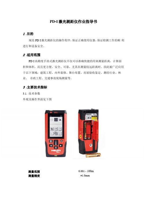
PD-I激光测距仪作业指导书1.目的规范PD-I激光测距仪的操作程序,保证正确使用仪器,保证检测工作的顺利进行和设备安全。
2.适用范围PD-I高精度手持式激光测距仪不仅可以准确快捷的用来测量距离,计算面积和体积,而且更方便、安全、可靠,尤其在测量较远距离时。
因此被广泛应用于以下领域:建筑工程、内外装修、舞台布置、房屋验收鉴定、测绘行业、林业、市政工程、交通事故现场测量等。
3.主要技术指标3.1.技术参数外观及操作界面见下图0.001 - 100m测量范围测量精度±1.0mm3.2.性能特点4.操作规程4.1.主要功能键4.1.1开关机启动:短暂按启动键。
在按动下个按键前,电池的显示会一直显示在显示屏上的。
关闭:按住关闭键直到仪器关闭。
为了延长电池的使用寿命,在3分钟内未触摸任何键盘时,激光将会自动关闭。
6分钟后仪器将会自动关闭。
4.1.2清除键使用清除键回到上一指令。
在测量面积或体积时,可以用清除键清除单个测量结果,重新进行测量。
4.1.3照明按住照明键,显示屏上的照明会开启或关闭。
在关闭仪器时,灯也会关闭。
4.1.4测量基准边在固定挡板打开时,仪器能自动识别测量基准边,并设置测量基准边以使得到正确的测量值。
测量基准边的标准设置是后沿。
按测量基准边键,可将测量基准边一次性地设置为从这个边出发的测量。
在测量后测量基准边会自动还原为以后沿为基准的设置。
也可以将测量基准边常设为前沿,较长时间按测量基准边-键{A,8}来完成此设置。
较长时间按测量基准边-键{A,8},将测量基准边返回到后沿。
4.2.测量4.2.1单个距离测量按DIST键开启激光。
再按此键进行测量。
测量结果将显示在显示屏上。
4.2.2最大/最小值测量这个功能可以提供从某一点出发来进行的最大或最小值的测量。
用于确定到墙角的距离(最大值)或垂直距离(最小值)等用法。
按住DIST键,直到听到峰鸣声。
缓慢地在目标周围大范围的移动激光,例如:房间的一角。
喜利得激光测量产品介绍

19
PD 28手持激光测距仪
数据处理 数据存储
储存位置
可存储1000个数据
1- 按 “=“ 开始存储 2- 键入测量编号来确定存储位置
测量编号 测量代号 测量类别
420: 10.313 m 728 313
数据传输至电脑
20
PD 28手持激光测距仪 技术数据
25
主要应用领域
PML 32也是中等距离内装的理想工具
贴砖 门窗
铺地板
吊顶
厨柜
26
PML 32的特点和为客户提供的好处
PML 32是一种自动找水平仪器,可以投射水平或垂直线,以及二者的组合线 (一 个垂直,一个水平) 自动水平 快速高效阻尼磁摆系统 (摆锤静止时间< 3sec) 稳定的水平 和垂直线 II级激光 单人操作 安装简便… …无需划线 安全,无需特殊安全保护措施 省时省钱 快速安装 / 准确无误 快速安装
22
PML 32能做什么?
PML 32是一种自动找平工具,可以投射水平或垂直线,以及二者的组合线 (同时 投射垂直和水平)
水平线
水平和垂直线
垂直线
23
喜利得 PML 32是一种自动找水平的激光定线工具 它可以投射垂直线和/或水平直线 多功能按钮 摆锤锁定按钮 保护摆锤 On/Off,垂直,水平
计算
计算面积、体积和周长 (例如:电缆长度,、需油漆
的面积和混凝土浇筑量
…)
4
测量误差导致的返工成本很高 所以需要许多的测量去确认所建筑的尺寸是否符合设计/计划 确定门开孔的大小是否符合 要求 (尺寸和是否正方)
优势
快、省时省力、简单、减少 错误、避免损失
日本宾得PEN报价湖北一级代理品牌

创威测绘五大强势品牌湖北省一级金牌代理商宾得在日本是测绘界的巨头,它的R-202N及R-300X系列全站仪被广泛应用在铁路、公路、隧道水利、水电、市政,国土测量等一些工程项目当中。
它率先研发出免棱镜激光全站仪,给我们广大用户带来了极大的方便;它的图形显示功能让我们看图就可以检查出现问题。
在价格方面,大大低于同级别进口全站,实在是全站中之极品,购买之最佳选择。
湖北总代理、物流中心、维修中心本公司是科力达在湖北省唯一的批发兼零售的单位,同时也是科力达定在武汉市的维修服务中心。
我们的价格是湖北省最低的,我们的服务是全国最好的,选择科力达的仪器,相信创威的实力。
在今年创威测绘很荣幸获得了科力达2007年度销售金奖和功勋奖,这也很大的激励了我们要进一步做好科力达仪器的销售工作和售后的服务工作。
科力达今年推出的KTS-442R免棱镜全站仪,它的免棱镜测程达到了200米。
加上它的自带道路设计软件为我们的道路放样带来了很大的帮助,今年这款仪器正在火爆抢购中。
华中区五省总代理2007年武汉洪山创威科技测绘中心与德国喜利得公司签定了华中地区总代理的协议。
在湖北、湖南、江西等省创威测绘是喜利得激光测距类仪器的源头。
喜利得公司除了为每一台测距仪提供德国原厂的品质保证书外,还对每一台测距仪提供国家检测部门出具的权威鉴定证书,并对测距产品提供长达3年的全免费保修服务,这些服务是在国内销售测距产品的厂家中绝无仅有的。
湖北省一级代理商中国华测是一家集国产GPS研发、生产于一体的高新技术产业集团公司,汇集了一批GPS领域的顶尖技术人才,拥有国内最具实力的GPS研发团队,在技术上不断自主创新,并已申请了多项专利。
公司生产的GPS产品贴近用户、性能稳定,获得了广大用户的好评。
中国华测在2006年已经与创威测绘达成了湖北省独家代理的协议,去年卖得最好的X90天骄系列RTK动态1+1+1的GPS为了服务更多的用户,在今年价格也做了进一步的下调。
TF02-Pro-W-485 用户手册说明书
TF02-Pro-W-485用户手册尊敬的用户:您好,感谢您选择北醒的产品。
为让产品的使用体验更好,我们特制定此用户手册,以帮助您更加便捷地使用产品。
本用户手册包括TF02-Pro-W-485激光雷达测距模组的介绍、使用和维护等相关内容,涵盖常见情况下的使用说明及问题处理措施。
请在使用前仔细阅读本手册,谨记注意事项,避免危险,并在使用过程中,严格遵守手册内所述步骤执行。
如果您在使用过程中遇到了无法解决的问题,欢迎您随时联系北醒工作人员协助解决。
联系方式官网地址:联系电话:400 880 9610咨询技术问题,请联系:********************咨询销售事宜或索取介绍资料,请联系:***************公司总部地址北醒(北京)光子科技有限公司北京市海淀区创业路六号自主创新大厦3层3030版权声明本文档版权归©北醒公司所有,未经北醒公司的官方书面许可,请勿改变文档中的内容描述,以及对文档进行修改、删减或翻译。
免责声明我们的产品还在不断改进和更新,因此TF02-Pro-W-485的规格参数可能会发生变化,请以官网上的最新版本为准。
1概览 (1)1.1产品参数 (1)1.2维护与清洁 (2)1.3外观与结构 (2)1.4设备存储 (4)2物理接口 (5)2.1线序说明 (5)2.2电气特性 (5)3除尘刷工作说明 (6)4通信协议与数据格式 (7)4.1RS-485通信协议 (7)4.2Modbus协议支持 (7)4.2.1数据获取指令说明 (7)4.2.2功能码说明 (7)4.2.3可访问寄存器地址 (8)4.3常用指令 (9)4.4配置示例 (10)1概览TF02-Pro-W-485是一款基于TF02-Pro-W升级的单点测距激光雷达,基于ToF(飞行时间)原理,具有更高性能,在通讯接口、输入电压、反接保护等方面做了优化升级,适应工业场景需求。
1.1产品参数表1-1 TF02-Pro-W-485产品参数列表提示①准确度、距离分辨率、重复精度等均在漫反射白板(90%反射率)条件下测得。
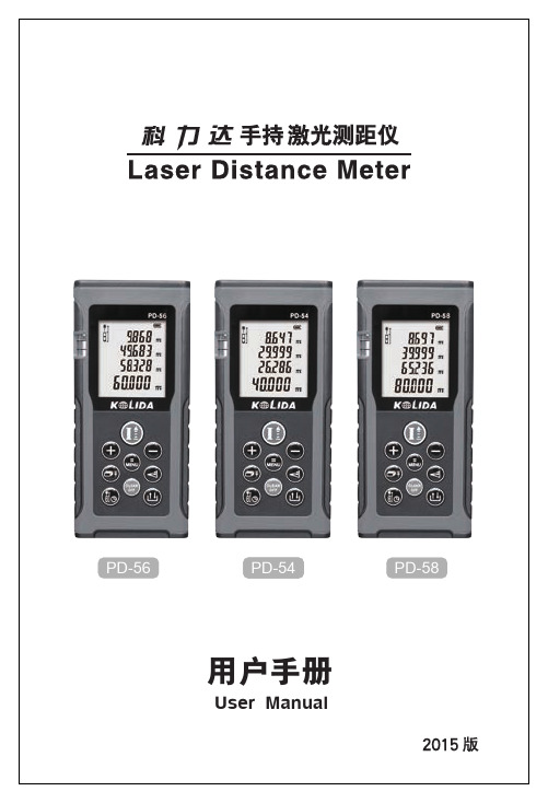
科力达PD-545658手持激光测距仪2015版用户手册
自品牌诞生以来,科力达就以做中国最优秀的测绘仪器供 应商为己任,尊重、团结、创新、活泼的文化理念造就了 一支充满朝气、能征善战的精英团队。目前,集技术、质 量、产能、成本等各方面优势于一身的科力达,正以坚定 的步伐,迈向国际市场,奔向更加美好的未来!
PD-56
PD-564
PD-58
用户手册
User Manual
科
力
科力达,以“创造测绘价值”为目标,以“做中国最优秀 的测绘仪器供应商”为己任,持续为广大用户提供最具性 价比的仪器,这是科力达的使命,也是科力达的实际行动。
达
公 司 简 介
科力达生产基地拥有国际先进水平的生产设备,严格的 品质控制,完善的管理流程,已成为国内行业最大产业群。 主要产品包括:三维激光扫描仪、航测无人机、GPS、 全站仪、经纬仪、水准仪、手持激光测距仪、投线仪、垂 准仪、测深仪、反射棱镜、塔尺、花杆、脚架等优质测绘 器材。是国内极少数熟练掌握绝对编码技术、双轴补偿、 免棱镜测距、Windows全站仪、数字水光测距仪这一新 兴领域,科力达更是未雨绸缪,从产品研发、生产、销售, 到产品应用、售后服务,均达到了行业内一流水平。
在研发上,科力达GNSS产品融入了最新的卫星导航技术, 精度更高,性能更稳定。科力达GNSS产品系列化的特点, 可根据用户不同的项目和工程精度需求,为客户打造高性 价比的产品解决方案。
凭借过硬的产品质量和出色的品牌战略,科力达成为行 业内发展最快的明星企业,仅几年时间就跻身国内最主流 品牌,目前经销商达400余家,各地物流中心和维修中心超 过40家,销售及服务网点覆盖全国、辐射全球,产品远销世 界50多个国家和地区。科力达的中国,世界的科力达。
爱华AWA6228+型多功能声级计使用说明书

ACOUSTICS & VIBRATION MEASURING INSTRUMENTS
+
AWA6228 型 多功能声级计(噪声分析仪)
爱华 使用说明书
杭州爱华仪器有限公司
HANGZHOU AIHUA INSTRUMENTS CO., LTD.
2018.1.5
更改记录及版本说明
版本 时间
“SMS”,RS232和蓝牙接口。
型式批准证书
型式批准证书号:2016S593-33
注意事项
1、第一次使用仪器前,请仔细阅读该说明书。 2、测试传声器膜片破损不在保修范围之内。 3、其它因使用不当造成的损坏不在保修范围之内。 4、电池应选用高性能碱性电池。不使用时,请将电池取出,以
免电池漏液造成仪器损坏。电池不在保修围范围内。
7.4.4 GB 12523-2011 建筑施工场界环境噪声排放标准.......... 38 7.4.5 GB 12525-1990 铁路边界噪声限值及测量方法.............. 38 7.5 模板选择........................................................................................38 7.5.1 模板查看.............................................................................39 7.5.2 模板的保存、删除及选用................................................. 39 8 仪器校准...................................................................................................40 8.1 声校准............................................................................................40 8.1.1 采用AWA6221A校准器进行声校准................................. 44 8.1.2 用活塞发声器进行校准..................................................... 44 8.1.3 采用AWA6223F校准器进行声校准.................................. 45 8.2 手动输入传声器灵敏度级............................................................ 45 8.3 校准记录查看................................................................................45 8.4 TEDS...............................................................................................46 9 GPS 模块.................................................................................................. 47 9.1 GPS测两点距离............................................................................. 48 9.2 GPS校准时钟................................................................................. 49 9.3 GPS定位测量................................................................................. 50 10 测量范围及本机噪声.............................................................................50 11 过载指示.................................................................................................52 附录一:装箱清单(标准配置)............................................................... 53 附录一 装箱清单(续,可选配置)......................................................... 54 附录二 指向性响应.....................................................................................55 附录二 指向性响应(续).............................................................................. 56 附录三 自由场响应.....................................................................................57 附录四 延伸电缆的影响.............................................................................59 附录五 滤波器衰减特性.............................................................................60
- 1、下载文档前请自行甄别文档内容的完整性,平台不提供额外的编辑、内容补充、找答案等附加服务。
- 2、"仅部分预览"的文档,不可在线预览部分如存在完整性等问题,可反馈申请退款(可完整预览的文档不适用该条件!)。
- 3、如文档侵犯您的权益,请联系客服反馈,我们会尽快为您处理(人工客服工作时间:9:00-18:30)。
• (1) 单勾股测量 • 按 键进入“单勾股测量”界面,左侧显示图标 • 瞄准A点,按 键测量斜距OA • 仪器水平,按 键测量平距OB。
• 单勾股测量案例 • 辅助显示区——三角形斜边,水平边值 • 主显示区——高差x的值
• (2) 双勾股测量 • 按 键进入“双勾股测量”界面,左侧显示图标 • 瞄准A点,按 键测量斜距OA • 仪器水平,按 键测量平距OB • 瞄准C点,按 键测量斜距OC
• 双勾股测量案例 • 辅助显示区——三角形斜边,水平边,斜边值 • 主显示区——高差x的值
• (3) 组合勾股测量
•按
键进入“组合勾股测量”界面,左侧显示图
标
• 瞄准A点,按 键测量斜距OA
• 瞄准B点,按 键测量斜距OB
• 仪器水平,按 键测量平距OC
• 组合勾股测量案例 • 辅助显示区——三角形斜边,斜边,水平边值 • 主显示区——高差x的值
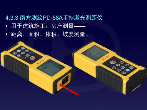
4.3.3 南方测绘PD-58A手持激光测距仪 • 用于建筑施工、房产测量—— • 距离,面积,体积,坡度测量。
• PD-58A正面与背面
• 电源——4×1.5V/7号AAA电池
• 与南方NTS全站仪通用的NF10反射板
• PD-58A技术参数 • ① 激光最大发射功率:<1mW • ② 激光:2级红色激光,波长635nm • ③ 测量误差:80m内,±1.5mm • ④ 测程:0.05~80m,>80m应使用NF10反射板 • ⑤ 倾斜传感器倾角测量范围±45o,误差±0.3o • ⑥ 电源:4×1.5V 7号AAA电池测量20000次。
• 6) 倾斜、平距与距离放样测量 • 内置倾斜传感器测量激光束竖直角 • 范围——±45o或±100%,误差——±0.3o或0.5% • 倾角单位——十进制度o或%,菜单模式MENU2设置 • (1) 倾斜测量 • 按 键启动倾斜传感器,屏幕顶部显示图标 • 辅助显示区第一行——实时显示仪器底边当前倾角 • 按 键测量
• 按 键确定当前数字位修改,闪烁数字自动左移一位
• 完成a放样值的修改后,按 键保存
• 闪烁数字自动下移至b放样值的最末一位数字。
• 仪器自动选择当前放样值——
• 最接近实测距离的n×a+m×b数值
• n,m——正整数。
• 放样测量案例 • 主显示区值=实测距离一当前放样值
• 7) 间接测量 • 按 键进入间接测量模式 • 通过测量2~3个距离值计算—— • 另一个高差,水平方向距离,面积 • 连续按 键可使测量功能按 • “单勾股测量→双勾股测量→组合勾股测量→ • 三角形测量→梯形测量1→梯形测量2”顺序循环切换
• 4) 设置测距基准边 • 按 键切换测距基准点——后端/前端 • 打开延长板,测距基准点自动设置为延长板尾端。
• 按住 键2s,进入菜单模式,将MENU6页设置为“ON” • 启动三角架测量,测距基准三脚架连接螺丝接口中心。
• 5) 菜单模式 • 按住 键2s后松开,进入菜单模式MENU1页 • 继续按 键可使MENU页号 • 按1→2→3→……→7→8顺序循环切换 • 按 键为向前翻页当前MENU页的设置内容 • 按 键为向后翻页当前MENU页的设置内容 • 再按住 键2s——保存菜单模式设置内容并退出 • 按 键——不保存菜单模式设置内容并退出 。
• 2) 距离测量 • (1) 单次距离测量 • 指示激光关闭时,按 键为打开指示激光 • 将指示激光对准目标,再按 键测距 • 屏幕主显示区——基准边至目标的距离值 • 并关闭指示激光 • 指示激光已开时,按 键为关闭指示激光 • 正在测距时,按 键为停止测距并关闭指示激光。
• (2) 延迟测量 • 已发射指示激光时,按住 键2s后松开 • 启动延迟测量功能,使指示激光准确对准目标 • 系统设置的固定延时时间为5s • 按 键一次为增加5s延时时间,最大为60s • 或按 键一次为减少5s延时时间,最小为0s • 设置的延时时间只对本次延迟测量有效 • 开始测距前的最后5s伴有蜂鸣声。
• (2) 平距测量 • 按 键进入平距测量模式,显示图标 • 辅助显示区第一行——实时显示仪器底边当前倾角 • 按 键测量
• (3) 放样测量
•按
键进入放样测量模式,显示图标
• 辅助显示区1,2行——a,b放样值
• a放样值的最末一位数字自动闪烁
• 按 键——闪烁数字加1,按 键——闪烁数字减1
• (3) 最大/最小距离测量 • 按住 键2s后松开,仪器进入跟踪测距模式 • 缓慢地在目标周围大范围移动指示激光 • 屏幕主显示区距离值随激光光斑移动实时变化 • 辅助显示区及时更新最小,最大距离值 • 再次按 键为停止测量。
• 3) 面积/体积测量 • 按 键进入面积测量模式 • 瞄准矩形的一条边,按 键测量 • 瞄准矩形的另一条相邻边,按 键测量 • 主显示区——面积,辅助显示区——2个距离值。
• 顶部显示图标
• 对准梯形上底边,按 键测量
• 对准梯形下底边,按 键测量
• 对准梯形高,按 键测量
• 主显示区——梯形斜边值。
• 按住 键2s • 辅助显示区——梯形斜边与高的夹角 • 主显示区——梯形面积
• (6) 梯形测量2
•按
键进入“梯形测量2”界面
• 1) 开/关机 • 按 键开机并发射指示激光,自动进入测距模式 • 开机状态,按住 键2s关机。 • 30s内无按键操作,仪器自动关闭指示激光 • 3min内无按键操作,仪器自动关机。 • 夜间测量时,可按住 键2s打开屏幕照明灯 • 再按住 键2s为关闭屏幕照明灯 • 也可在菜单模式下 • 将MUNE3设置为ON打开屏幕照明灯 • 或将MUNE3设置为OFF关闭屏幕照明灯。
• (4) 三角形测量
•按
键进入“三角形测量”界面
• 顶部显示图标
• 对准三角形的一条边,按 键测量
• 对准其邻边,按 键测量;对准对边,按 键测量
• 主显示区——三角形面积。
• 按住 键2s • 辅助显示区——三角形两邻边的夹角 • 主显示区——三角形周长
• (5) 梯形测量1
•按
键进入“梯形测量1ቤተ መጻሕፍቲ ባይዱ界面