rena操作手册
RENA清洗设备中文版说明书
RENA清洗设备中文版说明书RENA清洗设备中文版说明书仅操作部分6、操作6.1 开机6.1.1 步骤1:开机前准备第一步:打开药液供给侧的手动阀第二步:关闭所有后侧门第三步:关闭所有服务和维修窗口的盖板第四步:解锁所有急停按钮6.1.2步骤2:给机器上电第一步:将机器的主开关打到ON的状态此时机器有电第二步:移走UPS电源的盖板第三步:将UPS的主开关打到ON的状态第四步:将主机的主开关打到ON的状态此时操作系统启动6.1.3步骤3:给CHILLER上电第一步:将CHILLER的主开关打到ON的状态此时CHILLER启动6.1.4步骤4:登录Windows第一步:选择Operator用户第二步:输入Operator密码,点击确定6.1.5步骤5:启动应用软件6.1.5.1 启动SPS软件第一步:双击WINLC RTXSPS软件启动SPS软件开始自动运行,直到ON和RUN显示为绿色第二步:将WINLC RTX最小化6.1.5.2 启动Server第一步:双击Server第二步:点击Open Project第三步:选择Project Path第四步:点击[+]第五步:点击[Configuration]第六步:点击OK第七步:点击RUN第八步:点击Start Tag Provider第九步:最小化服务器程序6.1.5.3 启动用户界面第一步:双击[Client]6.1.6步骤6:用户登入第一步:登入Process6.1.7步骤7:控制系统上电第一步:按动ON按钮6.2 工艺初始化准备第一步:登入Service第二步:了解所有报警信息第三步:将机器打到Manual状态第四步:对所有的功能单元下载Recipe第五步:冷却系统补液第六步:清洗槽补液第七步:所有dosage tanks补液第八步:所有Pump tanks补液此时机器用于工艺已准备好6.3 自动生产第一步:登入Operator用户第二步:确认所有的功能单元都处在Ready状态第三步:点击Start production6.3.3 停止自动生产6.3.3.1 停止预定的自动生产第一步:点击Scheduled stop弹出一个窗口第二步:点击YES仍在机器内的硅片跑出后停止6.3.3.2 停止未预定的自动生产第一步:点击Unscheduled stop弹出一个窗口第二步:点击YES仍在机器内的硅片将过刻6.3.3.3 停止自动生产—关闭步骤1:停止预定的自动生产第一步:点击Scheduled stop第二步:点击YES仍在机器内的硅片跑出后停止步骤2:点击Unscheduled time 6.3.4 手动补液6.3.4.1 工艺槽补液第一步:点击Process bath第二步:点击欲加液的dosage tank. 第三步:点击dosage第四步:输入欲加液的体积第五步:点击Start manual dosage 补液开始停止补液第一步:点击Stop manual dosage 补液停止6.3.4.2 碱槽补液与以上相似6.3.4.3 酸槽补液与以上相似6.3.5 滚轮操作6.3.5.1 停止滚轮第一步:点击Drives break滚轮停止转动6.3.5.2 启动滚轮第一步:点击Drives continue滚轮开始转动6.3.6 机器保护门的操作6.3.6.1 解锁保护门第一步:点击Unlock pane保护门解锁6.3.6.2 锁保护门第一步:点击Lock pane保护门锁上6.3.7硅片计数器清零第一步:点击Reset wafer counter硅片计数器清零6.4 手动操作6.4.1 将机器打到Manual状态第一步:点击Manual第二步:等到所有功能单元都切换到Manual状态6.4.2 冷却系统补液第一步:将机器打到Manual状态第二步:点击Cooling System第三步:点击Manual functions第四步:点击Fill with City Water冷却系统开始补液中断冷却系统补液第五步:点击Stop正补液的冷却系统停止补液6.4.3 清洗槽补液第一步:将机器打到Manual状态第二步:点击欲加液的清洗槽第三步:点击Manual functions第四步:点击Fill with DI清洗槽开始补液6.4.4 dosage tank补液6.4.4.1 工艺槽dosage tank补液第一步:将机器打到Manual状态第二步:点击Process bath第三步:点击Manual functions第四步:点击欲加化学药品的Dosage T ank Fill dosage tank开始补液第五步:对所有的dosage tank重复第四步的操作中断补液第六步:点击Stop补液被中断6.4.4.2 碱槽的dosage tanks补液与以上相似6.4.4.3 酸槽的dosage tanks补液与以上相似6.4.5 Pump tanks 补液6.4.5.1 工艺槽Pump tanks 补液第一步:将机器打到Manual状态第二步:点击Process bath第三步:点击Manual functions第四步:对所有的dosage tanks补液第五步:点击Fill chemistryPump tank将按照recipe的设定补液中断补液第六步:点击Stop补液被中断6.4.5.2碱槽Pump tanks 补液与以上相似6.4.5.2酸槽Pump tanks 补液与以上相似6.4.6 Bath槽补液第一步:将机器打到Manual状态第二步:冷却系统补液第三步:所有清洗槽补液第四步:所有dosage tanks补液第五步:所有pump tanks补液第六步:点击InOxSide第七步:点击Start production Bath槽开始补液6.4.7 冷却系统排液第一步:将机器打到Manual状态第二步:点击Cooling system第三步:点击Manual functions第四步:点击Drain冷却系统开始排液中断排液第五步:点击Stop排液被中断6.4.8清洗槽排液与以上相似6.4.9 将Baths的药液排到pump tank 第一步:将机器打到Manual状态第二步:选择欲操作的功能单元第三步:点击Manual functions第四步:点击Drain bath to pump tankBath开始排液到Pump tank中断排液第五步:点击Stop排液被中断6.4.10 对baths and pump tank排液第一步:将机器打到Manual状态第二步:选择欲操作的功能单元第三步:点击Manual functions第四步:点击DrainBath和Pump tank将被排空6.4.11 对dosage tanks排液第一步:将机器打到Manual状态第二步:选择欲操作的功能单元第三步:点击Manual functions第四步:点击DrainBath和Pump tank将被排空第五步:点击欲操作的dosage tank的Drain dosage tank dosage tank的药液被排到pump tank.pump tank.的药业被排空中断排液第六步:点击Stop排液被中断6.4.12 换液Changing the bath第一步:将机器打到Manual状态第二步:选择欲操作的功能单元第三步:点击Manual functions第四步:点击Bath change6.4.13 启动自动清洗清洗周期和清洗时间由recipe的参数预设第一步:将机器打到Manual状态第二步:选择欲操作的功能单元第三步:点击Manual functions第四步:点击Clean开始清洗中断清洗第五步:点击Stop清洗被中断6.4.14 启动手动清洗6.4.14.1 工艺槽的手动清洗第一步:将机器打到Manual状态第二步:点击Process bath第三步:点击Manual functions第四步:点击Start manual rinseBath槽的排液阀门打开用水枪冲洗bath槽中断清洗第五步:点击StopBath槽的排液阀门关闭手动清洗被中断6.4.14.2 酸槽的手动清洗与以上相似6.4.15 停止手动清洗6.4.15.1 工艺槽的手动清洗第一步:将机器打到Manual状态第二步:点击Process bath第三步:点击Manual functions第四步:点击stop manual rinseBath槽的排液阀门关闭6.4.15.2酸槽的手动清洗与以上相似6.4.16 初始化第一步:将机器打到Manual状态第二步:选择欲操作的功能单元第三步:点击Init功能单元开始初始化中断初始化第四步:点击Stop初始化被中断6.4.17 dosage tanks的余量置零第一步:将机器打到Manual状态第二步:点击Process bath第三步:点击Manual functions第四步:点击Bath changeThe bath is changed.The rest volume dosage tank is reseted 6.4.18 检测第一步:登入Process用户第二步:打开检测单元的盖子第三步:将检测容器与检测软管连接第四步:关闭检测单元的盖子第五步:点击sampling按钮5秒第六步:打开检测单元的盖子第七步:取出检测容器第八步:锁上检测容器第九步:关闭检测单元的盖子第十步:登入Operator用户6.5 设置6.5.1 改变温度6.5.1.1 在生产过程中改变温度第一步:点击Inoxside第二步:点击Bath temperature第三步:改变温度值第四步:点击OK6.5.1.2 在Recipe里改温度第一步:点击Inoxside第二步:点击Process bath第三步:点击Recipe第四步:双击pump tank temperature or bath temperature的数值第五步:更改数值第六步:点击OK6.5.2 更改带速6.5.2.1在生产过程中改变速度第一步:点击Inoxside第二步:点击Speed setpoint第三步:改变速度值第四步:点击OK6.5.2.2在Recipe里改速度第一步:点击Inoxside第二步:点击Transport第三步:点击Recipe第四步:双击欲改变的数值第五步:更改数值第六步:点击OK6.5.3 设置第一次补液的比例第一步:点击Inoxside第二步:点击欲操作的功能单元第三步:点击Recipe第四步:双击Concentration for first fill'.的数值第五步:更改数值第六步:点击OK6.5.4 设置自动补液第一步:点击Inoxside第二步:点击欲操作的功能单元第三步:点击Recipe第四步:双击Dosage V olume'的数值第五步:更改数值第六步:点击OK6.5.5 设置自动清洗6.5.5.1设置清洗周期的编号第一步:点击Inoxside第二步:点击欲操作的功能单元第三步:点击Recipe第四步:双击Numbers of Cleaning Cycles'.的数值第五步:更改数值第六步:点击OK6.5.5.2设置清洗时间第一步:点击Inoxside第二步:点击欲操作的功能单元第三步:点击Recipe第四步:双击Cleaning time'.第五步:更改数值第六步:点击OK6.5.6设置流动时间第一步:点击Inoxside第二步:点击欲操作的功能单元第三步:点击Recipe第四步:双击Setpoint flow'第五步:更改数值第六步:点击OK6.5.7设置dryer第一步:点击Inoxside第二步:点击dryer第三步:点击Recipe第四步:双击要改变的参数第五步:更改数值第六步:点击OK6.6 关机6.6.1 步骤1:机器排液第一步:点击Scheduled stopNo new wafers are conveyed into the machine.The mode of the machine is? changed to 'Standby'.Processing of any wafers that are still in the? machine is carried out to the end. The baths are drained into the pump? tank.The mode of the machine is changed to? 'Manual'.6.6.2步骤2:结束工艺准备就绪第一步:登入Process用户第二步:所有的Pump tanks排液第三步:所有的Dosage tanks排液第四步:清洗所有的Dosage tanks第五步:清洗所有的Pump tanks第六步:将机器状态改为Off6.6.3步骤3:关闭控制电源第一步:在控制面板上点击Off按钮机器将不再能从界面上控制6.6.4步骤4:关机准备第一步:关闭所有的药液提供侧的手动阀6.6.5步骤5:关闭总电源第一步:将主开关打到Off状态6.7 急停按下后的开机6.7.1步骤1:开机准备第一步:处理急停原因第二步:解锁所有的急停按钮6.7.2步骤2:打开控制电源第一步:点击ON按钮6.7.3步骤3:启动准备就绪第一步:登入Service用户第二步:将机器打到manual状态第三步:了解所有的报警信息6.7.4步骤4:开始自动生产第一步:登入Operator用户第二步:确保所有的功能单元都处于Ready状态第三步:点击InOxside第四步:点击Start production该按钮键变绿状态显示变为InitBaths槽开始补液状态显示变为Auto机器开始生产The Semi E10状态改为Start production 6.8断电后的开机6.8.1断电断于10分钟的开机6.8.1.1步骤1:开机前准备第一步:重启电源6.8.1.2步骤2:打开控制电源第一步:按动ON按钮控制电源上电该按钮键显示为绿色6.8.1.3步骤3:启动准备就绪第一步:登入Service用户第二步:将机器打到manual状态第三步:了解所有的报警信息6.8.14步骤4:开始自动生产第一步:登入Operator用户第二步:确保所有的功能单元都处于Ready状态第三步:点击InOxside第四步:点击Start production该按钮键变绿状态显示变为InitBaths槽开始补液状态显示变为Auto机器开始生产The Semi E10状态改为Start production 6.8.2大于10分钟断电后的开机6.8.2.1步骤1:开机前准备第一步:重启电源6.8.2.2步骤2:打开控制电源第一步:按动ON按钮控制电源上电该按钮键显示为绿色6.8.2.3步骤3:windows登入第一步:点击operator第二步:输入密码Operator点击OK6.8.2.4步骤4:启动准备就绪第一步:登入Service用户第二步:将机器打到manual状态第三步:了解所有的报警信息第四步:对所有的功能单元下载Recipe第五步:冷却系统补液第六步:所有清洗槽补液第七步:所有的dosage tanks 补液第八步:所有的pump tanks 补液此时设备准备好6.8.2.5步骤5:开始自动生产第一步:登入Operator用户第二步:确保所有的功能单元都处于Ready状态第三步:点击InOxside第四步:点击Start production该按钮键变绿状态显示变为InitBaths槽开始补液状态显示变为Auto机器开始生产The Semi E10状态改为Start production。
RENA-intex培训
Acidic bath
Rinse3
Dryer
4
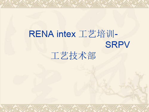
一.RENA设备:各槽作用
remove residual acid and assist to create Remove saw damage and crroeuagteh rwoaufgehr swuarffearce
surface
Acidic saw damage Rinsing
正常
阀门压缩气: 0.65±0.05Mpa
风刀压缩气: 0.6±0.05Mpa
冷却水: 进0.44±0.05Mpa,出为0Mpa,
温度〈20度。
纯水: 0.3-0.4Mpa
自来水: 0.2±0.05Mpa
化学品供应:在软件界面下,点击F10 查看各 Media
Supply 均正常供应(箭头均为绿色)
3)酸槽换液操作与碱槽大致相同,加完药液 后一定确认药液加入体积是否准确,每个槽 体相应界面上均有“first fill volmue”和 “actual fill volume”,比较下确认。若实际 加入量比设定值少,首先查找下原因,并采 用手动添加的模式,补入差值。
六.开关机操作
开始生产操作:登入用户名后检查配套动力项目是否
InTex设备操作指导书
版本号REVIEW 审核APPROVE 批准REV.版本号GENERAL WI 操作规程Reason(s) for Update 更新原因:新建立RENA设备操作规程ORIGINATOR 编制DOC.#: 文件号REV. EI-C-0020 00PAGE:页 1 OF 9部门签名日期1.目的规范InTex清洗设备的操作.2.范围适用于金保利((泉州)科技实业有限公司电池车间清洗工序3.参考文件主要材料;KOH,HCL HF,HNO3.RENA设备的操作说明书4.适用设备适用电池车间的RENA的清洗设备5.定义6.职责和权限6.1设备部负责该文件的制定和执行情况的监督。
6.2 制造部负责该文件的执行。
7.程序内容7.1准备工作.7.1.1 7.1.1检查设备的各项外围动力条件纯水、压缩空气,各槽排风压力等正常7.2 设备点检7.2.1 根据《RENA清洗机点检表》对设备进行点检,部分点检项目要在开机后~上料前 进行检查确认。
7.2.2 重要点检项目7.2.2.1 检查设备的压缩空气的压力要达到6KG.7.2.2.2 检查设备的滚轮运行良好,无异常现象。
7.2.2.3 检查设备管道无漏液的现象。
7.2.2.4 检查DRY 的管道没有堵塞。
7.3 设备操作7.3.1 开机程序7.3.1.1打开自来水,纯水,冷却水和压缩空气阀门。
GENERAL WI 操作规程RENA设备操作规程DOC.#: 文件号REVIEW审核APPROVE 批准 7.3.1.4 开始登陆程式,“Login”位于窗口的右上角,点击即可.GENERAL WI 操作规程ORIGINATOR 编制PAGE:页 2 OF 9签名日期 7.3.1.6 按按钮“Mode Auto ”在屏幕的右边切换为自动模式,在图表里的全部操作的单位的 地方“O ff ”的颜色变为“Auto ”绿色.7.3.1.3 打开设备前面的的显示器.RENA设备操作规程颜色全部为绿色。
RENA操作手册中文版更新
1. 一般规章1.1使用具有腐蚀性的化学品时需要具备足够的防护措施,建议使用抗腐蚀的盖板、衣服、鞋、手套和护目镜。
此外,需确保自己一旦发生事故的情况下,能找到适当的紧急喷淋冲洗设施。
1.2 决不在机器内单独工作。
1.3 不要打开或去除正在运行的设备盖板,因为其内部蒸汽为危险性的酸或碱。
2. RENA设备正常操作的要求2.1 化学供应和处理2.1.1 对于使用传感器准确测量化学品的流量,至少要求7L/min的流量,供应化学品的管路中不允许有一段一段的气泡。
对于使用化学槽处理,装载HF/ HNO3的刻蚀槽,其最大体积InTex为550L,InOxside为450L。
2.2 压缩空气2.2.1 对RENA InTex设备的Air Knifes规定的操作压力要求至少为4bar,Air Knifes不使用的情况下,压力需为6bar。
2.2.2 若Air Knifes的气压不足,硅片吹不干,进而容易导致alkaline bath清洗后产生棕色污点,因此造成产品品质不良。
2.2.3 若Air Knifes 2和Air Knifes 3的气压不足,可能硅片没有被正确的吹干,因此将需要另外的清洁处理程序。
注:当Air Knifes动作时请确认所有的阀门都打开。
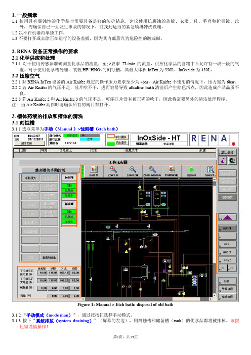
3. 槽体药液的排放和槽体的清洗3.1 刻蚀槽3.1.1 选取菜单为手动(Manual )>蚀刻槽(etch bath)Figure 1: Manual > Etch bath: disposal of old bath3.1.2 “手动模式(mode man)”,通过按按钮选择手动模式。
3.1.3 按下“系统排放(system draining)”(屏幕的左边),则刻蚀槽和储备槽(tank)的化学品都将被排掉。
该按钮需谨慎操作!3.1.4 等化学品排放过程完成后,屏幕上显示为“清空(Empty)”,为下面程序做好准备。
3.1.5清洗刻蚀槽和储液罐,按下“系统添加DI水(filling DI)”向储液罐添加DI水,待加满后,按下“由罐向槽填充药液(fill bath)”开启循环,循环一定时间后,按下“系统排放(system draining)”排空液体。
rena技术员培训-精选文档

DI water
1.3.2 InOxSIde操作系统主界面
KOH DI water
蚀刻槽 HF+HNO3+H2SO4+DI
HF
CDA
DI water
1.3.3 RENA主界面详细说明
程序内 的日期 和时间 模式、与PLC的 连接情况及登陆 的用户名
灯塔状 态
机器名称
目 的 :
a)去除硅片表面的磷硅玻璃;b)去掉硅片背面及
周边p-n结。
1.2.2 工作流程
Intex
上料台 制绒槽 吹 干 漂洗 1# 碱 洗
下料台
干 燥
漂洗 3#
酸 洗
漂洗 2#
InOxSide
上料台 刻蚀槽 漂洗 1# 碱 洗 漂洗 2#
下料台
干 燥
漂洗 3#
酸 洗
1.2.3 RENA一次清洗工艺
1.1.1 RENA整机
1.1.1 RENA整机
注:公司一般会根据需要在RENA前后加装上料台、下料台用来代替人工手工放片。 在下料台也会安装吸片装置,用以挑出损坏,破碎的片子。
6
1.1.2 冷却器
1.1.3 电控柜外部
1.1.4 电控柜内部
1.1.5 化学品输送及排风管道
1.1.6 气、水输送管道
KOH溶液,主要去除多孔硅和中和硅表面残余的酸。
反应如下:
Si+2KOH+H2O
K2SiO3+2H2
22
酸洗(HF)的目的及机理
酸洗槽(去PSG): 氢氟酸能够溶解二氧化硅是因为氢氟酸能与二氧化硅 作用生成易挥发的四氟化硅气体。
SiO 4HF SiF 2H O
2 4 2
Renaissance Series Emergency Care Stretcher 操作手册说明

Renaissance Series 1212 Emergency Care StretcherTable of Contents. . . . . . . . . . . . . . . . . . . . . . . . . . . . . . . . . . . . . . . . . . . . . . . . . . . . . . . . . . . . . . . . . . . . . Introduction2 . . . . . . . . . . . . . . . . . . . . . . . . . . . . . . . . . . . . . . . . . . . . . . . . . . . . . . . . . . . . . . . . . . . . Specifications2. . . . . . . . . . . . . . . . . . . . . . . . . . . . . . . . . . . . . . . . . . . . . . . . . Warning / Caution / Note Definition2 Operating Three–Sided Controls Base3. . . . . . . . . . . . . . . . . . . . . . . . . . . . . . . . . . . . . . . . . . . . . .. . . . . . . . . . . . . . . . . . . . . . . . . . . . . . . . . . . . . . . . . . . . . . . Operating Four–Sided Controls Base4. . . . . . . . . . . . . . . . . . . . . . . . . . . . . . . . . . . . . . . . . . . . . . . . . Raising And Lowering Litter Height5. . . . . . . . . . . . . . . . . . . . . . . . . . . . . . . . . . . Trendelenberg/Reverse Trendelenberg Positioning5. . . . . . . . . . . . . . . . . . . . . . . . . . . . . Operating Directional Steering Caster/5Th Wheel Options5. . . . . . . . . . . . . . . . . . . . . . . . . . . . . . . . . . . . . . . . . . . . . . . . . . . . . . . Applying The Brake System6 . . . . . . . . . . . . . . . . . . . . . . . . . . . . . . . . . . . . . . . . . . . . . . . . . . . . . . . . . . . . . . Using Push Handles6. . . . . . . . . . . . . . . . . . . . . . . . . . . . . . . . . . . . . . . . . . . . . . . . . Operating Fowler And Knee Gatch7 . . . . . . . . . . . . . . . . . . . . . . . . . . . . . . . . . . . . . . . . . . . . . . . . . . . . . . . . . . . . . . . . . . . Using Siderails8. . . . . . . . . . . . . . . . . . . . . . . . . . Operating Optional 2–Stage Permanently Attached I.V. Pole9. . . . . . . . . . . . . . . . . . . . . . . . . . . . . . . . . . . . . . . . . . . . . . . Operating Optional Tethered I.V. Pole9. . . . . . . . . . . . . . . . . . . . . . . . . . Operating Optional 3–Stage Permanently Attached I.V. Pole10. . . . . . . . . . . . . . . . . . . . . . . . . . . . . . . . . . Operating Optional Foot Extension/Defibrillator Tray10. . . . . . . . . . . . . . . . . . . . . . . . . . . . . . . . . . . . . . . . . Operating Optional X–Ray Cassette Holder11. . . . . . . . . . . . . . . . . . . . . . . . . . . . . . . . . . . . . . . . . . . . . . . . . . . Operating Optional Heel Stirrups12. . . . . . . . . . . . . . . . . . . . . . . . . . . . . . . . . . . . . . . . . . . . . . . Using Optional Head Board/Push Bar12 Preventative MaintenanceCleaning13 . . . . . . . . . . . . . . . . . . . . . . . . . . . . . . . . . . . . . . . . . . . . . . . . . . . . . . . . . . . . . . . . . . . . . . .. . . . . . . . . . . . . . . . . . . . . . . . . . . . . . . . . . . . . . . . . . . . . . . . . . . . . . . . . . . . . .Biannual Checklist13 Limited Warranty. . . . . . . . . . . . . . . . . . . . . . . . . . . . . . . . . . . . . . . . . . . . . . . . . . . . . .Obtaining Parts and Service14. . . . . . . . . . . . . . . . . . . . . . . . . . . . . . . . . . . . . . . . . . . . . . . . .Supplemental Warranty Coverage14 . . . . . . . . . . . . . . . . . . . . . . . . . . . . . . . . . . . . . . . . . . . . . . . . . . . . . . . . . . . .Return Authorization15. . . . . . . . . . . . . . . . . . . . . . . . . . . . . . . . . . . . . . . . . . . . . . . . . . . . . . . . . .Freight Damage Claims15IntroductionINTRODUCTIONThis manual is designed to assist you with the operation of the 1212 Emergency Care Stretcher. Read it thor-oughly before using the equipment or beginning any maintenance on it.SPECIFICATIONSWARNING / CAUTION / NOTE DEFINITIONThe words WARNING, CAUTION and NOTE carry special meanings and should be carefully reviewed.WARNINGThe personal safety of the patient or user may be involved. Disregarding this information could result in injury to the patient or user.CAUTIONThese instructions point out special procedures or precautions that must be followed to avoid damaging the equipment.NOTEThis provides special information to make maintenance easier or important instructions clearer.AAABBBCCCDEFOOT ENDAPump to raise litter.BDepress to lower head end.CDepress to lower foot end.DBrake and Steer functions (control end).EBrake and Steer functions (non –control end).AAAB BBCCC DDFOOT ENDABC APump to raise litter.BDepress to lower head end.CDepress to lower foot end.DBrake and Steer functions.RAISING AND LOWERING LITTER HEIGHTNOTEFor user convenience, there are two stretcher bases available: a ”three–sided” base with pump pedals and control pedals on both sides of the stretcher and on the foot or head end and a ”four–sided” base with pump pedals and control pedals on both sides and on both ends.CAUTIONBe sure to move any equipment that may be in the way before raising or lowering stretcher height.To raise the litter height, pump the foot pump pedal (A) repeatedly until desired height is achieved. (See il-lustration, page 3 for ”three–sided” bases or page 4 for ”four–sided” bases).To lower the litter height, depress pedal (B) to lower the head end and depress pedal (C) to lower the foot end of the stretcher. (See illustration, page 3 or page 4). The base may be equipped with optional variable descent controls. With variable descent controls, the farther you press down on the pedal, the faster the litter will lower.NOTEWhen lowering both ends of the stretcher simultaneously, activate both pedals (B) and (C) using the same foot.TRENDELENBERG/REVERSE TRENDELENBERG POSITIONINGNOTELitter height must be raised first in order to achieve a trend. or reverse trend. position.CAUTIONBe sure to remove any equipment that may be in the way before lowering stretcher.For Trendelenberg positioning (head down), depress pedal (B). (See illustration, page 3 or page 4).For Reverse Trendelenberg positioning (foot down), depress pedal (C). (See illustration, page 3 or page 4).NOTEThe higher the litter is before pedals (B) or (C) are activated, the greater the trend. or reverse trend. angle will be. (Maximum trend. angle is +18_. Maximum reverse trend. angle is –18_).OPERATING DIRECTIONAL STEERING CASTER/5TH WHEEL OPTIONSThe purpose of the steer wheel and 5th wheel options are to help guide the stretcher when transporting a patient along a straight line and also for pivoting at corners.NOTEStretchers cannot be equipped with both steering caster and fifth wheel options. The choice was made at the time the stretcher was purchased.Important: For proper ”tracking” of the steer caster or fifth wheel options, push the stretcher approximately 10 feet to allow the wheels to face the direction of travel before engaging the steer pedal. If this procedure is not followed, proper ”tracking” will not occur, causing difficulty with steering the stretcher.The steer wheel is located at the foot end of the stretcher on the patient’s left. The 5th wheel is located under-neath the center of the base assembly.To engage the steer wheel/5th wheel on a ”Dual Side Control” stretcher, push the right side of pedal (D) to the full down position. (See illustration page 3).To engage the steer wheel/5th wheel on a ”Dual End Control” stretcher, pull pedal (D) to the full up position. (See illustration page 4).APPLYING THE BRAKE SYSTEMNOTEFor user convenience, the Brake/Steer pedal is located on both ends of the stretcher on both ”three–sided”and ”four–sided” control stretchers.CAUTIONIf brakes do not hold properly, refer to your stretcher maintenance manual for ”Brake Adjustment”To engage the brakes on the non–control end of a ”three–sided” base stretcher, push fully down on the left side of pedal (E). (See illustration page 3).To engage the brakes on the control end of a ”three–sided” base stretcher and on both ends of a ”four–sided”base stretcher, push fully down on pedal (D). (See illustrations page 3 and 4).USING PUSH HANDLESCAUTIONThe push handles should always be used when transporting patients. Avoid using other parts of the stretcher as pushing devices or damage may occur.I.V. PolePush Handle Push HandleSiderailHead end push handles in the stored position.To use the push handles:Pivot the handles up and push down until they are locked into position.To store the push handles:Lift the handles up and pivot them down to store in the handle rests.OPERATING THE FOWLER/KNEE GATCHNOTEThere are two types of Fowler options: 1) crank operated, 2) pneumatic operated. The choice was made at the time the stretcher was purchased. A crank Knee Gatch is also optional.Crank Fowler/Crank Knee Gatch:Pneumatic Fowler:Turn crank handle (A) clockwise to raise Fowler, counterclockwise to lower.ABTurn crank handle (B) clockwiseto raise Knee Gatch, counter–clockwise to lower.Squeeze handle (A) for pneumatic assist in liftingthe Fowler to the desired height. Remove hand(s)from handle when desired height is achieved.To lower, squeeze handle (A) and push down untilFowler has reached desired height. Remove hand(s)from handle when desired height is achieved.CAUTIONIf pneumatic system appears to be difficult to op–erate, refer to the Stretcher Maintenance Manualfor ”Pneumatic Fowler Adjustment”.WARNINGKeep hands/fingers clear of area around Fowlerrelease handle and Fowler frame when lowering.ABInjury could result if care is not taken when loweringthe Fowler.USING SIDERAILSNOTERaising and lowering siderails is a two–handed operation. Use one hand to hold and position the siderail and the other hand to operate the siderail latch.WARNINGWhen lowering the siderail to the collapsed position, keep extremities of patients and staff away from the side-rail spindles.C BATo engage siderails: Pull up siderail (A) and raise to full up position so that latch (B) engages. (See illustra-tion).To disengage siderails: Pull up on latch (B) and guide siderail to the full down position.There is an optional siderail release latch (C) at the head end of the stretcher. Pull up on the latch and guide the siderail down.CAUTIONDo not allow siderail to lower on its own.OPERATING OPTIONAL 3–STAGE PERMANENTLY ATTACHED I.V. POLENOTEAn optional 3–stage permanently attached I.V. Pole may have beeninstalled at either the head, foot or both ends of the stretcher. Thechoice was made at the time the stretcher was purchased.To use the 3–stage permanently attached I.V. pole:1. Liftand pivot the pole from the storage position and push downuntil it is locked into receptacle (A).2. T o raise the height of the pole, turn the lock actuator (B) counter–clockwise and pull up on the bottom telescoping portion (C) of the poleto raise it to the desired height.3. Turn the lock actuator (B) clockwise to lock the bottom telescopingportion in place.4. For a higher I.V. pole, push up on the top section of grip (D) and pullup on section (E). Release the top section of grip (D) when the desiredheight is achieved.5. Rotate the I.V. hangers (F) to desired position and hang I.V. bags.CAUTIONThe weight of the I.V. bags should not exceed 40 pounds. OPERATING OPTIONAL 2–STAGE PERMANENTLYATTACHED I.V. POLENOTEAn optional 2–stage permanently attached I.V. Pole may have beeninstalled at either the head, foot or both ends of the stretcher. Thechoice was made at the time the stretcher was purchased.To use the 2–stage permanently attached I.V. pole:until it is locked into receptacle (D).2. T o raise the height of the pole, turn the lock actuator (A) counter–raise it to the desired height.in place.4. Rotate the I.V. hangers (C) to desired position and hang I.V. bags.CAUTIONThe weight of the I.V. bags should not exceed 40 pounds.ABCDEFOPERATING OPTIONAL TETHERED I.V. POLETo use the tethered I.V. pole:1. Remove the I.V. pole from the storage trough under the litter and insertinto the receptacle on the corner of the litter frame.2. T o raise the height of the pole, turn knob (A) counterclockwise and pullup on the telescoping portion (B) of the pole to raise it to the desired height.3. Turn knob (A) clockwise to lock the telescoping portion in place.OPERATING OPTIONAL FOOT EXTENSION/DEFIBRILLATOR TRAYTo use as a defibrillator tray, pull out top knob (A) andpivot tray (B) over the foot extension until tray extendsflat over foot end of stretcher.To use as a foot extension, pull out knob (A) and pivot the defibrillator tray back until it locks against the footextension (C). While holding onto the assembly, pullout bottom knob (D) and lower the foot extension down until it is flat.A B A B CDUSING OPTIONAL X–RAY CASSETTE HOLDERCDAB1. To access the Fowler x–ray cassette holder, raise the Fowler section.2. Grasp handles (A) and squeeze, allowing locating pins (B) to disengage from mounting brackets (C).3. Lower tray and install x–ray cassette.4. Reverse steps 1 & 2 to engage loaded tray to Fowler mounting brackets (C).5. T o completely remove tray from Fowler, remove bottom of tray from mounting brackets (D).NOTEThe tray position can be adjusted, from the patient’s head to the buttocks area, by loosening the knob on the front of the tray, sliding the tray to the desired position, and re–tightening the knob to hold the position.OPERATING OPTIONAL HEEL STIRRUPS1. To use the optional heel stirrups, turn the handle (A)on the lock screw located under the litter frame andswing the stirrup assembly into position. Tighten thehandle (A) to hold the assembly in place.2. Loosen knob (B) and pull out the extension tube (C) to thedesired length. Tighten knob (B).3. Loosen knob (D) and raise or lower the stirrup (E) to the desired height. Tighten knob (D).USING THE OPTIONAL HEADBOARD/PUSHBAR1. Pull the headboard/pushbar out of its storage position under the litterframe and insert it into the receptacles.2. T o store, remove the headboard/pushbar from the receptacles and slide it into the storage brackets until it latches.ABCD EPreventative MaintenanceCLEANING1. Hand wash all surfaces of the bed with warm water and mild detergent. Dry thoroughly.2. Clean Velcro AFTER EACH USE. Saturate Velcro with disinfectant and allow disinfectant to evaporate.(Appropriate disinfectant for nylon Velcro should be determined by the hospital.)NOTEQuaternary Germicidal Disinfectants, used as directed, and/or Chlorine Bleach products, typically 5.25% So-dium Hypochlorite in dilutions ranging between 1 part bleach to 100 parts water, and 2 parts bleach to 100 parts water are not considered mild detergents. These products are corrosive in nature and may cause dam-age to your stretcher if used improperly. If these types of products are used to clean Stryker patient handling equipment, measures must be taken to insure the stretchers are rinsed with clean water and thoroughly dried following cleaning. Failure to properly rinse and dry the stretchers will leave a corrosive residue on the surface of the stretcher, possibly causing premature corrosion of critical components. Failure to follow the above directions when using these types of cleaners may void this product’s warranty.BIANNUAL CHECKLISTAll fasteners secureSiderails move and latch properlyAll casters lock with brake pedal engagedSteer function working properlyAll casters secure and swivel properlyBody restraints working properlyI.V. pole intact and operating properlyOxygen bottle holder intact and operating properlyFowler operates and latches properlyKnee Gatch operates properlyTrendelenberg/Reverse Trendelenberg operating properlyNo rips or cracks in mattress coverGround chain intactNo leaks at hydraulic connectionsHydraulic jacks holding properlyHydraulic drop rate set properlyHydraulic oil level sufficientLubricate where required, including the brake adjuster assembly and brake camSerial No.______________________________________________________________________Completed By:_________________________________ Date:_____________Limited Warranty:Stryker Patient Care Division, a division of Stryker Corporation, warrants to the original purchaser that the 1210, 1211, 1212, 1710 and 1711 stretchers should be free from defects in material and workmanship for a period of three (3) years after date of delivery. Stryker’s obligation under this warranty is expressly limited to supplying replacement parts for three years and labor for one year, or replacing, at its option, any product which is, in the sole discretion of Stryker, found to be defective. Stryker warrants to the original purchaser that the frame and welds on its beds will be free from structural defects for as long as the original purchaser owns the bed. If requested by Stryker, products or parts for which a warranty claim is made shall be returned prepaid to Stryker’s factory. Any improper use or any alteration or repair by others in such manner as in Stryk-er’s judgement affects the product materially and adversely shall void this warranty. No employee or repre-sentative of Stryker is authorized to change this warranty in any way.This statement constitutes Stryker’s entire warranty with respect to the aforesaid equipment. STRYKER MAKES NO OTHER WARRANTY OR REPRESENTATION, EITHER EXPRESSED OR IMPLIED, EXCEPT AS SET FORTH HEREIN. THERE IS NO WARRANTY OF MERCHANTABILITY AND THERE ARE NO WARRANTIES OF FITNESS FOR ANY PARTICULAR PURPOSE. IN NO EVENT SHALL STRYKER BE LIABLE HEREUNDER FOR INCIDENTAL OR CONSEQUENTIAL DAMAGES ARISING FROM OR IN ANY MANNER RELATED TO SALES OR USE OF ANY SUCH EQUIPMENT.To Obtain Parts and Service:Stryker products are supported by a nationwide network of dedicated Stryker Field Service Representatives. These representatives are factory trained, available locally, and carry a substantial spare parts inventory to minimize repair time. Simply call your local representative, or call Stryker Customer Service at (800) 327–0770.Supplemental Warranty Coverage:Stryker has developed a comprehensive program of extended warranty options designed to keep your equip-ment operating at peak performance at the same time it eliminates unexpected costs. We recommend that these programs be activated before the expiration of the new product warranty to eliminate the potential of additional equipment upgrade charges. Stryker offers the following Supplemental Warranties:Extended (Parts and Labor)S All replacement parts (excluding mattresses and consumable items)S Labor and travel for all scheduled and unscheduled callsS Biannual Preventative Maintenance Inspections and repairsS JCAHO paperwork for preventative maintenanceS Priority Emergency ServiceStandard (Labor Only):S Labor and travel for all scheduled and unscheduled callsS Biannual Preventative Maintenance Inspections and repairsS JCAHO paperwork for preventative maintenanceS Priority Emergency ServiceBasic (Parts Only):S All replacement parts (excluding mattresses and consumable items)S Priority Emergency ServicePlease call your local representative, or call (800) 327–0770 for further informationReturn Authorization:Merchandise cannot be returned without approval from the Stryker Customer Service Department. An autho-rization number will be provided which must be printed on the returned merchandise. Stryker reserves the right to charge shipping and restocking fees on returned items.SPECIAL, MODIFIED, OR DISCONTINUED ITEMS NOT SUBJECT TO RETURN.Damaged Merchandise:ICC Regulations require that claims for damaged merchandise must be made with the carrier within fifteen (15) days of receipt of merchandise. DO NOT ACCEPT DAMAGED SHIPMENTS UNLESS SUCH DAMAGE IS NOTED ON THE DELIVERY RECEIPT AT THE TIME OF RECEIPT. Stryker Customer Service must be notified immediately. Stryker will aid the customer in filing a freight claim with the appropriate carrier for dam-ages incurred. Claim will be limited in amount to the actual replacement cost. In the event that this information is not received by Stryker within the fifteen (15) day period following the delivery of the merchandise, or the damage was not noted on the delivery receipt at the time of receipt, the customer will be responsible for pay-ment of the original invoice in full.Claims for any short shipment must be made within thirty (30) days of invoice.DH 7/94 1212–90–1 REV __6300 Sprinkle Road, Kalamazoo, MI 49001–9799 (800) 327–0770。
3.RENA刻蚀工序操作作业指导书
目录1.目的 (3)2.范围 (3)3.职责 (3)4.内容 (3)5.记录 (3)6.附件 (4)1. 目的规范多晶硅电池片生产中刻蚀工序的各项操作。
2. 范围用于本公司156 多晶电池片生产中RENA机刻蚀工序的操作作业指导。
3. 职责3.1 所有操作人员都必须严格按照本文件进行操作。
3.2 在操作过程中遇到问题应及时向工艺和设备人员反应,工艺和设备人员及时提供帮助。
3.3电池技术部负责按文件要求对产线进行检查、监督。
4. 内容4.1 刻蚀工序注意事项规定,见5-8页。
4.2 RENA刻蚀上料操作作业指导书(多晶),见9页。
4.3 RENA刻蚀流程操作作业指导书(多晶),见10-11页。
4.4 RENA刻蚀下料操作作业指导书(多晶),见12-13页。
4.5 减薄量测试作业指导书, 见14页。
4.6刻蚀返工片挑选指导书,见15-16页。
4.7产线异常控制作业指导书,见17页。
5. 记录5.1 刻蚀减重记录表(电子版)5.2 刻蚀换液记录表5.3 刻蚀工艺日常点检表5.4 电池生产流程单6. 附件6.1刻蚀常见异常处理方法(设备),见18-19页。
6.2化学品安全使用和应急处理,见20-21页。
刻蚀工序注意事项规定1.刻蚀工序区域环境要求1.1 洁净度:控制线8000 级,停产线10000 级1.2 温度:22±2℃1.3 湿度:<70%1.4 对参观通道保持3pa 正压1.5 排风:(500±50)Pa(RENA 机排风)2.着装及劳保用品使用要求2.1 人员着装要求:现场作业人员、支持人员须穿戴整齐(包括公司配备的洁净服、洁净帽、工作鞋、口罩)并保证着装整洁(如脏污须清洗或更换)。
2.2 手套使用要求:现场作业人员须戴乳胶手套作业,沾污、破损必须更换新手套;手动放片每两小时更换一次手套,出入车间后更换手套。
3.刻蚀工序生产前设备状态检查(设备)(供风刀用),压缩(供整机气动元件用,下图4.开机准备4.1 打开电控柜电源,然后打开主机及PLC 电源。
EM-EOP-098B清洗工段RENA设备维护保养作业指导书.
5.2.2 FORTIX设备机台碎片清理:使用吸尘器清理设备上的碎片,再用无尘纸
擦拭干净。
(如下图)
设备传感器和吸盘的清洁:使用沾有酒精的无尘布擦拭传感器和吸盘上的灰尘。
(如下图)
设备各水槽内碎片清理:用PH试纸检查各槽内是否有残留酸碱液,
,即可用吸尘器对有碎片的槽体进行清理。
5.2.6检查FORTIX设备传动轴承和气缸是否有卡死或磨损:用手转动传送带,
若发现阻力很大,需立即拧松皮带轮顶丝,拆下轴承进行清洗或更换;
对气缸进行手柄控制,若发现有运动不灵活,
下图)
检查RENA设备压缩空气、冷却水、纯水、抽风管道、管路接口是否有漏水漏气现象,若有及时紧固;检查主压缩空气、冷却水、纯水的压力表指
5.3.2 RENA设备过滤桶滤芯的维护:具体操作参照《RENA滤芯的日常维护作业
规范》进行处理。
设备滚轮转动是否平稳:开启设备传动,目视若发现有滚轮震。
添加系统校准:参考《RENA设备说明书》对添加系统进行校准。
冷却机的检查:开启冷却机,打开冷却机盖板,检查压缩机、循环泵运
每季/年PM
设备和RENA设备各电气元件的接线端口:用手轻轻拉线,若有松动,插紧并用螺丝刀进行紧固(如下图);目视各接口线路部分,若有氧化、腐蚀现象,进行更换。
RENA设备SOP操作流程-月PM
检查挡板高度
一、用水平仪检测挡板的水平状态。
27
二、水平确认无误后,用实物检查,如图取一硅片平放在挡板前。
挡板
28
三、沿水平方向轻推硅 片通过挡板上方,仔细 观察硅片与挡板之间的 间距。
29
检查CHILLER冷却水管道滤网
首先关闭冷却水进水, 再关闭冷却水回水.
拆下Chiller后面的6个盖板螺丝
30
检查CHILLER冷却水管道滤网
用活动扳手旋开图示螺丝,并检查清理内部滤网,之后安装滤网并旋紧螺丝
滤网检查完毕,依次打开冷却水回水,进水.
31
检查碱槽冷凝水管是否破裂
1.打开设备盖板. 2.用六角工具拆下碱槽冷凝排外部密封盖板. 3.手动打开冷却水控制阀,在加水的同时观察冷凝排是否漏水.
4.如果发现有水溢出,则拆下冷凝排进行维修,否则装好盖板,完成此步动作.
步骤八 清理废弃滤芯
● 将废弃的滤芯用垃圾袋双层包装,放入设备专用的危险废弃品放置桶 内,并在垃圾袋上显眼位置标识危险品。(正常都是在纸片上注明危 险品并粘贴在垃圾袋上。)
● 在操作时务必装带好必要的PPE,尤其是更换酸槽的滤芯时,要注意 安全。
17
பைடு நூலகம்
疏通风刀
● 步骤一 关闭风刀阀门 ,用水枪冲洗风刀
● 松开防尘网螺丝,取下防尘网,用吸尘器清理防尘网正反两面的灰尘
35
步骤三 安装防尘网
● 重新安装好防尘网,切勿装反
36
清洗排风口处盖板
● 穿戴好防护用品拆下盖板,至清洗房进行清洗,清洗完后安装盖板
37
更换RENA上方防尘网
38
擦拭滚轮
● 设备人员拆下上料台和下料台的滚轮交由生产人员擦拭
RENA开关机及异常处理
3、 在手动模式下将逐个 排空各槽并清洗
关机步骤
4、 以清洗rinse1为例:点击 rinse1,选择mode man, 然后按按钮 draining把bath排空,之后再点击filling DI加 水, 达到工艺液位后点击start circulation循环两分钟再 点击draining排空.其他槽同rinse1。
如下图所示
关机步骤
5、 槽体清洗好后,清理各槽内碎片特别是上下料处,装 好滚轮,盖好盖板门窗。 6、 将设备打到停止模式,点击“MODE OFF”,进入 停止模式,点击“Exit”退出软件程序。
关机步骤
7、退出程序后关闭电脑
8、点击显示器下方“off”按钮,依次断开24V电源开关, 关闭PC电源,关闭冷水机电源开关,设备主电控开关。
开机步骤
8、软件自动启动并显示如图十一界面,点击login输 入用户名及密码。
开机步骤
9、点击 “Manual”按钮,在此模式下打开如下界面(如 图),手动启动滚轮,检查滚轮运行状态,避免槽盖、风刀、 水刀或其他管路压倒滚轮。
10、 开机步骤完成,交由工艺。
关机步骤
关机前停止上料,确认机器内部的 硅片已全部流出。
9、依次关闭所有外围动力阀门。
10、 关机流程结束
开关机常见异常处理
1、显示器不亮,首先排查显示器有无问题,其次排查主机与显示器之间的通讯线 路(包括AdderLink是否锁住),再次排查主机内硬盘、内存卡及连接线有无异常, 如依次排查完仍无法解决请及时联系工程师。
2、电脑开机后操作软件无法打开,必须 调用备份进行软件还原。详见附件
RENA InTex 操作指南
Draft Version Page 1 RENA InTex 操作指南version :1.01. 适用范围RENA InTex/InTex HT2. 作业流程注意:在腐蚀性的化学制品工作需要足够的防护衣,建议使用抵抗腐蚀性的盖板/衣服,鞋,手套和护目镜。
此外确保自己如果发生事故,能找到适当的紧急事件冲冲洗设施。
决不在机器内单独工作当时操作的机器请不要打开/ 除去盖板,由于内部蒸汽有特别危险性的碱或酸化学品2.1 生产准备2.1.1 穿上工作服,戴上PVC/昵绒手套,清洗操作人员需要戴上安全眼镜、防护面具、防酸碱围裙、长袖防酸手套。
2.1.2 确保手套没有粘有油脂性物质,严禁直接接触硅片的正反面,只允许接触硅片的两侧,在插片过程中禁止用手套接触皮肤,如接触过皮肤、头发或者是带有油脂的物品,请更换手套。
2.1.3 确认厂务配套各项目是否正常压缩空气:1.对RENA InTex 机器的Air Knifes 规定的操作压力要求至少4bar 的气压。
如果Air Knifes 不使用,压力必须是6bar。
2.如果Air Knifes 的气压不足, HF 和来自蚀刻槽的HNO3 可能对后续槽产生干扰,导致碱槽蚀刻产生棕色污点,因此造成产品质量不良。
3.如果气压不足,硅片在Air Knife2可能没被正确地吹干,将需要另外的清洁程序做其它的处理。
4.请确认全部阀门Air Knife都打开. 包括:刻蚀槽,漂洗1,碱槽,漂洗2,酸洗槽,漂洗3.纯水:纯水压力应在4Bar,温度在20摄氏度冷却水:进水温度应在20摄氏度以下,进水回水压力差应在3Bar以上化学品供应:在软件界面下,点击F10查看各Media Supply均正常供应(尖头均为绿色)图片12.1.4 建议装片前,结合实际生产情况记录产品相关信息。
例如:记录硅片材料的箱体号、单晶号及流程单号等信息,硅片包装标签需要贴在流程单背面。
2.2 生产操作过程A:开机的操作过程2.2.1 点击Login进入登陆界面,输入用户名及密码,点击ok进入,确认界面各模块单元上方显示黄色“Manual”状态,且滚轮显示蓝色即滚动状态.注:建议根据不同用户建立不同访问权限的用户名及密码2.2.2 确认监测屏幕上显示各模块溶液均满槽(即Full DI、Full Chem)和设备门窗均关闭。
RENA培训界面及手动模式

RENISE 3槽的状态
DRYER2功能 功能
DRYER2功能 功能
MODE MAN&MODE AUTO----自动运行时单 个槽的自动手动切换 AIRKNIFE ON----手动模式开启风刀 AIRKNIFE RESET----风刀复位
风刀状态
COOLINGUNIT功能 功能
COOLINGUNIT功能 功能
RENISE 1槽的状 态
碱槽功能
碱槽功能
MODE MAN&MODE AUTO----自动运行时单个槽的 自动手动切换 FILLING DI----给槽内加纯水 FILLING CHEMIE----加化学药品(初始配槽) RINSING----用纯水清洗 DRAINING----整个槽排液 START CIRCULATION----开始循环(只有加满纯水 或化学药品后此功能才起作用,此步骤程序内有时 间计算,会自动停止,是整个槽达到READY的基本 条件之一) START ETCHING----在手动模式下单个槽运行工艺 STOP----结束操作 初始配槽时KOH和水的体积
RENISE2功能 功能
RENISE2功能 功能
MODE MAN&MODE AUTO----自动运行时单个槽的 自动手动切换 FILLING DI----给槽内加纯水(RENISE2的水是 RENISE3槽的水溢流过来的) DRAINING----整个槽排液 START PROCESS----在手动模式下单个槽运行工艺 STOP----结束操作
储液箱进口温度 集中供液是 否READY 机器内化学品排 放是否READY 冷水机内自来 水的电导率 储液箱设定温度 储液箱实际温度
手动模式详解
刻蚀槽功能
MODE MAN&MODE AUTO----自动运行时单个槽的自动手动切 换 PT FILLING DI----储液槽加纯水 PT FILLING CHEMIE----储液槽加化学药品 SYSTERM RINSING----整个系统(包括外槽内槽储液槽)用纯水清 洗 SYSTERM DRAINING----整个系统排液 BATH CHANGE----刻蚀槽的液排进储液槽,再重新往刻蚀槽加液 START MAIN FUNCTION----在手动模式下单个槽运行工艺 RINSE BATH START----开始用纯水不断清洗(只有在槽内加满纯 水后次按键才有作用) RINSE BATH STOP----纯水清洗结束 FILL BATH----给刻蚀槽加化学药品(如果储液槽内是纯水则加的 是纯水) DRAIN BATH----刻蚀槽排液
RENESAS RU-Stick调试器说明书

RCC11J00130100MARU-Stick调试器用户手册瑞萨16位单片机Rev.1.00Revision Date: Jan 16, 2008 前 言R enesas U SB S tick(简称RU-Stick或易优Stick)是由瑞萨科技(北京)有限公司开发的一款超小型在线调试器。
它使用UART Monitor的方式,可以调试瑞萨M16C/28群、M16C/29群、M16C/62P群、M16C/62A群、M16C/62M群、M16C/80群、M32C/83群和R8C/Tiny系列等单片机(注1)。
注1:所支持产品系列,请留意瑞萨网站上UART监控程序的最新信息。
本使用手册从集成开发环境的安装开始,帮助用户逐步了解RU-Stick的使用方法。
目 录1. HEW (1)1.1 HEW的安装 (1)1.2 HEW窗口说明 (6)1.3 常用设定 (6)1.4 新工作空间的创建 (11)2. 硬件工具 (16)2.1 RU-Stick (16)2.2 RU-Stick调试器的安装 (20)2.3 在演示板中调试演示程序 (25)3. 小结 (32)RU-Stick调试器用户手册1. HEWHEW是高性能嵌入工作空间(H igh-performance E mbedded W orkspace)的缩写。
它是一款集成开发环境,其内嵌了汇编器(Assembler)、文本编辑器(Editer)、调试器(Debugger)等诸多软件工具。
配合功能强大的C 编译器(C Compiler)M3T-NC30WA,在HEW的统一开发环境下,能够仿真和调试绝大部分的瑞萨公司单片机。
下面将从安装开始,逐步介绍如何使用HEW。
1.1 HEW的安装1.1.1 M3T-NC30WA的安装在安装HEW之前,首先需要安装C编译器M3T-NC30WA。
M3T-NC30WA是一款高性能的C编译器,根据瑞萨单片机的指令集特点,它将用户的C语言代码进行优化后转换为汇编语言。
rena清洗制绒设备培训
Hot air system 热风系统
General information / 概述
InTex Purpose: washing the speck and etch a suede on the surface of the wafers. /目的: 清洗硅片表面的污 渍,并在硅片表面刻蚀出绒面。 InOxSide Purpose : remove the phosphor glass and the phosphor endowed silicon film from the bottom surface and the edges of the wafers. /目的 : 去除硅 片表面的磷硅玻璃;去掉背面及四周的P-N结。
Button bar / 按钮栏
Sign off from the System / 从系统中退出 Help file for currently visible main screen / 当前 界面的帮助文件 User management / 用户管理 To the main screen media supplies / 进入材料供应界面 Back from media supplies / 从材料供应界面返回主界面 Return back to the main screen from all other screens / 从其他界面返回主界面
Button bar / 按钮栏
•
Operation modes of the machine / 机器的操作模式 1.Mode Off / Off 模式 The background color of the status display is blue. The module is switched off and no outputs are switched on./该模式下状态的背景颜色是蓝 色,所有模块是关闭的,没有任何输出。 2. Mode Manual / 手动模式 The background color of the status display is yellow. The module is in the manual mode. /该模式下状态的背景颜色是黄色,模块处 于手动模式。 3.Mode Service / 维护模式 The background color of the status display is red. The module is in the service mode. /该模式下状态的背景颜色是红色,模块处 于维护模式。 4.Mode Auto / 自动模式 The background color of the status display is green . The module is in the automatic operation mode. /该模式下状态的背景颜色是绿色,模块处于自 动模式。
RENA操作
2 关于temperature(温度)报警
出现此类报警时,需确认coolingunit在工作,确认有 循环流量,然后等待并观察温度是否降低。
41
3 关于pump(泵)报警
出现此类报警时,需确认报警槽的溶液量是否达到 液位要求,循环是否正常。如有异常,补加药液并手动打 开槽体循环。检查该槽喷淋滤芯是否正常。
37
硅片表面未洗干净
手指印及其 他人为污染 非扩散面有明 显大面积脏污 停止 查看各槽循环 正常 严格遵守生 产操作规范 异常 通知设备 停止 打开循环 通知设备 清理喷淋 及风刀 有效 硅片表面发黄
查看碱槽循环 正常
查看各槽喷淋 及风刀
正常 刻蚀槽补药
异常 查看碱槽喷淋及 风刀 正常 增大碱槽流量
6
主操作界面
7
带数
带数
刻蚀槽温度
碱槽温度
风刀功率 循环流量 刻蚀槽寿命 酸、碱槽寿命
8
Manual界面
9
注:管路图,其中黄色为酸管路,紫色为碱管路, 绿色为水管路,灰色为压缩空气
10
Etch bath 刻蚀槽,是整个设备的核心部分,作用是去除背结、边缘 绝缘;主要含有DI水、H2SO4、HF、HNO3、按一定比例混合均匀后配 成。反应温度通常在5~8度。 主要反应方程式有: 1: Si + 4HNO3 = SiO2 + 4NO2 + 2H2O 2: SiO2 + 4HF = SiF4 + 2H2O 3: SiF4 + HF= H2SiF6
是
通知设备人员处 理
39
RENA设备常见报警信息
40
1 关于waferjam(叠片)报警
出现此类报警时,设备人员调整滚轮并取出碎片。如果 是滚轮原因造成上述报警,同时上级决定暂时不能停机, 可选择不在报警道投片,待工艺换药或设备PM时进行相应 调整。此外可要求生产人员不定时检查各段滚轮是否正常 工作,设备中是否出现卡片、碎片。如果出现上述异常, 需及时调整片间距,减少叠片的发生。
制绒工序作业指导书
RENA制绒工序作业指导书1 目的指导电池车间制绒工序人员的正常生产操作。
2 适用范围100MW电池车间制绒工序工作人员。
3 定义无4 职责权限4.1 生产员工:若无工艺工程师许可严禁擅自对任何工艺参数进行修改与调整。
4.2 操作员4.2.1 在工艺工程师授权的情况下才能对工艺参数进行调整。
在未经工艺工程师授权时不得更改、调节、删除任何设备的工艺参数。
4.2.2 协助班组长对自己所操作机器的工艺参数进行监控,当发现工艺参数发生变化时应及时通知班组长,由班组长通知工艺工程师。
4.3 班组长4.3.1 班组长应该严格要求本组员工按工艺要求进行生产,对其操作进行监督,杜绝违反工艺规定现象出现。
4.3.2 当工艺工程师不在现场,且制绒后硅片的腐蚀深度、表面状况出现异常的时对腐蚀温度、带速、风刀频率、溶液浓度、溶液配比在一定范围内进行微调。
当微调无效时,班组长应该通知工艺工程师进行调整。
4.3.3 当硅片出现异常,班组长应立即通知工艺人员。
班组长在未得到工艺工程师的授权时,不得对制绒的工艺参数以及清洗机的清洗工艺进行任何调整。
4.3.4 班组长应该配合工艺人员严格按照实验要求完成各项实验。
4.3.5 协助工艺人员对超净间的各种工艺进行监控,监督工艺质量,当发现工艺被修改时应及时通知工艺人员,由工艺人员进行确认处理。
4.4 工艺工程师:4.4.1 保持超净车间的工艺稳定,保证超净车间生产的连续,当工艺出现重大波动且影响到生产质量时,应该及时采取相应的解决措施。
4.4.1.1 工艺工程师应该指导生产人员进行生产,保证生产的顺利进行;4.4.1.2 当工艺工程师对工艺进行优化时,应事先与主管工程师讨论确认方案的可行性,然后请求生产部协助,按计划进行实验。
4.4.1.3 工艺人员的实验在没有成熟时不得进行大批量生产。
4.4.2 在进行各种实验时,为生产人员设定好各种工艺参数;4.4.3 巡视超净车间各工艺情况,当发现工艺参数发生变化时,调查其原因然后进行相应处理;4.4.4 保证超净间各个工艺在规定的工艺参数下进行,对设备的各工艺参数进行定期复查,完成SPC相关工作;4.4.5 配合其他车间工艺人员完成各项实验和质量控制。
InTex_InOxside中文操作手册
1. 在这个部分里,你将找到新HF/HNO 的充填方法指示。机器的状态应该 是,蚀刻槽以及储液罐水被排干并且清洁。 2. 选择想要的recipe 从menu “Parameter > Parameter Administration”. 3. 检查化学品的比例和第一次充填的体积在menu “Parameter > Parameter2”
Draft Version
Page 9 version :1.0
RENA InTex 操作指南
Figure 6: Parameter > Parameter 2: Setup for new etch bath 3. 确认首次配液时各化学品的浓度配比,在“Manual > Etch Bath” named “Setvolume firstfill” 4.检查化学供应,特别是药房各化学品的余量 5.在选单menu “manual > etch bath”,点击 “mode man.”将槽更改为手动模式
2.2.20 若门未正确地调整好位置,Alert 警报会出现。再次登录,调整好门的位置,按 F1 消除警报,再登 出。 2.2.21 关掉设备的显示,关闭电源。
3. 槽的清洗及药液更换
3.1 旧药液槽的处理
3.1.1 蚀刻槽(Etch bath) 1.选择菜单Manual >etch bath
Draft Version
纯水:
纯水压力应在 4Bar,温度在 20 摄氏度
冷却水:
进水温度应在 20 摄氏度以下,进水回水压力差应在 3Bar 以上
化学品供应: 在软件界面下,点击F10 查看各 Media Supply 均正常供应(尖头均为绿色) 图片 1
- 1、下载文档前请自行甄别文档内容的完整性,平台不提供额外的编辑、内容补充、找答案等附加服务。
- 2、"仅部分预览"的文档,不可在线预览部分如存在完整性等问题,可反馈申请退款(可完整预览的文档不适用该条件!)。
- 3、如文档侵犯您的权益,请联系客服反馈,我们会尽快为您处理(人工客服工作时间:9:00-18:30)。
RENA InTex机器的操作手册byDr. Ihor MelnykAxel Herguth1.一般的規章• 在腐蝕性的化學製品工作需要足夠的防護衣,建議使用抵抗腐蝕性的蓋板/衣服,鞋,手套和护目镜。
此外确保自己如果发生事故,能找到適當的緊急事件冲冲洗設施。
• 決不在機器內單獨工作• 當時操作的機器請不要打開/ 除去蓋板,由於內部蒸汽有特別危险性的鹼或酸化學品2.RENA InTex機器正常操作时的要求化學供應和處理1.正規操作的RENA InTex须分別要求穩定的供應HF 15 (L/h)的, 15(L/h)HNO3,5 (L/h) HCl,3(L/h) KOH和DI water。
這些数值可以隨用量不同而變化。
另外, 建议有備用HF 150 L,HNO3 250 L,75L HCl和KOH 10 L 的给新的化学槽使用。
2.對化學製品的準確測量來說,至少要求7 L /min的流量。
对于使用的化学槽處理,提供適當化學品HF/HNO3供應给蝕刻槽,最大的體積是550 L。
壓縮空氣1.對RENA InTex機器的Air Knifes規定的操作压力要求至少4bar的氣壓。
如果Air Knifes不使用,壓力必須是6bar。
2.如果Air Knifes的氣壓不足, HF和來自蝕刻槽的HNO3可能發生不需要的流量, 導致alkaline bath蝕刻产生棕色污點,因此造成产品品質不良。
3.如果不足的氣壓在Air Knife 2 和3 wafers可能沒被正確地吹干, 將需要另外的清潔程序做其它的處理。
• 当Air Knife动作时請确认全部閥門都打開.3. 旧的蝕刻槽處理蝕刻槽1.選单為Manual >etch bathFigure 1: Manual > Etch bath: disposal of old bath2.“mode man.”,透過按按鈕選擇手控模式。
3. 按下system draining”蝕刻槽和tank的化学品將被排掉4.等化学品排放過程完成,圖表显示Empty(黃色)為蝕刻槽以及Tank准备下一道程序5.蝕刻槽以及Tank沖洗,按下“system rinsing” 沖洗(螢幕的左邊)。
蝕刻槽以及Tank將充滿水和開始循环。
這程式可设定沖洗次数(參數 > 第2參數,第3個欄位,在螢幕的下邊)。
Figure 2: Parameter > Parameter 2 : Rinse time etch bath 之后,将水排掉,蝕刻槽以及Tank保持空的。
.Alkaline bath1.選單為“manual > alkaline”2..“mode man.”,透過按按鈕選擇手控模式。
3. 按下 draining”Alkaline bath的化学品將被排掉4.等待直到图表显示为“empty”(黄色)5.Alkaline bath沖洗,按下“ rinsing” 沖洗(螢幕的左邊)。
蝕刻槽以及Tank將充滿水和開始循环。
這程式可设定沖洗次数(參數 > 第3 參數,第2個欄位,在螢幕的下邊)。
Figure 3: Parameter > Parameter 3 : Rinsetime alkaline bath之后,将水排掉,蝕刻槽以及Tank保持空的。
6.建議用水槍(在機器裡位蝕刻槽)手动沖洗蓋子Acidic bath1.選單為“manual > acidic”Figure 4: Manual > Acidic: Draining and Rinsing2.按“mode man”選擇手控模式manual mode3.按“draining”排水4.等待,直到圖表显示“empty”(黃色)5. 建議清潔化学槽。
按下“rinsing沖洗(螢幕的左邊)。
蝕刻槽以及Tank將充滿水和開始循环。
這程式可设定沖洗次数(參數 > 第3 參數,第2個欄位,在螢幕的下邊)。
之后,将水排掉,直到圖表显示“empty”(黃色)。
它也被建議用水槍(在機器裡位于蝕刻洗澡)手工沖洗蓋子4.更换HF/HNO 3 蝕刻槽的化学品• 機器的状态是,這個化学品仍然在蝕刻槽中和部分在TANK中。
• 更换选單manual > etch bath”Figure 5: Manual > Etch bath: Changing the bath2.按“mode man”選擇手控模式manual mode3.按“change bath”更换HF/HNO 3• Bath和Tank將会排干化学品。
之後,Bath和Tank將会充滿水和清洗開始。
设定沖洗次数參數 (參數 > 第2 參數,第3個專欄,螢幕的下邊帶,參閱圖2)。
然後水將被排干后,化学品充填開始,首先是DI water,再来是化學品。
• Etch bath被自動充滿,二次循環開始等待溫度到达指定溫度,蝕刻槽的指示灯將轉换为綠色讀值“ready” and“full chem.”。
4. 切换到自動的模式(“mode auto.” )5.New BathesEtch Bath1. 在這個部分裡,你將找到新HF/HNO的充填方法指示。
機器的状态應該是,蝕刻槽以及tank水被排干並且清潔。
2. 选择想要的 recipe 从 menu “Parameter > Parameter Administration”.3. 检查化学品的比例和第一次充填的体积在 menu “Parameter >Parameter2”Figure 6: Parameter > Parameter 2: Setup for new etch bath3.檢查被要求數量的化學製品在“Manual > Etch Bath” named “Setvolume firstfill”4.檢查化學供應,特別是化學製品的備用量和至少6-7 L /分的幫浦壓力。
壓力不足可能導致不精确的體積單位並且须要手动校正。
5.在选單menu “manual > etch bath”, 更改 manual mode with button “mode man.”Figure 7: Manual > etch bath: Filling of bath6. 為了開始準備Tank的填補,按按鈕“PT filling chemie”. DI water被充滿到Tank,后來化學製品被同時自動增加。
化學製品的數量,已經在Tank 裡, 在Tank的液位在圖表顯示“Actual firstfill volume在螢幕的下邊。
7. 如果化學製品填補不足,機器会等待(5分)繼續填充。
如果化學供應不在機器的等待時間內工作,將有錯誤“filling timeout” 填充会自動中断。
化學製品的剩下数量会在显示“Remaining Volume”. 螢幕的下邊帶顯示為了繼續填補,按按鈕“PT filling chemie”剩下的數量將被倒數计算。
8. 在準備過程中的蝕刻液的溫度如圖表“manual > etch bath”.中所示增加到45度9.等填充過程完成。
10填充按鈕fill bath的蝕刻槽等待圖表讀值为“full chem.”.。
因為槽被充滿,二次循環自動開始,化学溶液將透過熱交換器抽换。
11.等待到達指定的化学溶液溫度溫度範圍。
蝕刻槽的状态在圖表裡将轉向“ready (綠色)。
12.返回自動模式在按按鈕“mode auto”.Alkaline bath的沖洗1. 選單為“manual > alkaline”2. 透過按鈕轉換成手控模式“mode man.”3. 填充KOH bath,按鈕轉換“fill chemie”, DI-water 將被首先增加,以後KOH將被增加。
4. 二次循環在填充過程內開始。
5. 等待bath的水位到達中間感应器和圖表讀值为“fullchem.” (綠色)6. 透過按按鈕向后轉到自動的模式“mode auto.”沖洗 bath 1和 21.選單為“manual > rinse1” 或者 “manual > rinse2”2.透過按鈕轉換成手控模式“mode man.”3.填充Bath,按鍵 “fill DI”4.二次循環在填充過程中開始。
5.等待bath的水位到達中間感应器和圖表讀值为“full DI.”(綠色)6.透過按按鈕向后轉到自動的模式“mode auto.”••Acidic bath的沖洗1. 選單為“manual > acidic”2. 透過按鈕轉換成手控模式“mode man.”3. 填充Acidic bath,按鈕轉換“fill chemie”, DI-water將被首先增加,以後KOH將被增加4. 二次循環在填充過程中開始。
5. 等待bath的水位到達中間感应器和圖表讀值为“fullchem.” (綠色)6. 透過按按鈕向后轉到自動的模式“mode auto.”6. 開始操作原先的etch bath• 機器在自動模式下,鹼和酸的沖洗已經運轉。
HF/HNO 3 etch bath是空的,蝕刻液位于Tank内,etch bath 显示empty and not ready(兩个都显示为黃色)。
• 選單“manual > etch bath”Figure 8: Manual > Etch bath: Filling the bath• 透過按鈕轉換成手控模式“mode man.”• 填充 bath,按鈕轉換“fill abth”• 等bath完全充满。
圖表將轉換成“full chem.” and “ready”• 透過按按鈕向后轉到自動的模式“mode auto.”選擇主要螢幕main screenFigure 9: Main screen: Starting process • 按按鈕“start”在螢幕的下邊。
7.正常的操作正常的操作以矽被蝕刻的數量(= 群眾差別)或者透過化學的分析来控制蝕刻比率。
最佳的蝕刻深度範圍是4.4到5.0µm。
為了量测蝕刻深度,wafer在蝕刻前后必须被量测重量,數據要记录在Excel 档案中。
如果使用new bath或者old bath,這個是不的並且必須透過蝕刻过程被活化。
當蚀刻液變得更活潑,蝕刻比率將变高並且建议增加運輸速度。
這过程大約500塊wafers被蝕刻。
最佳的蝕刻稅範圍是相當于2,0 to 2,5 µm/min運輸速度为0.9 to 1.1 m/min。
因為機器需要知道哪種wafers被蝕刻,建議為每種不同類型wafers建立不同的程序, 那在wafer erosion会给機器訊息显示不同的矽蝕刻的最佳狀況。
