Juniper EX交换机端口镜像配置
juniper交换机命令juniper交换机配置命令整理

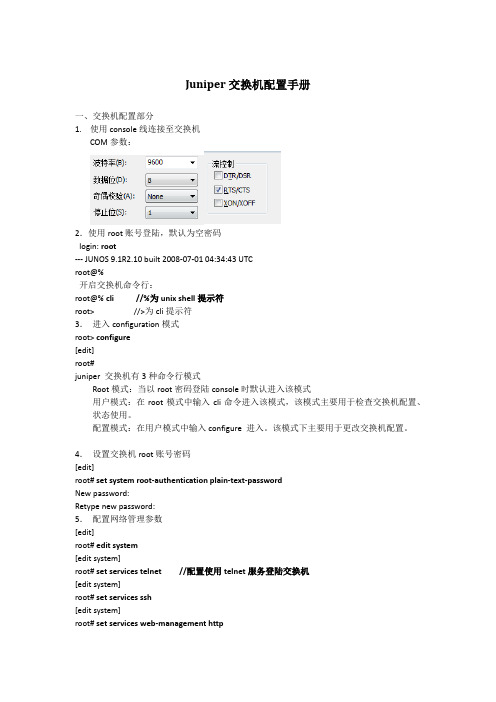
juniper交换机命令juniper 交换机配置命令整理导读:就爱阅读网友为您分享以下“juniper 交换机配置命令整理”的资讯,希望对您有所帮助,感谢您对 的支持!设置交换机名字set system host-name BaoGaoTing端口镜像set ethernet-switching-options analyzer debug input ingress interface ge-0/0/0.0set ethernet-switching-options analyzer debug input egress interface ge-0/0/0.0set ethernet-switching-options analyzer debug output interface ge-0/0/4.0Dual-partition的主要目的:解决异常断电设备无法启动的问题request system snapshot media internal slice alternate request system snapshot slice alternate //主备之间备份request system reboot slice alternate media internal // 指定从另外一个分区启动,下一次启动就会默认从上次启动的分区启动junos os,记忆功能QinQ 配置基本的set ethernet-switching-options dot1q-tunneling ether-type 0x8100 封装协议set vlans qinqvlan vlan-id 2821set vlans qinqvlan dot1q-tunnelingset interfaces ge-0/0/28 unit 0 family ethernet-switching vlan members 2821 上行端口set ethernet-switching-options dot1q-tunneling ether-type 0x8100set vlans cust1 vlan-id 100set vlans cust1 interface ge-0/0/1.0set vlans cust1 interface ge-0/0/2.0灵活的set ethernet-switching-options dot1q-tunneling ether-type 0x8100 ##set interfaces ge-0/0/27 unit 0 family ethernet-switching port-mode access ##下行端口set interfaces ge-0/0/27 unit 0 family ethernet-switching vlan members qinq ##用户Vlan为qinq 管理Vlan为Vlan600是透传上去的set interfaces ge-0/0/27 unit 0 family ethernet-switching vlan members vlan600 ** 注意点:一般情况下是不可以同时两个access的,--那样就做成trunk模式** 除非有一个vlan是dot1q-tunnel,而且需要tunnel vlan必须得有customer-vlan的,没有customer-vlan是无法提交成功的set vlans qinq vlan-id 4000 ##//灵活qinq,对于内层标签2-150的tag加上外层4000set vlans qinq interface ge-0/0/27.0set vlans qinq dot1q-tunneling customer-vlans 2-150接入交换机配置setinterfaces ge-0/1/1 unit 0 family ethernet-switching port-mode trunkset interfaces ge-0/1/1 unit 0 family ethernet-switching vlan members 2set interfaces ge-0/1/1 unit 0 family ethernet-switching native-vlan-id 600 **由于上联汇聚交换机的端口为Access口所以要透传的Vlan为native-Vlan##root用户名密码set system root-authentication encrypted-password "$1$z2Z28Ixe$AScMP7uMvMHY3fy8dgtm11" ##用户idset system login user juniper uid 2100 ##设置root用户为超级用户set system login user juniper class super-user##远程用户名和密码set system login user juniper authentication encrypted-password "$1$qUdu0s0Z$vGS88V0jrjhsPnQOTF9oy/" ##启用telnet set system services telnet connection-limit 10 set system services telnet rate-limit 10##端口模式为accesset interfaces ge-0/0/0 unit 0 family ethernet-switching port-mode access ##端口加入Vlan为600 set interfaces ge-0/0/0 unit 0 family ethernet-switching vlan members 600 ##端口为trunkset interfaces ge-0/1/0 unit 0 family ethernet-switching port-mode trunk ##允许通过Vlan为600 set interfaces ge-0/1/0 unit 0 family ethernet-switching vlan members 600 ##设置Vlan600的ip地址set interfaces vlan unit 600 family inet address 172.30.0.16/24 ##设置默认网关set routing-options static route 0.0.0.0/0 next-hop 172.30.0.1 ##开启Vlan的三层接口set vlans default l3-interface vlan.0 ##创建Vlan 名字为mgt id 为600 set vlans mgt vlan-id 600 ##开启Vlans mgt的三层接口set vlans mgt l3-interface vlan.600 ##开启Vlans mgt的三层接口set poe interface all X配置VLAN的L3接口地址set vlans name l3-interface vlan.xxset interface vlan xx unit xx family inet address x.x.x.x/24将某个交换端口添加到创建好的VLAN中set interface ge-0/0/x unit 0 family ethernet-switching port-mode access vlan members name 配置TRUNK端口set interface ge-0/0/23 unit 0 family ethernet-switching port-mode trunk native-vlan-id 1 vlan member xx预提交commit check清除LED灯报警clear alarm trafficclear alarm eventEX2200 ALARM告警灯亮红灯:show chassis alarmshow system alarmrequest system configuration rescue save/delete set chassis alarmmanagement-ethernet link-down ignore 管理口状态警告信息灯关闭set chassis alarm ethernet link-down ignore 交换机端口状态警告信息灯关闭igmp 开启set protocols igmp-snooping vlan alldeactivate protocols igmp-snooping开启生成树Set protocol stp恢复出厂设置load factory defaultDual-partition的主要目的:解决异常断电设备无法启动的问题request system snapshot media internal slice alternate //主备之间备份request system reboot slice alternate media internal // 指定从另外一个分区启动,下一次启动就会默认从上次启动的分区启动junos os,记忆功能dhcp 配置set system services dhcp pool 100.1.1.0/24 address-range low 100.1.1.10set system services dhcp pool 100.1.1.0/24 address-range high 100.1.1.200set system services dhcp pool 100.1.1.0/24 default-lease-time 7200set system services dhcp pool 100.1.1.0/24 router 100.1.1.254将端口设置为三层模式。
Juniper EX 系列以太网交换机 说明书

Juniper EX 系列以太网交换机操作手册Version 1.0Copyright © 2008 Juniper Networks, Inc.Juniper EX系列以太网交换机操作手册Juniper EX系列以太网交换机操作手册Juniper EX系列以太网交换机操作手册Juniper EX系列以太网交换机操作手册Juniper EX系列以太网交换机操作手册Juniper EX系列以太网交换机操作手册Juniper EX系列以太网交换机操作手册Juniper EX系列以太网交换机操作手册Juniper EX系列以太网交换机操作手册Juniper EX系列以太网交换机操作手册Juniper EX系列以太网交换机操作手册Juniper EX系列以太网交换机操作手册Juniper EX系列以太网交换机操作手册Juniper EX系列以太网交换机操作手册Juniper EX系列以太网交换机操作手册Juniper EX系列以太网交换机操作手册Juniper EX系列以太网交换机操作手册Juniper EX系列以太网交换机操作手册Juniper EX系列以太网交换机操作手册Juniper EX系列以太网交换机操作手册Juniper EX系列以太网交换机操作手册Juniper EX系列以太网交换机操作手册Juniper EX系列以太网交换机操作手册Juniper EX系列以太网交换机操作手册Juniper EX系列以太网交换机操作手册Juniper EX系列以太网交换机操作手册Juniper EX系列以太网交换机操作手册Juniper EX系列以太网交换机操作手册Juniper EX系列以太网交换机操作手册Juniper EX系列以太网交换机操作手册Juniper EX系列以太网交换机操作手册Juniper EX系列以太网交换机操作手册Juniper EX系列以太网交换机操作手册Juniper EX系列以太网交换机操作手册Juniper EX系列以太网交换机操作手册Juniper EX系列以太网交换机操作手册Juniper EX系列以太网交换机操作手册Juniper EX系列以太网交换机操作手册Juniper EX系列以太网交换机操作手册Juniper EX系列以太网交换机操作手册Juniper EX系列以太网交换机操作手册Juniper EX系列以太网交换机操作手册Juniper EX系列以太网交换机操作手册Juniper EX系列以太网交换机操作手册Juniper EX系列以太网交换机操作手册Juniper EX系列以太网交换机操作手册Juniper EX系列以太网交换机操作手册Juniper EX系列以太网交换机操作手册Juniper EX系列以太网交换机操作手册。
(完整版)JUNIPER_EX3200交换机配置

JUNIPER EX3200交换机配置1 Ex3200开机指导开机后:login: rootLast login: Fri Jan 17 22:21:55 on ttyd0--- JUNOS 7.2R3.3 built 2002-03-23 02:44:36 UTCTerminal type? [vt100] <enter>root@%注意使用root用户登录的情况下,输入帐号/密码以后,默认是进入shell模式的(而只有root用户帐号有这个现象),要输入cli命令进入用户模式:root@% cliroot>2 配置模式用户模式下输入configure命令进入配置模式,配置模式下可以对设备进行各种参数的配置root> configure[edit]root#2.1 设置root用户密码命令:set system root-authentication plain-text-password路由器初始化root用户是没有密码的,在第一次进行配置的时候必须要配置root密码才能commit成功。
密码采用字母+数字方式。
Example:lab@M7i_GZ# set system root-authentication plain-text-passwordNew password:Retype new password:2.2 添加系统用户命令:set system login user juniper uid 2000 <-设置用户名为juniper用户id为2000set system login user juniper class super-user <-设置juniper用户为超级用户set system login user juniper authentication plain-text-password <-设置juniper用户的密码2.3 设置主机名命令:set system host-name M7i_GZ <-设置主机名为M7i_GZ2.4 开启系统telnet服务命令:set system services telnet说明:系统默认是没有打开telnet功能的,只有打开telnet服务之后才能从网络上登陆到路由器。
如何配置交换机镜像端口

如何配置交换机镜像端口(网文精选)(2008-12-26 17:05:31)如果使用交换机做为整个公司接入互联网的网关,那么,想监控整个网络的数据,需要把交换机的某个端口设置为镜像口,让其他所有端口的数据都通过这个镜像口,达到监控的目的。
如何设置交换机的镜像端口呢?以下以现在比较通用的华为交换机为例子,具体说明交换机的镜像口设置。
华为交换机设置:1、在能连通交换机的机器上,点击开始”=》运行”,输入“ cmd”进入dos状态;2、通过TelNet 链接到交换机,(假设交换机Ip 地址:192。
168。
0。
1,可以通过Ipconfig/all 查询交换机IP 地址),那么输入命令行:Telnet 192.168.0.1输入用户名和密码。
3、再根据以下交换机型号,输入相应的命令,如下:【3026 等交换机镜像】S2008/S2016/S2026/S2403H/S3026 等交换机支持的都是基于端口的镜像,有两种方法:方法一1.配置镜像(观测)端口[SwitchA]monitor-port e0/82.配置被镜像端口[SwitchA]port mirror Ethernet 0/1 to Ethernet 0/2方法二1.可以一次性定义镜像和被镜像端口[SwitchA]port mirror Ethernet 0/1 to Ethernet 0/2 observing-port Ethernet 0/8举例:交换机2403h:>telnet 192.168.0.1>username:admin>password:admin>sys>monitor-port e0/8>port mirror Ethernet 0/1 to Ethernet 0/7则把交换机的1-7 端口数据镜像到端口8。
【8016 交换机端口镜像配置】1•假设8016交换机镜像端口为E1/0/15,被镜像端口为E1/0/0,设置端口1/0/15为端口镜像的观测端口。
Juniper 交换机配置教程
▪ Bridging is not supported on L3 sub-interfaces
for EX-series switches
Physical
Logical
L2 Trunk
L2 Trunk
ge-0/0/0.1
ge-0/0/2.1
ge-0/0/0.2
ge-0/0/2.1
3
Copyright © 2009 Juniper Networks, Inc.
default 0 1
orange 100 2
ge-0/0/0.0
blue
200 3
ge-0/0/1.0
purple
300 4
ge-0/0/2.0
7
Copyright © 2009 JuVnLipAerNNPetuwroprkles, Inc.
802.1Q TAGGED TRUNK LINKS
} } vlans {
orange { vlan-id 100;
} blue {
vlan-id 200; } }
VLAN Blue
Copyright © 2009 Juniper Networks, Inc.
INTER-VLAN ROUTING
Routed VLAN Interface (RVI)
vlan orange:
Admin state: Enabled
Tagging : 802.1Q Tag 100
Desription : None
Primary IP : None
Interfaces : 1. (Active = 1)
stp
: None
Tag
: None
JuniperEX系列交换机命令行配置手册
JuniperEX系列交换机命令行配置手册JuniperEX系列交换机命令行配置手册目录第一章交换机基础知识 (7)1.1认识J UNIPER交换机 (7)1.2J UNOS操作系统基础 (9)1.2.1 交换机配置模式 (9)1.2.2 交换机配置结构 (10)1.2.3 TAB和空格键的使用 (15)1.2.4 用户模式和配置模式show的区别 (16)1.2.5 如何将配置转换成set命令 (19)1.2.6 commit和rollback (20)1.3EX交换机命令菜单结构 (22)第二章操作指导 (35)2.1通过CONSOLE线连接交换机 (35)2.2 SYSTEM系统参数配置 (36)2.2.1设置root密码 (37)2.2.2设置主机名 (37)2.2.3设置DNS服务器 (37)2.2.4设置日期时间 (37)2.2.5设置NTP服务器 (38)2.2.6开启远程Telnet登陆服务 (38)2.2.7开启远程Ftp服务 (39)2.2.8开启远程ssh登陆 (39)2.2.9开启远程http登陆服务 (39)2.2.10添加/删除用户 (40)2.2.10.1添加用户 (40)2.2.10.2修改用户类别 (40)2.2.10.3 修改用户密码 (40)2.2.11用户权限设置 (41)2.3VLAN配置 (43)2.3.1 VLAN配置步骤 (43)2.3.2 VLAN配置规范要求 (44)2.3.3 添加VLAN (44)2.3.4 修改端口VLAN (46)2.3.5 删除VLAN (46)2.3.6 配置VLAN网关IP (47)2.4T RUNK配置 (47)2.4.1 Trunk配置步骤 (47)2.4.2如何设置Trunk (48)2.4.3允许/禁止VLAN通过Trunk (48)2.5端口配置 (48)2.5.1端口配置规范要求 (48)2.5.2修改端口速率 (49)2.5.3修改端口工作模式 (49)2.5.4修改端口为L3模式 (49)2.5.5 修改端口为L2模式 (50)2.6生成树配置 (50)2.6.1 RSTP协议概览 (50)2.6.2 MSTP协议概览 (53)2.6.3 STP配置实例(生成树) (54)2.6.4 RSTP配置实例(快速生成树) (55) 2.6.5 MSTP配置实例(多生成树协议) (61) 2.7端口捆绑 (66)2.7.1 端口捆绑步骤 (66)2.8ECMP负载均衡配置 (68)2.9路由协议配置 (70)2.9.1 静态路由配置 (70)2.9.1.1添加静态路由 (70)2.9.1.2 删除静态路由 (70)2.9.1.3调整静态路由优先值 (70)2.9.1.4设置备份静态路由 (70)2.9.1.5指定静态路由下一跳端口 (71) 2.9.2 OSPF配置 (71)2.9.2.1 OSPF配置步骤 (71)2.9.2.2 OSPF配置实例(单区域) (75) 2.9.2.3 OSPF路由过滤 (78)2.10端口镜像 (79)2.10.1 端口镜像的概述 (79)2.10.2 端口镜像的目的 (80)2.10.3 端口镜像的功能 (80)2.10.4 端口镜像工作原理 (80)2.10.5 端口输入输出流量镜像 (82) 2.10.6 带过滤条件的端口镜像 (83) 2.11端口MAC地址限制 (85)2.12端口广播风暴控制 (85)2.13VRRP虚拟路由冗余协议 (86)2.13.1 VRRP概览 (86)2.13.2 VRRP工作原理 (87)2.13.3 如何配置VRRP (88)2.14BFD配置(双向转发检测) (92) 2.14.1 BFD概览 (92)2.14.2 BFD介绍 (93)2.14.3 BFD的报文格式 (93)2.14.4检测模式 (95)2.14.5发送周期及检测时间 (96)2.14.6参数修改 (96)2.14.7会话建立 (97)2.14.8BFD的标准化 (100)2.14.9OSPF中配置BFD (100)2.14.10静态路由中配置BFD (101)2.15交换机F IREWALL限制功能 (101) 2.15.1限制IP地址 (102)2.15.2限制MAC地址 (102)2.16V IRTUAL-C HASSIS设置 (103)2.16.1VC知识 (103)2.16.2如何建立VC组 (104)2.16.3如何扩充VC组交换机 (106)2.16.4如何利用uplink链路组成VC (107) 2.16.5如何对VC组进行切换 (110)2.17SNMP配置 (110)2.17.1SNMP协议概览 (110)2.17.2SNMP基本简介 (110)2.17.3配置SNMP (111)2.18S YSLOG配置 (113)第三章交换机维护操作 (113)3.1交换机启动和关闭 (113)3.1.1 交换机重启 (113)3.1.2交换机关闭 (113)3.2配置备份和恢复 (114)3.2.1 交换机文件备份 (114)3.2.2配置文件的恢复 (116)3.3如何升级交换机OS (116)3.4如何恢复出厂设置 (117)3.5密码恢复 (117)3.6日常维护命令 (119)3.6.1查看序列号show chassis hardware (120)3.6.2查看硬件show chassis hardware (120)3.6.3查看软件版本show version (120)3.6.4查看CPU show chassis routing-engine (120)3.6.5ping命令 (120)3.6.6查看设备告警信息 show chassis alarms (120)3.6.7查看详细的硬件温度及状态信息show chassis environment (120)3.6.8查看接口VRRP状态信息show vrrp (120)第一章交换机基础知识1.1 认识Juniper交换机产品型号端口数端口类型PoE端口数最大电源容量(包括 PoE)EX 3200-24T 2410/100/1000B-T 8 190 (320) W EX 3200-24P 2410/100/1000B-T 24 190 (600) W EX 3200-48T 4810/100/1000B-T 8 190 (320) W EX 3200-48P 4810/100/1000B-T 48 190 (930) W产品型号端口数端口类型PoE端口数最大电源容量(包括 PoE)EX 4200-24T 24 10/100/1000B-T 8 190 (320) W EX 4200-24P 24 10/100/1000B-T 24 190 (600) W EX 4200-24F 24 100B-FX/1000B-X N/A 190 (190) WEX 4200-48T 48 10/100/1000B-T 8190 (320) WEX 4200-48P 48 10/100/1000B-T 48 190 (930) WEX 3200-48T前面面板EX 3200-48T 后面面板USBGbE管理口Console可插拔uplink模块LCD电源模块风扇模块RPS 连接头至少8 PoE端口EX 4200-48T 前面面板EX 4200-48T Rear ViewVCP (Virtual Chassis Port) 0 and1USB GbE管理口Console可插拔uplink模块LCD冗余可热插拔电源模块可插拔风扇模块至少8 PoE端口1.2 Junos操作系统基础Juniper交换机支持两种配置方式:采用命令行的CLI(command-line interface)配置方式,以及采用web浏览器界面JWeb配置方式。
JuniperEX交换机配置操作手册

root@router#exit
Exiting configuration mode
root@kenny> exit
Reboot the system? [y/n]y
Terminated
5.重新启动后,配置新的root密码。Juniper设备恢复正常。
3.
JUNOSCLI模式
设备启动,登录进入系统后输入cli,即可进入JUNOS CLI模式,可进行设备调试。JUNOS CLI有两种模式:用户模式和配置模式,区分方法是他们的提示符不一样:
root@host#
[edit]
root@host#commit
5.
EX路由交换机初始配置向导EZSETUP
在第一次登录系统后,直接输入ezsetup命令进入初始配置向导,在此向导中,顺序输入:
系统名称hostname
系统密码
是否启用Telnet服务
是否启用SSH服务
交换机管理模式:带外/带内
用缺省VLAN "default"管理
Starting CLI ...
root>
4.进入配置模式,删除root密码:
root>configure
Entering configuration mode
[edit]
root#delete system root-authentication
root@router#commit
commit complete
2.将Console线缆的DB9插头一头插到PC或者笔记本电脑的COM口上,另外一端插到Juniper设备的CONSOLE口上。。
3.打开计算机中的终端软件工具。例如:CRT或者Windows自带的超级终端。设置如下:
juniper交换机详细配置手册

命பைடு நூலகம்行配置指导手册
Version 1.0
目录 1 交换机基础知识 ........................................................................................................................................... 6
2 操作指导 .................................................................................................................................................... 30 2.1 通过CONSOLE线连接交换机 ............................................................................................................................... 30 2.2 SYSTEM系统参数配置 ......................................................................................................................................... 31 2.2.1 设置root密码 ............................................................................................................................................ 32 2.2.2 设置主机名 ............................................................................................................................................... 32 2.2.3 设置DNS服务器 ........................................................................................................................................ 32 2.2.4 设置日期时间 ........................................................................................................................................... 32 2.2.5 设置NTP服务器......................................................................................................................................... 33 2.2.6 开启远程Telnet登陆服务 ......................................................................................................................... 33 2.2.7 开启远程Ftp服务 ...................................................................................................................................... 33 2.2.8 开启远程ssh登陆 ...................................................................................................................................... 34 2.2.9 开启远程http登陆服务 ............................................................................................................................ 34 2.2.10 添加/删除用户........................................................................................................................................ 34 2.2.10.1 添加用户 ............................................................................................................................................................ 34 2.2.10.2 修改用户类别 .................................................................................................................................................... 35 2.2.10.3 修改用户密码 .................................................................................................................................................... 35 2.2.10.4 删除用户 ............................................................................................................................................................ 35 2.2.11 用户权限设置 ......................................................................................................................................... 35 2.3 VLAN配置 .......................................................................................................................................................... 36 2.3.1 VLAN配置步骤 .......................................................................................................................................... 37 2.3.2 VLAN配置规范要求 .................................................................................................................................. 37 2.3.3 添加VLAN .................................................................................................................................................. 37 2.3.4 修改端口VLAN .......................................................................................................................................... 39 2.3.5 删除VLAN .................................................................................................................................................. 39 2.3.6 配置VLAN网关IP ....................................................................................................................................... 40 第2页 共86页
交换机镜像配置大全涵盖22种主流交换机
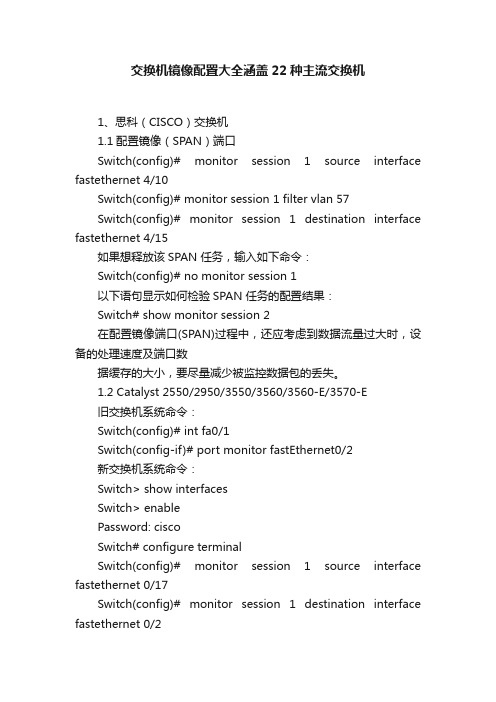
交换机镜像配置大全涵盖22种主流交换机1、思科(CISCO)交换机1.1配置镜像(SPAN)端口Switch(config)# monitor session 1 source interface fastethernet 4/10Switch(config)# monitor session 1 filter vlan 57Switch(config)# monitor session 1 destination interface fastethernet 4/15如果想释放该SPAN 任务,输入如下命令:Switch(config)# no monitor session 1以下语句显示如何检验SPAN 任务的配置结果:Switch# show monitor session 2在配置镜像端口(SPAN)过程中,还应考虑到数据流量过大时,设备的处理速度及端口数据缓存的大小,要尽量减少被监控数据包的丢失。
1.2 Catalyst 2550/2950/3550/3560/3560-E/3570-E旧交换机系统命令:Switch(config)# int fa0/1Switch(config-if)# port monitor fastEthernet0/2新交换机系统命令:Switch> show interfacesSwitch> enablePassword: ciscoSwitch# configure terminalSwitch(config)# monitor session 1 source interface fastethernet 0/17Switch(config)# monitor session 1 destination interface fastethernet 0/2Switch(config)# endSwitch# show monitor session 1 --查看镜像Switch# no monitor session 1 --清空镜像Switch# show running-config --查看运行配置Switch# copy running-config startup-config --保存到配置文件如果用display mirror 命令看到ingress:disabled,说明划分了VLAN,源数据中包含了目的端口所在的VLAN。
Juniper_EX4200_中文配置手册全集详解

EX4200/3200交换机命令配置手册目录1交换机基础知识 (6)1.1认识J UNIPER交换机 ............................................................................................................... 错误!未定义书签。
1.2J UNOS操作系统基础 (6)1.2.1 交换机配置模式 (6)1.2.2 交换机配置结构 (7)1.2.3 TAB和空格键的使用 (10)1.2.4 用户模式和配置模式show的区别 (11)1.2.5 如何将配置转换成set命令 (14)1.2.6 commit和rollback (14)1.3EX交换机命令菜单结构 (16)2操作指导 (28)2.1通过CONSOLE线连接交换机 (28)2.2 SYSTEM系统参数配置 (30)2.2.1 设置root密码 (30)2.2.2 设置主机名 (30)2.2.3 设置DNS服务器 (30)2.2.4 设置日期时间 (31)2.2.5 设置NTP服务器 (31)2.2.6 开启远程Telnet登陆服务 (31)2.2.7 开启远程Ftp服务 (31)2.2.8 开启远程ssh登陆 (32)2.2.9 开启远程http登陆服务 (32)2.2.10 添加/删除用户 (32)2.2.10.1 添加用户 (32)2.2.10.2 修改用户类别 (33)2.2.10.3 修改用户密码 (33)2.2.10.4 删除用户 (33)2.2.11 用户权限设置 (33)2.3VLAN配置 (34)2.3.1 VLAN配置步骤 (35)2.3.2 VLAN配置规范要求 (35)2.3.3 添加VLAN (35)2.3.4 修改端口VLAN (37)2.3.5 删除VLAN (37)2.3.6 配置VLAN网关IP (38)2.4.2 如何设置Trunk (38)2.4.3 允许/禁止VLAN通过Trunk (39)2.5端口配置 (39)2.5.1 端口配置规范要求 (39)2.5.2 修改端口速率 (39)2.5.3 修改端口工作模式 (39)2.5.4 修改端口为L3模式 (40)2.5.5 修改端口为L2模式 (40)2.6生成树配置 (40)2.6.1 STP配置实例 (41)2.6.2 RSTP配置实例 (42)2.6.3 MSTP配置实例 (45)2.7端口捆绑 (48)2.7.1 端口捆绑步骤 (48)2.7.2 L2端口捆绑 (49)2.7.3 L3端口捆绑 (50)2.8ECMP负载均衡配置 (50)2.9路由协议配置 (51)2.9.1 静态路由配置 (51)2.9.1.1 添加静态路由 (51)2.9.1.2 删除静态路由 (52)2.9.1.3 调整静态路由优先值 (52)2.9.1.4 设置备份静态路由 (52)2.9.1.5 指定静态路由下一跳端口 (52)2.9.2 OSPF配置 (52)2.9.2.1 OSPF配置步骤 (52)2.9.2.2 OSPF配置实例 (55)2.9.2.3 OSPF路由过滤 (57)2.10端口镜像 (58)2.10.1 端口输入输出流量镜像 (58)2.10.2 带过滤条件的端口镜像 (59)2.11端口MAC地址限制 (60)2.12端口广播风暴控制 (60)2.13VRRP配置 (60)2.13.3 如何切换VRRP (61)2.14BFD配置 (61)2.14.1 OSPF中配置BFD (62)2.14.2 静态路由中配置BFD (62)2.15交换机F IREWALL限制功能 (62)2.15.1 限制IP地 (62)2.15.2 限制MAC地址 (63)2.16V IRTUAL-C HASSIS设置 (63)2.17VC知识 (64)2.17.1 如何建立VC组 (65)2.17.2 如何扩充VC组交换机 (66)2.17.3如何利用uplink链路组成VC (67)2.17.4 如何对VC组进行切换 (69)2.18SNMP配置 (69)2.19S YSLOG配置 (70)2.20 MULTI-VRF配置 (71)2.21 MULTI-VRF OSPF配置 (72)3交换机维护操作 (72)3.1交换机启动和关闭 (73)3.1.1 重新启动 (73)3.1.2 关闭 (73)3.2配置备份和恢复 (73)3.2.1 配置备份 (73)3.2.2 配置恢复 (74)3.3如何升级交换机OS (75)3.4如何恢复出厂设置 (75)3.5密码恢复 (75)3.6日常维护命令 (77)3.6.1 查看序列号show chassis hardware (77)3.6.2 查看硬件show chassis hardware (77)3.6.3 查看软件版本show version (77)3.6.4 查看CPU show chassis routing-engine (77)3.6.5 ping命令 (77)3.6.6 查看设备告警信息show chassis alarms (77)3.6.7 查看详细的硬件温度及状态信息show chassis environment (77)3.6.8 查看接口VRRP状态信息show vrrp (77)3.6.9 收集CASE需要的信息request support information (78)4如何获取技术支持 .......................................................................................................... 错误!未定义书签。
JUNIPER EX3200交换机配置

JUNIPER EX3200交换机配置1 Ex3200开机指导开机后:login: rootLast login: Fri Jan 17 22:21:55 on ttyd0--- JUNOS 7.2R3.3 built 2002-03-23 02:44:36 UTCTerminal type? [vt100] <enter>root@%注意使用root用户登录的情况下,输入帐号/密码以后,默认是进入shell模式的(而只有root用户帐号有这个现象),要输入cli命令进入用户模式:root@% cliroot>2 配置模式用户模式下输入configure命令进入配置模式,配置模式下可以对设备进行各种参数的配置root> configure[edit]root#2.1 设置root用户密码命令:set system root-authentication plain-text-password路由器初始化root用户是没有密码的,在第一次进行配置的时候必须要配置root密码才能commit成功。
密码采用字母+数字方式。
Example:lab@M7i_GZ# set system root-authentication plain-text-passwordNew password:Retype new password:2.2 添加系统用户命令:set system login user juniper uid 2000 <-设置用户名为juniper用户id为2000set system login user juniper class super-user <-设置juniper用户为超级用户set system login user juniper authentication plain-text-password <-设置juniper用户的密码2.3 设置主机名命令:set system host-name M7i_GZ <-设置主机名为M7i_GZ2.4 开启系统telnet服务命令:set system services telnet说明:系统默认是没有打开telnet功能的,只有打开telnet服务之后才能从网络上登陆到路由器。
JUNIPER_EX3200交换机配置

JUNIPER EX3200交换机配置1 Ex3200开机指导开机后:login: rootLast login: Fri Jan 17 22:21:55 on ttyd0--- JUNOS 7.2R3.3 built 2002-03-23 02:44:36 UTCTerminal type? [vt100] <enter>root@%注意使用root用户登录的情况下,输入帐号/密码以后,默认是进入shell模式的(而只有root用户帐号有这个现象),要输入cli命令进入用户模式:root@% cliroot>2 配置模式用户模式下输入configure命令进入配置模式,配置模式下可以对设备进行各种参数的配置root> configure[edit]root#2.1 设置root用户密码命令:set system root-authentication plain-text-password路由器初始化root用户是没有密码的,在第一次进行配置的时候必须要配置root密码才能commit成功。
密码采用字母+数字方式。
Example:lab@M7i_GZ# set system root-authentication plain-text-passwordNew password:Retype new password:2.2 添加系统用户命令:set system login user juniper uid 2000 <-设置用户名为juniper用户id为2000set system login user juniper class super-user <-设置juniper用户为超级用户set system login user juniper authentication plain-text-password <-设置juniper用户的密码2.3 设置主机名命令:set system host-name M7i_GZ <-设置主机名为M7i_GZ2.4 开启系统telnet服务命令:set system services telnet说明:系统默认是没有打开telnet功能的,只有打开telnet服务之后才能从网络上登陆到路由器。
交换机端口镜像配置
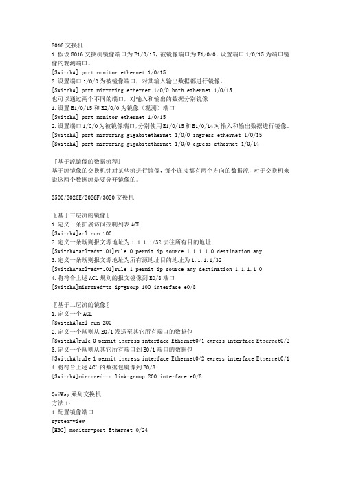
8016交换机1.假设8016交换机镜像端口为E1/0/15,被镜像端口为E1/0/0,设置端口1/0/15为端口镜像的观测端口。
[SwitchA] port monitor ethernet 1/0/152.设置端口1/0/0为被镜像端口,对其输入输出数据都进行镜像。
[SwitchA] port mirroring ethernet 1/0/0 both ethernet 1/0/15也可以通过两个不同的端口,对输入和输出的数据分别镜像1.设置E1/0/15和E2/0/0为镜像(观测)端口[SwitchA] port monitor ethernet 1/0/152.设置端口1/0/0为被镜像端口,分别使用E1/0/15和E1/0/14对输入和输出数据进行镜像。
[SwitchA] port mirroring gigabitethernet 1/0/0 ingress ethernet 1/0/15 [SwitchA] port mirroring gigabitethernet 1/0/0 egress ethernet 1/0/14『基于流镜像的数据流程』基于流镜像的交换机针对某些流进行镜像,每个连接都有两个方向的数据流,对于交换机来说这两个数据流是要分开镜像的。
3500/3026E/3026F/3050交换机〖基于三层流的镜像〗1.定义一条扩展访问控制列表ACL[SwitchA]acl num 1002.定义一条规则报文源地址为1.1.1.1/32去往所有目的地址[SwitchA-acl-adv-101]rule 0 permit ip source 1.1.1.1 0 destination any3.定义一条规则报文源地址为所有源地址目的地址为1.1.1.1/32[SwitchA-acl-adv-101]rule 1 permit ip source any destination 1.1.1.1 04.将符合上述ACL规则的报文镜像到E0/8端口[SwitchA]mirrored-to ip-group 100 interface e0/8〖基于二层流的镜像〗1.定义一个ACL[SwitchA]acl num 2002.定义一个规则从E0/1发送至其它所有端口的数据包[SwitchA]rule 0 permit ingress interface Ethernet0/1 egress interface Ethernet0/2 3.定义一个规则从其它所有端口到E0/1端口的数据包[SwitchA]rule 1 permit ingress interface Ethernet0/2 egress interface Ethernet0/1 4.将符合上述ACL的数据包镜像到E0/8[SwitchA]mirrored-to link-group 200 interface e0/8QuiWay系列交换机方法1:1.配置镜像端口system-view[H3C] monitor-port Ethernet 0/242.配置被镜像端口[H3C] port mirror Ethernet 0/1 to Ethernet 0/8方法2:[H3C] port mirror Ethernet 0/1 to Ethernet 0/8 observing-port Ethernet 0/24S3100系列交换机system-view[H3C] mirroring-group 1 local[H3C] mirroring-group 1 monitor-port Ethernet 1/0/4[H3C] mirroring-group 1 mirroring-port Ethernet 1/0/1 bothS3600系列交换机在端口视图下配置1:system-view[H3C] mirroring-group 1 local[H3C] interface gigabitEthernet 1/1/4[H3C-GigabitEthernet1/1/4] monitor-port[H3C-GigabitEthernet1/1/4] quit[H3C] interface gigabitEthernet 1/1/1[H3C-GigabitEthernet1/1/1] mirroring-port both在端口视图下配置2:system-view[H3C] mirroring-group 1 local[H3C] interface GigabitEthernet 1/1/4[H3C-GigabitEthernet1/1/4] mirroring-group 1 monitor-port[H3C-GigabitEthernet1/1/4] quit[H3C] interface GigabitEthernet 1/1/1[H3C-GigabitEthernet1/1/1] mirroring-group 1 mirroring-port both在系统视图下配置:system-view[H3C] mirroring-group 1 local[H3C] mirroring-group 1 monitor-port GigabitEthernet 1/1/4[H3C] mirroring-group 1 mirroring-port GigabitEthernet 1/1/1 bothS6500/S7500系列交换机1.以太网端口视图下配置端口镜像1) 创建端口镜像组<SWITCH> system-view[SWITCH] mirroring-group 1 local2) 进入镜像目的端口的以太网端口视图[SWITCH] interface GigabitEthernet 1/0/23) 定义当前端口为镜像目的端口[SWITCH-GigabitEthernet1/0/2] mirroring-group 1 monitor-port4) 进入镜像源端口的以太网端口视图[SWITCH] interface GigabitEthernet 1/0/15) 配置镜像源端口,同时指定被镜像报文的方向[SWITCH-GigabitEthernet1/0/1] mirroring-group 1 mirroring-port both2.系统视图下配置端口镜像1) 创建端口镜像组。
Juniper EX交换机端口镜像配置
Example: Configuring Port Mirroring for Local Monitoring of Employee Resource Use on EX Series SwitchesEX Series switches allow you to configure port mirroring to send copies of packets to either a local interface for local monitoring or to a VLAN for remote monitoring. You can use port mirroring to copy these packets:•Packets entering or exiting a port•Packets entering a VLAN on EX2200, EX3200, EX4200, or EX4500 switches•Packets exiting a VLAN on EX8200 switchesYou can analyze the mirrored traffic using a protocol analyzer application installed ona system connected to the local destination interface (or a running on a remotemonitoring station if you are sending mirrored traffic to an analyzer VLAN).This example describes how to configure an EX Series switch to mirror trafficentering interfaces connected to employee computers to an analyzer output interface on the same switch.This example describes how to configure local port mirroring:RequirementsThis example uses the following hardware and software components:•Junos OS Release 9.0 or later for EX Series switches•One EX Series switchBefore you configure port mirroring, be sure you have an understanding of portmirroring concepts.Overview and TopologyThis topic includes two related examples that describe how to mirror traffic entering ports on the switch to a destination interface on the same switch. The first example shows how to mirror all traffic entering the ports connected to employee computers.The second example shows the same scenario, but includes a filter to mirror only the employee traffic going to the Web.In this example, ge-0/0/0 and ge-0/0/1 serve as connections for employeecomputers.In this example, one interface, ge-0/0/10, is reserved for analysis of mirrored traffic. Connect a PC running a protocol analyzer application to the analyzer output interfaceto analyze the mirrored traffic.Note: Multiple ports mirrored to one interface can cause buffer overflow and dropped packets. Figure 1 shows the network topology for this example.Figure 1: Network Topology for Local Port Mirroring ExampleMirroring All Employee Traffic for Local AnalysisTo configure port mirroring for all employee traffic for local analysis, perform these tasks:CLI Quick ConfigurationTo quickly configure local port mirroring for ingress traffic to the two ports connectedto employee computers, copy the following commands and paste them into the switch terminal window:[edit]set interfaces ge-0/0/0 unit 0 family ethernet-switchingset interfaces ge-0/0/1 unit 0 family inet 192.1.1.1/24set interfaces ge-0/0/10 unit 0 family ethernet-switchingset ethernet-switching options analyzer employee–monitor input ingress interface ge-0/0/0.0set ethernet-switching options analyzer employee–monitor input ingress interface ge-0/0/1.0set ethernet-switching options analyzer employee–monitor output interface ge-0/0/10.0Step-by-Step ProcedureTo configure an analyzer called employee-monitor and specify the input (source) interfaces and the analyzer output interface:1.Configure each interface connected to employee computers as an input interface for the port-mirror analyzer thatwe are calling employee-monitor:[edit ethernet-switching-options]user@switch# set analyzer employee-monitor input ingress interface ge–0/0/0.0user@switch# set analyzer employee-monitor input ingress interface ge–0/0/1.02.Configure the output analyzer interface for the employee-monitor analyzer. This will be the destinationinterface for the mirrored packets:[edit ethernet-switching-options]user@switch# set analyzer employee-monitor output interface ge-0/0/10.0ResultsCheck the results of the configuration:[edit]user@switch# show ethernet-switching-options {analyzer employee-monitor {input {ingress {interface ge-0/0/0.0;interface ge-0/0/1.0;}}output {interface {ge-0/0/10.0;}}}}Mirroring Employee-to-Web Traffic for Local AnalysisTo configure port mirroring for employee to web traffic, perform these tasks:CLI Quick ConfigurationTo quickly configure local port mirroring of traffic from the two ports connected to employee computers, filtering so that only traffic to the external Web is mirrored, copy the following commands and paste them into the switch terminal window:[edit]set ethernet-switching-options analyzer employee–web–monitor output interface ge-0/0/10.0set firewall family ethernet-switching filter watch-employee term employee-to-corp fromdestination-address 192.0.2.16/28set firewall family ethernet-switching filter watch-employee term employee-to-corp from source-address 192.0.2.16/28set firewall family ethernet-switching filter watch-employee term employee-to-corp then acceptset firewall family ethernet-switching filter watch-employee term employee-to-web fromdestination-port 80set firewall family ethernet-switching filter watch-employee term employee-to-web then analyzer employee-web-monitorset interfaces ge-0/0/0 unit 0 family ethernet-switching filter input watch-employeeset interfaces ge-0/0/1 unit 0 family ethernet-switching filter input watch-employeeStep-by-Step ProcedureTo configure local port mirroring of employee-to-web traffic from the two portsconnected to employee computers:1.Configure the local analyzer interface:[edit interfaces]user@switch# set ge-0/0/10 unit 0 family ethernet-switching2.Configure the employee-web-monitor analyzer output (the input to the analyzer comes from the action ofthe filter):[edit ethernet-switching-options]user@switch# set analyzer employee-web-monitor output interface ge-0/0/10.03.Configure a firewall filter called watch-employee to send mirrored copies of employee requests to the Webto the employee-web-monitor analyzer. Accept all traffic to and from the corporate subnet (destination or source address of 192.0.2.16/28). Send mirrored copies of all packets destined for the Internet(destination port 80) to the employee-web-monitor analyzer.[edit firewall family ethernet-switching]user@switch# set filter watch-employee term employee-to-corp from destination-address 192.0.2.16/28user@switch# set filter watch-employee term employee-to-corp from source-address192.0.2.16/28user@switch# set filter watch-employee term employee-to-corp then acceptuser@switch# set filter watch-employee term employee-to-web from destination-port 80user@switch# set filter watch-employee term employee-to-web then analyzer employee-web-monitor4.Apply the watch-employee filter to the appropriate ports:[edit interfaces]user@switch# set ge-0/0/0 unit 0 family ethernet-switching filter input watch-employeeuser@switch# set ge-0/0/1 unit 0 family ethernet-switching filter input watch-employeeResultsCheck the results of the configuration:[edit]user@switch# show ethernet-switching-options {analyzer employee-web-monitor {output {interface ge-0/0/10.0;}}}...firewall family ethernet-switching {filter watch-employee {term employee-to-corp {from {destination-address 192.0.2.16/28;source-address192.0.2.16/28;}then accept {}term employee-to-web {from {destination-port 80;}then analyzer employee-web-monitor;}}}...interfaces {ge-0/0/0 {unit 0 {family ethernet-switching {port-mode trunk;vlan members [employee-vlan, voice-vlan];filter {input watch-employee;}}}}ge-0/0/1 {family ethernet-switching {filter {input watch-employee;}}}}VerificationTo confirm that the configuration is correct, perform these tasks:Verifying That the Analyzer Has Been Correctly CreatedPurposeVerify that the analyzer named employee-monitor or employee-web-monitor has been created on the switch with the appropriate input interfaces, and appropriate output interface.ActionYou can verify the port mirror analyzer is configured as expected using the show analyzer command.user@switch> show analyzerAnalyzer name : employee-monitorOutput interface : ge-0/0/10.0Mirror ratio : 1Loss priority : LowIngress monitored interfaces : ge-0/0/0.0Ingress monitored interfaces : ge-0/0/1.0Egress monitored interfaces : NoneMeaningThis output shows that the employee-monitor analyzer has a ratio of 1 (mirroring every packet, the default setting), a loss priority of low (set this option to high only when the analyzer output is to a VLAN), is mirroring the traffic entering the ge-0/0/0 and ge-0/0/1 interfaces, and sending the mirrored traffic to the ge-0/0/10interface.。
常见的几种交换机端口镜像配置详解(学习资料)

常见的几种交换机端口镜像配置详解端口镜像配置之DELL在交换机管理界面左边的树形菜单中,选中“Switch”(交换机)>>>“Ports”(端口)>>>“PortMirroring”(端口镜像),右边将打开“PortMirroring”(端口镜像)页面。
该页面中的参数解释如下:Add(添加):添加端口镜像操作DestinationPort(目的地端口):定义端口通信要镜像到的端口号;SourcePort(源端口):定义被镜像端口的端口号。
最多可以将8个被镜像端口镜像到一个镜像端口;Type(类型):指定要镜像的端口通信类型。
可能的字段值包括:“RX”-表示镜像进入网络的数据;“TX”-表示镜像流出网络的数据;Both()-表示镜像所有数据。
Status(状态):表示端口的状态。
可能的字段值包括:“Active”-表示端口被启用;“NotActive”-表示端口被禁用。
Remove(删除):删除端口镜像会话。
可能的字段值包括:“已选取”-删除端口镜像会话;“未选取”-保留端口镜像会话。
具体端口镜像配置:1.在PortMirroring对话框中的DestinationPort中选中目的端口(端口镜像),再单击Add按钮;2.在系统将打开“AddSourcePort”(添加源端口)页面中,定义“SourcePort”(源端口)和“Type”(类型)字段,并单击“ApplyChanges”(应用更改),使系统接收更改。
(注:如果需要从端口镜像会话删除副本端口,请打开“PortMirroring”(端口镜像)页面,选取“Remove”(删除)复选框,再单击“ApplyChanges”(应用更改)。
系统将删除端口镜像会话,并更新设备。
)以下是CLI命令实例:1.Console(config)#interfaceethernet1/e12.3.Console(config-if)#portmonitor1/e84.5.Console#showportsmonitor6.7.SourceportDestinationPortTypeStatus8.9.---------------------------------------10.11.1/e11/e8RX,TXActive下面我们来看看具体的几种类型的交换机是如何进行端口镜像配置的:Juniper交换机的端口镜像配置方法JuniperM系列和T系列交换机端口镜像配置方法usen@router#showforwarding-optionsport-mirroring{input{familyinet;rate;run-length;}outputint erface{next-hop;}no-filter-check;}}选择将抽样的流量发送到哪个目的端口user@router#showfirewallfiltermirror-samplefrom{...}then{sample;accept;}定义抽样过滤器,选择感兴趣的流量user@router#showinterfaceunit0familyinetfilter{inputmirror-sample;}选择将抽样的过滤器应用到某个端口Nortel8000交换机的端口镜像配置方法Software3.2.0.0以前的版本,支持一组端口镜像,10个source,一个destinationSoftware3.2.0.0后的版本,支持2组镜像,(说明:通常8个ethernet口为一个电路集成板,destination 不可以在同一个板子上,即1-8口上只允许有一个destination),支持25个source。
Juniper交换机配置手册
Juniper交换机配置手册一、交换机配置部分1.使用console线连接至交换机COM参数:2.使用root账号登陆,默认为空密码login: root--- JUNOS 9.1R2.10 built 2008-07-01 04:34:43 UTCroot@%开启交换机命令行:root@% cli //%为unix shell提示符root> //>为cli提示符3.进入configuration模式root> configure[edit]root#juniper 交换机有3种命令行模式Root模式:当以root密码登陆console时默认进入该模式用户模式:在root模式中输入cli命令进入该模式,该模式主要用于检查交换机配置、状态使用。
配置模式:在用户模式中输入configure 进入。
该模式下主要用于更改交换机配置。
4.设置交换机root账号密码[edit]root# set system root-authentication plain-text-passwordNew password:Retype new password:5.配置网络管理参数[edit]root# edit system[edit system]root# set services telnet //配置使用telnet服务登陆交换机[edit system]root# set services ssh[edit system]root# set services web-management http[edit system]root# commit and-quitcommit completeExiting configuration moderoot@switch>6.配置其他管理员账号密码,以添加一个admin账号为例[edit]Set system login user admin class super-user authentication plain-text-passwordNew password:Retype new password:7.提交配置文件使配置生效[edit]commit8. 配置VLAN,三层VLAN虚拟地址及VLAN接口以配置valn10 为例,下面为配置命令:[edit]set vlans vlan_10vlan-id10set vlans vlan_10 l3-interface vlan.10set interface vlan unit10family inet address192.192.0.167/24将接口划入到VLAN中set interface ge-0/0/10 unit 0 family ethernet-switching vlan members vlan_10 将接口配置成trunk 方法Set interface ge-0/0/23 unit 0 family ethernet-switching port-mode trunk vlan members all //将ge-0/0/23接口配置成为VLAN,并允许所有VLAN数据通过9. 配置链路捆绑具体命令如下:set chassis aggregated-devices ethernet device-count 5 //配置链路聚合端口数目为5个(ae0-ae4)set interface ae0 aggregated-ether-options lacp active //配置ae0接口链路聚合的模式set interface ae0 unit 0 family ethernet-switching port mode trunk vlan members all //配置ae0 为trunk并允许所有VLAN通过delete interface ge-0/0/4 //删除ge-0/0/4的默认配置delete interface ge-1/0/4set interface ge-0/0/4 ether-options 802.3ad ae0 //将ge-0/0/4接口绑定至ae0 set interface ge-1/0/4 ether-option 802.3ad ae0对端二层交换机配置使用相同方法ae接口后链路捆绑即生效10.配置路由添加一条默认路由至JUNIPER ISG1000set routing-options static route 0.0.0.0/0 next-hop 100.1.1.1;在hillstone防火墙上VPN切换时将分支点网段路由指向hillstone 5020Set routing-options static route 192.150.1.0/24 next-hop 100.1.2.1 //这条路由必须在切换VPN时添加,在切换前添加会造成VPN无法访问。
Juniper交换机(EX4200)配置指南

技术文件技术文件名称:Juniper交换机配置指南技术文件编号:版本:<V1.1>共49 页拟制戴翔审核[单击此处键入审核者]会签[单击此处键入会签者1][单击此处键入会签者2][单击此处键入会签者3][单击此处键入会签者4]标准化[单击此处键入标准化者]批准[单击此处键入批准者]修改记录目录1 引言 (5)1.1编写目的 (5)1.2内容简介 (5)1.3预期的读者和阅读建议 (5)2 术语、定义和缩略语 (5)2.1术语、定义 (5)2.2约定 (5)2.3缩略语 (6)3 认识EX4200 (7)3.1EX4200在组网中的位置 (7)3.2EX4200主要功能 (7)3.3交换机面板、指示灯 (8)3.3.1前后面板 (8)3.3.2LCD面板按键 (9)3.3.3指示灯 (10)4 认识JUNOS (12)4.1J UNOS简介 (12)4.2配置模式 (12)4.3配置结构 (13)5 开局配置指南 (14)5.1准备配置脚本 (14)5.2串口连接 (15)5.3堆叠配置 (16)5.4导入交换机脚本 (17)5.5修改基本配置 (18)5.6基本测试 (18)6 交换机配置命令 (19)6.1用户模式配置 (19)6.2系统参数配置 (20)6.2.1配置主机名 (20)6.2.2配置时区 (20)6.2.3配置root用户密码 (20)6.2.4配置用户 (21)6.2.5配置telnet/ftp/ssh服务 (21)6.2.6配置syslog (21)6.2.7配置NTP (22)6.2.8配置PoE (22)6.3端口配置 (22)6.3.1配置端口二层属性 (23)6.3.2配置端口三层属性 (23)6.3.3配置端口速率和工作模式 (23)6.4聚合组配置 (23)6.4.1配置聚合组数量 (24)6.4.2配置聚合组端口 (24)6.4.3配置聚合组属性 (24)6.4.4配置负荷分担算法 (25)6.5V LAN配置 (25)6.5.1配置Vlan端口 (25)6.5.2配置Vlan属性 (25)6.6路由配置 (25)6.6.1配置静态路由 (25)6.7安全配置 (26)6.7.1配置广播风暴选项 (26)6.7.2配置访问控制列表 (26)6.8生成树协议配置 (26)6.9其他选项配置 (26)6.9.1配置BFD (26)6.9.2配置VRRP (26)7 常用操作技巧 (27)7.1修改和删除命令 (27)7.2问号的使用 (27)7.3T AB、空格键的使用 (28)7.4S HOW命令的使用 (28)7.5管道符号的使用 (29)7.6将配置转换为SET形式 (30)7.7保存和回滚命令 (30)8 常用操作维护 (31)8.1管理口连接登陆 (31)8.2重启和关闭交换机 (32)8.3密码恢复 (33)8.4恢复出厂设置 (33)8.5配置备份 (34)8.6端口镜像 (35)9 脚本模板解析 (36)1 引言1.1 编写目的本文通过详细描述Juniper交换机(EX4200)的主要功能、操作使用和配置命令、配置规范,以及在NGHLR组网中的配置指南,指导用服现场工程实施。
最新各类交换机端口镜像配置

各类交换机端口镜像配置1、什么是端口镜像 (2)2、为什么需要端口镜像 (2)3、端口镜像的别名 (2)4、支持端口镜像的交换机 (3)5、各种交换机端口镜像配置 (3)C ISCO CATALYST交换机端口监听配置 (3)CISCO:3550IOS端口映射的举例 (3)C ATALYST 4000/5000/6000系列交换机端口监听配置(基于C AT OS) (4)3COM交换机端口监听配置 (5)DELL交换机端口监听配置 (5)N ET C ORE交换机端口监听配置 (7)I NTEL交换机端口监听配置 (7)A VAYA交换机端口监听配置 (8)港湾交换机的配置 (8)北电交换的设置 (9)华为交换机端口监听配置 (9)HP交换机端口监听配置 (10)E XTREME 交换机 (10)F OUNDRY 交换机 (12)J UNIPER 交换机 (12)1、什么是端口镜像把交换机一个或多个端口(VLAN)的数据镜像到一个或多个端口的方法。
端口镜像(Port Mirroring)可以让用户将所有的流量从一个特定的端口复制到一个镜像端口。
如果您的交换机提供端口镜像功能,则允许管理人员自行设置一个监视管理端口来监视被监视端口的数据。
监视到的数据可以通过PC上安装的网络分析软件来查看,通过对数据的分析就可以实时查看被监视端口的情况。
端口镜像选取的设备原则为网络中连接重要服务器群的交换机或路由器,或是连接到网通的出口路由器。
2、为什么需要端口镜像通常为了部署流量分析、IDS等产品需要监听网络流量,但是在目前广泛采用的交换网络中监听所有流量有相当大的困难,因此需要通过配置交换机来把一个或多个端口(VLAN)的数据转发到某一个端口来实现对网络的监听。
3、端口镜像的别名端口镜像通常有以下几种别名:●Port Mirroring通常指允许把一个端口的流量复制到另外一个端口,同时这个端口不能再传输数据。
●Monitoring Port监控端口●Spanning Port通常指允许把所有端口的流量复制到另外一个端口,同时这个端口不能再传输数据。
- 1、下载文档前请自行甄别文档内容的完整性,平台不提供额外的编辑、内容补充、找答案等附加服务。
- 2、"仅部分预览"的文档,不可在线预览部分如存在完整性等问题,可反馈申请退款(可完整预览的文档不适用该条件!)。
- 3、如文档侵犯您的权益,请联系客服反馈,我们会尽快为您处理(人工客服工作时间:9:00-18:30)。
Example: Configuring Port Mirroring for Local Monitoring of Employee Resource Use on EX Series SwitchesEX Series switches allow you to configure port mirroring to send copies of packets to either a local interface for local monitoring or to a VLAN for remote monitoring. You can use port mirroring to copy these packets:•Packets entering or exiting a port•Packets entering a VLAN on EX2200, EX3200, EX4200, or EX4500 switches•Packets exiting a VLAN on EX8200 switchesYou can analyze the mirrored traffic using a protocol analyzer application installed ona system connected to the local destination interface (or a running on a remotemonitoring station if you are sending mirrored traffic to an analyzer VLAN).This example describes how to configure an EX Series switch to mirror trafficentering interfaces connected to employee computers to an analyzer output interface on the same switch.This example describes how to configure local port mirroring:RequirementsThis example uses the following hardware and software components:•Junos OS Release 9.0 or later for EX Series switches•One EX Series switchBefore you configure port mirroring, be sure you have an understanding of portmirroring concepts.Overview and TopologyThis topic includes two related examples that describe how to mirror traffic entering ports on the switch to a destination interface on the same switch. The first example shows how to mirror all traffic entering the ports connected to employee computers.The second example shows the same scenario, but includes a filter to mirror only the employee traffic going to the Web.In this example, ge-0/0/0 and ge-0/0/1 serve as connections for employeecomputers.In this example, one interface, ge-0/0/10, is reserved for analysis of mirrored traffic. Connect a PC running a protocol analyzer application to the analyzer output interfaceto analyze the mirrored traffic.Note: Multiple ports mirrored to one interface can cause buffer overflow and dropped packets. Figure 1 shows the network topology for this example.Figure 1: Network Topology for Local Port Mirroring ExampleMirroring All Employee Traffic for Local AnalysisTo configure port mirroring for all employee traffic for local analysis, perform these tasks:CLI Quick ConfigurationTo quickly configure local port mirroring for ingress traffic to the two ports connectedto employee computers, copy the following commands and paste them into the switch terminal window:[edit]set interfaces ge-0/0/0 unit 0 family ethernet-switchingset interfaces ge-0/0/1 unit 0 family inet 192.1.1.1/24set interfaces ge-0/0/10 unit 0 family ethernet-switchingset ethernet-switching options analyzer employee–monitor input ingress interface ge-0/0/0.0set ethernet-switching options analyzer employee–monitor input ingress interface ge-0/0/1.0set ethernet-switching options analyzer employee–monitor output interface ge-0/0/10.0Step-by-Step ProcedureTo configure an analyzer called employee-monitor and specify the input (source) interfaces and the analyzer output interface:1.Configure each interface connected to employee computers as an input interface for the port-mirror analyzer thatwe are calling employee-monitor:[edit ethernet-switching-options]user@switch# set analyzer employee-monitor input ingress interface ge–0/0/0.0user@switch# set analyzer employee-monitor input ingress interface ge–0/0/1.02.Configure the output analyzer interface for the employee-monitor analyzer. This will be the destinationinterface for the mirrored packets:[edit ethernet-switching-options]user@switch# set analyzer employee-monitor output interface ge-0/0/10.0ResultsCheck the results of the configuration:[edit]user@switch# show ethernet-switching-options {analyzer employee-monitor {input {ingress {interface ge-0/0/0.0;interface ge-0/0/1.0;}}output {interface {ge-0/0/10.0;}}}}Mirroring Employee-to-Web Traffic for Local AnalysisTo configure port mirroring for employee to web traffic, perform these tasks:CLI Quick ConfigurationTo quickly configure local port mirroring of traffic from the two ports connected to employee computers, filtering so that only traffic to the external Web is mirrored, copy the following commands and paste them into the switch terminal window:[edit]set ethernet-switching-options analyzer employee–web–monitor output interface ge-0/0/10.0set firewall family ethernet-switching filter watch-employee term employee-to-corp fromdestination-address 192.0.2.16/28set firewall family ethernet-switching filter watch-employee term employee-to-corp from source-address 192.0.2.16/28set firewall family ethernet-switching filter watch-employee term employee-to-corp then acceptset firewall family ethernet-switching filter watch-employee term employee-to-web fromdestination-port 80set firewall family ethernet-switching filter watch-employee term employee-to-web then analyzer employee-web-monitorset interfaces ge-0/0/0 unit 0 family ethernet-switching filter input watch-employeeset interfaces ge-0/0/1 unit 0 family ethernet-switching filter input watch-employeeStep-by-Step ProcedureTo configure local port mirroring of employee-to-web traffic from the two portsconnected to employee computers:1.Configure the local analyzer interface:[edit interfaces]user@switch# set ge-0/0/10 unit 0 family ethernet-switching2.Configure the employee-web-monitor analyzer output (the input to the analyzer comes from the action ofthe filter):[edit ethernet-switching-options]user@switch# set analyzer employee-web-monitor output interface ge-0/0/10.03.Configure a firewall filter called watch-employee to send mirrored copies of employee requests to the Webto the employee-web-monitor analyzer. Accept all traffic to and from the corporate subnet (destination or source address of 192.0.2.16/28). Send mirrored copies of all packets destined for the Internet(destination port 80) to the employee-web-monitor analyzer.[edit firewall family ethernet-switching]user@switch# set filter watch-employee term employee-to-corp from destination-address 192.0.2.16/28user@switch# set filter watch-employee term employee-to-corp from source-address192.0.2.16/28user@switch# set filter watch-employee term employee-to-corp then acceptuser@switch# set filter watch-employee term employee-to-web from destination-port 80user@switch# set filter watch-employee term employee-to-web then analyzer employee-web-monitor4.Apply the watch-employee filter to the appropriate ports:[edit interfaces]user@switch# set ge-0/0/0 unit 0 family ethernet-switching filter input watch-employeeuser@switch# set ge-0/0/1 unit 0 family ethernet-switching filter input watch-employeeResultsCheck the results of the configuration:[edit]user@switch# show ethernet-switching-options {analyzer employee-web-monitor {output {interface ge-0/0/10.0;}}}...firewall family ethernet-switching {filter watch-employee {term employee-to-corp {from {destination-address 192.0.2.16/28;source-address192.0.2.16/28;}then accept {}term employee-to-web {from {destination-port 80;}then analyzer employee-web-monitor;}}}...interfaces {ge-0/0/0 {unit 0 {family ethernet-switching {port-mode trunk;vlan members [employee-vlan, voice-vlan];filter {input watch-employee;}}}}ge-0/0/1 {family ethernet-switching {filter {input watch-employee;}}}}VerificationTo confirm that the configuration is correct, perform these tasks:Verifying That the Analyzer Has Been Correctly CreatedPurposeVerify that the analyzer named employee-monitor or employee-web-monitor has been created on the switch with the appropriate input interfaces, and appropriate output interface.ActionYou can verify the port mirror analyzer is configured as expected using the show analyzer command.user@switch> show analyzerAnalyzer name : employee-monitorOutput interface : ge-0/0/10.0Mirror ratio : 1Loss priority : LowIngress monitored interfaces : ge-0/0/0.0Ingress monitored interfaces : ge-0/0/1.0Egress monitored interfaces : NoneMeaningThis output shows that the employee-monitor analyzer has a ratio of 1 (mirroring every packet, the default setting), a loss priority of low (set this option to high only when the analyzer output is to a VLAN), is mirroring the traffic entering the ge-0/0/0 and ge-0/0/1 interfaces, and sending the mirrored traffic to the ge-0/0/10interface.。