0.9V超低功耗MCU选型指南
ST STM32L072xx超低功耗MCU开发方案B-L072Z-LRWAN1(英文)
ST STM32L072xx超低功耗MCU开发方案B-L072Z-
LRWAN1(英文)
佚名
【期刊名称】《世界电子元器件》
【年(卷),期】2017(000)004
【摘要】ST公司的STM32L072xx系列是超低功耗MCU,具有USB2.0连接功能和高性能ARM CortexM0+32位RISC核,工作频率32MHz,存储器保护单元(MPU),高速嵌入存储器(高达192KB闪存可编存储器,6KB数据EEPROM和20KB RAM)以及增强的I/O和外设。
工作电压1.8V~3.6V,工作温度-40℃~+125℃,主要用在气/水表和工业传感器,健康和健身设备,遥控和用户接口,PC外设,游戏和GPS设备以及告警系统,有线和无线传感器与视频连接.本文介绍了STM32L072xx 系列主要特性,框图,以及评估板B-L072Z-LRWAN1 Lo Ra Discovery主要特性,框图,电路图,材料清单和PCB设计图.
【总页数】5页(P32-36)
【正文语种】中文
【中图分类】TN409
【相关文献】
1.ST STM32L496xx系列超低功耗32位ARM MCU开发方案 [J],
2.ST STM32L072xx超低功耗32位ARM MCU开发方案 [J],
3.ST STM32L476VGT6超低功耗ARM MCU开发方案 [J],
4.ST STM32L562QE超低功耗32位ARM MCU开发方案 [J],
5.ST STM32L072CZ超低功耗32位ARM MCU开发方案 [J],
因版权原因,仅展示原文概要,查看原文内容请购买。
超低功耗mcu的选型技巧与设计思路

超低功耗mcu的选型技巧与设计思路循序渐进式的功耗优化已经不再是超低功耗mcu的游戏规则,而是突飞猛进模式,与功耗相关的很多指标都不断刷新记录。
我们在选择合适的超低功耗mcu时要掌握必要的技巧,在应用时还需要一些设计方向与思路才能够更好的应用。
一:超低功耗mcu-低功耗mcu的选择方法嵌入式微控制器(mcu)的功耗在当今电池供电应用中正变得越来越举足轻重。
大多mcu 芯片厂商都提供低功耗低功耗产品,但是选择一款最适合您自己应用的产品并非易事,并不像对比数据表前面的数据那么简单。
我们必须详细对比mcu 功能,以便找到功耗最低的产品,这些功能包括:断电模式定时系统事件驱动功能片上外设掉电检测与保护漏电流处理效率。
----在低功耗设计中,平均电流消耗往往决定电池寿命。
例如,如果某个应用采用额定电流为400mAh 的Eveready 高电量9V 1222 型电池的话,要提供一年的电池寿命其平均电流消耗必须低于400mAh/8760h,即45.7uA。
----在使mcu 能够达到电流预算的所有功能中,断电模式最重要。
低功耗mcu 具有可提供不同级别功能的断电模式。
例如,TI 超低功耗mcu MSP430 系列产品可以提供5 种断电模式。
低功耗模式0 (LPM0)会关闭CPU,但是保持其他功能正常运转。
LPM1 与LPM2 模式在禁用功能列表中增加了各种时钟功能。
LPM3 是最常用的低功耗模式,只保持低频率时钟振荡器以及采用该时钟的外设运行。
LPM3 通常称为实时时钟模式,因为它允许定时器采用低功耗32768Hz 时钟源运行,电流消耗低于1uA,同时还可定期激活系统。
最后,LPM4 完全关闭器件上的包括RAM 存储在内的所有功能,电流消耗仅100 毫微安。
----时钟系统是mcu功耗的关键。
应用可以每秒多次或几百次进入与退出各种低功耗模式。
进入或退出低功耗模式以及快速处理数据的功能极为重要,因为CPU会在等待时钟稳定下来期间浪费电流。
STMCU低功耗产品系列详解

Clock Controller
Debug ModuleSWIM
Up to 41 I/Os
PVD
Xtal 32,768 KHz
DMA
12 bit DAC
2xComparators
Boot ROM
LCD driverUp to 4 x 28
1x16 bit TimerAdv Control3 Channels
超低功耗微控制器平台的关键词
低功耗的承诺从STM8L到STM32L完整的低功耗微控制器平台采用最新、超低漏电流的工艺极大的改善包括动态和静态的功耗高效率的承诺由于采用最新的架构,性能/功耗比达到新高运行模式功耗低至:150 µA/MHz在低功耗模式下,仅需 350nA,SRAM和寄存器数据还可以保留优化的产品分布采用通用单片机从8位到32位全覆盖的策略针对特殊的应用,提供片上集成的安全特性最佳的性价比
64 pins LQFP(10x10)
STM8L152M84 KB RAM
STM8L151M84 KB RAM
80 pins LQFP(14x14)
STM8L101 8K 结构框图
SPI
USART
I²C
2x16 bit Timer2 Channels
1x8-bit Timer
Ind. Wd with 38KHz int.
所有都包含:
USART, SPI, I2C
看门狗(STM8L15x 具有双看门狗)
多通道16-bit 定时器
内置 16 MHz 和 38 kHz RC 振荡器
复位电路(上电复位,掉电复位)
Up to 8 KB Flash
STM8L101
Up to 1.5 KB SRAM
MCU选型指南
A change bar appears in the left margin to mark the location of new or revised information.
SG1006–2 SG1006Q12008
Because of an order from the United States International Trade Commission, BGA-packaged product lines and part numbers indicated here currently are not available from Freescale for import or sale in the United States prior to September 2010: DSP56852VFE, DSP56F807VF80, DSP56F807VF80E, MC56F8357VVFE, MC56F8367VVFE
FREESCALE’S 8-BIT PRODUCTS SUMMARY
For complete part number information and temperature definitions, refer to Product Numbering System on page SG1006-9.
FREESCALE’S 8-BIT PRODUCTS SUMMARY (continued)
For complete part number information and temperature definitions, refer to Product Numbering System on page SG1006-9.
General Purpose Products (continued)
Silicon Laboratories 微控制器低功耗选择指南说明书

How to Pick the Right Microcontroller Based on Low-PowerSpecificationsIntroductionChoosing the right ultra-low-power microcontroller (MCU) for your next embedded design can be a confusing task when you compare claimed current consumption specifications in a myriad of data sheets provided by MCU vendors. In many cases, developers initially scan the first page of a data sheet as a reference point to gain basic information about an MCU, including peripherals, operating speed, package information, number of GPIOs and power characteristics. This approach works well to assess an MCU’s overall functionality, but it is not particularly useful when trying to gauge low-power characteristics.To get a broader view of an M CU’s true low-power operation, developers must take into consideration current consumption, state retention, wake-up time, wake-up sources and peripherals that are capable of operating while in low-power mode. Developers must compare a common operating mode to gain a balanced, apples-to-apples comparison among competing low-power MCUs. It is also important to take into consideration any additional functionality or peripherals that can reduce total system power and available evaluation tools that can make an engineer’s job easier.Microcontroller vendors will usually list the lowest power achievable on the first page of the data sheet. Although the device may be capable of achieving the specification in the data sheet, the actual operating mode may not be practical and useful in a real-world application. Some of the non-advertised features of the lowest power mode may include a very slow wake time, no state or RAM retention, or a reduced operating voltage range.To get around the variety of low-power specifications, developers must identify a common operating mode consisting of two sections: electrical specifications and low-power functionality.Comparing Electrical Specifications of MicrocontrollersThe electrical specifications are available in the data sheet, but determining which specifications are relevant may require some digging. Usually the electrical specifications are organized by vendor-specific power mode. This makes assessment slightly more difficult, as it requires knowledge and familiarity with the functionality of each power mode.In general, it is beneficial to define a set of operating conditions and then map them to a power mode. For example, the developer might define the following set of operating conditions:∙Sleep mode current consumption with state and RAM retentiono All other peripherals disabled∙Sleep mode current consumption with RTC running with state and RAM retentiono RTC enabled and running all other peripherals disabled.∙Wake time∙Supply voltage rangeOnce the operating conditions are clearly defined, it should be easy to determine the applicable vendor-specific power mode.Additional Low-Power FunctionalityThe second section, low-power functionality, is not as easy to locate in the vendor’s documentation and may be spread across the data sheet and reference manual. Examples of low-power functionality include: ∙Available wake sources∙How code resumes execution∙Peripherals capable of operating in sleep mode.Once the common operating mode has been clearly defined, developers can begin to examine the documentation in more detail.While going through this exercise of compiling data, keep in mind that there may be some MCU-specific features that can further optimize an application for ultra-low power. Optimizations may reduce bill of material (BOM) costs, provide longer product life or provide greater design flexibility. For example, an on-chip dc-dc converter can efficiently provide power to the system and decrease power consumption. This can enable the use of smaller batteries, which will decrease the overall BOM costs, or provide power budget flexibility. A variety of wake sources can provide design flexibility and allow the microcontroller to stay in the lowest power mode as long as possible, further reducing the average current consumption of the application.Allowing firmware to scale the internal supply voltage is another optimization knob available to the developer. If an MCU is operating at a slow frequency, it may be possible to decrease the supply voltage and save power. Selective clock gating allows hardware blocks to be disconnected from the active circuits, preventing inactive peripherals from consuming power. These types of features are not comprehended by supply current specifications that are commonly used to rank low-power MCUs, but are critical to achieving the lowest overall system power consumption.Reducing Complexity Using ToolsAs MCUs become more and more configurable to achieve the lowest power consumption, they also can become more complex. To cope with this increased complexity, developers should take a close look at the evaluation platforms available for an MCU and the overall ease of implementing a solution. For example, the development board and software tools used to program the MCU should be intuitive and easy-to-use. Hardware that is difficult to understand or use is not likely to lead to an easy firmware development process. From a firmware perspective, MCU vendors should supply firmware examples that can recreate specifications from the data sheet. If advertised current consumption specifications cannot be recreated on an evaluation platform, it is likely that it will be just as difficult (if not impossible) to configure the MCU to achieve these numbers on custom hardware. Giving customers a variety of code examples that can be used as a starting point for their code development can reduce time-to-market and help engineers learn to use a device.Graphical configuration tools can aid in development and help the developer gain a deeper understanding of an MCU. When developing low-power applications, it is helpful to know where the total consumed power is going. This information is useful because it highlights what aspect of a design needs to be further optimized and can also help the developer understand the overall architecture of the device. Ideally, low-power configuration tools could give tips on further reducing power as well as highlight any configuration errors that were detected throughout the configuration process. For example, the Power Estimator utility within Silicon Labs’ AppBuilder graphical configuration tool provides Power Tips that give configuration guidance and a power-budget pie chart showing how much power is consumed and which peripherals are consuming the power. As configuration changes are made, the pie chart automatically updates.Figure 1. Power Estimator Enables Developers to Optimize for Lowest Current Consumption To facilitate the microcontroller comparison process, the following table provides a list of common operating modes, as well as system-level optimizations and development tools available for Silicon Labs’32-bit SiM3L1xx MCUs based on the ARM® Cortex™-M3 core.SummaryEvaluating and selecting a microcontroller for a low-power application requires more than a quick scan of the first page of the data sheet. Determining which MCU provides the lowest overall system power requires developers to know the device’s supply current specifications, as well as any system-level optimizations that can reduce the overall supply current.Unfortunately, each MCU vendor specifies operating conditions differently and in some cases advertises a low-power number that is available in an unusable mode. Using a common operating mode to compare MCUs will prevent developers from being misled by vendor claims of ultra-low-power operation.Once the electrical characteristics of a device are understood and quantified, developers should take a look at the evaluation platform and software tools available. These considerations are crucial in getting an engineering team up and running quickly and should be included in the final microcontroller selection process. Find out more about Silicon Labs’ microcontrollers, including 8-bit and 32-bit MCUs at/mcu.# # #Silicon Labs invests in research and development to help our customers differentiate in the market with innovative low-power, small size, analog intensive, mixed-signal solutions. Silicon Labs' extensive patent portfolio is a testament to our unique approach and world-class engineering team. Patent: /patent-notice© 2013, Silicon Laboratories Inc. ClockBuilder, DSPLL, Ember, EZMac, EZRadio, EZRadioPRO, EZLink, ISOmodem, Precision32, ProSLIC, QuickSense, Silicon Laboratories and the Silicon Labs logo are trademarks or registered trademarks of Silicon Laboratories Inc. ARM and Cortex-M3 are trademarks or registered trademarks of ARM Holdings. ZigBee is a registered trademark of ZigBee Alliance, Inc. All other product or service names are the property of their respective owners.。
华大低功耗 mcu选型手册

华大低功耗 mcu选型手册
华大低功耗MCU选型手册是针对用户对低功耗、高效率的MCU的需求而编写的,为用户提供了多种型号的MCU选择。
在选择MCU时,需要考虑以下几个关键因素:
1. 功耗:低功耗MCU在电池供电的应用中尤为重要,可以延长电池寿命。
2. 性能:MCU的性能应满足应用需求,包括运算速度、内存大小等。
3. 外设接口:根据具体应用,可能需要不同的外设接口,如UART、SPI、I2C等。
4. 开发工具:应选择与MCU配套的开发工具,以便于开发调试。
基于以上考虑因素,华大低功耗MCU选型手册提供了多种型号的MCU供用户选择,包括HC32F003系列、HC32F4A0系列等。
这些MCU具有低功耗、高性能、丰富的外设接口等特点,适用于各种应用场景。
此外,华大还提供了完善的开发工具,如Keil、IAR等,以帮助用户快速开发MCU应用程序。
总之,华大低功耗MCU选型手册为用户提供了多种选择,用户可以根据实际需求选择最适合的MCU型号。
同时,华大还提供了完善的开发工具和服务,帮助用户快速开发出高效、可靠的MCU应用程序。
MCU选择和应用技巧

MCU选择和应⽤技巧MCU选择和应⽤技巧本刊编辑∶Robin Zhang在现代嵌⼊式开发领域,通过了解客户需求和电⼦产品趋势,搜集市⾯上⼤量的不同型号的MCU资料,结合市场上刚出现的低成本⾼性能MCU新产品,是成功进⾏MCU选型的基础。
⼀般来说,嵌⼊式系统开发⼈员在选择MCU 时,通常遵循四项主要标准∶功能、可⽤性、成本和熟悉程度。
本⽂通过资料汇编,介绍⼀些常⽤的MCU选择和应⽤技巧。
微控制器(Microcontroller;MCU)是⼀种⽆所不在的嵌⼊式控制晶⽚,玩具、家电、医疗、汽车等领域都有其存在,负责各种感测、监控⼯作,例如我们常见的电饭煲、电磁炉、咖啡壶等内部均由MCU负责感测⽔温,并接受使⽤者的指⽰是否该加温、沸腾,同样的冷⽓机的温控也是⽤MCU来实现。
此外,如桌上电脑所⽤的键盘、滑⿏等也各有⼀颗MCU,负责将敲打的键码、指标的X/Y 轴位移偏量等资讯回传给电脑CPU。
对於选择MCU进⾏设计的系统设计师来说,可获得的⼤量的不同型号MCU会让选型⼯作变得复杂,如SiliconLabs⼯作电压低⾄0.9V的8位元MCU,德州仪器针对低功耗应⽤的多款16位元MSP430,飞思卡尔和英飞针对汽车应⽤的MCU⽅案,Atmel的AVR系列和Mi cro chip的PIC系列⼀直在推陈出新……虽然新的32位ARM核Cor tex-m3处理器已经发布许久,古⽼的8位8051核还是在不同MCU中占领主流地位……⾯对缤纷多彩的MCU世界,正确把握MCU发展趋势,熟悉MCU架构,甚⾄於借助选择⼯具进⾏分析⽐较就显得极其必要。
MCU市场的价值⼀、分析趋势正是由於应⽤⼴泛,MCU市场才没有像其他处理晶⽚(如CPU、GPU)那样形成垄断,MCU晶⽚业者只要能贴近某⼀产业或深耕某⼀应⽤的控制需求,就能在市场上争得⼀席之地。
就应⽤趋势看,MCU市场⽬前可以说是百花齐放,处处呈现春⾊和希望。
1、32位MCU正在成为主⼒据国际半导体贸易统计显⽰,8/16位元晶⽚仍然占据著MCU市场56%的销量和40%的销售额,最流⾏的8位Intel架构的8051晶⽚平均每年销售33亿⽚,⼤约是32位PC CPU销量的30倍,甚⾄最早於1971年⾯世的低端4位元晶⽚的销量也只⽐它们的最⾼销量低15%,嵌⼊式系统开发者仍然在使⽤这些晶⽚,因为它们具有极低的价格、微功耗,以及⼩的体积,可以为⼏乎任何应⽤增加智慧功能。
单片机选型有诀窍:根据数值选择低功耗MCU
单片机选型有诀窍:根据数值选择低功耗MCU
根据数据手册列出的电流消耗规格来比较和选择低功耗单片机(MCU)是一项比较困难的任务。
在大多数情况下,选择MCU 的开发人员会先初步看看数
据手册第一页,作为快速获得器件信息的参考点,其中包括外设、运行速度、封装信息、GPIO 引脚数量和供电特性等。
这种方法对于获得器件的整体性能
很有效,但是在评估低功耗特性时却不实用。
为了对低功耗操作有全面了解,开发人员还要考虑电流消耗、状态保持、唤醒时间、唤醒源,以及低功耗模式下可运行的外设等。
开发人员在相同操作模式下对比同类低功耗MCU,以获得客观的逐项比较结果。
另外,易用的评估
工具也非常重要,因为能评估整体系统功耗的额外功能和外设,使工程师的工作更加容易。
MCU 供应商通常会在数据手册第一页列出最低功耗值。
虽然器件可能实现
数据手册中提到的规格,但是实际的操作模式可能在应用中不一致。
某些不利的低功耗特性并未列出,包括极慢的唤醒时间、无状态保持或RAM 保持功能,或者操作电压范围缩小。
为了深入了解各种低功耗特性,开发人员需定义相同的操作模式,其中包括两部分:电气规格和低功耗功能。
电气规格比较
电气性能规格罗列在数据手册中,通过仔细研究才能判断哪种规格更加重要。
通常电气规范依据供应商定义的电源模式组织分类,这将使评估更加困难,因为需要熟悉每种电源模式的功能。
一般情况下,定义一系列操作条件并对应到一种电源模式更有意义。
例如,开发人员可能会定义下面一组操作条件:
- 状态保持和RAM 保持条件下的休眠模式电流消耗
o 所有其他外设禁用。
超低功耗微控制单元
超低功耗微控制单元(MCU)是一种专注于控制功能的芯片,内部集成了具有高性能的处理能力和存储能力的CPU,同时具有极低的功耗,是专为需求较低的应用场景,如物联网(IoT)设备、传感器节点、可穿戴设备等设计的。
超低功耗MCU非常注重功耗的降低,以延长电池寿命和提高能效。
它们通常能够在极低功耗下运行,只需要几微安的电流,从而实现更长的电池寿命。
此外,超低功耗MCU通常采用先
进的制造工艺和优化的电路设计,以实现更高的能效和更长的电池寿命。
同时,它们也支持多种低功耗模式,可以根据应用需求进行选择。
总的来说,超低功耗MCU是现代电子
产品设计中不可或缺的一部分,特别是在电池供电的设备中,如智能手表、健康追踪器等。
通过使用超低功耗MCU,这些设备能够在保证性能的同时,实现更长的电池寿命和更高的能效。
MSP430x09x 系列 MCU 在电动剃须刀中的应用
MSP430x09x 系列MCU 在电动剃须刀中的应用【电源网】MSP430x09x 是TI 推出的业界首款名符其实的0.9V 微控制器(MCU),它的出现让便携式设备中真正使用单电池供电成为可能,将推动单节电池供电的、更小巧、更低成本的便携式产品的发展。
与现有号称0.9V技术的MCU 不同,MSP430x09x 能够以0.9V 的低电压运行所有模拟和数字逻辑,因此该系列MCU 无需板载升压转换器,从而可为整体系统降低功耗,减少了对外部电路的需求。
同时,在降低工作电压的情况下,仍继承了MSP430 系列单片机原有的优秀特性和丰富外设,并开创性的设计了功能丰富的模拟功能模块—模拟功能池(A-Pool)。
本文将介绍MSP430x09x 系列MCU 在电动剃须刀系统中的应用,并着重阐述该系统的软硬件设计。
1 MSP430x09x 简介MSP430x09x 是MSP430 系列单片机中首款0.9V 工作电压的MCU。
这一系列功能强大,能够方便的应用于微型电机控制,红外传输以及电源检测等场合中,另外,其0.9V 工作特性可以在单电池供电的消费类电子中得到广泛应用。
MSP430x09x 包含丰富的功能模块(见图1)。
该系列解决方案不仅高度整合了16 位定时器、看门狗定时器、11 个带中断功能的I/O 以及零功耗低压复位功能(BOR),此外还集成了可配置为ADC、DAC、比较器、系统电压监控器(SVS)以及温度传感器的全新模拟功能池外设,全部工作电压仅为0.9V。
16 位的RISC 架构CPU 及其指令集可与现有MSP430 MCU 器件相兼容,工作频率高达4MHz,而且工作模式下耗电量仅为45μA/MHz。
MSP430x09x 系列支持高达2kB RAM 与2kB ROM 的3 种0.9V MCU 版本— MSP430L092 (RAM)、MSP430C091(ROM) 与MSP430C092 (ROM),可根据需要提供多种选择。
低功耗MCU的选择
电流 川 ‘ 以低到 0 . 1 I J A 随荇产品性能的 r I 要求 , 3 2他 M( X1 叶 『 I
脱 计进 入低 功 耗 领域 .… _ r A R M 构的 C o d e x — M O的 低功 牦 内恢 l 是 M S P 3 { } ( ; 2 5 5 3卞 ¨ S q 、 M3 2 1 " 、 ( ) I I 的 部分 时钟 树 (  ̄ 9 x  ̄ I - L
鄙 ~ 娜
条 主要 的产 『 线 ,
遴
辫
H S E O 8 CI M t 4 z
_
核的 M ( : 【 j 最 为 合适 这 样 的 流 芯 片 r 公- 的 l 』 ) 系列. 、 X t
公i d 的l P C 8 0 0系列 , A t n l e l 公・ 可 的S A MI 2系列 其
I 河j 匕 l
EBEI NO NGJ
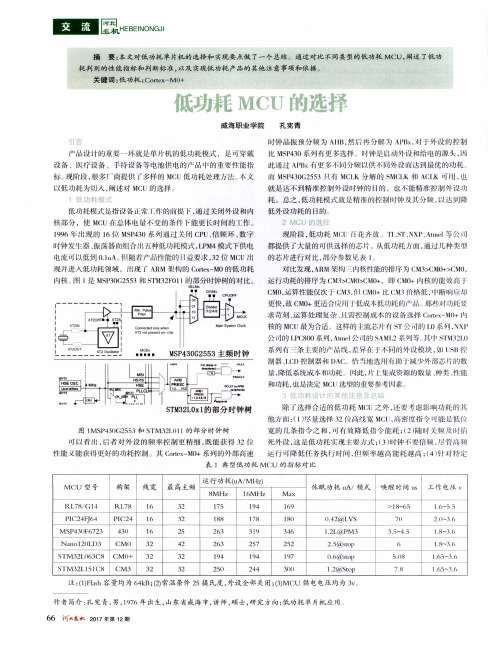
摘
要: 本 文对 低 功 耗 单 片机 的 选 择 和 实现 要 点做 了一 个 总结 。通 过 对 比 不 同类 型 的低 功 耗 MCU, 阐述 了低 功
耗判别的性能指标和判断标 准 , 以及 实现低功耗 产品的其他 注意事项和依据。
关键词 : 低功耗 ; C o r t e x — M【 】 +
议 、 疗 没 备 、 r特 设 箭 等 电池 供 l 乜的 产 品 中 的 五 嘤 能 指 柄i 阶段 , 很多厂f f { f 提供 _ r多样 的 M ( L 低 功 耗 处理 ‘ 法 、 小 义 以低 功 耗 为切 人 , 削述埘 M C [ J 的选 择 低功 托模 式 是 指 没 l j 常 T 作 的 捉 下 , 通 过 火 闭 外 没 和 内 卡 戈 部 分 ,使 M( : 【 j 总 体 电 艟 变 的 条什 i " t i E - 更 长H ; J f , J 的 r 作。 1 9 9 6 …脱 的 1 6他 M S P 4 3 0系 列迎 过 火 闭 C P [ J 、 倍频环 、 数 字
MCU芯片选型文档
汽车级产品;因此需选用汽车级MCU。
4.2 实用性 要从MCU的供货渠道、货源充足程度及供应商信誉等角度对MCU进行选型,确保所选择的型号能满足后
续的产品批量生产的需求。
4.3 可开发性 选用的MCU芯片要有可靠的开发手段,如程序开发工具、仿真调扩展性,在设计阶段采取冗余设计。如当2路CAN通信可恰好满足系统需求时,可选择
4 MCU选型原则 芯片的选型工作是一件重要而费心的事情,如果选型得当,则设计出的产品就会性价比较高且工作稳
定;反之则可能造成产品成本过高或影响产品正常运行,甚至达不到预期的设计效果。MCU的选型工作需从 以下几个方面进行:
4.1 技术性 从MCU的技术指标角度,对MCU进行选型,确保所选择的MCU能在一定技术条件下能可靠运行。BMS属于
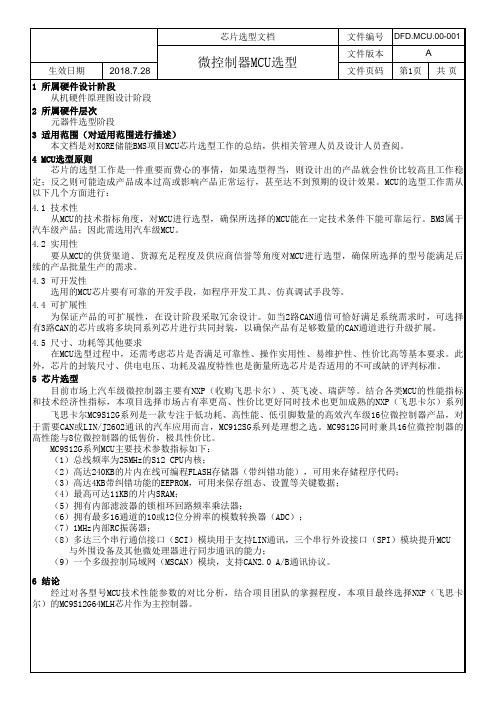
芯片选型文档
文件编号 DFD.MCU.00-001
生效日期
2018.7.28
微控制器MCU选型
文件版本 文件页码
A 第1页 共 页
1 所属硬件设计阶段 从机硬件原理图设计阶段
2 所属硬件层次 元器件选型阶段
3 适用范围(对适用范围进行描述) 本文档是对KORE储能BMS项目MCU芯片选型工作的总结,供相关管理人员及设计人员查阅。
如何正确选择低功耗MCU
如何正确选择低功耗MCU
嵌入式微控制器(MCU)的功耗在当今电池供电应用中正变得越来越举足轻重。
大多MCU 芯片厂商都提供低功耗产品,但是选择一款最适合您自己应用的产品并非易事,并不像对比数据表前面的数据那么简单。
我们必须详细对
比MCU 功能,以便找到功耗最低的产品,这些功能包括:
断电模式
定时系统
事件驱动功能
片上外设
掉电检测与保护
漏电流
处理效率
在低功耗设计中,平均电流消耗往往决定电池寿命。
例如,如果某个应
用采用额定电流为400mAh 的Eveready 高电量9V 1222 型电池的话,要提供一年的电池寿命其平均电流消耗必须低于400mAh/8760h,即45.7uA。
图 1 说明:应用消耗的电流越大,所提供的寿命越短,同时仍然保持较低的平均电
流消耗。
图1
在使MCU 能够达到电流预算的所有功能中,断电模式最重要。
低功耗MCU 具有可提供不同级别功能的断电模式。
例如,TI 超低功耗MCU MSP430 系列产品可以提供 5 种断电模式。
低功耗模式0 (LPM0) 会关闭CPU,但是保持其他功能正常运转。
LPM1 与LPM2 模式在禁用功能列表中。
恩智浦 ARM926EJ-S处理器 说明书

上,还有一个灵活的LCD控制器,它支持STN和TFT面板,并提供一 个专用DMA控制器和高达1024 x 768 的可编程显示分辨率及16M 色。 多个串行通信接口提高了设计灵活性,提供了较大的 缓冲区容 量,并可提供较高的处理能力。LPC3240和LPC3250 一个带DMA控制器的10/100 Ethernet MAC接口。 此外每个LPC32x0微控制器还有一个USB接口,支持DEVICE,HOST和 On-The-Go (OTG)工作、4个标准16C550 UART (一个支持IrDA)、3 个高速(高达921,600 bps)UART、2个快速I C总线(400 Kbps)接口 (支持从站、单主机和多主机)、2个SPI/SSP端口和自动键盘扫 描功能 (支持8x8键) 。 此外每个LPC32x0微控制器还有2个I S接口, 每个接口均有独立的输入通道和输出通道。每个通道均可独立运 行于3个管脚;而只需四个管脚,就可构成一个I S接口的输入和输 出。 每个LPC32x0微控制器都有一个带3个通道和一个触摸屏接口的 10-位、 400-kHz A/D转换器、 5个带捕获/比较通道的32-位定时器、 一个由实时时钟驱动的32-位定时器、11个PWM通道和一个看门狗 定时器。此外每个LPC32x0微控制器还有一个具有独立时钟和功率 耗域的实时时钟、一个专用32-kHz振荡器、一个安全数字(SD)接 口和一个能支持多达73个中断源的集成中断控制器。 数据传送是由一个8路通用DMA控制器进行管理的,该控制器可用 于SD端口、UART、I S端口、SPI接口或者存储器间的传送。 7层、32位104-MHz AHB矩阵为7个AHB主设备(D-高速缓存、I-高速 缓存、2个DMA、Ethernet MAC、USB控制器和LCD控制器)各提供一 条独立总线。这样便消除了仲裁延迟,除非出现两台主设备同时 尝试访问同一台从设备的情况。
MSP430L092 MCU 通过 0.9V 电压实现超低功耗应用
MSP430L092 MCU 通过0.9V 电压实现超低功耗应
用
电子产业不断发展的趋势是开发功耗更低、支持更小电池供电的产品。
但是目前单体电池供电产品的系统解决方案通常并未针对这一目标进行全面优化。
德州仪器(TI) MSP430L092 MCU 可通过0.9V 工作电压提供超低功耗,帮助实现这类产品。
对于采用单体 1.5V 碱性电池供电的产品来说有两种主要系统级解决方案。
第一种系统使用多体电池,例如两节AAA 电池。
这样会直接导致最小物理尺寸限制,因为产品尺寸受电池尺寸限制。
第二种系统只有一个电池,
但需要外部升压电路或使用具有集成型升压转换器的MCU。
第二种系统由于需要额外升压电路,因此并非针对最低功耗优化,而且还可通过增加其它
组件而增大尺寸和成本。
总之,两种系统都需求进行利弊权衡,例如较大的
产品与较低的功耗,或者较小的产品与较高的功耗。
超低功耗MCU的选型技巧与设计思路
简单 。我们 必 须详 细对 比 MC U 功 能 ,以便 找 到功 耗最
( 2 )在使 MC U能够达到电流预算的所有功能
作者 简介 :张 惠安,青 岛大 学 电子信 息学院 ,研 究方 向:电子技术应 用 。 收稿 日期:2 0 1 6 — 1 0 — 2 l ,修 回 日期 :2 0 1 7 - 卜1 7 。
f u n c t i o n we s h a l l c h e c k wh e t h e r i t me e t s t h e r e q ui r e me n t s o f I O W p o wer c o n s u mp t i o n S O t h a t y ou c a n k i l l wh en e v er p os s i bl e p o wer c o n s um p t i on f ac t o r s .1 f al l t he f e a t u r e s ar e d e si gn e d
t o c on s i d er t h e p r o bl e m o f l OW p o we r c on s u mp t i o n,a c a r e l es s ,y ou ma y wa n t t o c h an g e t h e
s t r u c t ur e o f t h e p r o gr am . e v en i f i t d o e s n o t n e c e s s a r i l y r e d u c e t h e p o we r t o g o d o wn 。 Ke y wor d: I C d e s i gn , e mb e d d ed mi c r OC On t r OI l er , ul t r a I O W p o wer , M CU s e l e c t i on
超低功耗MCU的选型技巧与设计思路
超低功耗MCU的选型技巧与设计思路
张惠安
【期刊名称】《集成电路应用》
【年(卷),期】2017(34)3
【摘要】MCU的低功耗设计是一个细致活,要养成良好的习惯,做到每添加一个功能都要重新验证一下低功耗是否符合要求,这样就可以随时随地减少损耗功率的因素.如果把所有功能都设计好了才去考虑低功耗的问题,一个不小心,就可能要更改程序的架构,即便如此也不一定能把功耗给彻底降下去.
【总页数】3页(P37-39)
【作者】张惠安
【作者单位】青岛大学电子信息学院,山东266071
【正文语种】中文
【中图分类】TN402
【相关文献】
1.引“狼”入室TI继续增强MCU实力TI超低功耗金刚狼MCU助力迈近“无电池”世界 [J], 陈颖莹
2.瑞萨电子RA产品家族新增超低功耗RA2L1 MCU产品群 [J],
3.ST STM32L562QE超低功耗32位ARM MCU开发方案 [J],
4.破解MCU超低功耗难题,ST新一代U5靠什么制胜? [J], 迎九
5.STM32U5--意法半导体新打造的超低功耗MCU旗舰版 [J], 薛士然
因版权原因,仅展示原文概要,查看原文内容请购买。
芯科实验室推出唯一能工作到0.9V的最低功耗无线MCU

芯科实验室推出唯一能工作到0.9V的最低功耗无线MCU 佚名
【期刊名称】《《中国集成电路》》
【年(卷),期】2010(019)005
【摘要】芯科实验室公司最新推出的Si10xx无线MCU具有25MHz的8051内核、EZRadioPROsub—GHzRF收发器、最高达64kB的Flash和最高12位的ADC,所有组件集成在5mm×7mm大小的封装内。
Si10xx系列产品是业界最高
能效的单芯片无线MCU解决方案,常用操作模式下具有最低的电流消耗。
【总页数】1页(P3-3)
【正文语种】中文
【中图分类】TP368.1
【相关文献】
1.芯科收购Energy Micro,扩低功耗MCU产品线 [J],
2.德仪面向便携式医疗设备领域推出全球最低功耗的MCU [J],
3.Microchip推出具有全新低功耗休眠模式和业界最低工作电流的16位MCU [J],
4.Silicon Labs针对物联网推出最低功耗和最小尺寸的无线MCU [J],
5.美国芯科实验室发表内置触摸传感器的低功耗MCU [J],
因版权原因,仅展示原文概要,查看原文内容请购买。
TI首款0.9VMCU推动消费类电子与安全应用实现更低成本的创新
TI首款0.9VMCU推动消费类电子与安全应用实现更低成
本的创新
佚名
【期刊名称】《《中国集成电路》》
【年(卷),期】2010(019)010
【摘要】近日,德州仪器(TI)宣布推出业界首款名符其实的0.9伏微控制器(MCU),该款超低功耗MSP430TMMCU系列的最新产品可推动单节电池供电的、更小巧、更低成本的产品创新。
与现有号称0.9V技术的MCU不同,包括整个模拟与数字逻辑的TIMSP430L092MCU本身工作电压就为0.9V。
【总页数】1页(P7-7)
【正文语种】中文
【中图分类】TP334.7
【相关文献】
1.TI首款多标准无线MCU平台实现无电池连接 [J], 叶雷
2.更低成本、更高灵活性PLD进军消费类电子 [J], 梁乐观
3.TI Piccolo 32 位MCU为实现更低能耗的成本敏感型应用带来卓越的实时控制功能 [J],
4.德州仪器最新VoIP片上系统与软件帮助客户快速推出小区应用TI以更低成本提供出色的语音质量与高级特性 [J], 无
5.TI:600 V GaN FET功率级革命性地提升高性能电力转换效能--TI公布其制造并提供样片的首款集成高压GaN FET和驱动器解决方案可实现2倍的功率密度,同时将功率损耗减半 [J],
因版权原因,仅展示原文概要,查看原文内容请购买。
- 1、下载文档前请自行甄别文档内容的完整性,平台不提供额外的编辑、内容补充、找答案等附加服务。
- 2、"仅部分预览"的文档,不可在线预览部分如存在完整性等问题,可反馈申请退款(可完整预览的文档不适用该条件!)。
- 3、如文档侵犯您的权益,请联系客服反馈,我们会尽快为您处理(人工客服工作时间:9:00-18:30)。
(V )
(K
d
co n
lo sc
co m
de
ng e
ee
ill a
to r
(K
VM
co
(B
sp
Fl as
m ax
lo c
er na
O s
D C
ta l
M
D
Part number
G PI
VD
In t
8b
R
D
D
C
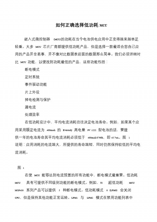
EM6819F2-B006 EM6819F2-B000 EM6819F2-A000 EM6819F2-B300 EM6819F4-B005
Pulse Width Modulation Analog to Digital Converter Operational Amplifier Power Check on start-up Voltage Level Detector In System Programming Sleep Counter Wake-Up
15MHz 15MHz 15MHz 15MHz 15MHz 15MHz 15MHz 15MHz 15MHz 15MHz 15MHz 15MHz 15MHz 15MHz 15MHz
RC 8kHz 2MHz 15MHz RC 8kHz 2MHz 15MHz Crystal 32kHz - 4Mhz RC 8kHz 2MHz 15MHz Crystal 32kHz - 4Mhz RC 8kHz 2MHz 15MHz Crystal 32kHz - 4Mhz RC 8kHz 2MHz 15MHz RC 8kHz 2MHz 15MHz RC 8kHz 2MHz 15MHz Crystal 32kHz - 4Mhz RC 8kHz 2MHz 15MHz Crystal 32kHz - 4Mhz RC 8kHz 2MHz 15MHz Crystal 32kHz - 4Mhz RC 8kHz 2MHz 15MHz Crystal 32kHz - 4Mhz RC 8kHz 2MHz 15MHz RC 8kHz 2MHz 15MHz Crystal 32kHz - 4Mhz RC 8kHz 2MHz 15MHz Crystal 32kHz - 4Mhz RC 8kHz 2MHz 15MHz Crystal 32kHz - 4Mhz RC 8kHz 2MHz 15MHz Crystal 32kHz - 4Mhz
4 4 4 4 4 4 4 4 4 4 4 4 4 4 4
4 4 4 4 4 4 4 4 4 4 4 4 4 4 4
8 8 6 4 4 8 8 8 6 8 8 8 8 6
-
PwrCk Brown-Out VLD PwrCk Brown-Out OPAMP VLD PwrCk Brown-Out OPAMP VLD PwrCk Brown-Out OPAMP VLD PwrCk Brown-Out OPAMP VLD PwrCk Brown-Out OPAMP VLD PwrCk Brown-Out OPAMP VLD PwrCk Brown-Out OPAMP VLD PwrCk Brown-Out OPAMP VLD PwrCk Brown-Out OPAMP VLD PwrCk Brown-Out OPAMP VLD PwrCk Brown-Out OPAMP VLD PwrCk Brown-Out OPAMP VLD PwrCk Brown-Out OPAMP VLD PwrCk Brown-Out OPAMP VLD
it Ti m er PW s M (u p 10 to bi ch tA an D Te C ne m (u l) p. p t S o A ch dd ens an or iti ne on l) al an al og
or d
B )
ic
tio n
s)
ve rt or pi ns
m un
W
da ta
-
4K word Flash (11.5kByte)
EM6819F4-A005 EM6819F4-A000 EM6819F4-B000 EM6819F4-B100 EM6819F4-B300 EM6819F6-B004
-
12 to 24 12 to 24 16 to 24 04 to 24 12 to 24
EM6819 Family ensures 0.9V Battery Operations and much more …
ld ig ita lf l w D rite eb ug for O so Pa f n ck C twa hi a N p re ot ge u /I e (s SP p d 1 ) se
2 2 2 2 4 4 4 4 4 4 6 6 6 6 6
4 4 4 4 8 8 8 8 8 8 12 12 12 12 8
256 512 512 512 256 256 512 512 512 512 512 512 512 512 512
0.9 - 3.6 0.9 - 3.6 0.9 - 3.6 1.8 - 5.5 0.9 - 3.6 0.9 - 3.6 0.9 - 3.6 0.9 - 3.6 1.8 - 3.6 1.8 - 5.5 0.9 - 3.6 0.9 - 3.6 1.8 - 3.6 1.8 - 3.6 1.8 - 5.5
Note 1 : Ask for package & volume availability
EM Microelectronic-Marin SA
January 2009
A
dd
ig i
A
C
iti o
N
ra
h
k
na
)
at e
Page 1
6K word Flash (16.9kByte)
EM6819F6-A000 EM6819F6-B100 EM6819F6-A100 EM6819F6-B300 NVM RAM GPIO SPI RC Crystal WD
-
12 to 24 12 to 24
-
16 to 24 PWM ADC OPAMP PwrCk VLD ISP SCWUP
-
04 to 12 12 to 24 12 to 20
-
16 to 24 04 to 12 08 to 12 12 to 24
SPI SW-UART / I2C SPI SW-UART / I2C SPI SW-UART / I2C SPI SW-UART / I2C SPI SW-UART / I2C SPI SW-UART / I2C SPI SW-UART / I2C SPI SW-UART / I2C SPI SW-UART / I2C SPI SW-UART / I2C SPI SW-UART / I2C SPI SW-UART / I2C SPI SW-UART / I2C SPI SW-UART / I2C SPI SW-UART / I2C
SO08 TSSOP16 TSSOP16-20-28 QFN20 TSSOP20-28 QFN20 TSSOP20-28 SO08 TSSOP16 TSSOP16-20 QFN20 TSSOP20-28 QFN20-32 TSSOP16-20-28 TSSOP16-20-28 QFN20 TSSOP20-28 SO08 TSSOP16-20-28 TSSOP20-28 QFN20-32 TSSOP16-20-28 TSSOP20-28 QFN20-32 TSSOP20-28
SCWUP WD SCWUP WD SCWUP WD SCWUP WD SCWUP WD SCWUP WD SCWUP WD SCWUP WD SCWUP WD SCWUP WD SCWUP WD SCWUP WD SCWUP WD SCWUP WD SCWUP WD
2K word Flash (5.6kByte)
Non Volatile Memory Random Access Memory General Purpose Input Output Serial Peripheral Interface Fully embedded RC Oscillator Oscillator on chip Digital Watch-dog