好盈HW25A HW30A说明书.doc2
好盈电调中文使用说明书
感谢您购买本产品!无刷动力系统功率强大,错误的使用可能造成人身伤害和设备损坏。
为此,我们强烈建议您在使用设备前仔细阅读本说明书,并严格遵守规定的操作程序。
我们不承担因使用本产品而引起的任何责任,包括但不限于对附带损失或间接损失的赔偿责任;同时,我们不承担因擅自对产品进行修改所引起的任何责任。
我们有权在不经通知的情况下变更产品设计、外观、性能及使用要求。
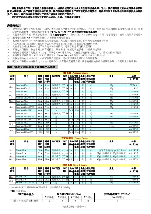
产品特色:✓全球首创“锂电平衡放电保护”功能,实时监测每个锂电单体的放电情况,一旦单体达到保护电压阈值即采取相应保护措施,有效防止电池组损坏,降低玩家消费支出(备注:仅“守护神”系列无刷电调具有本功能)✓首创开机奏乐功能,炫出您的个性。
(选配编程设定卡后,您可以从15首乐曲中任选一首写入电子调速器,也可以关闭奏乐功能)✓采用超低阻抗PCB(印刷线路板),具有极强的耐电流能力。
✓电源输入端采用日本名牌超低阻抗大容量电容,大大提升电源稳定性,同时对电池具有保护作用。
✓具备电压保护/过热保护/油门信号丢失保护等多重保护功能,有效延长电调使用寿命。
✓具有普通启动/柔和启动/超柔和启动三种启动模式,适用于固定翼飞机及直升机。
✓可设定油门行程,兼容市面上所有遥控器。
具备平滑、细腻的调速手感,一流的调速线性。
✓微处理器采用独立的稳压IC 供电,而不是从BEC输出取电,具有更好的抗干扰能力,大大降低失控的可能性。
✓最高转速可以达到210000 RPM(2极马达)、70000 RPM(6极马达)、35000 RPM(12极马达)。
✓具备完整的自主知识产权,产品可持续升级更新,用户更可以享受原厂软件升级服务。
✓配合小巧易携带的编程设定卡(注:选配件),具有简单直观的界面,使您随时随地修改各项编程参数。
(详见设定卡说明书)模型飞机用无刷电机电子调速器产品规格:接线示意图:锂电平衡放电监测保护接头示意图:各个厂家推出的锂电池配备有不同的平衡充电接口,因此我们提供了两种平衡放电监测保护接头供用户选用: 平衡放电监测保护接头(类型一): 平衡放电监测保护接头(类型二):适用于台湾亚拓等品牌锂电池 适用于Ployquest 、E-tec 、Thunder Pwer 等品牌锂电池产品功能简要说明:1. 刹车设定:无刹车/有刹车,出厂默认值为无刹车。
好盈海王电调说明书
好盈海王电调说明书1、将遥控器油门摇杆推至最低位置,接通遥控器电源。
2、将电池组接上无刷电子调速器,调速器开始自检,约2秒后电机发出“哔”长鸣音表示自检正常。
然后电机奏乐,表示一切准备就绪,等待您推动油门启动电机。
若无任何反应,请检查电池是否完好,电池连线是否可靠。
若上电后2秒电机发出“哔-哔-”的鸣音,5秒后又发出“56712”特殊提示音,表示电调进入编程设定模式,这说明您的遥控器未设置好,油门通道反向,请参考遥控器说明书正确设置油门通道的“正/反”向。
若上电后电机发出“哔-哔-、哔-哔-、哔-哔-”鸣音(间隔1秒),表示电池组电压过低或过高,请检查电池组电压。
3、若无任何反应,请检查电池是否完好,电池连线是否可靠。
若上电后2秒电机发出“哔-哔-”的鸣音,5秒后又发出特殊提示音,表示电调进入编程设定模式,这说明您的遥控器未设置好,油门通道反向,请参考遥控器说明书正确设置油门通道的“正/反”向。
若上电后电机发出“哔-哔-、哔-哔-、哔-哔-”鸣音(间隔1秒),表示电池组电压过低或过高,请检查电池组电压。
警示音说明:1、电压不正常警示音:电调开机时,会对电源电压进行检测,当电源电压不在正常范围内时,电调会作如下警示:“哔-哔-、哔-哔-、哔-哔-”(每两声之间的间隔时间为1秒),直到电源电压正常为止。
2、油门信号丢失警示音:当电调未检测到油门信号时,电调会作如下警示“哔-、哔-、哔-”(每声之间的间隔为2秒)。
3、油门未归零(油门摇杆未置于最低位置)警示音:当油门未打到最低时,电调会作如下警示:哔-哔-哔-哔-哔-(很急促的单音鸣叫)。
4、油门行程过小警示音:当所设定油门行程过窄时(电调设计时,要求油门行程不得小于三格油门),电调会做警示,本次行程设定无效,需重新设定。
警示方式为:哔-哔-哔-哔-哔-(很急促的单音鸣叫)。
Morningstar 25A 40A MPPT 太阳能充电器- 快速入门指南说明书

Scan QR Code to go directly to the ProStar MPPT Installation Manual and warranty information online.
Warning: Shock Hazard This unit is not provided with a GFDI device. This charge controller must be used with an external GFDI device as required by the Article 690 of the National Electrical Code for the installation location.
PC MeterBus Adapter (MSC)
1
ProStar MPPT™ Charge Controller
Caution: Equipment Damage
Do not expose the ProStar CC to weather. Locate in a dry, protected area to prevent equipment damage. Ensure the minimum clearance requirements are followed to provide adequate ventilation and prevent the unit from overheating.
Ferrite Chokes
Mounting Template
*A Menu Map is also included with metered versions, but is not shown in this guide.
OKW电子外壳和调节旋钮说明书

ENCLOSURES AND OPERATING ELEMENTS FOR MEASUREMENTTECHNOLOGY32OKW electronic enclosures and tuning knobs meet the exacting standards requiredfor precision measurement, automation and control.Smart, ergonomic enclosures with application-specific accessories offer usersf atigue-free viewing and operation. Robust construction protectsyour electronics – even in harsh environments.Benefits for users include enhanced product quality, greater productivity,energy savings, and seamless monitoring and documentation.MEASURING TECHNOLOGYDEPENDS ON PRECISIONCONTROL-KNOBSAward-winning CONTROL-KNOBS for rotaryp otentiometers or encoders with round shaft ends (DIN 41591). Suitable for rotary/click functions in menu-driven interfaces. Proven collet fixture system.Optional multi-colour illumination with energy-saving SMD LED technology.APPLICATIONSOKW solutions are ideal for a wide rangeof manual and automated measuring applications:▪ m easuring physical, electromagnetic, electrical and other variables▪ d ata loggers and tracking systems ▪ t est equipment and detectors▪ m onitoring and control, alarm and emergency systems ▪ w earables▪ s mart devices for IoT, IIoT and IoMT ▪ c alibration devices and systems.CARRYTECCARRYTEC (IP 54 optional) is a large portable enclosure witha robust integrated handle that is comfortable to hold. The operating area can accommodate user interfaces from 8.4“ (21 cm) to 13.4“ (34 cm). At the rear there are mounting points for a tripod or suspension arm. Accessories include side-mounted cases for probes, sensors and other equipment.SOLID-BOXRobust IP 66/IP 67 enclosures with IK 08 impact protection,a V-0 flammability rating, and a large user interface.Deep recesses protect connectors, enabling your electronics to deliverp recise data accurately and reliably – even in challenging environments.5Award-winning wearable enclosuresin a huge range of shapes, sizes and colours. Easy to wear/attach.INTELLIGENT ENCLOSURES FOR enclosures for modern control units. Comfortable to hold. Easy-clean glossy surface. Moulded from UV-stable ASA or infrared-permeable PMMA. IP 65 protection optional.EASYTECFlanged enclosures for rapidmounting on walls and tubes/round profiles. Ideal for modern sensor applications.MINI-DATA-BOXSmart sensor enclosures with/ without flanges for fast mounting on walls, ceilings, rails and tubes.CONNECTIdeal for wired applications as well as mobile devices with battery operation, e.g. for measuringi nstruments, test systems etc.SOFT-CASEWide-format contoured enclosures for handheld, tabletop or wall-mounted UNITECDual-face enclosures with sloping dialo-gue areas (72° and 18°) for face-to-face together perfectly, enabling complex workflows to be controlled and implemented Our customisation services include assembly of cable glands and grommets – so your enclosures arrive ready for the installation of your electronics.SMART-CONTROLWedge-shaped enclosures for easy installation in corners. They can also BODY-CASEComfortable enclosures for personal electronics worn on or close to the body.9Industrial electronic enclosures with high impact resistance (IK 08) and ingress protection (IP 66, SECURE AND RELIABLE FOR CONTROL-KNOBSNew ergonomic CONTROL-KNOBS have a soft-touch surface which is easy to grip and feels comfortable in operation. The high- quality appearance – illuminated if required –d istinguishes this advanced range of tuning knobs PROTECSquare control centre enclosures for desk and wall electronics. Ideal for touchscreens. Choose from three versions.DATEC-COMPACTHandheld enclosures with a high protection class and robust design. Ideal for mobile measuring applications either indoors or outdoors.Handheld enclosures with a largehead section for bigger display modules. Narrow holding area for greater user comfort.High ingress protection up to IP 65 (XS, S), IP 54 (M, L)MINI-DATA-BOXTough industrial plastic enclosures up to IP65 with flanges for fast mounting to walls, ceilings, rails, tubes or masts.IN-BOXImpact-resistant ABS (OK 07) or PC (IK 08) enclosures for industrial electronics. Rated IP 66, IP 67. Also available with transparent lid.EVOTECWide range of robust enclosures (IP 65 optional) for contemporary tabletop/desktop electronics. Available with/without sloping top.SMART-TERMINALRobust and elegant extrudedaluminium/plastic enclosures for large assemblies.Custom lengths are available.1011IN-BOX POTTING BOXES TOP-KNOBS RAILTEC B/C SMART-CONTROL HAND-TERMINAL SENSO-CASE CARRYTEC DATEC-CONTROL BODY-CASE INTERFACE-TERMINAL EVOTEC MINITEC SNAPTEC SHELL-TYPE CASES STYLE-CASE NET-BOX PROTEC SMART-CASE DIATEC SMART-TERMINAL ROBUST-BOX TUNING KNOBS ‘CLASSIC’STANDARD PRODUCT RANGETOPTEC SLIM-CASE CONNECT ERGO-CASE DATEC-POCKET-BOX DATEC-MOBIL-BOX DATEC-COMPACTSOFT-CASE COMTEC SOLID-BOX DATEC-TERMINAL FLAT-PACK CASE COM-KNOBS DESK CASES UNITECART-CASECOMBINATION KNOBS EASYTEC SYNERGY STAR-KNOBS CONTROL-KNOBSSMART-BOXSMART-PANELMINI-DATA-BOX MEDITEC 1213>>>FROM STANDARD View our comprehensive standard range and select the enclosure or tuning knob that best matches your ideas, your components and the needs of your customers. Next simply tell us what you need for your product.Together we will discuss the modifications needed, your quality requirements, the price and delivery time.MACHININGEMC SHIELDINGMATERIALSLACQUERINGPRINTINGDECOR FOILSLASER MARKINGINSTALLATION/ASSEMBLYTOI N D I V I DUA LI T Y1415“INDIVIDUAL COLOURS”On request we can also produce many of our enclosures and tuning knobs in special colours. To match the colour you require, we can have the natural plastic material coloured and extruded toa high standard. Individual colour adjustments are possiblea ccording to a sample, RAL or Pantone shades.“V-0”Manufacturing of enclosuresin flame-retardant (V-0) plastic on request.SPECIAL MATERIALProtect your electronics from external interference, as well as from increased internal emission noise. We coat the inside of the enclosure with a luminium to shield plastic parts (which offer no natural p rotectionagainst electromagnetic radiation).EMC SHIELDINGLaser marking is ideal for individual labelling,i dentifying or marking – especially for very smallm achine-readable markings such as QR codes,b arcodes and DataMatrix codes. Consecutiven umbering of parts and the addition of individual texts/logos is quick and easy.LASER MARKINGSpecify printing to give your products a personal touch, and to indicate function and usage. With precision craftsmanship, we can carry out the required printing to your satisfaction. Depending on the printing format and type of enclosure, we can offer youscreen printing, tampo printing as well as digital printing.PRINTINGWe can lacquer the enclosures and tuning knobs in any colour you wish to suit your application orc ompany branding. OKW offers a wide choice of lacquers. They include soft-touch, metallic effects and ESD conductive lacquer to prevent electrostatic discharges.LACQUERINGWe can perform individual machining processes for you, quickly and reliably, for sample or series productionq uantities. You will receive your enclosures ready for the installation of your electronics. Milling, tapping, engraving, drilling, countersinking and stamping – there is practically no limit to the variety of shapes and designs.MACHININGFor lettering and colour design, we can digitally print product labels quickly and easily for small batches s tarting with one unit. Digital printing enables co nsecutive numbering, codes and technicals pecifications. Colour graduations are also possible.DECOR FOILSWe assemble your enclosure accessories including cable glands, belt/pocket clips, tilt foot bars, wall-mount kits, hinges, carry handles, keyboard foils, product labels, type plates, display windows, mounting pillars, seals and fibre-optics. The service also includes packaging to your specifications.ASSEMBLY OF ACCESSORIESCUSTOMISINGOdenwälder Kunststoffwerke Gehäusesysteme GmbH Friedrich-List-Str. 374722 Buchen/Germany Tel. +49 (0) 62 81 | 404-00*****************Web Turtle © by OKW Gehäusesysteme,Buchen, Germany.Subject to technical modificationwithout notice.DPMES23e | September 2023YOUR PARTNER:ASK FOR A SAMPLE!It‘s quick and easy online - just go to the OKW website, add the required enclosure/tuning knob version by clicking “Add to my basket … and tick “Sample …. Then add your contact details and send off the form. You will receive a confirmation of your request by email, and your sample will be on its way.。
Maxim Hi-Wheel Plow BHW-24 产品说明书

Date Updated: 08/2016 Owners Guide Part Number: MBHW24B.MAXMaxim Hi‐Wheel PlowBHW – 24Owners GuideMaxim Manufacturing: Address: 20195 South Diamond Lake Rd. Suite 100Rogers, MN 55374Website: E-mail:******************Phone Number: (800) 621-2789Thank you for purchasing the Maxim Hi‐Wheel PlowProudly made in the USATools needed for Assembly:∙½” Wrench – (Quantity: 2)∙OR ½” Socket and ½” Wrench∙9/16 Wrench (Quantity: 2)Note:‐See page 3 for Parts List and Assembly Diagram‐See page 4 for Fastener IdentificationMaxim Hi ‐Wheel Plow Assembly InstructionsModel Number: BHW ‐24Step 1: Unpacking Wheel Plow BoxStep 2: Hex Bolt/Flat Washer through HandleStep 3: Plow Support Brace/WheelStep 4: Securing the Other Plow Support Brace/Handle1‐Remove all pieces from box and make sure you have all of the necessary parts. ‐Refer to the Parts List on page 3. ‐Locate a 3/8 x 5 1/2” bolt (Ref. #11) . Place one 3/8” flat washer (Ref. #8) on the bolt and insertthrough one of the handles (Ref. #1)‐Place one of the Plow Support Braces (Ref. #4) on the Bolt (Ref. #11), followed by the axle spacer (Ref. #5). ‐Slide bolt and axle spacer through the center of the Wheel (Ref. #6)‐Attach the other Plow Support Brace (Ref. #4), other Handle (Ref. #1), and 3/8” Flat Washer (Ref. #8) onto the bolt.‐Followed by the 3/8” NC Nylok Jam Nut (Ref. #18). Do Not Tighten . (Bolts will need to be somewhat loose for cross brace assembly)Step 5: Cross Brace Step 6: Lower Plow SupportsStep 7: Connect Lower/Plow Support BracesStep 8: Connect Remaining Lower Plow Support Holes21.)Locate a 5/16” x 1 ¾” Hex Bolt (Ref. #7)and place a 5/16” flat washer (Ref. #8) on the bolt, then put it through the handle (Ref. #1).2.) Place the Right Hand Lower Plow Support (Ref. #3A) on the bolt, followed by a 5/16” lock washer (Ref. #9) and 5/16” hex nut (Ref. #10)3.) Repeat the same steps for the Left Hand Lower Plow Support (Ref. #3B)on the left handle‐With a 5/16” x 1 ¼” Hex Bolt (Ref. #12), connect the Lower Plow Supports (Ref. #3A/3B) to the outside of the Plow Support Braces (Ref. #4). ‐Secure with 5/16” lock washer (Ref. #9) and 5/16” Hex Nut (Ref. #10).1.) Secure cross brace (Ref. #2) by placing a 5/16” flat washer (Ref. #8) on the 5/16” x 1 ¾” bolt (Ref. #7) and inserting it through the upper most hole on the handle (Ref. #1) and the screw hole of the cross brace.2.) Fasten with a 5/16” lock washer (Ref. #9) and 5/16” hex nut (Ref. #10)3.) Repeat same steps for the other handle‐Insert a 5/16” x 1 1/4” Hex bolt (Ref. #12) through each of the remaining Lower Plow Support holes.‐Add a 5/16” x 7/8” x .280 Spacer (Ref. #14) to each bolt. ‐Secure with a 5/16” lock washer (Ref. #9) and a 5/16” Hex Nut (Ref. #10).‐Tighten all nuts and bolts at this time.Step 9: Connecting the Plow’s Attachments3Reference # Required Part Number Description1 2 360410 (-S) Handles Pair (-S for Single Handle) 2 1 360411 Cross Brace3A 1 360412-R Lower Plow Support, RH 3B 1 360412-L Lower Plow Support, LH 4 2 360413 Plow Support Brace 5 1 360418 Axle Spacer 6 1 360414 24” S poke W heel 7 5 400208 5/16” x 1 3/4” H ex Bolt 8 6 4550415/16”Flat Washer 9 8 446136 5/16” L ock W asher 10 8 443106 5/16” H ex Nut 11 1 400286 3/8 x 5 1/2” Hex Bolt 12 3 400190 5/16” x 1 1/4” H ex Bolt 14 2 360419 5/16” x 7/8” x .280 Spacers 15 1 360416 Turn Shovel 16 1 360417 5-Finger Cultivator 17 1 360415 Double Point Shovel 18 1 800312 3/8” N C Nyloc Jam Nut 1924550423/8” Flat Washer‐To attach the Turn Shovel (Ref. #15), 5‐Finger Cultivator (Ref. #16), or the Double Pointed Shovel (Ref. #17): Place one 5/16” Flat washer (Ref. #8) onto a 5/16” x 1 ¾” hex bolt (Ref. #7) and insert through the hole in the attachment, then the opening between the spacers (Ref. #14) in the lower brace. Secure with a 5/16” flat washer (Ref. #8), 5/16” lock washer (Ref. #9), and a 5/16” hex nut (Ref. #10).BHW ‐24 Hi ‐Wheel Plow Parts List:*If you are missing any parts, please contact us at (800) 621‐2789*Maxim Hi‐Wheel Plow BHW‐24‐ Fastener Identification:*If you are missing any fasteners, please contact us at (800) 621‐2789*P4。
Powerheart AED G3 产品说明书

Rescue Ready® performance sets Powerheart AEDs apart Our Rescue Ready technology distinguishes us among competitors.+Every day, to ensure anytime functionality, the AED self checks all main components (battery, hardware, software, and pads). +Every week, the AED completes a partial charge of the high-voltage electronics. +Every month, the AED charges the high-voltage electronics to full energy.If anything is amiss, the Rescue Ready status indicator on the handle changes from green to red and the device will emit an audible alert to prompt the user to service the unit. In sum, a Powerheart AED is Rescue Ready when a life depends on it.In an emergency, Powerheart AEDs are easy to useWhen sudden cardiac arrest strikes, every second is critical. We designed our Powerheart AED G3 Automatic and G3 Semi-Automatic to help maximize responder efforts.+When the rescuer applies the pads, the device analyzes the heart rhythm and “knows” when to deliver (or not deliver) the shock.+On fully-automatic models the shock is delivered automatically, without requiring the user to press a shock button.+The text screen lends extra help in noisy and chaotic environments.The bottom line: These AEDs are easy to use for almost anyone with minimal training. For sudden cardiac arrest victims, a Powerheart AED – and you – may save a life.Variable escalating energyOur AED determines the electrical impedance (resistance level) of each patient and customizes the energy level delivered. If more than one shock is necessary, our proprietary STAR® biphasic software escalates the energy to deliver therapy at an appropriate, higher level.Appropriate Locations• Fire department vehicles• Medical transport• Police vehicles• Physician offices• General practitioner’soffices• Hospitals• Any public settingPrimary BenefitsReliability. Powerheart G3 AEDsare Rescue Ready®, meaningthey self-test daily to ensurethey work when you need them.Ease of use.• Clear voice prompts guidethe user through theentire process.• The device analyzes theheart rhythm and “knows”when to deliver (or not deliver)the shock.• The text screen provideshelpful information.Assurance. These Powerheart G3AEDs have a 7-year warranty anda 4-year full battery replacementguarantee.Cardiac Science Corporation • N7W22025JohnsonDrive,Waukesha,WI53186USA•+1.262.953.3500•UStoll-free+1.800.426.0337•Fax:+1.262.953.3499•*********************** Orders and Customer Care (US and International) • +1.262.953.3500 • US toll-free +1.800.426.0337 • Fax:+1.262.798.8292•***********************T echnical Support •(US)Fax:+1.262.798.5236•***********************************•(International)***************************************Cardiac Science International A/S • KirkeVaerloesevej14,DK-3500Vaerloese,Denmark•+45.4438.0500•Fax:+45.4438.0501•********************************United Kingdom • TheManse,39NorthendenRoad,Sale,Manchester,M332DH,UnitedKingdom•+44.161.926.0000•*********************France • T ech‘indusD,645rueMayordeMontricher,13854Aix-en-ProvenceCedex3,France•+33.4.42.12.37.91•*************************Italy•ViaGorra55,I-29122Piacenza,Italy•+39.0523.1901052•Fax:+39.0523.1885099•*************************Central Europe (D, A, CH) • Elisabeth T reskow-Platz1,50678Köln,Germany•+49.221.337745.90•********************************China • Room606,ZhongHuangBldg.,No.1007,ZhongShanNanErRoad,Shanghai200233,China•+86.21.3120.0832•************************ Cardiac Science, the Shielded Heart logo, Powerheart, Rescue Ready, STAR, Intellisense, MDLink, and Rescuelink are trademarks ofCardiac Science Corporation. Copyright © 2013 Cardiac Science Corporation. All Rights Reserved. MKT-11200-01rHAuthorized EU representative • MDSS GmbH, Schiffgraben 41, D-30175 Hannover, Germany0086。
浩瀚电器产品说明书

Table of ContentsTopic PageSafety Procedures (3)Warranty (4)Placement and Installation………….…………………...…5-10Electrical Connection (11)LED Display and Setup………………………….……...…12-13Loading Products and Testing Unit (14)Power Light & Reset Button (15)Maintenance (16)Troubleshooting……………………………………….......17-18Parts……..…………………………………………………19-20Brush Diagram (21)Alarm (22)PAGE2IMPORTANT SAFETY INSTRUCTIONSREAD ALL INSTRUCTIONS BEFORE USING THIS APPLIANCEWARNING: TO REDUCE THE RISK OF FIRE, ELECTRICAL SHOCK OR INJURY:Use only manufacturer’s options and attachments. – Do not spray near open flame. – Do not spray on electrical equipment. – If any disposal of product is necessary, adhere to all local, state and federal laws governing its disposal. – Avoid contact with skin and eyes. – Do not spray directly on plastic or vinyl surfaces.DANGER:This equipment incorporates parts such as switches, motors, or the like that tend to produce arcs or sparks which can cause an explosion. When located in gasoline dispensing and service stations, install and use at least 20 feet horizontally from the exterior enclosure of any pump and at least 18 inches above driveway or ground level.Safety Procedures MODEL SVSRPAGE 3Limited Warranty*FILL OUT YOUR WARRANTY CARD AND RETURN TO THE FACTORY TO REGISTER YOUR COMBO VAC.Fragramatics Mfg. Co., Inc. warrants this equipment against defects in workmanship and material and will remedy any defect according to the terms of this Limited Warranty .Fragramatics will repair or replace at its option, any defective parts or component(s) for a period of one (1) year from the date of purchase. This Limited Warranty extends to the original purchaser only.To make a request or claim for service under the terms of this warranty, the original purchaser must contact Fragramatics and provide the product serial number, a description of the problem (including some indication of the parts or components felt to be defective), and the date of purchase. No parts, components or the equipment should be returned without authorization from us.The original purchaser shall be responsible for all shipping charges. Any item authorized by Fragramatics for return under the terms of this Limited Warranty must be shipped prepaid, in the original shipping container or equivalent to Fragramatics or to a local service center as authorized and determined byFragramatics. The purchaser assumes the risk of loss or damage in transit. (Please refer to your owner’s manual or contact Fragramatics if you need further information about proper shipping procedures).REPLACEMENT OR REPAIR OF PARTS OR COMPONENTS IN ACCORDANCE WITH THE ABOVE LIMITED WARRANTY SHALL BE THE PURCHASER’S SOLE AND EXCLUSIVE REMEDY AGAINST FRAGRA*MATICS.This Limited Warranty does not cover equipment that has been damaged due to misuse, mis-application, attempted theft, vandalism, accident, connection to an improper voltage supply or as a result of modification by other than Fragramatics. Components such as filters, gaskets, electrical components, hose fabric, rubber, plastic parts, or similar items are subject to wear or consumption during normal operation and this normal disintegration is not covered by the Limited Warranty .Fragramatics makes no warranty concerning the compliance of the equipment with any local, state, or federal/national laws or regulations. The purchaser agrees to accept full responsibility for complying with such laws.THERE ARE NO WARRANTIES OTHER THAN THOSE ON THE FACE HEREOF DESCRIBED ABOVE AND THEY ARE IN LIEU OF ALL OTHER WARRANTIES WHETHER EXPRESSED OR IMPLIED, INCLUDING BUT NOT LIMITED TO THE IMPLIED WARRANTIES OF MERCHANTABILITY AND FITNESS FOR PARTICULAR PURPOSE.FRAGRAMATICS MFG. CO., INC. SHALL NOT BE LIABLE FOR INCIDENTAL, SPECIAL, OR CONSEQUENTIAL DAMAGES INCLUDING WITHOUT LIMITATION DAMAGES RESULTING FROM PERSONAL, BODILY INJURY OR DEATH OR DAMAGES TO OR LOSS OF USE OF PROPERTY.MODEL SVSRPAGE 4Proper PlacementConsider vehicle traffic, ease of access, weather protection and lighting to enhance vacuum serviceability and income. Refer to SAFETY INSTRUCTIONS sheet in this manual forrestrictions concerning placement of these units in gasoline dispensing locations and service stations. For vacuum island layouts, see next four (4) pages.Select and prepare a solid, level site for a concrete or similar base. Consult local codes for foundation requirements. Note: Although we recommend 24” base height above grade, 20” base height above surrounding surface provides minimum protection from typical bumper damage and 30” base height should be considered maximum, considering coin acceptor position.CAUTION ELECTRICAL SHOCK HAZARD – DISCONNECT POWER PRIOR TO BEGINNING ANY SERVICE OR INSTALLATION WORK. CONTACT A TRAINEDELECTRICIAN IF YOU ARE UNSURE OF THESE PROCEDURES.PAGE 5Vacuum Island LayoutPAGE6Island Base Layout1½”PAGE7Vacuum Island LayoutMODEL SVSRPAGE 8Vacuum Island FootprintMODEL SVSRPAGE 9J-Bolts (new construction only). Carefully locate 4 “J” bolts (not provided) while forming concrete or masonry base. The plywood shipping base can be used as a locating fixture for the “J” bolts while the concrete is formed. See illustration to the left.Anchors are used for existingconstruction only. Drill and install suitable masonry anchors toaccommodate a 3/8 inch lag screw. Check anchor supplier information for proper drill size. HINT: Use the plywood base as a template for drilling the anchoring pilot holes. See illustration to the left.Guide to Easy InstallationMODEL SVSRPAGE 10IMPORTANT SAFETY INSTRUCTIONS. READ ALL INSTRUCTIONS BEFORE USING APPLIANCE.Connect to electrical service. The two (2) motor unit requires a 25 amp breaker and #12 awg. The three (3) Motor unit requires a 30 amp breaker and #10 awg. Check local codes and requirements and refer to “ IMPORTANT SAFETY INSTRUCTIONS” sheet in this manual.CAUTION ELECTRICAL SHOCK HAZARD. DISCONNECT POWER PRIOR TO BEGINNING ANY SERVICE ORINSTALLATION WORK. GET ASSISTANCE IF YOU ARE UNSURE OF THESE PROCEDURES.Connect to properly grounded 30 amp, 120 VAC 60 Hz power source.Installation should only be performed by a qualified electrician.• The electrical power should be stubbed in under the 18” vacuum tank cylinder (refer to installation instructions).•Maintain approximately 2” of clearance from the edge of the vacuum cylinder. There is 4“ ofvertical clearance from the mounting surface to the underside of the vacuum.• Route the power cable through either of the holes in the vacuum tank wall, through the cabinet front to the electrical connection box.•The cable should be inserted through the grommet at the base of the junction box. Connect the three wires: black (power), white (common), and green (ground) to the corresponding leads found inside the box. Finally, replace both the clear plastic and metal cover. ∗THIS IS THE ONLY ELECTRICAL CONNECTION NECESSARY.Electrical ConnectionMODEL SVSRPAGE 11• This machine employs a dual-mode timer, which features a built-in L.E.D. digital displayassembly.• The dual mode of the timer is like two (2) timers running simultaneously. Theycommunicate with each other to inform the other of the monetary credit remaining and each switch between the two (2) timers results in a recomputation of time to allow the exact amount of time deserved by the customer.• Each mode of the dual-mode timer is programmable for COINS TO START and CYCLETIME. They are pre-programmed from the factory as follows, unless specified by customer:• Timer A: $0.75 (3 coins) to start for one and a half minutes (1 ½) of shampoo or spot remover.• Timer B: $0.75 (3 coins) to start for four (4) minutes of vacuum.• The display feature of these timers is of the scrolling message type and includes three (3)different programmable messages which are pre-programmed at the factory as follows:• Welcome Message: WELCOME TO OUR TURBO CARPET-CARE VACUUM.• Sales Message: SWITCH TO SPOT AT ANY TIME.• Exit Message: TRY SPOT REMOVER THEN VAC SPOT AWAY.• To change the factory program from what is listed above, it is necessary to purchase (orborrow) a Model VAC-999 programmer (next page).Standard LED DisplayMODEL SVSRPAGE 12•While message is scrolling (power on), plug in the VAC-999 controller (see illustration at right) and press “Edit” key to enter into the programming mode. The jack is located at the rear of the display timer at top center. See illustration at the right.•The timer will display “Total Coins”. This is theamount of coin pulses the timer has received since the last time that the “Total Coins” was zeroed. To zero, press the “Delete” key. To save, press the “Save” key. The unit will now display “Saved”.•After the timer has saved “Total Coins”, the display will now go to “Coins to Start”. This controls the vend price for the shampoo function. Use the “▲ “or “▼ “ key to change the amount of “Coins to Start”. Press the “Save” key to save your input. The display will confirm this by displaying “Saved”.• The timer now displays “Coins to Start B”. Follow the same procedure as Step 3 to set the vacuum operation of the unit.• The timer now displays ”Cycle Time”. To change thistime by 10 second intervals, press the “◄“ key. Then press the “▲ “ or “▼“ key to change the time. To change the time by one second intervals, press the “►“ key. Then press the “▲ “ or “▼“ key to change the time. To save the “Cycle Time”, press the “Save” key. The timer will confirm this by displaying “Saved”.• The timer now displays “Cycle Time B”. Follow the same procedure as Step 5 to set the vacuum operation of the unit.• The timer now asks about “Bonus Time” programming. Press the “N” (No) key, thereby leaving the bonus time as is recommended by the factory.• The timer will now prompt for “Last Coin Beep?” Change reply from “10 seconds” to “1 minute” or vice versa by pressing the “▲“ or “▼“ key. To save the desired “Last Coin Beep?” press the “Save” key.•The “Welcome Message” will now appear with the first character located in the center of the board. If the first character is a blank, use your “▲“ or “▼“ key. You have 36 places to put characters. A blank space counts as a character. To change characters, press the “▲“ or “▼“ key. To move the message left one space, press the “◄” key. To move the message right one space, press the “►“ key. To insert a character, press the “Insert “ key. To delete a character, press the “Delete” key. To save message, press “Save” key.• The “Sales Message” appears next. It also has 36-character capability. Follow the same procedure as Step 9 to program message. The first character in the Sales Message will connect to the end of the “Welcome Message”. • The “Exit Message” appears next. It also has 36-character capability. Follow the same procedure as Step 9 to program message. NOTE: The “Welcome Message” and “Sales Message” scroll on the timer all the time. The ”Exit Message” scrolls three times after the timer has timed out. •Disconnect the VAC-999. Programming is now complete.LED Timer SetupMODEL SVSRBottom view of L E DTop View of LED TimerPAGE 131. Place shampoo products into dispenser assuring that pick-up tube and weight extend to the bottom of the container. Place one gallon undiluted Spot Remover under Spot Remover pump (A). Place Summer Shampoo into polytank (C) by Shampoo pump (B). Check label of shampoo, since shampoo is available in both ready to use formula and a concentrated formula that you must dilute (5:1) with water. Polytank can be filled without removal from vacuum. Capacity appx. 1.8 gallons.2. Prime dispenser to fill the hose and tubing. This may require up to two vend cycles. The toggle switch on the wand must be switched on during the priming cycle to activate fluid pump and air valve. Operate dispenser until a constant flow is observed. Dispenser is now ready for normal operation. Using proper Fragra*Matics Summer Shampoo, the dispenser will produce 5 gallons of foam in one minute and 45 seconds.3. FOR WINTER OPERATION: When temperatures drop to 32 degrees, remove Summer Shampoo and Spot Remover from unit and purge both lines. Place Fragra*Matics Winter Shampoo under the Spot Remover pump and place both pick up tubes (both shampoo and spot remover) into product.4. If dispenser is allowed to run empty of shampoo during normal operation, repeat step 2 to return dispenser to operation.CAUTION: USE ONLY FRAGRA*MATICS CARPET PRODUCTS TO INSURE PROPER OPERATION OF EQUIPMENT AND LIMIT YOUR LIABILITY. Loading Products and Testing Unit MODELSVSRPAGE 14• CAUTION:maintenance .(A) 24 Volt Fuse (Yellow Light)This is an ABC-2 amp ceramic snap-in fuse. It fuses power to the Timer. Use exact replacement.(B) 120 Volt Fuse (Red Light)This is an ABC-5 amp ceramic snap-in fuse. It fuses the primary “Power In” to the transformer and to the air compressor. Use exact replacement.(C) 24 Volt Fuse (Green Light)This is an ABC-1/2 amp snap-in fuse. It fuses power to the Coin Mech. Use exact replacement.(D) 24 Volt Fuse (Green Light)This is an ABC-1/2 amp snap-in fuse. It fuses power to the Vacuum Horn. Use exact replacement.(E) Reset ButtonWhile unit is running, this button may be used to end the “test cycle”, (these quarters or tokens will not be counted). The reset button may also be used to restore timer display Operation following thunder storm activity.Power Light Indicator and Main Chair AssemblyMODEL SVSRPAGE 15General Maintenance:• Keep the outer appearance of the unit looking good by using a glass cleaner to clean the front door decal and lexan faceplate in front of visual display.• Apply a stainless steel polish to the cabinet to maintain the appearance.• Take care not to use abrasive cleaners or rags for these applications to avoid scratching the surfaces.*DO NOT USE STEEL WOOL OR OTHER FERROUS BRUSHES TO CLEAN STAINLESS STEEL SURFACES. • Check motor brushes for wear and replace as necessary. • If three (3) motor vacuum, order a special nozzle. •Inspect gaskets and replace with factory replacements.Daily/Weekly Maintenance:• Remove dirt & debris from vacuum. HINT: Consider ordering a debris catcher (VAC-067) from your distributor to simplify this process. • Empty & shake bags weekly.• Exchange bags and wash bi-monthly.• Check hand tools, as suction will be impaired if vacuum nozzle wears excessively.• Always make sure vacuum doors are closed.• Check hose for signs of wear, replace if excessive. • Test vacuum suction and airflow.• Suction Test: Place hand tightly over cuff – feel for “pull”.• Air Test: Hold cupped hand near hose inlet – feel for “breeze”.Maintenance – Exterior & VacuumMODEL SVSRPAGE 16Poor performance: Poor suction.Test by placing hand over end – feel for “pull”. With hose end sealed, use plastic bag or sheet to test for leaks at door opening. (Move sheet lightly past suspected areas, plastic will “stick” at leaks.) MAKE SURE VACUUM DOORS ARE SEALED. Poor airflow. Check for overfilled debris area or hose clog. Clean filters. Check wire mesh at base of vacuum motor for blockage. Check motors to be sure that both are working.Vending Problems: Coin jams. Check for “overfilled” coin box. Check for clearance of coin path to coin box (remove obstructions). Check“cradle” area of coin mechanism for severely bent coins. Check magnet for Canadian (magnetic) coins.Red light not lit on Either no power to Check Breaker in control room. Check Connections at side of power make- vacuum Island or power distribution point at vacuum island. up box. vacuum Island power not entering unit.Red light is lit but, Main Fuse Test fuse or replace fuse. (A voltmeter connected across fluorescent fuse reading voltage, proves that the fuse is bad.) lights (3) are notlightedFluorescent lights lit, 24 volt Fuse Test fuse or replace fuse. but timer not lit and coin mechanism not accepting.TroubleshootingMODEL SVSRP AGE 17Unit accepts coinsCall Fragra*Matics at 1-800-643-1547, and ask for but timer fails to customer service. give credit.Unit works onVacuum motors not Remove dome. With unit in cycle and in vacuum mode, shampoo but powered or both are check for appx. 26 VAC between pin #3 and pin #4 on not on vacuum. inoperative. solid state relay. If present: 1. Replace solid state relay and motor fuses. 2. Replace Vacuum motors.If vacuum continues to run when switch is moved to shampoo or spot remover mode- - Replace solid state relayUnit won’t foam:No air at brush in Follow the two black wires entering the cabinet from the handle. And pumps don’t hose. They terminate at terminal block “C”. Jump run (turn).(24V) terminals “A” & “B” at the same time. If air discharges from the brush while activated and foams. Replace brush toggle switch.Unit won’t foam. Air at brush. Pump Check chemical levels and clean strainers. Remove runs. Pump tube fittings (see ill. page 14) run unit and measure the output of product. The pump should produce appx. 1 ½ to 2 ounces per minute, if it does – problem is in hose & handle. If less than amount above- order new pump tube and roller.LED timer blank after Press reset button for a minimum of two (2) seconds.electrical activity (Thunderstorm)Other problems: How to get additional Call Fragra*Matics at 1-800-643-1574, and ask for Technical help. customer service. Please have serial number of thevacuum ready. Serial number plate is located at the base of the cabinet near the vacuum hose or inside on nameplate.Troubleshooting ContinuedMODEL SVSRPAGE 18VAC-001Decaled Vacuum Dome VAC-002 Vacuum Hose 2” x 15’VAC-003 Tamper Proof Wrench (Dome) VAC-004 Dome Bolt (5 Required) VAC-009 Vacuum Motor VAC-011 Vacuum Bag (4 Required) VAC-012 Vacuum Acceptor – Single Coin VAC-015 FV-3/SVSR Coin Box Only VAC-022 Coin Chute________________________________ VAC-023 Lock Block PlateVAC-025 Vacuum NozzleVAC-026 ABC 5 Amp Chair Fuse VAC-027 ABC 10 Amp Vacuum Motor Fuse VAC-032 Vacuum Door Gasket VAC-033 Vacuum Horn VAC-037 Polytank for SVSR VAC-044 Motor Brushes (Set of 2) VAC-048 Large LED Timer VAC-051 Vacuum Cuff VAC-056 SVSR Pick-up Tubing Complete VAC-058 FNM 30 Fuse (3 Motor) VAC-060 FNM 25 Fuse (2 Motor) VAC-066 Diverter Valve VAC-067 Debris Catcher-Poly VAC-071 Vacuum Hose Hanger W/ HardwareVAC-072 Jug Shelf __________________ VAC-073 L.E.D. Light Segment VAC-074 SVSR Toggle Switch VAC-075 SVSR Wand w/ Toggle Switch VAC-076 Brush w/ Gasket VAC-077 SVSR Hose & Brush Assy. Complete VAC-078 SVSR Wand & Brush Complete VAC-079 SVSR Foam Generator VAC-080 SVSR Hose Assembly Only VAC-081 Spot Remover Pump Tube VAC-082 Shampoo Pump Tube VAC-083 SVSR Tubings W/ WirePartsMODEL SVSRPAGE 19VAC-091 Abus Lock (coin box)VAC-098 Peristaltic Pump – Shampoo VAC-099 Peristaltic Pump – Spot Remover VAC-101 SVSR Brush Holder VAC-103 SVSR Instruction Plate VAC-113 Foam Generator Barbs (Set of 3) VAC-116 Compression Fitting VAC-117 Ferrules (Set of 2) VAC-121 Vacuum Door Latch & Hasp – Latchless Style VAC-122 Vacuum Door W/ Gasket – Latchless Style VAC-144 SVSR Selector Switch – MVAC-149 Latchless Latch _____________________________ VAC-150 Latchless Hasp______________________________ VAC-169 SS-11 C 5 Solid State Relay VAC-172 SVSR Main Power Unit – L.E.D. VAC-216 SVSR Dome Decals (4)_______________________ VAC-217 SVSR Door Decal___________________________VAC-218 SVSR Tank Decals (2)________________________ VAC-231 Circular Light & Bracket (dome)________________ VAC-233 Bracket only for Circular Light_________________ VAC-235 Circular Bulb (dome) ________________________ VAC-243 Medeco Lock (D-1 units) _____________________ VAC-244 Medeco Key (D-1 units) VAC-999 L.E.D. Controller____________________________ DOR-040 Van Lock__________________________________ DOR-041 Van Key___________________________________SHP-001 Winter Shampoo (Ready to Use)_________________ SHP-002 Summer Concentrate Shampoo (Dilute 5:1)________ SHP-003 Summer Shampoo (Ready to Use) ______________SHP-004 Spot Remover _______________________________Parts - ContinuedMODEL SVSRPAGE 20VSR Hose & Brush Assembly CompleteBrush DiagramMODEL SVSRHose & Brush Assembly Complete – VAC-077PAGE 21Burglar Alarm (optional, D-1 models only) Keyfob Idle Mode (Button 1) indicates that Alarm is ON but MODEL SVSR PAGE 22。
好威 HCA系列交流充电机用户手册说明书

User ManualAC ChargerHCA Series(7-22kW)V1.0-2022-10-20Copyright Statement User Manual V1.0-2022-10-20The information in this user manual is subject to change due to product updates or other reasons. This guide cannot replace the product labels or the safety precautions in the user manual unless otherwise specified. All descriptions in the manual are for guidance only.and other GoodWe trademarks are trademarks of GoodWe Company. All other trademarks or registered trademarks mentioned in this manual are owned by GoodWe Company.TrademarksNOTICENo part of this manual can be reproduced or transmitted to the public platform in any form or by any means without the prior written authorization of GoodWe.Copyright©GoodWe Technologies Co.,Ltd. 2022. All rights reserved.CONTENT User Manual V1.0-2022-10-20 CONTENT1 About This Manual (1)1.1 Applicable Model (1)1.2 Target Audience (1)1.3 Symbol Definition (2)1.4 Updates (2)2 Safety Precaution (3)2.1 General Safety (3)2.2 AC Charger Safety (3)2.3 Personnel Requirements (4)2.4 Declaration of Conformity (4)3 Product Introduction (5)3.1 Product Overview (5)3.2 Application Scenarios (6)3.3 Operating Status of the Charger (8)3.4 Functionality (9)3.5 Appearance (10)3.5.1 Parts Description (10)3.5.2 Dimension (11)3.5.3 Indicator Description (12)3.5.4 Nameplate (13)4 Check and Storage (14)4.1 Check Before Receiving (14)4.2 Deliverables (14)4.3 Storage (14)5 Installation (15)5.1 Installation Requirements (15)5.2 Installation (17)5.2.1 Moving the Charger (17)5.2.2 Installing the Charger (18)5.2.3 Installing the Charger (Column Mounting) (20)6 Electrical Connection (22)6.1 Safety Precaution (22)6.2 Connecting the RCD Cable (23)6.3 Connecting the AC Cable (25)7 Equipment Commissioning (28)7.1 Check Before Power ON (28)7.2 Power On (28)User Manual V1.0-2022-10-20CONTENT7.3 Charging EV (29)7.3.1 Online Charging via SEMS Portal App (29)7.3.2 Offline Charging Steps via SolarGo App (29)7.3.3 Plug And Charge (29)8 System Commissioning (30)8.1 Indicator (30)8.2 Setting and Checking Charger Information via SolarGo APP (installers) (30)8.3 Setting and Checking Charger Information via SEMS Portal (User) (30)9 Maintenance (31)9.1 Power Off the Charger (31)9.2 Dismantle the Charger (31)9.3 Discard the Charger (31)9.4 Routine Maintenance (31)9.5 Troubleshooting (32)10 Technical Parameters (34)User Manual V1.0-2022-10-2001 About This Manual1 About This ManualThis manual describes the product information, installation, electrical connection, commissioning, troubleshooting and maintenance of the charger. Read through this manual before installing and operating the product. All the installers and users have to be familiar with the product features, functions, and safety precautions. This manual is subject to update without notice. For more product details and latest documents, visit https:///.1.1 Applicable ModelThis manual applies to the listed chargers below: (Hereinafter referred to as HCA).• GW7K-HCA• GW11K-HCA• GW22K-HCA1.2 Target AudienceThis manual applies to trained and knowledgeable technical professionals only. The technical personnel has to be familiar with the product, local standards, and electric systems.01 About This ManualUser Manual V1.0-2022-10-201.3 Symbol Definition1.4 UpdatesThe latest document contains all the updates made in earlier issues.V1.0 2022-10-20• First IssueDifferent levels of warning messages in this manual are defined as follows:User Manual V1.0-2022-10-2002 Safety Precaution 2 Safety PrecautionPlease strictly follow these safety instructions in the user manual during the operation.2.2 AC Charger Safety02 Safety PrecautionUser Manual V1.0-2022-10-202.3 Personnel Requirements2.4 Declaration of ConformityThe product with wireless communication function sold in the British market meets the requirements of the following directives:• Radio Equipment Regulations 2017• The Restrictions of the use of Certain Hazardous Substances in Electrical and Electronic Equipment Regulations 2012 (S.I. 2012/3032)The product with wireless communication function sold in the European market meets the requirements of the following directives:• Radio Equipment Directive 2014/53/EU (RED)• Restrictions of Hazardous Substances Directive 2011/65/EU and (EU) 2015/863 (RoHS)EUUKUser Manual V1.0-2022-10-2003 Product Introduction 3 Product Introduction3.1 Product OverviewHCA series product is one AC household charger mainly for EV charging, with functions like charging protection, online monitoring, remote upgrading, and so on.ModelModel descriptionThis manual applies to the listed chargers below:• GW7K-HCA• GW11K-HCA•GW22K-HCA03 Product IntroductionUser Manual V1.0-2022-10-203.2 Application Scenarios Connected to Grid Utility Grid Utility MeterRCD Charger EV (Electric Vehicle)BatteryPower cable Signal cablePower cable Signal cableUser Manual V1.0-2022-10-2003 Product IntroductionPower cableSignal cableConnected to PV String and Batteries (Near Field Control)03 Product IntroductionUser Manual V1.0-2022-10-203.3 Operating Status of the ChargerCircuit DiagramBelow is the circuit diagram for HCA Charger:(Reserved) It is able to communicate with the inverters or smart meter via the RS485 communication port.For single phase AC charger and three phase AC charger, the input port is used to connect with single-phase three-wire power cable and three-phase five-wire power cable respectively.The output port is used to connect with the charging connector.Emergency Stop refers to the emergency stop button.Grid or AC Power SourceUser Manual V1.0-2022-10-2003 Product Introduction 3.4 FunctionalityApplicable for Diverse Scenarios• The charger can be used together with grid-tied or hybrid inverters to form a PV-Storage-Charging integrated ecological system.• The charger can be connected with grid.Remote ControlWhen the charger is on line, users can control it remotely via SEMS Portal app, and upgrade the firmware remotely via the device management platform.Easy to Use and Maintain• The charger supports operation via commands issued by APP remotely when it is on line. • The charger supports operation via Bluetooth connected to APP in a short distance when it is off line.• The charger supports charging EV directly under Plug And Charge mode.• Users can check the charger’s real-time status via its indicator.• Users can check the charger's fault and operating data via APP.Safe and Reliable• The ingress protection rating of the charger is IP65, and the ingress protection rating of the charging plug is IP55. With a high rating, the charger has excellent anti-dust and waterproof features and can be operated and maintained outdoors.• To protect the product and ensure a secure running status, the product is integrated with over voltage and under voltage protection, over load protection, short-circuit protection, leakage protection, grounding, over temperature protection, EMS protection and protection against lighting.03 Product IntroductionUser Manual V1.0-2022-10-203.5 Appearance3.5.1 Parts DescriptionUser Manual V1.0-2022-10-2003 Product Introduction 3.5.2 Dimension(Optional) Residual Current Device Distribution BoardRCD for GW11K-HCA & GW22K-HCA03 Product IntroductionUser Manual V1.0-2022-10-203.5.3 Indicator Description(Optional) Installation PostUser Manual V1.0-2022-10-2003 Product Introduction 3.5.4 NameplateThe nameplate is for reference only.04 Check and StorageUser Manual V1.0-2022-10-204 Check and Storage4.1 Check Before ReceivingCheck the following items before receiving the product.1. Check the outer packing box for damage, such as holes, cracks, deformation, and others signs of equipment damage. Do not unpack the package and contact the supplier as soon as possible if any damage is found.2. Check the charger model. If the charger model is not what you requested, do not unpack the product and contact the supplier.3. Check the deliverables for correct model, complete contents, and intact appearance. Contact the supplier as soon as possible if any damage is found.4.3 StorageIf the charger is not to be installed or used immediately, please ensure that the storage environment meets the following requirements:1. Do not unpack the outer package or throw the desiccant away.2. Store the charger in a clean place. Make sure the temperature and humidity are appropriate and no condensation.3. The height and direction of the stacking chargers should follow the instructions on the packing box.4. The chargers must be stacked with caution to prevent them from falling.5. If the charger has been long term stored, it should be checked by professionals before being put into use.4.2 DeliverablesUser Manual V1.0-2022-10-2005 Installation5 Installation5.1 Installation RequirementsInstallation Environment Requirements1. Do not install the equipment in a place near flammable, explosive, or corrosive materials.2. Do not install the equipment in a place that is easy to touch. High temperature exists when the equipment is working. Do not touch the surface to avoid burning.3. Avoid the water pipes and cables buried in the wall when drilling holes.4. Install the equipment in a sheltered place.5. The place to install the equipment shall be well-ventilated for heat radiation and large enough for operations.6. The equipment with a high ingress protection rating can be installed indoors or outdoors. The temperature and humidity at the installation site should be within the appropriate range.7. Install the equipment at a height that is convenient for operation and maintenance, electrical connections, and checking indicators and labels.8. The altitude to install the charger shall be lower than the maximum working altitude 2000m.9. Install the equipment away from electromagnetic interference.05 Installation User Manual V1.0-2022-10-20 Mounting Support Requirements• The mounting support shall be nonflammable and fireproof.• Install the charger on a surface that is solid enough to bear the charger weight. Installation Angle Requirements• It is recommended to install the charger vertically.• Do not install the charger upside down, forward tilt, back forward tilt, or horizontally.User Manual V1.0-2022-10-2005 InstallationThe following tools are recommended when installing the equipment. Use other auxiliary tools on site if necessary.Installation Tool Requirements5.2 Installation5.2.1 Moving the Charger05 InstallationUser Manual V1.0-2022-10-205.2.2 Installing the ChargerStep 1 Take the mounting plate from the charger.Step 2 Put the plate on the wall horizontally and mark positions for drilling holes.Step 3 Drill holes to 50mm in depth by using the hammer drill with 8mm in diameter.Step 4 Use the expansion bolts to fix the charger on the wall.Step 5 Install the charger on the mounting plate.Step 6 Tighten the nuts to secure the mounting plate and the charger, ensure the charger’s installation is reliable.User Manual V1.0-2022-10-2005 InstallationInstalling the Residual Current Device Distribution BoardStep 1: Put the distribution board on the wall horizontally and mark positions for drilling holes.Step 2: Drill holes using the hammer drill.Step 3: Use the expansion bolts to fix the distribution board on the wall.Type II Distribution BoardType I Distribution Board05 InstallationUser Manual V1.0-2022-10-20Step 1 Take the mounting plate from the charger.Step 2 Put the post on the ground vertically and mark positions for drilling holes. A cable pipe with a diameter of 60mm has to be embedded underground.Step 3 Drill holes to 75mm in depth by using the hammer drill with 14mm in diameter.Step 4 Run the embedded cable through the post.Step 5 Use the expansion bolts to fix the charger on the ground.Step 6 Install the mounting plate on the post.Step 7 Install the charger on the mounting plate.Step 8 Tighten the nuts to secure the mounting plate and the charger, and ensure the charger is installed reliably.5.2.3 Installing the Charger (Post Mounting)Installing the Charger561111User Manual V1.0-2022-10-2005 Installation06 Electrical ConnectionUser Manual V1.0-2022-10-206 Electrical Connection6.1 Safety PrecautionUser Manual V1.0-2022-10-2006 Electrical ConnectionWiring SpecificationsRCD SpecificationsStep 1 Prepare the AC cable.Step 2 Crimp the AC cable.Step 3 Run the AC cable and terminal through the distribution box.Step 4 Screw the AC terminal on the RCD.Step 5 Install the top cover of the RCD distribution box to prevent water or foreign matters.06 Electrical ConnectionUser Manual V1.0-2022-10-20Type I RCDUser Manual V1.0-2022-10-2006 Electrical Connection Type II RCD6.3 Connecting the AC CableStep 1 Prepare the AC cable.Step 2 Crimp the AC cable.Step 3 Insert the AC input cable into the AC terminals and tighten it.Step 4 Tignten the AC input terminal into the charger.06 Electrical ConnectionUser Manual V1.0-2022-10-20AC-1 ConnectorUser Manual V1.0-2022-10-2006 Electrical ConnectionAC-2 Connector07 Equipment CommissioningUser Manual V1.0-2022-10-207.2 Power OnTurn on the RCD between the charger and the grid.7 Equipment Commissioning7.1 Check Before Power ONConnected to PV String and BatteriesUtility Grid Utility Meter RCD ChargerStep 1 Turn on the AC and DC switches on the inverter side.Step 2 (Optional) Turn on the switches on the battery side.Step 3 Turn on the RCD.User Manual V1.0-2022-10-2007 Equipment Commissioning7.3 Charging EVStep 1 Plug the charging plug into EV charging port.Step 2 Open SEMS Portal App and connect with the charger via the App. Then tab Start Charging .Step 3 Check EV’s charging status via the App or the charger indicator.Step 4 Tab End Charging on the App and the charging ends.Step 5 Disconnect the charging plug and put its cap. Wrap the cable around the charger.Step 1 Plug the charging plug into EV charging port.Step 2 Open SolarGo App and connect with the charger via the App. Then tab Start Charging . Step 3 Check EV’s charging status via the App or the charger indicator.Step 4 Tab End Charging on the App and the charging ends.Step 5 Disconnect the charging plug and put its cap. Wrap the cable around the charger.Step 1 Plug the charging plug into EV charging port.Step 2 The charging begins automatically.Step 3 Check EV’s charging status via the charger indicator.Step 4 Put its cap after charging and wrap the cable around the charger.7.3.1 Online Charging via SEMS Portal App7.3.2 Offline Charging Steps via SolarGo App7.3.3 Plug And Charge08 System Commissioning User Manual V1.0-2022-10-208 System Commissioning8.1 IndicatorSolarGo App User Manual8.3 Setting and Checking Charger Information via SEMS Portal (User)SEMS Master User Manual8.2 Setting and Checking Charger Information via SolarGo APP (installers)SEMS Portal AppSolarGo App SEMS Portal is a monitoring platform used to control the charger and inverter monly used functions:• Check the working status of the charger remotely or nearly • Start or stop charging remotely or nearly • Check the charging recordsFor more details, refer to SEMS Portal User Manual. Scan the QR code or visit https:///Ftp/EN/Downloads/User%20Manual/GW_SEMS%20Portal-User%20Manual-EN.pdf to get the user manual.SolarGo is a smart phone application used to configure the charger. Commonly used functions:• Check the working status of the charger.• Check the charging records etc.For more details, refer to SolarGo User Manual. Scan the QR code or visit https:///Ftp/EN/Downloads/User%20Manual/GW_SolarGo_User%20Manual-EN.pdf to get the user manual.User Manual V1.0-2022-10-2009 Maintenance9 Maintenance9.1 Power Off the ChargerDisconnect the RCD between the charger and the grid/inverter.9.3 Discard the ChargerIf the charger cannot work anymore, dispose of it according to the local disposal requirements for electrical equipment waste. The charger cannot be disposed of together with household waste.9.2 Dismantle the ChargerStep 1 Disconnect all cables, including AC and communication cables.Step 2 Remove the charger from the mounting plate.Step 3 Remove the mounting plate.Step 4 Store the charger properly. If the charger needs to be used later, ensure that the storage conditions meet the requirements.9.4 Routine Maintenance09 MaintenanceUser Manual V1.0-2022-10-209.5 TroubleshootingThe charger shows in red when there is fault. Log into SEMS Portal App or PV Master App for detailed troubleshooting.Perform troubleshooting according to the following methods. Contact the After Sales Service if these methods do not work.Collect the information below before contacting the After Sales Service, so that the problems can be solved quickly.1. Charger information like serial number, software version, installation date, fault time, fault frequency, etc.2. Installation environment, including weather conditions, and so on. It is recommended to provide some photos and videos to assist in analyzing the problem.3. Utility grid situation.User Manual V1.0-2022-10-2009 MaintenanceUser Manual V1.0-2022-10-2010 Technical parameters*1: Ingress Protection Rating: Charging Plug IEC type 2 is IP55.GoodWe Technologies Co., Ltd.No. 90 Zijin Rd., New District, Suzhou, 215011, China ******************GoodWe WebsiteLocal Contacts。
萨摩格HW-B450全面用户手册说明书

Questo manuale d’istruzione è fornito da trovaprezzi.it. Scopri tutte le offerte per Samsung HW-B450 o cerca il tuo prodotto tra le migliori offerte di Home TheatreSAFETY INFORMATION SAFETY WARNINGSTO REDUCE THE RISK OF ELECTRIC SHOCK, DO NOT REMOVE THE COVER (OR BACK).NO USER-SERVICEABLE PARTS ARE INSIDE. REFER SERVICING TO QUALIFIED SERVICE PERSONNEL.WARNING•To reduce the risk of fire or electric shock, donot expose this appliance to rain or moisture.CAUTION•TO PREVENT ELECTRIC SHOCK, MATCH WIDEBLADE OF PLUG TO WIDE SLOT, FULLY INSERT.•This apparatus shall always be connected to aAC outlet with a protective groundingconnection.•To disconnect the apparatus from the mains,the plug must be pulled out from the mainssocket, therefore the mains plug shall bereadily operable.•Do not expose this apparatus to dripping orsplashing. Do not put objects filled withliquids, such as vases on the apparatus.•To turn this apparatus off completely, youmust pull the power plug out of the wallsocket. Consequently, the power plug mustbe easily and readily accessible at all times.ENG - 2PRECAUTIONS1. Ensure that the AC power supply in yourhouse complies with the powerrequirements listed on the identificationsticker located on the bottom of yourproduct. Install your product horizontally, ona suitable base (furniture), with enoughspace around it for ventilation (7~10 cm).Make sure the ventilation slots are notcovered. Do not place the unit on amplifiersor other equipment which may become hot.This unit is designed for continuous use. Tofully turn off the unit, disconnect the AC plug from the wall outlet. Unplug the unit if youintend to leave it unused for a long period oftime.2. During thunderstorms, disconnect the ACplug from the wall outlet. Voltage peaks dueto lightning could damage the unit.3. Do not expose the unit to direct sunlight orother heat sources. This could lead tooverheating and cause the unit tomalfunction.4. Protect the product from moisture (i.e.vases), and excess heat (e.g. a fireplace) orequipment creating strong magnetic orelectric fields. Unplug the power cable fromthe AC wall socket if the unit malfunctions.Your product is not intended for industrialuse. It is for personal use only. Condensationmay occur if your product has been stored incold temperatures. If transporting the unitduring the winter, wait approximately2 hours until the unit has reached roomtemperature before using.5. The battery used with this product containschemicals that are harmful to theenvironment. Do not dispose of the batteryin the general household trash. Do notexpose the battery to excess heat, directsunlight, or fire. Do not short circuit,disassemble, or overheat the battery.CAUTION : Danger of explosion if the battery is replaced incorrectly. Replace only with the same or equivalent type.ENG - 3CONTENTS01 Checking the Components 602 Product Overview 7Front Panel / Top Panel of the Soundbar------------------------- 7Bottom Panel of the Soundbar------------------------- 8 03 Using the Remote Control 9Inserting Batteries before using the Remote Control (AAA batteries X 2)------------------------- 9How to Use the Remote Control------------------------- 9Using the Hidden Buttons (Buttons with more than one function)------------------------- 13Output specifications for the different sound effect modes------------------------- 13Adjusting the Soundbar volume with a TV remote control------------------------- 14 04 Connecting the Soundbar 15Connecting Electrical Power------------------------- 15Connecting the Soundbar to the Subwoofer------------------------- 16Connecting the Samsung Wireless Rear Kit to your Soundbar------------------------- 18 05 Using a wired connection to the TV 19Connecting using an Optical Cable------------------------- 19 06 Using a wireless connection to the TV 20Connecting a TV via Bluetooth------------------------- 20ENG - 407 Connecting an External Device 22Connecting using an Optical Cable------------------------- 2208 Connecting a USB Storage Device 2309 Connecting a Mobile Device 25Connecting via Bluetooth------------------------- 25 10 Installing the Wall Mount 28Installation Precautions------------------------- 28Wallmount Components------------------------- 2811 Placing the Soundbar on a TV stand 3012 Software Update 31Update Procedure------------------------- 31If UPDATE is not displayed------------------------- 3213 Troubleshooting 3314 Licence 3415 Open Source Licence Notice 3516 Important Notes About Service 3517 Specifications and Guide 36Specifications------------------------- 36ENG - 501 CHECKING THE COMPONENTS•For more information about the power supply and power consumption, refer to the label attached to the product. (Label: Bottom of the Soundbar Main Unit)•To purchase additional components or optional cables, contact a Samsung Service Centre or Samsung Customer Care.•The appearance of the accessories may differ slightly from the illustrations above.•Design and specifications are subject to change without prior notice.ENG - 602 PRODUCT OVERVIEWFront Panel / Top Panel of the Soundbar(Selects the source input mode.To turn on(Source)•When you plug in the AC cord, the power button will begin working in 4 to 6 seconds.•When you turn on this unit, there will be a 4 to 5 second delay before it produces sound.•If you want to enjoy sound only from the Soundbar, you must turn off the TV’s speakers in the Audio Setup menu of your TV. Refer to the owner’s manual supplied with your TV.ENG - 7ENG - 803 USING THE REMOTE CONTROLInserting Batteries before using the Remote Control (AAA batteries X 2)Slide the back cover in the direction of the arrow until it is completely removed.position.WOOFER TONE CONTROLCH LEVELPress the indicated areas to select Up/Down/Left/Right. Press Up/Down/Left/Right on the button to select or set functions.RepeatUsing the Hidden Buttons (Buttons with more than one function)•The Samsung Wireless Rear Speaker Kit can be purchased separately. To purchase a Kit, contact the vendor you purchased the Soundbar from.Adjusting the Soundbar volume with a TV remote controlAdjust the Soundbar volume using the TV’s remote control.•This function can be used with IR remote controls only. Bluetooth remote controls (remotecontrols that require pairing) are not supported.•Set the TV speaker to External Speaker to use this function.•Manufacturers supporting this function:Samsung, VIZIO, LG, Sony, Sharp, PHILIPS, PANASONIC, TOSHIBA, Hisense, RCA1. Turn Off the Soundbar.2. Push up and hold the WOOFER button for 5 seconds.Each time you push the WOOFER button up and hold it for 5 seconds, the mode switches in the following order: “OFF-TV REMOTE” (Default mode), “SAMSUNG-TV REMOTE”, “ALL-TV REMOTE”.04 CONNECTING THE SOUNDBARConnecting Electrical PowerUse the power components to connect the Subwoofer and Soundbar to an electrical outlet in the following order:Connecting the Soundbar to the SubwooferWhen the subwoofer is connected, you can enjoy rich bass sound. Automatic connection between the Subwoofer and the SoundbarManually connecting the Subwoofer if automatic connection failsBefore performing the manual connection procedure below:•Check whether the power cables for the Soundbar and subwoofer are connected properly.•Make sure that the Soundbar is turned on.1. Press and hold ID SET on the rear of the subwoofer for at least 5 seconds.•The red indicator on the rear of the subwoofer turns off and the blue indicator blinks.Rear of Subwoofer2. Press and hold the Up button on the remote control for at least 5 seconds.•The ID SET message appears on the display of the Soundbar for a moment, and then itdisappears.NOTES•Do not connect the power cord of this product or your TV to a wall outlet until all connections between components are complete.•Before moving or installing this product, be sure to turn off the power and disconnect the power cord.•If the main unit is powered off, the wireless subwoofer will go into stand-by mode and theSTANDBY LED on the rear of the sub-woofer will turn red after blinking blue several times.•If you use a device that uses the same frequency (5.8GHz) as the Soundbar near the Soundbar, interference may cause some sound interruption.•The maximum transmission distance of the main unit’s wireless signal is about 10 m, but may vary depending on your operating environment. If a steel-concrete or metallic wall is between the main unit and the wireless subwoofer, the system may not operate at all because the wireless signal cannot penetrate metal.PRECAUTIONS•Wireless receiving antennas are built into the wireless subwoofer. Keep the unit away from water and moisture.•For optimal listening performance, make sure that the area around the wireless subwoofer and the Wireless Receiver Module (sold separately) is clear of any obstructions.Connecting the Samsung Wireless Rear Kit to your Soundbar Expand to true wireless surround sound by connecting the Samsung Wireless Rear Speaker Kit (SWA-9100S or SWA-9200S sold separately) to your Soundbar.For detailed information on connections, see the Samsung Wireless Rear Speaker Kit manual.Hear TV sound from your Soundbar through wired or wireless connections.•When the Soundbar is connected to selected Samsung TVs, the Soundbar can be controlled using the TV’s remote control.–This feature is supported by 2017 and later Samsung Smart TVs that support Bluetooth when you connect the Soundbar to the TV using an optical cable.–This function also allows you to use the TV menu to adjust the sound field and various settings as well as the volume and mute.Connecting using an Optical CableWhen the audio in a broadcast is encoded in Dolby Digital and the “Digital Output Audio Format” on your TV is set to PCM, we recommend that you change the setting to Dolby Digital. When the setting on the TV is changed, you will experience better sound quality. (The TV menu may use different words for Dolby Digital and PCM depending on the TV manufacturer.)1. Connect the DIGITAL AUDIO IN (OPTICAL) port on the Soundbar to the OPTICAL OUT port of theTV with a digital optical cable.2. Press the(Source) button on the top panel or remote control, and then select the “D.IN ” mode.Connecting a TV via BluetoothWhen a TV is connected using Bluetooth, you can hear stereo sound without the hassle of cabling.Press the (Source)” changes to “there is a connect record.b. When “BT READY” appears, press and hold the (Source) button on the top panel of theSoundbar for more than 5 seconds to display “BT PAIRING”.2. Select Bluetooth mode on the TV. (For more information, see the TV’s manual.)3. Select “[AV] Samsung Soundbar B4-Series” or “[ AV ]Soundbar B4-Series” from the list on TV’sscreen.An available Soundbar is indicated with “Need Pairing” or “Paired” on the TV’s Bluetooth device list. To connect the TV to the Soundbar, select the message, and then establish a connection.•When the TV is connected, [TV Name] → “BT” appears on the Soundbar’s front display.4. You can now hear TV sound from the Soundbar.If the Soundbar is not found by the TV•Connect the TV and Soundbar with an optical cable, and select the “D.IN” mode by pressing (Source) button on the top of the Soundbar. See if the audio output works normally, andproceed with the step 2 and 3.If the device fails to connect•If a previously connected Soundbar listing (e.g. “[AV] Samsung Soundbar B4-Series” or “[ AV ] Soundbar B4-Series”) appears in the list, delete it.•Then repeat steps 1 through 3.NOTE•After you have connected the Soundbar to your TV the first time, use the “BT READY” mode to reconnect.Disconnecting the Soundbar from the TVPress the (Source) button on the top panel or on the remote control and switch to any mode but “BT”.•Disconnecting takes time because the TV must receive a response from the Soundbar.(The time required may differ, depending on the TV model.)•To cancel the automatic Bluetooth connection between the Soundbar and TV, press the Left button on the remote control for 5 seconds with the Soundbar in “BT READY” status. (TV Connect On/Off) What is the difference between BT READY and BT PAIRING?•BT READY : In this mode, you can search for previously connected TVs or connect a previously connected mobile device to the Soundbar.•BT PAIRING : In this mode, you can connect a new device to the Soundbar. (Press the PAIR button on the remote control or press and hold the (Source) button on the top of the Soundbar formore than 5 seconds while the Soundbar is in “BT” mode.)NOTES•If asked for a PIN code when connecting a Bluetooth device, enter <0000>.•In Bluetooth connection mode, the Bluetooth connection will be lost if the distance between the Soundbar and the Bluetooth device exceeds 10 m.•The Soundbar automatically turns off after 18 minutes in the Ready state.•The Soundbar may not perform Bluetooth search or connection correctly under the following circumstances:–If there is a strong electrical field around the Soundbar.–If several Bluetooth devices are simultaneously paired with the Soundbar.–If the Bluetooth device is turned off, not in place, or malfunctions.•Electronic devices may cause radio interference. Devices that generate electromagnetic waves must be kept away from the Soundbar main unit - e.g., microwaves, wireless LAN devices, etc.07 CONNECTING AN EXTERNAL DEVICE Connect to an external device via a wired connection or Bluetooth connection to play the external device’s sound through the Soundbar.1. Connect DIGITAL AUDIO IN (OPTICAL) on the main unit to the OPTICAL OUT port of the SourceDevice using a digital optical cable.2. Select “D.IN” mode by pressing the (Source) button on the top panel or on the remote control.08 CONNECTING A USB STORAGE DEVICEConnect the USB device to the USB port on the bottom of the product.2. Press the(Source) button on the top panel or on the remote control, and then select “USB ”.3. “USB ” appears in the display screen.4. Play music files from the USB storage device through the Soundbar.•The Soundbar automatically turns off (Auto Power Down) if no USB device has been connected for more than 18 minutes.File Format Type Compatibility list•If there are too many folders (about 256) and files (about 999) stored on the USB device, it may take the Soundbar some time to access and play files.09 CONNECTING A MOBILE DEVICEConnecting via BluetoothWhen a mobile device is connected using Bluetooth, you can hear stereo sound without the hassle of cabling.Press the (Source)” changes to “there is a connect record.b. When “BT READY” appears, press and hold the (Source) button on the top panel of theSoundbar for more than 5 seconds to display “BT PAIRING”.2. On your device, select “[AV] Samsung Soundbar B4-Series” or “[ AV ]Soundbar B4-Series” fromthe list that appears.•When the Soundbar is connected to the Bluetooth device, [Bluetooth Device Name] → “BT”appears in the front display.3. Play music files from the device connected via Bluetooth through the Soundbar.If the device fails to connect•If a previously connected Soundbar listing (e.g. “[AV] Samsung Soundbar B4-Series” or “[ AV ]Soundbar B4-Series”) appears in the list, delete it.•Then repeat steps 1 and 2.NOTE•After you have connected the Soundbar to your mobile device the first time, use the “BT READY”mode to reconnect.What is the difference between BT READY and BT PAIRING?•BT READY : In this mode, you can search for previously connected TVs or connect a previously connected mobile device to the Soundbar.•BT PAIRING : In this mode, you can connect a new device to the Soundbar. (Press the PAIR button on the remote control or press and hold the (Source) button on the top of the Soundbar formore than 5 seconds while the Soundbar is in “BT” mode.)NOTES•If asked for a PIN code when connecting a Bluetooth device, enter <0000>.•In Bluetooth connection mode, the Bluetooth connection will be lost if the distance between the Soundbar and the Bluetooth device exceeds 10 m.•The Soundbar automatically turns off after 18 minutes in the Ready state.•The Soundbar may not perform Bluetooth search or connection correctly under the following circumstances:–If there is a strong electrical field around the Soundbar.–If several Bluetooth devices are simultaneously paired with the Soundbar.–If the Bluetooth device is turned off, not in place, or malfunctions.•Electronic devices may cause radio interference. Devices that generate electromagnetic waves must be kept away from the Soundbar main unit - e.g., microwaves, wireless LAN devices, etc.•The Soundbar supports SBC data (44.1kHz, 48kHz).•Connect only to a Bluetooth device that supports the A2DP (AV) function.•You cannot connect the Soundbar to a Bluetooth device that supports only the HF (Hands Free) function.•Once you have paired the Soundbar to a Bluetooth device, selecting “[AV] Samsung Soundbar B4-Series” or “[ AV ]Soundbar B4-Series” from the device’s scanned devices list will automatically change the Soundbar to “BT” mode.–Available only if the Soundbar is listed among the Bluetooth device’s paired devices.(The Bluetooth device and the Soundbar must have been previously paired at least once.)•The Soundbar will appear in the Bluetooth device’s searched devices list only when the Soundbar is displaying “BT READY”.•The Soundbar cannot be paired to another Bluetooth device if already in Bluetooth mode and paired to a Bluetooth device.Bluetooth Power On (SOUND MODE)If a previously paired Bluetooth device tries to pair with the Soundbar when the Bluetooth Power On function is on and the Soundbar is turned off, the Soundbar turns on automatically.1. Press and hold the SOUND MODE button for more than 5 seconds on the remote while theSoundbar is turned on.2. “ON-BLUETOOTH POWER” appears on the Soundbar’s display.Disconnecting the Bluetooth device from a SoundbarYou can disconnect a Bluetooth device from the Soundbar. For instructions, see the Bluetooth device’s user manual.•The Soundbar will be disconnected.•When the Soundbar is disconnected from the Bluetooth device, the Soundbar will display“BT DISCONNECTED” on the front display.Disconnecting the Soundbar from the Bluetooth devicePress the (Source) button on the top panel or on the remote control, and then change to any modeexcept “BT”.•Disconnecting takes time because the Bluetooth device must receive a response from theSoundbar. (Disconnection time may differ, depending on the Bluetooth device)•When the Soundbar is disconnected from the Bluetooth device, the Soundbar will display“BT DISCONNECTED” on the front display.NOTES•In Bluetooth connection mode, the Bluetooth connection will be lost if the distance between the Soundbar and the Bluetooth device exceeds 10 m.•The Soundbar automatically turns off after 18 minutes in the Ready state.More About BluetoothBluetooth is a technology that enables Bluetooth-compliant devices to interconnect easily with each other using a short wireless connection.•A Bluetooth device may cause noise or malfunction, depending on usage, if:– A part of your body is in contact with the receiving/transmitting system of the Bluetooth device or the Soundbar.–It is subject to electrical variation from obstructions caused by a wall, corner, or office partition.–It is exposed to electrical interference from same frequency-band devices including medical equipment, microwave ovens, and wireless LANs.•Pair the Soundbar with the Bluetooth device while they are close together.•The further the distance between the Soundbar and Bluetooth device, the worse the quality is.If the distance exceeds the Bluetooth operational range, the connection is lost.•In poor reception areas, the Bluetooth connection may not work properly.•The Bluetooth connection only works when it is close to the unit. The connection will beautomatically cut off if the Bluetooth device is out of range. Even within range, the sound quality may be degraded by obstacles such as walls or doors.•This wireless device may cause electric interference during its operation.10 INSTALLING THEWALL MOUNTInstallation Precautions•Install on a vertical wall only.•Do not install in a place with hightemperature or humidity.•Verify whether the wall is strong enough tosupport the product’s weight. If not, reinforce the wall or choose another installation point.•Purchase and use the fixing screws oranchors appropriate for the kind of wall youhave (plaster board, iron board, wood, etc.). Ifpossible, fix the support screws into wallstuds.•Purchase wall mounting screws according tothe type and thickness of the wall you want to mount the Soundbar on.–Diameter: M5–Length: 35 mm or longer recommended.•Connect cables from the unit to externaldevices before you install the Soundbar onthe wall.•Make sure the unit is turned off andunplugged from the power source before you install it. Otherwise, it may cause an electricshock.Wallmount Components1. Place the Wall Mount Guide against the wallsurface.•The Wall Mount Guide must be level.•If your TV is mounted on the wall, installthe Soundbar at least 5 cm below the TV.2. Align the Wall Mount Guide’s Centre Line with the centre of your TV (if you are mounting the Soundbar below your TV), andanchors, make sure the holes you drill are large enough for the anchors you use.5. Push a screw (not supplied) through each Holder-Screw , and then screw each screw firmly into a support screw hole.Right end of Soundbar7. Install the Soundbar with the attached Bracket-Wall Mounts by hanging the Bracket-Wall Mounts on the Holder-Screws on the wall.11 PLACING THESOUNDBAR ON A NOTE•Make sure the Soundbar is placed on a flat and solid surface.12 SOFTWAREUPDATEfirmware by connecting a USB device with the firmware update stored on it to the USB port on your Soundbar. For more information about how to download update files, go to the Samsung Electronics website at ♑Support.Then, select the product type or enter the model number of your Soundbar, select the Software & Apps option, and then Downloads. Note that the option names can vary.Update ProcedureImportant: The update function erases all user settings. We recommend you write down your settings so that you can easily reset them after ✂ select Enter Model 3. Save the downloaded software to a USB stick and select “Extract Here” to unzip the folder.4. Turn off the Soundbar and connect the USB stick containing the software update to the USB port.5. Turn on the Soundbar and change the source to “USB ” mode. Within 3 minutes, “UPDATE ” is displayed and the update begins.6. When the update is complete, the Soundbar turns off. Turn on the Soundbar and then press the(Volume) button on the toppanel for 5 seconds. “INIT OK ” appears on the display and the Soundbar is reset.•This product has a DUAL BOOT function. If the firmware fails to update, you can update the firmware again. Soundbar AC code on when USB in with update file. Then update again but VFD no show anything, It will update finish after 2min.7. Restore your settings on the Soundbar.If UPDATE is not displayed1. Turn off the Soundbar, disconnect and thenreconnect the USB storage device thatcontains the update files to the Soundbar’sUSB port.2. Disconnect the Soundbar’s power cord,reconnect it, and then turn on the Soundbar. NOTES•The firmware update may not work properlyif audio files supported by the Soundbar arestored in the USB storage device.•Do not disconnect the power or remove theUSB device while updates are being applied.•After the update is completed, the user setup in the Soundbar is initialised so you can resetyour settings. We recommend you writedown your settings so that you can easilyreset them after the update. Note thatupdating firmware resets the subwooferconnection too.If the connection to the subwoofer is notre-established automatically after theupdate, refer to page 16.If the software update fails, check if the USBstick is defective.•Mac OS users should use MS-DOS (FAT) as the USB format.•Updating via USB may not be available,depending on the USB storage devicemanufacturer.13 TROUBLESHOOTINGBefore seeking assistance, check the following.;The volume of the Soundbar is too low or muted. Adjust the volume.;When any external device (STB, Bluetooth device, mobile device, etc.) is connected,adjust the volume of the external device. ;For sound output of the TV, selectSoundbar. (Samsung TV: Home ( ) →Menu → Settings ( ) → All Settings ( )→ Sound → Sound Output → SelectSoundbar);The cable connection to the Soundbar may not be loose. Remove the cable andconnect again.;Remove the power cord completely, reconnect, and turn the power on.;Reset the product and try again.(See page 31.);Disconnect the power cord of the Soundbar completely and reconnect, and then trysearching again. (See page 20.);Connect the TV and Soundbar with anoptical cable, and select the “D.IN” mode by pressing the (Source) button on thetop of the Soundbar. See if the audio output works normally, and try searching again.(See page 20.)button on the remote control orpress the (Source)for at least 5 seconds.)If the Soundbar is connected to anotherdevice, disconnect that device first toswitch the device.;When you turn off the Soundbar while watching TV, power synchronization with the TV is disabled. First turn off the TV. 14 LICENCEare trademarks of Dolby Laboratories Licensing Corporation. Manufactured under license from Dolby Laboratories. Confidential unpublished works. Copyright 1992-2019 Dolby Laboratories. All rights reserved.For DTS patents, see . Manufactured under license from DTS Licensing Limited. DTS, the Symbol, DTS in combination with the Symbol, and DTS 2.0 Channel are registered trademarks or trademarks of DTS, Inc. in the United States and/or other countries. © DTS, Inc. All Rights Reserved.The Bluetooth® word mark and logos are registered trademarks owned by Bluetooth SIG, Inc. and any use of such marks by Samsung Electronics Co., Ltd. is under license. Other trademarks and trade names are those of their respective owners.[ENERGY STAR]ENERGY STAR qualified model only–Your Samsung product is ENERGY STAR qualified in its factory default setting.Change to certain features, settings andfunctionality in this product can change the power consumption, possibly beyond thelimits required for ENERGY STARqualification.–Environmental Protection Agency and Department of Energy. ENERGY STAR is ajoint program of the Government agencies, designed to promote energy efficientproducts and practices.Refer to for more information of the ENERGY STAR Program. ENERGY STAR qualified model only (Applicable to Thin Client models only)As an ENERGY STAR® Partner, SAMSUNG has determined that this product meets the ENERGY STAR® guidelines for energy efficiency.–The ENERGY STAR Program has been to reduced greenhouse gas emissions andsave energy through voluntary labeling.–Power management setting of this product have been enabled by default, and havevarious timing setting from 1 minutes to 5hours.–The product can wake with a button press on the chassis from sleep mode. ENERGY STAR qualified model only (The other models)–As an ENERGY STAR Partner, Samsung has determined that this product or productmodels meets the ENERGY STAR guideline for energy efficiency.15 OPEN SOURCELICENCE NOTICETo send inquiries and requests for questions regarding open sources, contact Samsung Open Source ()16 IMPORTANTNOTES ABOUTSERVICEFigures and illustrations in this User Manual are provided for reference only and may differ from actual product appearance.。
LG WAW325H0GB 自动洗衣机说明书

Serie | 8, Washing machine, front loader, 9 kg, 1600 rpmWAW325H0GBOptional accessoriesWMZ2200 : Floor securing componentWMZ2381 : Extension for cold water inlet /AquastopEnjoy this supremely quiet and reliableappliance. Control your washing machinefrom anywhere with Home Connect via thesmartphone or tablet PC app.AutoStain: removes the four most common stains.Home Connect: home appliances with smart connectivity foran easier everyday life.EcoSilence Drive™: extremely energy-efficient and quiet inoperation with a 10-year warranty.AllergyPlus: specially developed for the needs of allergysufferers and sensitive skin.SpeedPerfect: perfectly clean in up to 65% less time.Technical DataConstruction type : Free-standingHeight of removable worktop (mm) : 850Dimensions of the product (mm) : 848 x 598 x 590Height for building under : 850.00Net weight (kg) : 79.774Connection rating (W) : 2300Current (A) : 10Voltage (V) : 220-240Frequency (Hz) : 50Approval certificates : CE, VDELength of electrical supply cord (cm) : 160Washing performance class : ADoor hinge : LeftWheels : NoPower consumption standby/network: Please check the usermanual for how to switch off the WiFi module. : 0.9Time auto-standby/network : 20.0EAN code : 4242005074907Capacity cotton (kg) - NEW (2010/30/EC) : 9.0Energy consumption annual (kWh/annum) - NEW (2010/30/EC) :152.00Power consumption in off-mode (W) - NEW (2010/30/EC) : 0.12Power consumption in left-on mode (W) - NEW (2010/30/EC) :0.43Water consumption annual (l/annum) - NEW (2010/30/EC) :11220Spin drying performance class : AMaximum spin speed (rpm) - NEW (2010/30/EC) : 1556Average washing time cotton 40C (partial load) - NEW (2010/30/EC) : 285Average washing time cotton 60C (full load) (min) - NEW(2010/30/EC) : 285Average washing time cotton 60C (partial load) - NEW (2010/30/EC) : 285: 20Noise level washing (dB(A) re 1 pW) : 47Noise level spinning (dB(A) re 1 pW) : 73Installation type : Free-standing'!2E20A F-a h e j a h!1/3Serie | 8, Washing machine, front loader, 9kg, 1600 rpm WAW325H0GBEnjoy this supremely quiet and reliable appliance. Control your washing machine from anywhere with Home Connect via the smartphone or tablet PC app.Performance-Energy Efficiency Class: A+++-Capacity: 9 kg-Maximum spin speed: 1600 rpm**-A spin class-Energy consumption :Weighted p.a. E-Consump. EU: 152 kWhkWh per year, based on 220 standard washing cycles --30% more economical (152kWh/year) than the standard value (217 kWh/year) of energy efficiency class A+++-Energy consumption: standard 60 °C cotton programme0.92 kWh full load and 0.6 kWh partial load and 40 °C cotton programme 0.42 kWh partial load-Cottons 60 Eco and Cottons 40 Eco are the standard washingprogrammes to which the information in the label relates.These programmes are suitable to clean normally soiledcotton laundry and are the most efficient programmes in terms of combined energy and water consumption.-Weighted power consumption off-mode / left-on mode: 0.12W / 0.43 W-Left-on Mode Duration: 20 min-Water consumption 11220 litres per year, based on 220standard washing cycles-Programme time:60 °C cotton programme 285 min at full load285 min at partial load and 40 °C cotton programme 285 min partial load-Drum volume: 65 litres-Noise level washing : 47dB (A) re 1pW: Noise levelspinning:73dB (A) re 1 pW Programmes/functions-Touch control: start/pause with reload function, Prewash,Spin speed reduction, Aqua Plus option for best rinsingresults, Temperature selection, stain selection, Remote Start,SpeedPerfect, EcoPerfect and 24 h, Ready in-Special programmes: Easy-Care, Night Wash, Shirts,Sportswear, Super Quick 15, Mixed Load, Allergy +, Duvet,Drum clean with reminder, rinse/spin/drain, Wool/Handwash,Delicate/Silk programme, Delicate / Silk -Safeguard monitoring system adjusts load distribution andprogramme settings to protect clothesKey features-Home Connect: Remote Monitoring and Control -Fully electronic control dial for wash programmes,temperature and special progammmes -EcoBar Plus function: five possible levels of energy and water consumption-AutoStain Removal System with 4 stain options - actionedwith standard programmes -VarioPerfect: speed or energy efficiency with perfect wash performance every time-ActiveWater: water management system -EcoSilence drive with 10 year warranty-AntiVibration Design - for more stability and quietness-Reload function: Flexibility in adding laundry items into thedrum, even after the wash cycle has started.Additional features-Large LCD display for programme status indication,temperature selection, max. spin speed, remaining time and 24 hours end time delay, stain selection and consumption indication-WaveDrum: gentle and efficient washing-3D AquaSpa wash system with cascade for faster waterpenetration-Drum clean with reminder function -Drum interior light -Reload facility-Detergent dispensing: easy clean -Divider for Liquid Detergent-Flow-through sensor for optimum water use -Multiple Water Protection-Continuous automatic load adjustment system -Overdosage indication -Foam detection system -Child lock-Buzzer to indicate the end of cycleTechnical Information-Dimensions (H X W X D): 84.8 x 59.8 x 63.2 cm -Slide-under installation-Large chrome, white door with 171° opening and 32cmporthole opening ** Values are rounded.2/3Serie | 8, Washing machine, front loader, 9kg, 1600 rpmWAW325H0GB3/3。
MG-301 120V, 25a 温泉浴缸安装和使用手册说明书

INSTALLATION AND OPERATION MANUALWarning!Use this unit only for its intended purposes or as described in this manual. Use only attachments recommended by the manufacturer.Risk of hyperthermia and possible drawing. Water temperature in excess of 38°C may be injurious to your health.Check and adjust temperature before use.READ AND FOLLOW ALL INSTRUCTIONSUNPACKING THE UNIT1.Inspect the carton, if carton damage is noted: take a picture if possible, notify the deliverer.2.NEVER LIFT THE TUB BY THE PLUMBING. Doing so can result in leaks, for which the installer is responsible.3.Immediately inspect the unit for damage even if there is no carton damage. Once the unit is installed surfacedamages will be assumed to be installation related if not reported at this point. Installers are responsible fordamage that occurs once the unit is placed in its niche.4.Inspect the plumbing for any loose fittings.5.Remove all packaging material except for the protective plastic. This has been placed on the tub at the factory toeliminate abrasions from handling. This should only be removed at final clean up.TESTING YOUR TUB BEFORE INSTALLATION1.All Tubs are 100% water tested at the factory and certified to be free of leaks. Transportation and mishandling maycause leaks. It is necessary to test the bath while there is access to all sides of the bath.2.This unit should be both static and operationally tested with water. It is best to test the unit outside by filling with agarden hose.a.Place the tub on a completely flat surface in an area where it may be drained after testing.b.Seal the drain (can be sealed with tape for test) and fill the tub three inches about the jets or to a normallevel if it’s a soaking tub.c.Allow the water to stand in tub for 10 minutes and then inspect all pluming and seals for leaks.ing an extension cord, operate each pump (air and hydro system if applicable) for 10 minutes andinspect for leaks. Inspect the unions around the pump; if leaks persist from the units after tightening;loosen the unions and insure that the 0-ring is seated properly.e.Insure all jets are open and working (every hydro jet is adjustable for both flow rate and direction of flow,depending on the jet, the water flow is adjustable by either turning the outside ring or the nozzle clockwiseand counter clockwise).NOTEThe flexible drain hose included with this unit is for installation into a floor drain only. Substituting the existing drain setup for a setup of the installer’s choice will not void the warranty of the unit as long as there is no evidence of misuse or damage to the tub. Call the manufactured for updated drain infoNOTE: IF the pumps do not operate:a.Check the breaker to insure power is on and the cable connecting the controls to the pump is attachedb.If an optional heater is present, check the indicator light on the heater to insure that power is present.Do not run any pumps or heaters unless the tub is filled with water to proper level. Damage due to dry running pumps is not coved under 3 year warranty.Failure to perform these tests before installation will make the installer liable for future repair costs. INSTALLATION PREPARATION1.Check the floor area where the tub is to be installeda.Clean area of any debris or trashe a 5 or 6-foot level and determine if the floor is leveled. If the floor is not leveled, adjust all 5 levelingfeet to perfectly level the tub. Note: it is important that all 5 leveling feet are completely touching the floorand level for the door system to work properly.2.Check to insure that the drain rough has been placed at the proper location. See spec sheets attached to your unit.3.Insure that the proper electrical service has been installed at the pump location. See electrical requirements below. ELECTRICAL REQUIREMENTSEquipment utilized on these baths requires individual dedicated electrical service for each product. Each service must be a dedicated 20 amp, 120 volt service that is GFCI protected.1.Hydro Jet Massage Systems require one 8.5 amp, 120 volt service that is GFCI protected.2.In-Line Heater System requires one 12.5amp, 120V service that is GFCI protected.ELECTRICAL INSTALLATIONAll electrical connections must be carried out by a certified electrician in accordance with local electrical requirements and codes.1. 2.Do not use abrasive cleaners as they will scratch and dull the surface of the acrylic.Plaster can be removed using a wooden stick. DO NOT use a metal scraper, wire brushes or water barrier wallboard or。
华文电动工程HobbywingPUMP HW-SMC907-DUL_20210710用户手册说明书
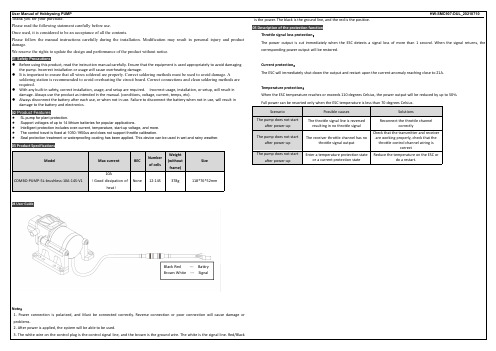
03 Product Specifications
Model COΒιβλιοθήκη BO-PUMP-5L-brushless-10A-14S-V1
Max current
BEC
10A (Good dissipation of
heat)
None
Number of cells
12-14S
Weight (without frame)
Check that the transmitter and receiver are working properly, check that the throttle control channel wiring is correct
Reduce the temperature on the ESC or do a restart.
02 Product Features
5L pump for plant protection. Support voltages of up to 14 lithium batteries for popular applications. Intelligent protection includes over-current, temperature, start-up voltage, and more. The control travel is fixed at 1050-1950us and does not support throttle calibration. Seal protection treatment or waterproofing coating has been applied. This device can be used in wet and rainy weather.
好赢铂金V3 50A
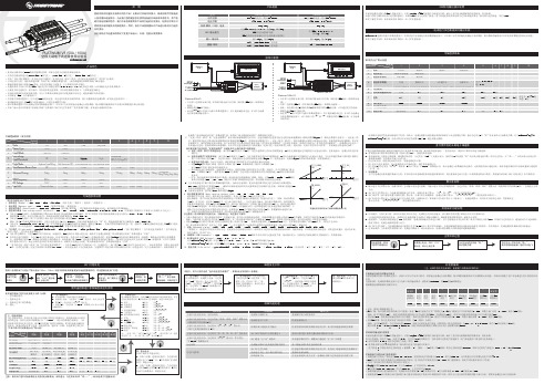
型号 应用范围 电池节数 持续/瞬间(10秒)电流
BEC 输出能力
输入/输出线 重量/体积
产品规格
Platinum-100A-V3 500-550级电直(桨长425-550mm)
2-6S LiPo,5.2V-25.2V 100A/150A
开关BEC,6.0V/7.4V/8.4V,持续10A,瞬间25A, BEC具有直通保护功能
例如使用3节锂电,设定为中截止电压,则该电池组低压保护阈值为:3.15×3=9.45V。 2) 当设定为NiMH电池时,低/中/高情况下截止电压为开机时输入电压的50% / 62.5% / 75%。
例如:使用6节充满电的镍氢电池组,开机上电时电压为1.44×6=8.64V,当低压保护阈值设定为“低”时,则电池组的保护电压阈值为:8.64×50%=4.3V。 3) 当设定为“Customized:2.8V—25.2V”时,可以精确地设定电池组的保护电压阈值(精度达到0.1V)。但此时需使用编程设定盒(注:选购件)或者通过编程设定盒上的USB接口连接
Motor 无刷电机
Platinum-50A-V3: • 白红黑三色排线为油门线(其中细白线为油门信号线,细红线为BEC输出,细黑线为
地线); • 细橙色线为RPM信号输出; • 标注着- + P的三针接口为独立参数设置接口,用于连接编程设定盒,亦可作为电调
运行状态数据输出接口。
RP
15sec
30sec
90sec
7 Advanced Timing
0deg
4deg
8deg
12deg
*15deg
18deg
22deg
26deg
30deg
Customized: 0deg-30deg, Step:1deg
MBR30H30CTG 开关电源整流器 30 V 30 A 用户手册说明书

MBRB30H30CT-1G, NRVBB30H30CT-1G, MBR30H30CTG Switch-mode Power Rectifiers30 V, 30 AFeatures and Benefits•Low Forward V oltage•Low Power Loss/High Efficiency•High Surge Capacity•150°C Operating Junction Temperature•30 A Total (15 A Per Diode Leg)•Guard−Ring for Stress Protection•NRVBB Prefix for Automotive and Other Applications Requiring Unique Site and Control Change Requirements; AEC−Q101 Qualified and PPAP Capable•These Devices are Pb−Free and are RoHS CompliantApplications•Power Supply − Output Rectification•Power Management•InstrumentationMechanical Characteristics:•Case: Epoxy, Molded•EpoxyMeetsUL94V−*********•Weight:1.5 Grams (I2PAK) (Approximately)1.9 Grams (TO−220) (Approximately)•Finish: All External Surfaces Corrosion Resistant and Terminal Leads are Readily Solderable•Lead Temperature for Soldering Purposes:260°C Max. for 10 SecondsSCHOTTKY BARRIERRECTIFIER30 AMPERES, 30 VOLTS13MARKINGDIAGRAMSI2PAK (TO−262)CASE 418DSTYLE 3AYWWB30H30GAKA3TO−220CASE 221ASTYLE 6A= Assembly LocationY= YearWW= Work WeekB30H30= Device CodeG= Pb−Free PackageAKA= Diode PolaritySee detailed ordering and shipping information on page 5 of this data sheet.ORDERING AND MARKING INFORMATIONMAXIMUM RATINGS (Per Diode Leg)Rating Symbol Value UnitPeak Repetitive Reverse Voltage Working Peak Reverse Voltage DC Blocking Voltage V RRMV RWMV R30VAverage Rectified Forward Current (Rated V R) T C = 138°C I F(AV)15APeak Repetitive Forward Current (Rated V R, Square Wave, 20 kHz)I FRM30ANonrepetitive Peak Surge Current(Surge applied at rated load conditions halfwave, single phase, 60 Hz)I FSM260AOperating Junction Temperature (Note 1)T J−55 to +150°C Storage Temperature T stg*55 to +150°C Voltage Rate of Change (Rated V R)dv/dt10,000V/m s Controlled Avalanche Energy (see test conditions in Figures 9 and 10)W AVAL250mJ ESD Ratings:Machine Model = C Human Body Model = 3B> 400> 8000VStresses exceeding those listed in the Maximum Ratings table may damage the device. If any of these limits are exceeded, device functionality should not be assumed, damage may occur and reliability may be affected.1.The heat generated must be less than the thermal conductivity from Junction−to−Ambient: dP D/dT J < 1/R q JA.THERMAL CHARACTERISTICSRating Symbol Value Unit Maximum Thermal ResistanceJunction−to−Case Junction−to−Ambient R q JCR q JA2.070°C/WELECTRICAL CHARACTERISTICS (Per Diode Leg)Rating Symbol Value UnitMaximum Instantaneous Forward Voltage (Note 2) (I F = 15 A, T C = 25°C)(I F = 15 A, T C = 125°C)(I F = 30 A, T C = 25°C)(I F = 30 A, T C = 125°C)v F0.480.400.550.53VMaximum Instantaneous Reverse Current (Note 2) (Rated DC Voltage, T C = 25°C)(Rated DC Voltage, T C = 125°C)i R0.8130mAProduct parametric performance is indicated in the Electrical Characteristics for the listed test conditions, unless otherwise noted. Product performance may not be indicated by the Electrical Characteristics if operated under different conditions.2.Pulse Test: Pulse Width = 300 m s, Duty Cycle ≤ 2.0%.I F , I N S T A N T A N E O U S F O R W A R D C U R R E N T (A M P S )Figure 1. Typical Forward Voltage Figure 2. Maximum Forward VoltageV F , INSTANTANEOUS FORWARD VOLTAGE (VOLTS)10010.10.40.21.00.80.6I R , R E V E R S E C U R R E N T (A M P S )Figure 3. Typical Reverse Current Figure 4. Maximum Reverse Current50V R , REVERSE VOLTAGE (VOLTS)10I F , A V E R A G E F O R W A R D C U R R E N T (A M P S )Figure 5. Current DeratingT C , CASE TEMPERATURE (°C)1201101050140150130160P F O , A V E R A G E P O W E R D I S S I P A T I O N (W A T T S )15I O , AVERAGE FORWARD CURRENT (AMPS)1620510Figure 6. Forward Power Dissipation100.1101520301004681214301525202025250.30.50.70.9I F , I N S T A N T A N E O U S F O R W A R D C U R R E N T (A M P S )V F , INSTANTANEOUS FORWARD VOLTAGE (VOLTS)10010.10.40.21.00.80.60.1100.30.50.70.9I R )50V R , REVERSE VOLTAGE (VOLTS)1015203025C , C A P A C I T A N C E (p F )0V R , REVERSE VOLTAGE (VOLTS)1500025Figure 7. Typical Capacitance2010153000302000250010005005R (t ), T R A N S I E N T T H E R M A L R E S I S T A N C EFigure 8. Thermal Response Junction−to−Caset 1, TIME (sec)BV DUTI L I DV DDt0t1t2t Figure 9. Test Circuit Figure 10. Current−Voltage WaveformsThe unclamped inductive switching circuit shown in Figure 9 was used to demonstrate the controlled avalanche capability of this device. A mercury switch was used instead of an electronic switch to simulate a noisy environment when the switch was being opened.When S1 is closed at t0 the current in the inductor I L ramps up linearly; and energy is stored in the coil. At t1 the switch is opened and the voltage across the diode under test begins to rise rapidly, due to di/dt effects, when this induced voltage reaches the breakdown voltage of the diode, it is clamped at BV DUT and the diode begins to conduct the full load current which now starts to decay linearly through the diode, and goes to zero at t2.By solving the loop equation at the point in time when S1 is opened; and calculating the energy that is transferred to the diode it can be shown that the total energy transferred is equal to the energy stored in the inductor plus a finite amount of energy from the V DD power supply while the diode is in breakdown (from t1 to t2) minus any losses due to finite component resistances. Assuming the component resistive elements are small Equation (1) approximates the total energy transferred to the diode. It can be seen from this equation that if the V DD voltage is low compared to the breakdown voltage of the device, the amount of energy contributed by the supply during breakdown is small and the total energy can be assumed to be nearly equal to the energy stored in the coil during the time when S1 was closed, Equation (2).W AVAL[12LI2LPKǒBV DUTBV DUT–V DDǓW AVAL[12LI2LPKEQUATION (1):EQUATION (2):ORDERING INFORMATIONDevice Package Shipping MBRB30H30CT−1G TO−262(Pb−Free)50 Units / RailNRVBB30H30CT−1G TO−262(Pb−Free)50 Units / RailMBR30H30CTG TO−220(Pb−Free)50 Units / RailTO −220CASE 221A ISSUE AKDATE 13 JAN 2022STYLE 1:PIN 1.BASE2.COLLECTOR3.EMITTER4.COLLECTORSTYLE 2:PIN 1.BASE 2.EMITTER 3.COLLECTOR 4.EMITTERSTYLE 3:PIN 1.CATHODE 2.ANODE 3.GATE 4.ANODESTYLE 4:PIN 1.MAIN TERMINAL 12.MAIN TERMINAL 23.GATE4.MAIN TERMINAL 2STYLE 7:PIN 1.CATHODE 2.ANODE 3.CATHODE 4.ANODE STYLE 10:PIN 1.GATE 2.SOURCE 3.DRAIN 4.SOURCE STYLE 5:PIN 1.GATE 2.DRAIN 3.SOURCE 4.DRAIN STYLE 8:PIN 1.CATHODE 2.ANODE3.EXTERNAL TRIP/DELAY4.ANODESTYLE 6:PIN 1.ANODE 2.CATHODE 3.ANODE 4.CATHODE STYLE 9:PIN 1.GATE2.COLLECTOR3.EMITTER4.COLLECTOR STYLE 11:PIN 1.DRAIN 2.SOURCE 3.GATE 4.SOURCE STYLE 12:PIN 1.MAIN TERMINAL 12.MAIN TERMINAL 23.GATE4.NOT CONNECTEDI 2PAK (TO −262)CASE 418D −01ISSUE DDATE 16 OCT 2007NOTES:1.DIMENSIONING AND TOLERANCING PER ANSI Y14.5M, 1982.2.CONTROLLING DIMENSION: INCH.STYLE 1:PIN 1.BASE2.COLLECTOR3.EMITTER4.COLLECTORSTYLE 2:PIN 1.GATE 2.DRAIN 3.SOURCE 4.DRAINSTYLE 3:PIN 1.ANODE 2.CATHODE 3.ANODE 4.CATHODESTYLE 4:PIN 1.GATE2.COLLECTOR3.EMITTER4.COLLECTORD DIM MIN MAX MIN MAX MILLIMETERSINCHES A 0.3350.3808.519.65B 0.3800.4069.6510.31C 0.1600.185 4.06 4.70D 0.0260.0350.660.89E 0.0450.055 1.14 1.40G 0.100 BSC 2.54 BSC H 0.0940.110 2.39 2.79J 0.0130.0250.330.64S 0.390 REF 9.90 REF V 0.0450.070 1.14 1.78W0.5220.55113.2514.00MBM 0.13 (0.005)T F 0.122 REF 3.10 REF K 0.5000.56212.7014.27ON Semiconductor and are trademarks of Semiconductor Components Industries, LLC dba ON Semiconductor or its subsidiaries in the United States and/or other countries.ON Semiconductor reserves the right to make changes without further notice to any products herein. ON Semiconductor makes no warranty, representation or guarantee regarding the suitability of its products for any particular purpose, nor does ON Semiconductor assume any liability arising out of the application or use of any product or circuit, and specifically disclaims any and all liability, including without limitation special, consequential or incidental damages. ON Semiconductor does not convey any license under its patent rights nor thePUBLICATION ORDERING INFORMATIONTECHNICAL SUPPORTNorth American Technical Support:Voice Mail: 1 800−282−9855 Toll Free USA/Canada Phone: 011 421 33 790 2910LITERATURE FULFILLMENT :Email Requests to:*******************onsemi Website: Europe, Middle East and Africa Technical Support:Phone: 00421 33 790 2910For additional information, please contact your local Sales Representative。
旺盈家居用发esserhair 发结液干压机用户手册,型号:HP4935 00说明书

Register your product and get support at /welcome HairdryerHP4935/00EN User manualCongratulations on your purchase, and welcome to Philips! T o fully benefit from the support that Philips offers, register your product at /welcome.1 Important Read this user manual carefully before you use the appliance and keep it for future reference.WARNING: Do not use this appliance near water. • When the appliance is used in a bathroom, unplug it after use since • the proximity of water presents a risk, even when the appliance is switched off.WARNING: Do not use this appliance near bathtubs, • showers, basins or other vessels containing water.Do not insert metal objects into the air grilles to avoid • electric shock.Never block the air grilles.• Before you connect the appliance, ensure that the voltage indicated • on the appliance corresponds to the local power voltage.Do not use the appliance for any other purpose than described in • this manual.Do not use the appliance on artificial hair.• When the appliance is connected to the power, never leave it • unattended.Always unplug the appliance after use. • Never use any accessories or parts from other manufacturers or that • Philips does not specifically recommend. If you use such accessories or parts, your guarantee becomes invalid.Do not wind the mains cord round the appliance. • If the mains cord is damaged, you must have it replaced by Philips, a • service centre authorised by Philips or similarly qualified persons in order to avoid a hazard.This appliance is not intended for use by persons (including children) • with reduced physical, sensory or mental capabilities, or lack of experience and knowledge, unless they have been given supervision or instruction concerning use of the appliance by a person responsible for their safety.Children should be supervised to ensure that they do not play with • the appliance.For additional protection, we advise you to install a residual current • device (RCD) in the electrical circuit that supplies the bathroom. This RCD must have a rated residual operating current not higher than 30mA. Ask your installer for advice.If the appliance overheats, it switches off automatically. Unplug the • appliance and let it cool down for a few minutes. Before you switch the appliance on again, check the grilles to make sure they are not blocked by fluff, hair, etc.Electromagnetic fields (EMF)This appliance complies with all standards regarding electromagnetic fields (EMF). If handled properly and according to the instructions in this user manual, the appliance is safe to use based on scientific evidence available today.Environmentat the end of its life, but hand it in at an official collection point for recycling. By doing this, you help to preserve the environment.2 Dry your hair1 Connect the plug to a power supply socket.For precise drying, attach the concentrator (• ) onto the hairdryer (). T o disconnect the attachment, pull it off the hairdryer.•2 Adjust the temperature switch () to airflow, Press the cool shot button (3 Adjust the airflow switch () to for gentle airflow for drying short hair and styling, for strong airflow for fast drying, or to switch off.The ion function activates when an airflow is selected, and the ion • indicator () lights up. The function provides additional shine and reduces frizz.When the function is on, a special odor may be smelt. It is normal »and caused by the ions which are generated.After use:1 Switch off the appliance and unplug it.2 Place it on a heat-resistant surface until it cools down.3 Clean the appliance by damp cloth.4 Keep it in a safe and dry place, free of dust. Y ou can also hang it with the hanging loop ().3 Guarantee and service If you need information or if you have a problem, please visit the Philips website at or contact the Philips Customer Care Centre in your country (you find its phone number in the worldwide guarantee leaflet). If there is no Consumer Care Centre in your country, go to your local Philips dealer.© Royal Philips Electronics N.V.2009All rights reserved.Specifications are subject to change without notice. Trademarks are the property of Koninklijke Philips Electronics N.V.or their respective owners.PDCC-20093140 035 20731。
聚和太阳能30A PWM 充电控制器 (带 LCD 显示屏) 用户手册说明书

PWM Charge Controller with LCD Display30AUser ManualProduct Features1. 12V/ 24 V system voltages are automatically recognized.2. Charging program options for sealed, GEL and flooded lead-acid batteries and lithium batteries are available.3. An upgraded 3-stage PWM charging algorithm is adopted. Application of an equalizing charge to the battery periodically or when over discharged, can effectively prevent the battery from non-equalization and sulfuration, thus extending the battery's service life (with the exception of GEL and lithium batteries).4. With temperature compensation employed, charging parameters can be automatically adjusted (with the exception of lithium batteries).5. A wide range of load working modes facilitate the product's application to different types of street lights and monitoring devices.6. The product provides overcharge, over-discharge, overload protection, as well as short-circuit and reverse-connection protection.7. By virtue of an advanced load starting method, large-capacitance loads can be started smoothly.8. A range of parameter settings and power-down saving functions are available, thus requiring no repeated setting.9. The product provides a dot matrix graphic LCD screen and a human-machine interface with 2 keys.10. The user-friendly design of browser and dynamic interfaces ensures convenient and intuitive operations.11. (An optional communication function) provides a RJ12 data port (output of TTL232 level or blue tooth signals), with the data adopting the standard Modbus protocol, can be used together with our upper computer Monitoring software or mobile phone APP.12. Boasting an industrial grade design, the product can function well in various tough conditions.13. TVS lighting protection is adopted.Panel StructureInstallation Instructions and Precautions1.The controller shall be installed securely, and its dimensions are as follows:External dimensions: 164.0×103.5×47.0 (mm)Installation dimensions: 154×85 (mm)2.Installation hole diameter:3.5(mm)Dimensions in mm3.Precautions:① For a 12 V system, the LCD screen displays "12 V" on the lower-left corner. And it’s similar for 24 V and48 V systems.②The first step is to connect the battery. If the connection is made correctly, the controller screen willlight up; otherwise, check whether the connection is correct.③The second step is to connect the solar panel. If sunlight is present and strong enough (the solarpanel voltage is greater than battery voltage), the sun icon on the LCD screen is on; otherwise, check w hether the connection is correct (it’s recommended that the operation be performed under the debugging mode).the current shall not exceed the cont roller’s rated current.⑤As the controller will generate heat during operation, it's recommended that the controller be installed inan environment with good ventilation conditions.⑥Choose cables with large enough capacity for connection, in case too much loss incurred on the linescauses the controller to misjudge.⑦The controller has a common positive pole inside. If grounding is needed, ground the positive pole.⑧It's important to fully charge the battery regularly. At least once full charging every month isrecommended, and failure to do that may cause permanent damage to the battery. Only when in-flow energy outpaces that out-flow energy can the battery be charged fully, Users shall bear this in mind when confituring the system.⑨Check whether the controller's each connection terminal is tightened securely; if not, it may sufferdamage when the current passes.State IndicatorsLCD Icon Indicated Object State MeaningDay recognition Steady on Day timeNightrecognitionSteady on Night timeSolar panel Steady on Solar panel indicationBOOSTCharging state Steady on Boost chargingFLOAT Steady on Floating charging EQUATIZE Steady on Equalizing chargingBattery Quick flashing Battery overvoltageSlowflashingBattery overvoltageBattery SOC 4 dashes100% 3 dashes 75% 2 dashes 50% 1 dash 25% 0dash 0%LoadSteady on Load turned on Steady on Load turned off Quick flashingOverload or short-circuitprotectionFive Load Working Modes1.Pure light control (0): When sunlight disappears and the light intensity drops to the starting point (light control off), the controller initiates a 10-minute delay (settable) to confirm the starting signal, and then switches on the load for operation. When sunlight emerges and the light intensity reaches the starting point, the controller initiates a 1-minute (fixed) delay to confirm the shutting-down signal, and then shuts down the output to stop the load's operation.2. Light control + time control (1 to 14): The starting process is the same as pure light control. After operating for a preset period of time (settable from 1 to 14 hours), the load stops operation automatically.3. Manual Mode (15): In this mode, the user can switch the loa d on or off by the keys, no matter whether it’s day or night.4. Debugging mode (16):When the solar panel voltage is higher than the “light control off” voltage, switch off the load immediately; when the solar panel voltage is lower than the “light control on” voltage, switch on the load immediately.5. Normal on (17): The energized load keeps in output state.LED Display ModeLEDDisplayMode0 Pure li ght control mode9 Light control + time control (9 hours)1 Light control + timecontrol (1 hour)10Light control + timecontrol (10 hours)2 Light control + timecontrol (2 hours)11Light control + timecontrol (11 hours)3 Light control + timecontrol (3 hours)12Light control + timecontrol (12 hours)4 Light control + timecontrol (4 hours)13Light control + timecontrol (13 hours)5 Light control + timecontrol (5 hours)14Light control + timecontrol (14 hours)6 Light control + timecontrol (6 hours)15 Manual mode7 Light control + timecontrol (7 hours)16 Debugging mode (default)8 Light control + timecontrol (8 hours)17 Normal on modeLoad Working Mode SettingsIn the load mode menu, long press for 2s, and the number (e.g. 15) will begin to flash. Press to adjust the mode (from 0 to 17), and then long press again for 2s to complete and save the setting. Note:1. After parameter adjustment, if is not pressed and held long enough for exiting , the system exits to the main menu after 12s, and the parameter that was set is not saved.2. When the system is saving data, the screen may shake slightly. This is normal and the user may ignore it.Safety Advice1) When connected to a 24 V or 48V system, the solar panel terminal voltage may exceed the limit for humansafety. If operation is to be performed, be sure to use insulation tools and keep your hands dry2) If the battery is reversely connected, the controller itself won't be damaged, but the load end will have anegative voltage output, which may damage your load device. Take care not to let this happen.3) In a 48 V system, if the battery or solar panel end is reversely connected, the controller is highly likely toget damaged.4) The battery contains a large amount of energy. Therefore, in no cases should the battery be short circuited.It's recommended that a fuse be serially connected to the battery.5) Keep the battery away from fire sparks, as the battery may produce flammable gas.6) Keep children away from the battery and controller.7) Follow the safety advice provided by the battery manufacturer.LCD Screen IllustrationBrowsing Menu on LCD Screen1).Continuously press,the screen will display the following in order: "main menu"---"solar panel voltage"---" solar panel current"---"battery capacity"---"battery voltage"---"discharging current"---"charging amp-hrs"---" discharging amp-hrs"---" temperature inside controller"---" load mode"---" load mode settings"---"error code", and then back to "main menu". If the keys are not operated for 12s, the system will automatically return to display the "main menu"Setting Menu on LCD Screen2). When "load mode" is displayed, long press to enter into the load mode setting Press to adjust the mode, and long press for 2s to save and exit; or else, the system will not save the setting that was just made and automatically exits the setting interface after 12s.Battery Types, Charging Voltages (Lithium Battery), Over-Discharge Return and Over-Discharge Voltage SettingsIn the non-load mode menu:1) When is long pressed, the first interface entered is for battery type setting, and the flashing one is the battery type currently selected. Press to selet among FLD/GEL/SLD/LI.2) After selection, short press to enter into over-discharge return and over-discharge voltage settings; or the first to enter charging voltage setting menu for lithium battery.3) After parameters have been set, long press for 2s to save and exit.Parameters shall be set according to the following rule: over-discharge voltage < over-discharge return voltage <= under-voltage warning < float charging voltage < boost charging return <= equalizing charging voltage <overcharge voltage; and two adjacent values shall have a difference greater than 0.5V.Charging and Discharging Overload Pretection and Recovery TimeIn the charging and discharging overload protection mechanism, the relation between overload current and protection time is as follows: An overload current 1.25 times of the rated current initiates a delay of 30s before starting protection; similarly, 1.5 times, 5s and 2 times, 1s.Overload recovery: automatic recovery after 1 minute.Load Short Circuit and RecoveryShort-circuit automatic recovery time: 1st time, 5 s; 2nd time, 10 s; 3rd time, 15 s; 4th time, 20 s; 5th time, 4 hours or automatic recovery the next day; or long press to make the load resume output. Communication Port Line Sequence (Only for Controllers with Communication Functions)Controller communication port RJ12 (6-pin)Error Code ListCode on LCD screen Corresponding errorE0 No errorE1 Battery over-dischargingE2 Battery overvoltageE3 Under voltage warningE4 Load short circuitE5 Load overcurrentE6 Controller inner temperature over heatE8 Charging current too highE10 Solar panel input voltage too highCommon Problems and SolutionsSymptoms Causes and SolutionsLCD screen does not light up.Check whether the battery is correctly connected.Incomplete display or no renewal on LCD screen Check whether the ambient temperature is too low and whether the display recovers when the temperature rises.No charging with sunlight present Check whether the solar panel is correctly connected, and contact is good and reliable.Check whether the solar panel voltage falls below the battery voltage.The sun icon does not light up, while the solar panel icon does. The battery voltage is normal, but there is no output. The load will be switched on automatically after 10 minutes (set by the user).The battery icon flashes quickly, and there is no output. System overvoltage. Check whether the battery voltage is too high.The battery icon flashes slowly, and there is no output. The battery is over-discharged, and will recover after recharged adequately.The load icon flashes quickly, and there is no output. The load's power exceeds the rated value or the load is short-circuited. After the problem is solved, long press the key or wait until it recovers automatically.Other symptoms Check whether wiring is sound and reliable, and system voltage is correctly recognized.Technical Data SheetRated current30ASystem voltage Automatic recognition of 12V/24VMax. Solar energy input voltage <55V Max. voltage at thebattery end <34VBattery type ParametersFlooded FLDSealed SLDGEL GELLithium LIDefault SLDOvervoltage protection 16.0V×1/12V ; ×2/24V ; ×4/48V ;Equalizing charging voltage 14.8 14.6 - - Boost chargingvoltage14.6 14.4 14.2 14.4 Floating chargingvoltage13.813.813.8-Charging recoveryvoltage 13.2VOver-discharge recovery voltage 12.5V (settable with the keys ) Over-dischargevoltage 11.0V (settable with the keys ) Equalizing charging interval 30days - -Equalizing charging time 1H-- Boost chargingtime 2H - Temperature compensation -3.0mV/℃/2V-Light control voltage Light control on 5V, light control off 6 V (light control on plus 1V)×1/12V ; ×2/24V ; ×4/48V ; Light control judgment time 10 minutes USB function YesNoNoOperating temperature -25℃to+55℃;IP protection degree IP30 Net weight 390gProtection functions Battery reverse connection protection, solar panel reverse connection protection, reverse charging protection at nightCharging overload protection, overcurrent protection , short circuit protectionDimensions164.0×103.5×47.0(mm)The content of this manual is subjectto change without prior notice.。
SFA Companies HW93642 和 HW93652 汽车扬升机操作指南和零件手册说明书

Operating Instructions & Parts ManualSFA Companies10939 N. Pomona Ave. Kansas City, MO 64153******************************************Model Number HW93642 HW93652Service JacksCapacity 2 Ton 3 TonThis is the safety alert symbol. It is used to alert you to potential personal injury hazards. Obey all safety messages that follow this symbol to avoid possible injury or death.Assembled in the US with US and GlobalComponentsSAFETY AND GENERAL INFORMATIONSave these instructions. For your safety read, understand, and follow the information provided with and on this jack. The owner and operator of this equipment shall have an understanding of this jack and safe operating procedures before attempting to use. The owner and operator shall be aware that use and repair of this product may require special skills and knowledge. Instructions and safety information shall be conveyed in the operator's native language before use of this jack is authorized. If any doubt exists as to the safe and proper use of this jack, remove from service immediately. Inspect before each use. Do not use if broken, bent, cracked, or damaged parts (including labels) are noted. Any jack that appears damaged in any way, operates abnormally or is missing parts, shall be removed from service immediately and the manufacturer notified. If you suspect that the jack was subjected to a shock load (a load dropped suddenly, unexpectedly upon it), immediately discontinue use until the jack has been checked by a factory authorized service center (contact distributor or manufacturer for list of Authorized Service Centers). It is recommended that an annual inspection be done by qualified personnel. Replace worn or damaged parts with Hein-Werner Authorized Replacement Parts only. Labels and owner’s manuals are available from manufacturer.PRODUCT DESCRIPTIONHein-Werner Hydraulic Service Jacks are designed to lift, not support, rated capacity loads consisting of one end of a vehicle. Immediately after lifting, the load must be supported by a pair of appropriately rated jack stands.WARNING: Never use this jack as a stand alone device. After lifting, immediately support the lifted vehicle with a pair of appropriately rated vehicle stands.Figure 1 - Typical Service Jack ComponentsHandle ForkPREPARATION (ref. Figure 1)Before Use1. Verify that the product and application are compatible, if in doubt contact Hein-Werner technical service.2. Before use, read the operator's manual completely and familiarize yourself thoroughly with the product, its components and recognize the potential hazards associated with its use.3. Insert handle into handle fork. Tighten bolt on handle fork to prevent accidental removal of handle while in use.WARNING: Do not lift or carry jack by handle. Handle could dislodge and jack fall, resulting in possible injuryor property damage.4. To familiarize yourself with the basic operation of the jack, locate and turn the release valve (handle):a. Clockwise until firm resistance is felt to further turning. This is the ‘CLOSED’ release valve position used when raising the load.b. Counter-clockwise , but no more than 1/2 full turn from the closed position. This is the ‘OPEN’ release valve position used to lower the load.5. With saddle fully lowered, and release valve closed, pump the operating handle. If lift arm responds immediately, jack is ready for use. If jack does not respond, followBleeding/Venting Trapped Air procedure below.6. Jack should roll freely. Raise and lower the unloaded saddle throughout the lift range before putting into service to ensure the pump and release valve operate smoothly.7. Replace worn or damaged parts and assemblies with Hein-Werner Replacement Parts only. Lubricate as instructed in Maintenance Section.Bleeding/Venting Trapped AirWith the Release Valve in the OPEN position (4b above) and Saddle fully lowered, locate and remove the Oil Filler Screw. Pump Handle 6 to 8 full strokes. This will help release any pressurized air which may be trapped within the reservoir. Check oil level and reinstall Oil Filler Screw.OPERATIONLiftingWARNING: Lift only on areas of the vehicle as specified by the vehicle manufacturer.1. Follow the vehicle manufacturer’s recommended guidelines for lifting. Engage the emergency brake and chock each unlifted wheel in both directions to prevent inadvertent vehicle movement.2. Locate and close the release valve by turning the handle clockwise until firm resistance is felt.3. Refer to the vehicle manufacturer owner’s manual to locate approved lifting points on the vehicle. Center jacksaddle under lift point.4. Verify lift point then use handle pump to contact lift point. To lift, pump handle until load reaches desired height.5. Transfer the load to appropriately rated jack stands.WARNING: Never work on, under or around a load supported only by a hydraulic jack.WARNING: Overloading may cause hydraulic system failure and sudden loss of load.LoweringWARNING: Clear all tools and personnel before lowering vehicle. The further release valve (handle) is turnedcounter-clockwise, the faster the load will descend. Maintain control of the speed at which the load lowers at all times.1. Raise load high enough to clear the jack stands.2. Remove jack stands, carefully.3. Slowly turn the release valve (handle) counter-clockwise, but no more than 1/2 full turn. If the load fails to lower : a. Use another jack to raise the vehicle high enough to reinstall jack stands.b. Remove the malfunctioning jack and then repeat steps 1 and 2 to remove the jack stands.c. Using the functioning jack, lower the vehicle.4. After removing jack from under the load, push saddle down to reduce ram exposure to rust and contamination.MAINTENANCENOTICE:Use only quality grade hydraulic jack oil. Avoid mixing different types of fluid and NEVER use brake fluid, turbine oil, transmission fluid, motor oil or glycerin. Improper fluid can cause failure of the jack and the potential for sudden and immediate loss of load. Hein-Werner hydraulic jack oil HW93291 or equivalent is recommended.Adding oil1. Lower saddle fully.2. Set jack in its upright, level position.3. Locate and remove air vent screw.4. Fill with hydraulic fluid until slightly above the inner cylinder as seen from the air vent screw hole.5. Reinstall the air vent screw.Changing oilFor best performance and longest life, completely replace hydraulic fluid at least once a year.1. Lower saddle fully.2. Remove the air vent screw.3. Lay the jack on its side and drain the fluid into a suitable container.NOTICE: Dispose of hydraulic fluid in accordance with local environmental regulations.4. Fill with hydraulic fluid until slightly above the inner cylinder as seen from the air vent screw hole.5. Reinstall the air vent screw.LubricationA periodic coating of light lubricating oil to pivot points, axles and hinges will help to prevent rust and assure that wheels, casters and pump assemblies move freely.CleaningPeriodically check pump piston and ram for signs of rust or corrosion. Clean as needed and wipe with an oily cloth.NOTICE: Never use sandpaper or abrasive material on these surfaces.StorageLower the saddle to its lowest position when not in use.REPLACEMENT PARTS(ref. pages 6 & 7)Not all components of the jack are replacement items, but are illustrated as a convenient reference of location and position in the assembly sequence. When ordering parts, give model number, part number and parts description.Call or write for current pricing: Hein-Werner Customer Support, 10939 N. Pomona Ave. Kansas City, MO 64153.Replacement Parts Illustration for Model HW93642 & HW93652 (refer to parts list on page 7) Frame SectionFigure 2 - Parts Illustration for Model HW93642 & HW93652Replacement Parts List for Model HW93642 & HW93652 (refer to parts drawing on page 6)TWO YEAR LIMITED WARRANTYFor a period of two (2) years from date of purchase, SFA Companies will repair or replace, at its option, without charge, any of its products which fails due to a defect in material or workmanship under normal usage. This limited warranty is a consumer's exclusive remedy.Performance of any obligation under this warranty may be obtained by returning the warranted product, freight prepaid, to SFA Companies Warranty Service Department, 10939 N. Pomona Ave., Kansas City, MO 64153.Except where such limitations and exclusions are specifically prohibited by applicable law:(1) THE CONSUMER'S SOLE AND EXCLUSIVE REMEDY SHALL BE THE REPAIR OR REPLACEMENT OF DEFECTIVEPRODUCTS AS DESCRIBED ABOVE(2)SFA COMPANIES SHALL NOT BE LIABLE FOR ANY CONSEQUENTIAL OR INCIDENTAL DAMAGE OR LOSSWHATSOEVER.(3) ANY IMPLIED WARRANTIES, INCLUDING WITHOUT LIMITATION THE IMPLIED WARRANTIES OFMERCHANTABILITY AND FITNESS FOR A PARTICULAR PURPOSE, SHALL BE LIMITED TO TWO YEARS, OTHERWISE THE REPAIR, REPLACEMENT OR REFUND AS PROVIDED UNDER THIS EXPRESS LIMITED WARRANTY IS THE EXCLUSIVE REMEDY OF THE CONSUMER, AND IS PROVIDED IN LIEU OF ALL OTHER WARRANTIES, EXPRESS OR IMPLIED.(4) ANY MODIFICATION, ALTERATION, ABUSE, UNAUTHORIZED SERVICE OR ORNAMENTAL DESIGN VOIDSTHIS WARRANTY AND IS NOT COVERED BY THIS WARRANTY.Some states do not allow limitations on how long an implied warranty lasts, so the above limitation may not apply to you. Some states do not allow the exclusion or limitation of incidental or consequential damages, so the above limitation or exclusion may not apply to you. This warranty gives you specific legal rights, and you may also have other rights which vary from state to state.SFA Companies10939 N. Pomona Ave. Kansas City, MO 64153816-891-6390******************************************。
- 1、下载文档前请自行甄别文档内容的完整性,平台不提供额外的编辑、内容补充、找答案等附加服务。
- 2、"仅部分预览"的文档,不可在线预览部分如存在完整性等问题,可反馈申请退款(可完整预览的文档不适用该条件!)。
- 3、如文档侵犯您的权益,请联系客服反馈,我们会尽快为您处理(人工客服工作时间:9:00-18:30)。
HW25A说明书
兼容好盈科技无刷电调编程设定卡
输出能力:持续电流25A,短时电流30A(不少于10秒);
电源输入:2-3节锂电池组或5—12节镍氢/镍镉电池组;
BEC输出:2A (线性稳压模式-linear mode);
最高转速:2极马达210000转/分钟,6极马达70000转/分钟,12极马达35000转/分钟;
尺寸: 45mm(长)*24mm(宽)*11mm(高);
重量: 22g(含散热片);
产品功能
1.安全上电功能:接通电源时,无论油门摇杆处于任何位置均不会立即启动电机,避免造成人身伤害;
2.油门行程校调功能:适应不同遥控器油门行程的差别,提高油门响应的线性度,具备平滑、细腻的调速手感和一流的调速线性;
3.程序设定项目:
●刹车设定:无刹车/有刹车,出厂默认值为无刹车。
●电池类型:Li-xx(锂电池)/ Ni-xx(镍镉或镍氢),默认值为 Li-xx(锂电池)。
●低压保护模式:降低功率/关闭输出,默认值为降低功率。
●低压保护阈值:低/中/高,默认值为中截止电压。
◆ 当设定使用的是Li-xx 电池,则自动判断锂电颗数,低/中/高情况下每颗电池的截止电压分别为:2.6V、2.85V、3.1V。
◆当设定使用的是Ni-xx 电池,电调上电时自动侦测电池组的电压,低/中/高情况截止电压为开机时输入电压的0%、45%、60% (0% 意味着不做低压保护)
●启动模式:普通/柔和/超柔和启动,默认值为普通启动。
◆普通启动适用于固定翼,可以在0.2秒内迅速启动马达
◆柔和启动/超柔和启动适用于直升机;柔和启动和超柔和启动的初始转速都比较低,从启动到全速分别需要1秒和2秒钟,但启动后若关闭油门,3秒内再次启动时则均以普通模式启动,以免在做一些特技动作飞行时因反应过慢而导致摔机。
●进角:低/中/高,默认值为中进角。
一般情况下,低进角可以适应更多的马达,但为提高效率,建议2极马达使用低进角,6极以上马达使用中进角。
为提高转速,可以将进角设为高进角。
在更改进角设置后,应先在地面进行测试然后再飞行。
●恢复出厂默认值
4.全面的保护功能:
●欠压保护:由用户通过程序设定;
●过压保护:输入电压超过18伏不予启动,自动保护,同时发出急促的“哔哔”告警音;
●过热保护:内置温度检测电路,MOS管温度过高时电调自动关断;
●遥控信号丢失保护:遥控信号丢失1秒后降低功率,再有2秒无遥控信号则关闭输出;
油门设置办法:
1.将油门微调调最小
2.油门摇杆推最大(顶上)
3.电调接CH3上.通电.听到DIDI声音后(大约通电后3-5秒)..
4.遥控油门拉最小..再次听到DIDI..和一声DI...长响....
HW30A说明书
兼容好盈科技无刷电调编程设定卡
输出能力:持续电流30A,短时电流35A(不少于10秒);
电源输入:2-3节锂电池组或5—12节镍氢/镍镉电池组;
BEC输出:2A (线性稳压模式-linear mode);
最高转速:2极马达210000转/分钟,6极马达70000转/分钟,12极马达35000转/分钟;
尺寸: 45mm(长)*24mm(宽)*11mm(高);
重量: 25g(含散热片);
产品功能
1.安全上电功能:接通电源时,无论油门摇杆处于任何位置均不会立即启动电机,避免造成人身伤害;
2.油门行程校调功能:适应不同遥控器油门行程的差别,提高油门响应的线性度,具备平滑、细腻的调速手感和一流的调速线性;
3.程序设定项目:
●刹车设定:无刹车/有刹车,出厂默认值为无刹车。
●电池类型:Li-xx(锂电池)/ Ni-xx(镍镉或镍氢),默认值为 Li-xx(锂电池)。
●低压保护模式:降低功率/关闭输出,默认值为降低功率。
●低压保护阈值:低/中/高,默认值为中截止电压。
◆ 当设定使用的是Li-xx 电池,则自动判断锂电颗数,低/中/高情况下每颗电池的截止电压分别为:2.6V、2.85V、3.1V。
◆当设定使用的是Ni-xx 电池,电调上电时自动侦测电池组的电压,低/中/高情况截止电压为开机时输入电压的0%、45%、60% (0% 意味着不做低压保护)
●启动模式:普通/柔和/超柔和启动,默认值为普通启动。
◆普通启动适用于固定翼,可以在0.2秒内迅速启动马达
◆柔和启动/超柔和启动适用于直升机;柔和启动和超柔和启动的初始转速都比较低,从启动到全速分别需要1秒和2秒钟,但启动后若关闭油门,3秒内再次启动时则均以普通模式启动,以免在做一些特技动作飞行时因反应过慢而导致摔机。
●进角:低/中/高,默认值为中进角。
一般情况下,低进角可以适应更多的马达,但为提高效率,建议2极马达使用低进角,6极以上马达使用中进角。
为提高转速,可以将进角设为高进角。
在更改进角设置后,应先在地面进行测试然后再飞行。
●恢复出厂默认值
4.全面的保护功能:
●欠压保护:由用户通过程序设定;
●过压保护:输入电压超过18伏不予启动,自动保护,同时发出急促的“哔哔”告警音;
●过热保护:内置温度检测电路,MOS管温度过高时电调自动关断;
●遥控信号丢失保护:遥控信号丢失1秒后降低功率,再有2秒无遥控信号则关闭输出;
油门设置办法:
1.将油门微调调最小
2.油门摇杆推最大(顶上)
3.电调接CH3上.通电.听到DIDI声音后(大约通电后3-5秒)..
4.遥控油门拉最小..再次听到DIDI..和一声DI...长响....。