Wiz企业版 使用指南
WIZ200WEB 用户手册说明书
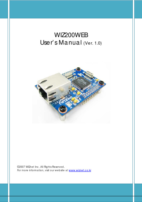
Document History InformationRevision Data DescriptionVer. 1.0 2008. 12. Release with WIZ200WEB launching23WIZnet’s Online Technical SupportIf you have any questions or want more information about WIZnet products, submit your question to the Q&A Board on the WIZnet website.(www.wiznet.co.kr) A WIZnet engineer will have an answer for you as soon as possible.4Table of Contents1. Introduction ......................................................................................................................................... 7 1.1. Main Function .........................................................................................................................................................7 1.2. Specification ............................................................................................................................................................8 1.3.Contents (WIZ200WEB-EVB) (8)2. Block Diagram ..................................................................................................................................... 93. WIZ200WEB Base Board .................................................................................................................. 114. Getting Started .................................................................................................................................. 16 4.1.Configuration Tool (16)4.1.1. Basic Configuration .................................................................................................................................. 16 4.1.2. Firmware Upload ....................................................................................................................................... 17 4.1.3. Webpage Upload ...................................................................................................................................... 19 4.1.4. Use of Rom File Maker rev3.0 .. (20)4.2.Operation Test (22)4.2.1. Hardware Interface ................................................................................................................................... 22 4.2.2.Testing the Function of Web Server (23)5. Programmer’s Guide ........................................................................................................................ 26 5.1. Memory Map ....................................................................................................................................................... 26 5.2. WIZ200WEB Firmware ................................................................................................................................... 26 5.3. Compile .................................................................................................................................................................. 28 5.4.Downloading (28)6. WIZ200WEB Hardware Specification ............................................................................................ 31 6.1. Parameters ............................................................................................................................................................ 31 6.2. Specification ......................................................................................................................................................... 31 6.3.Board Dimensions and Pin Assignment (31)6.3.1. Pin Assignment .......................................................................................................................................... 31 6.3.2. Size .................................................................................................................................................................. 32 6.3.3.Connector Specification (33)7. Warranty (35)5TablesTable 1. WIZ200WEB Specification .................................................................................................................8 Table 2. Contents of WIZ200WEB ...................................................................................................................9 Table 3. WIZ200WEB PIN MAP ..................................................................................................................... 12 Table 4. Expansion Connector ....................................................................................................................... 15 Table 5. WIZ200WEB Testing Environment .............................................................................................. 22 Table 6. WIZ200WEB Main Source .............................................................................................................. 27 Table 7. WIZ200WEB PINMAP .. (31)6FiguresFigure 1. Block Diagram .................................................................................................................................. 10 Figure 2. WIZ200WEB Base Board Layout ............................................................................................... 11 Figure 3. AVR JTAG Connector...................................................................................................................... 12 Figure 4. AVR ISP Connector ......................................................................................................................... 12 Figure 5. WIZ200WEB PIN MAP ................................................................................................................... 12 Figure 6. WIZ200WEB LED .............................................................................................................................. 13 Figure 7. WIZ200WEB Switch ........................................................................................................................ 13 Figure 8. WIZ200WEB 16x2 LCD .................................................................................................................. 14 Figure 9. WIZ200WEB VR ................................................................................................................................ 14 Figure 10. WIZ200WEB T emperature Sensor .......................................................................................... 15 Figure 11. Configuration T ool ....................................................................................................................... 16 Figure 12. Board Search Window ................................................................................................................ 18 Figure 13. Open dialog box for uploading ............................................................................................. 19 Figure 14. Firmware uploading window ................................................................................................... 19 Figure 15. Complete Uploading ................................................................................................................... 19 Figure 16. Flash Rom Image File .................................................................................................................. 20 Figure 17. ROM File Maker ............................................................................................................................ 21 Figure 18. ROM Image File Make ................................................................................................................ 21 Figure 19. WIZ200WEB External Interface ................................................................................................ 22 Figure 20. WIZ200WEB index page ............................................................................................................ 23 Figure 21. WIZ200WEB Digital Output Page .......................................................................................... 24 Figure 22. WIZ200WEB Digital Input Page .............................................................................................. 24 Figure 23. WIZ200WEB Analog Input Page ............................................................................................. 25 Figure 24. WIZ200WEB Memory Map ....................................................................................................... 26 Figure 25. AVR Studio ...................................................................................................................................... 28 Figure 26. ATmega128 ISP .............................................................................................................................. 29 Figure 27. WIZ200WEB Boot Loader Program ....................................................................................... 30 Figure 28. WIZ200WEB Pin Map .................................................................................................................. 31 Figure 29. WIZ200WEB Module Dimension ............................................................................................ 32 Figure 30. WIZ200WEB Base Board Size................................................................................................... 33 Figure 31. RJ-45 PIN Assignment ................................................................................................................ 33 Figure 32. RJ-45 PIN Assignment ................................................................................................................ 34 Figure 34. RS-232 PIN Assignment . (34)71. IntroductionWIZ200WEB provides the tiny embedded web server operating on low-speed MCU. It controls digital output or monitors digital and analogue input through web browser. The webpage is stored in the serial flash memory of the board, and can be updated through network.1.1. Main FunctionOperates as HTTP ServerGuarantee system stability and reliability by using W5300, the hardwired chip Provides Configuration Tool Program for easy control and confiuration Supports 10/100 Mbps Ethernet RoHS Compliant81.2. SpecificationITEMDescriptionMCUATmega128(having internal 128K Flash, 4K SRAM, 4K EEPROM, external 32K SRAM, 512K Serial Flash)ProtocolsTCP/IP - W5300 (Ethernet MAC & PHY Embedded)UDP – Configuration HTTP Server DHCPNetwork Interface 10/100 Mbps Auto-sensing, RJ-45 Connector Input Voltage DC 5V Power ConsumptionUnder 180mATemperature 0°C ~ 80°C (Operation), -40°C ~ 85°C (Storage) Humidity10 ~ 90%Table 1. WIZ200WEB Specification1.3. Contents (WIZ200WEB-EVB)WIZ200WEB ModuleWIZ200WEB Base Board9CD (Configuration Tool Program, Firmware, Manual areincluded)LAN Cable5V Power AdaptorTable 2. Contents of WIZ200WEB☞ If any missing item is found, contact to the shop you purchased.2. Block Diagram10Figure 1. Block DiagramThe main MCU of WIZ200WEB is 8 bit AVR (ATmega128). The Ethernet is processed by W5300, the hardwired TCP/IP chip. When connected to the IP address of the board at the web browser, the webpage in the serial flash memory is transmitted and displayed. Each webpage enables controlof digital input & output, analogue input and network configuration on the web.3. WIZ200WEB Base BoardWIZ200WEB module can be tested by using base board.11Figure 2. WIZ200WEB Base Board Layout①PowerThe power can be controlled by using power switch after connecting the DC 5V (500mA)adaptor.②ATmega128 JTAG ConnectorFigure 3. AVR JTAG Connector12③ATmega128 ISP ConnectorFigure 4. AVR ISP Connector④WIZ200WEB Module ConnectorThe connector has below pin map.Figure 5. WIZ200WEB PIN MAPJ3 J23.3V 3.3V ADC0/PF0 ADC1/PF1GND GND ADC2/PF2 ADC3/PF3SCL/INT0/PD0 SDA/INT0/PD1 ADC4/PF4 ADC5/PF5RXD1/INT2/PD2 TXD1/INT3/PD3ADC6/PF6 ADC7/PF7ICP1/PD4 XCK1/PD5 AREF PB4T1/PD6 T2/PD7 PB5 PB6SS/PB0 SCK/PB1 PB7 PE7MOSI/PB2 MISO/PB3 PE5 PE6RXD0/PE0 TXD0/PE1 PE3 PE4GND GND /RESET PE2Table 3. WIZ200WEB PIN MAP13⑤ Serial Connector(UART0)The debugging information is transmitted through Serial connector when proceeding development.⑥ Serial Connector(UART1)The debugging information is transmitted through Serial connector when proceeding development. ⑦ LED4 LEDs are installed in the WebServer Base Board, and connected to PORTB.4~7. .Figure 6. WIZ200WEB Base Board LED⑧ System Reset Switch⑨ SwitchSwitch is connected to PORTE.5~6. It is the slide switch.Figure 7. WIZ200WEB Base Board Switch⑩ 16X2 character LCD16x2 LCD is controlled with the method of 4 bit control It is connected to PORTD andPORTE.14Figure 8. WIZ200WEB Base Board 16x2 LCD⑪Variable ResistorIn order to test the analog data easily, you can use variable resistor and get the input valueof analog variable. Variable resistor is connected to ADC0 channel.Figure 9. WIZ200WEB Base Board VR⑫Digital Temperature SensorMicrochip’s TC77 having 12bit resolutions is used for temperature sensor. Temperaturesensor can be controlled by SPI and selected through PB0.Figure 10. WIZ200WEB Base Board Temperature Sensor15⑬Extension ConnectorIt is the connector (J12) to extend to GPIO and the function pins of ATmega128NO FUNCTION NO FUNCTION1 NC2 5V3 NC4 GND5 SCL/INT0/PD06 ADC0/PF07 SDA/INT0/PD1 8 ADC1/PF19 RXD1/INT2/PD2 10 ADC2/PF211 TXD1/INT3/PD3 12 ADC3/PF313 ICP1/PD4 14 ADC4/PF415 XCK1/PD5 16 ADC5/PF517 T1/PD6 18 ADC6/PF619 T2/PD7 20 ADC7/PF721 SS/PB0 22 AREF23 SCK/PB1 24 PE725 MOSI/PB2 26 PB627 MISO/PB3 28 PE529 PB4 30 PE431 PB5 32 PE333 PB6 34 PE235 PB7 36 /RESET37 PE1/TXD0 38 NC39 PE0/RXD0 40 NCTable 4. Expansion Connector4. Getting Started4.1.Configuration Tool4.1.1.Basic Configuration16Figure 11. Configuration T oolⓐVersion : It displays Firmware version.ⓑ Board List : If “Search” button is clicked, all MAC address of WIZ200WEB modules are displayed in the Board List.ⓒLocal IP/Port : IP Address of WIZ200WEBⓓSubnet : Subnet Mask of WIZ200WEBⓔGateway : Gateway Address of WIZ200WEBⓕ Web Page Upload : It is possible to upload ROM Image file to the internal flash memory ofWIZ200WEB. For the detail, refer to “4.1.3. Webpage Upload”.ⓖEnable DHCP Mode : It is the option for DHCP mode. Select a MAC Address to be used for17‘Enable DHCP mode’ at the ‘board list’. If you click “Setting” button, the board acquires IP and Subnet Mask by using DHCP . (By acquiring IP address from DHCP server, it can take some time) After acquiring network information from DHCP , re-booting is processed. If you click “Search” button again, you can check changed values. If you click MAC Address on the ‘Board list’, IP Address, Subnet Mask and Gateway information are displayed. If network information is not acquired due to any problem, IP , Subnet and Gateway Address are initialized to 0.0.0.0.ⓗ Search : “Search” function is used for searching module on the same LAN. If all the modules on the same subnet are searched by using UDP broadcast, their MAC addresses are displayed on the “Board List”.ⓘ SettingThis function is used for changing the configuration values of WIZ200WEB. After changing any configuration value, “Setting” button should be clicked for applying the value. With this, the values can be saved in the EEPROM and maintained even after shutting down the power of module. The process is as below.① Select a MAC address at the “Board list”. The configuration values of selected module aredisplayed in each field. ② Change the value of each field.③ If you click “Setting” button, the configuration is completed.④ The module is initialized with the changed configuration. (automatically re-booted) ⑤ In order to check changed value, search the module with “Search” button.ⓙ UploadFirmware is uploaded through network.Firmware upload process is described in detail at the “4.1.2 Firmware Upload” ☞ The initialization takes about 20~30 seconds after uploading the firmware.ⓚ Exit : It closes Configuration tool program.4.1.2. Firmware Upload① Execute Configuration Tool program and click ‘Search’ button.② If the module is correctly connected to the network, its MAC address is displayed on the ‘Board list’.18Figure 12. Board Search Window③Select a module at the ‘Board list’ and click ‘Upload’ button.☞ Before uploading through Ethernet, the network information should be set for correct network communication. By using PING test, it is possible to check if the value is appropriate for network communication.④As below dialog box is shown, select the Binary file and click ‘OPEN’ button.19Figure 13. Open dialog box for uploading☞ Be sure to use the firmware only for WIZ200WEB.⑤You can see below status window showing ‘Processing’.Figure 14. Firmware uploading window⑥If the file is uploaded, ‘Complete Uploading’ message is displayed.Figure 15. Complete Uploading4.1.3.Webpage Upload①Execute Configuration Tool program and click ‘Search’ button.②If the module is correctly connected to the network, its MAC address is displayed on the20‘Board list’.③ Select the board at the ‘Board list’ and click ‘web page Upload’ button.☞ Before uploading through Ethernet, the network information should be set for correct network communication. By using PING test, it is possible to check if the value is appropriate for network communication.④ As below dialog box shows, select the Flash Rom File System (*.rom) file and click ‘OPEN’ button.Figure 16. Flash Rom Image File☞ The Flash Rom File System should be created by using “Rom File Maker Tool rev3.0”. For the detail, refer to “4.1.4. Use of Rom File Maker rev3.0”⑤ If the file is uploaded, ‘Complete Uploading’ message is displayed.4.1.4. Use of Rom File Maker rev3.0Rom File Maker rev3.0 is the tool for creating ROM Image which enables the webpage to be stored in the Flash memory.Select the webpage by using ‘Add Files’ button.☞ There is limitation of file number in selecting at a time. (Normally, max 15 files can be selected simultaneously). If there are more files, use “Add Files” button for the several times.21Figure 17. ROM File MakerSelect ‘Rom Image File’ option. If you click ‘Make Image’ button, ‘*.rom’ file can be created.Figure 18. ROM Image File Make224.2. Operation TestIn this chapter, we will show how WIZ200WEB operates through a sample testing. The hardware and software requirements for testing are as below.PCWIZ200WEBHardware1) LAN Port1) WIZ200WEB Board 2) LAN Cable3) DC5V Power AdaptorSoftware1) Configuration Tool Program 2) Web BrowserTable 5. WIZ200WEB Testing Environment4.2.1. Hardware InterfaceFigure 19. WIZ200WEB External InterfaceHardware installation process is as below.STEP 1: By using RJ45 Ethernet cable, connect the board to the network.Serial CableLAN CablePower23STEP 2: Connect 5V DC adaptor to WIZ200WEB board.4.2.2. Testing the Function of Web ServerSTEP1: Supply the power to WIZ200WEB board.STEP2: Configure the board by using Configuration Tool.STEP3: Execute the web browser and input the IP address of the WIZ200WEB to access the webpage.STEP4: If connection is appropriately processed, ‘index.html’ page is displayed on the web browser.Figure 20. WIZ200WEB index pageSTEP5: Click ‘Digital Ouput’ menu at the web browser, and control the LED and LCD installed on the WIZ200WEB Base Board.24Figure 21. WIZ200WEB Digital Output PageSTEP6: Click ‘Digital Input’ menu, and check the status of switch installed on the WIZ200WEB Base Board. Switch status is updated every one second.Figure 22. WIZ200WEB Digital Input PageSTEP7: Click ‘Analog Input’ menu and check the voltage level according to Variable Resistor(VR) which is installed on the WIZ200WEB Base Board. The VR is updated every second.25Figure 23. WIZ200WEB Analog Input PageSTEP8: Click “ T emperature Read” menu and check current temperature by using the temperature sensor, TC77 installed on the WIZ200WEB Base Board.265. Programmer’s Guide5.1. Memory MapThe memory map of WIZ200WEB is composed of 128Kbyte code memory and 64Kbyte data memory. The data memory is composed of internal SRAM and W5300. In addition, 4Kbyte EEPROM is built in AVR. Environment variables of the board are saved in this EEPROM.Below figure shows the system memory map of the test board.Figure 24. WIZ200WEB Memory Map5.2. WIZ200WEB FirmwareThe firmware performs ProcessWebServer, ProcessDhcp and ProcessConfig in the main() Function ProcessWebServer() operates as webserver. It processes HTTP protocol from web browser, reads the web page in the Flash memory, and sends it. ProcessConfig() function processes network related configuration. ProcessDhcp() function does DHCP related functions.ITEM(Folder name) FileFunctionmainmain.c WIZ200WEB F/W main() config_task.c Net Configuration Task dhcp_task.cDHCP Client Management27iinchipiinchip_conf.h System Dependant Definition of W5300 w5300.c w5300 I/O Function socket.cw5300 Socket APIinet dhcp.c Processing DHCP Client Protocol httpd.c Processing HTTP Protocolmcu delay.c Processing the delay of ATmega128 serial.c UART related Functiontimer.c Timer interrupt Process Function types.h AVR Data Type & Global Definition util sockutil.cSocket related Utility Function util.cUtility Functionevbconfig.c Function to configure network related information dataflash.c Function to process Serial Flashevb.c Function to control devices on the board such as LED, Switch & LCDlcd.c Function to process LCD spi.c Function to process SPIromfile.cFunction to process ROM File SystemTable 6. WIZ200WEB Main Source285.3. CompileThe sources mentioned in the Chapter 5.2, are compiled by aligning in the SRC. The firmware compile can be performed by using WINAVR and AVRSTUDIO.Install the WINAVR and AVRSTUDIO in the PC. For the easy working, open the firmware project file "~/main/ex03_webserver/wiz-web.aps” through AVRSTUDIO project file.Check compile setting of Configuration option of ‘Project’ menu. For the setting method, refer to ‘AVR Studio User Guide’.The firmware provided by WIZnet is based on AVR-GCC 3.4.6. In another version, the operation can be abnormal.Figure 25. AVR StudioWhen compile is completed, hex file is created in the folder that user defined before. This file is programmed to ATmega128.5.4. DownloadingFor the Hex file downloading, use AVR Studio and AVR ISP cable.1)Connect the AVRISP cable to J9 of the Base Board.2)Connect the power adaptor and turn on the switch.3)Execute AVRStudio.exe4)Select Atmega128 at the Device section5)Select HEX file at the FLASH section6)Click Program button.For more detail, refer to ‘AVR Tool Guide.pdf’.29Figure 26. ATmega128 ISPIn order to update the firmware through network, the bootloader should be programmed first. Bootloader is written to be input at 0x1E000. For the re-programming the firmware file, removethe Atmega128 and program the ‘Boot.hex’ file. At this time, do not check the option of “Erase Device Before Programming” for not removing the bootloader.30 Figure 27. WIZ200WEB Boot Loader Program316. WIZ200WEB Hardware Specification 6.1. ParametersPower 5V DC, 3.3VDimension 60 x 42 x 14 (L x W x H) Temperature Operating : 0 ~ 80 ℃Ethernet 10/100 Base-T Ethernet (Auto detection)6.2. SpecificationMCUATmega128FLASH 128KByte (MCU Internal) + 512Kbyte(External Serial Flash) SRAM 4KByte (MCU Internal) + 32Kbyte (External) EEPROM4KByte (MCU Internal)6.3. Board Dimensions and Pin Assignment6.3.1. Pin AssignmentFigure 28. WIZ200WEB Pin MapJ3J23.3V 3.3V ADC0/PF0 ADC1/PF1 GNDGNDADC2/PF2 ADC3/PF3 SCL/INT0/PD0SDA/INT0/PD1ADC4/PF4 ADC5/PF5 RXD1/INT2/PD2 TXD1/INT3/PD3ADC6/PF6 ADC7/PF7 ICP1/PD4 XCK1/PD5 AREF PB4 T1/PD6 T2/PD7 PB5 PB6 SS/PB0 SCK/PB1 PB7 PE7 MOSI/PB2 MISO/PB3 PE5 PE6 RXD0/PE0 TXD0/PE1 PE3 PE4 GNDGND/RESETPE2Table 7. WIZ200WEB PINMAP6.3.2.Size32 Figure 29. WIZ200WEB Module Dimension33Figure 30. WIZ200WEB Base Board Size6.3.3.Connector SpecificationRJ45 : Ethernet Port PinoutsFigure 31. RJ-45 PIN Assignment34Pin Signal1 TX+2 TX-3 RX+6 RX-Figure 32. RJ-45 PIN AssignmentRS-232Pin Number Signal Description1 NC Not Connected2 RxD Receive Data3 TxD Transmit Data4 NC Not Connected5 GND Ground6 NC Not Connected7 NC Not Connected8 NC Not Connected9 NC Not ConnectedFigure 33. RS-232 PIN Assignment357. WarrantyWIZnet Co., Ltd offers the following limited warranties applicable only to the original purchaser. This offer is non-transferable.WIZnet warrants our products and its parts against defects in materials and workmanship under normal use for period of standard ONE(1) YEAR for the WIZ200WEB board and labor warranty after the date of original retail purchase. During this period, WIZnet will repair or replace a defective products or part free of charge.Warranty Conditions:The warranty applies only to products distributed by WIZnet or our official distributors.1. The warranty applies only to defects in material or workmanship as mentioned above in 7.Warranty.2. The warranty applies only to defects which occur during normal use and does not extendto damage to products or parts which results from alternation, repair, modification, faulty installation or service by anyone other than someone authorized by WIZnet Inc. ; damage to products or parts caused by accident, abuse, or misuse, poor maintenance, mishandling, misapplication, or used in violation of instructions furnished by us ; damage occurring in shipment or any damage caused by an act of God, such as lightening or line surge.Procedure for Obtaining Warranty Service1. Contact an authorized distributors or dealer of WIZnet Inc. for obtaining an RMA (ReturnMerchandise Authorization) request form within the applicable warranty period.2. Send the products to the distributors or dealers together with the completed RMArequest form. All products returned for warranty must be carefully repackaged in the original packing materials.3. Any service issue, please contact to ***************.kr。
为知笔记快速使用指南

为知笔记(WIZ)手册为知笔记 | 北京我知科技有限公司目录为知笔记(WIZ)1 1·随手记3 2·快速收藏5 2.1网摘5 2.2文档导入6 2.3云端自动转存8 3·可靠存储9 4·云同步9 5·组织方式10 6·群组共享11 7·公开分享12 8·随时搜索13 9·随时阅读14 10·图文编辑17用户的声音对用户,我想说:“以桌面为主兼顾移动,对功能和内容有较强需求,基于笔记而兼顾知识管理(KM)或个人事务管理(PIM)”的需求者,Wiz是最佳选择。
——资深软件自媒体善用佳软以前一直寻求各种工具来帮自己改掉健忘和乱的习惯,结果用起来都很累,没法坚持下去。
用为知笔记一阵子发现很轻松,速度又快,随时一记、一拖工作就完成;需要的时候一搜索就能找到,用了一阵,我的习惯也变好了。
为知笔记超赞~——用户小1 我用群组分享和Openstack社区的朋友共享技术资料,相互促进,很多新东西不用去茫茫网络中搜索,精华都在wiz群组中放着,互相提高很快。
后来工作转交给其他人,我简单的讲了一下概念,把他们加入Wiz群组,他们很快就接手了工作。
——用户Freecode 我的为知笔记账号中记录了我女儿出生到现在每天的趣事。
我把这些分享给我家人,他们看了后觉得很有趣,也参与进来记录了。
隐私的群组,确实比微博安全。
——用户鑫鑫爸爸为知笔记(Wiz)为知笔记(Wiz)是一款免费的个人知识管理软件,它向用户提供基于云存储的笔记服务,可以在电脑(Windows、Mac等) ,手机(iPhone、Android、WP7),平板(iPad、Android Pad)上同时使用。
为知笔记具有使用快捷、存储可靠、功能完整的特性,目前已在国内外树立了良好的口碑。
3.0版本新发布的群组分享功能可用于团队知识管理,大大满足了企业内部协同分享的需求。
WIZnet W5500 产品说明书

DriverThe ioLibrary means “Internet Offload Library” for WIZnet chip. It includes drivers and application protocols. There are three kinds of libraries explained on this page The first two drivers (ioLibrary_BSD, ioLibrary) can be used for W5500 application designs. These will be updated continuously. The former BSD-Type driver will not be updated, as it is only meant to be a migration help from W5200 to W5500.1. ioLibrary_BSD2. ioLibrary3. BSD Type driver for W5200 User1. ioLibrary_BSDOverviewThis driver provides the Berkeley Socket type APIs. The function names of this ioLibrary_BSD are the same as the function names of the ioLibrary.Directory StructureqEthernet : SOCKET APIs like BSD & WIZCHIP(W5500,W5200 and etc) Driver rInternet :rDHCP clientsDNS clientsOthers will be added.sDownload< ioLibrary_BSD : latest version >Type Version Note Download LinkSource code Ethernet(Berkeley Socket type APIs)1.0.2-Click Internet(Application protocols)1.1.1-ClickDocuments Socket APIs Help(chm, html)1.0.2-Click< ioLibrary_BSD : old version >Type Version Note Download LinkSource code Ethernet(Berkeley Socket type APIs)1.0.1-Click1.0.0-Click Internet(Application protocols)1.1.0-Click1.0.0-ClickDocuments Socket APIs Help(chm, html)1.0.1-Click1.0.0-Click< Update History >ioLibrary_BSDqEthernet : Berkeley Socket type APIsrDocument (chm, html): Socket APIs HelpsRevision HistorysV102qsocket.c (Refer to 20131220)rsetsockopt() : Remove warning message (delete tmp variable)1.w5500.c (Refer to 20131220)rWIZCHIP_READ_BUF() & WIZCHIP_WRITE_BUF() in _WIZCHIP_IO_MODE_SPI_FDM_ 1.caseRemove warning message1.Remove unnecessary 'for' loop2.V101qsocket.c (Refer to 20131104)rsendto() : Add to clear the timeout interrupt status of socket(Sn_IR_TIMEOUT).1.V100qFirst released.rInternet : Application protocolsrRevision HistorysV111 (2013-12-26)qDHCP ClinetrModify variable declaration(dhcp_tick_1s) for code optimization in dhcp.c 1.V110qDHCP ClientrOptimize code1.Add reg_dhcp_cbfunc()2.Add DHCP_stop()3.Integrate check_DHCP_state() & DHCP_run() into DHCP_run()4.Don't care system endian5.Move unreferenced DEFINE to dns.c6.Remove the unused DEFINE7.Add comments8.DNS ClientrRemove secondary DNS server in DNS_run1.If 1st DNS_run failed, call DNS_run with 2nd DNS again1.DNS_timerHandler → DNS_time_handler2.Move unreferenced DEFINE to dns.c3.Remove the unused define4.Integrated dns.h dns.c & dns_parse.h dns_parse.c into dns.h & dns.c 5.V100qFirst released.rDHCP Client (Dynamic Host Configuration Protocol Client)sDNS Client (Domain Name System Client)s< Application code examples : latest version >Application Update Note Download LinkSTM32F103X CooCox CoIDE Project Loopback Test2013-11-04-Click DHCP Client2013-12-26-Click DNS Client2013-12-26-ClickEnergyMicroTiny GECKO(EFM32TG840F32)IAR Project Loopback TestDHCP ClientDNS Client2013-12-20-Click< Application code examples : old version >Application Update Note Download LinkSTM32F103X CooCox CoIDE Project Loopback Test2013-10-23-Click DHCP Client2013-11-08-Click DNS Client2013-11-08-ClickThese projects do not contain [Ethernet] and [Internet]codes. (Empty directory)Please download ioLibrary_BSD APIs and Applicationprotocols,and then insert to each of same named directory in providedproject.< History >Application code exampleqExample project was made by CooCox CoIDE with the STM32F103X Cortex-M3 platform.rLoopback Tests2013-11-04 Changesqmain.c : refine and rearrange source code.1.Separated Project code / APIs and Applications2.DHCP Clients2013-12-26 Changesqmain.c : refine and rearrange source code for improved DHCP code.1.DNS Clients2013-12-26 Changesqmain.c : refine and rearrange source code for improved DNS code1.DescriptionThis driver provides BSD-type Socket APIs for W5500. Because the function names of this driver are more user-friendly than those of the older drivers, …, current WIZnet chip users can easily migrate from their WIZnet chip application to the W5500 application. All drivers for W5100, W5200 and W5300 will be merged into the ioLibrary in the near future. All application protocols will also be merged into ioLibrary based on this BSD-type Socket APIs.This table shows the differences between other BSD drivers and new W5500 driver.Driver Other BSD Drivers W5500 DriverVariables Type type.h (made by wiznet)ex) uint16stdint.h (standard)ex) uint16_tRegister Naming REGName + Indexex) SIPR0 , SIPR1, SIPR2,SIPR3REGName & WIZCHIP_OFFSET_INCex> SIP,WIZCHIP_OFFSET_INC(SIP,1),WIZCHIP_OFFSET_INC(SIP,2),WIZCHIP_OFFSET_INC(SIP,3)Basic IO function IINCHIP_READIINCHIP_WRITEIINCHIP_READ_BUFIINCHIP_WRITE_BUF16bit Address SpaceUser should implementFunctionsMCU DependentWIZCHIP_READWIZCHIP_WRITEWIZCHIP_READ_BUFWIZCHIP_WRITE_BUF32bit Address SpaceSince users implement MCU-dependent parts andthen register them as Callback function, users don'tneed to implement the Function itself.Supports IINCHIP_XXX function for backwardcompatiblity.Register Function IINCHIP_XXX can be used.Supports some getREG() &setREG() functions.It is not recommended to use WIZCHIP_XXXX.Supports getREG() & setREG() functions or macros forall registers.Extra Functions NoneOptional and omissible Supports User-friendly namedfunctions. All extra functions can be implemented byusing setREG() & getREG().Socket APIs Other BSD Drivers W5500 DriverReturn Value voidSuccess or FailTransmit/Receive SizeSuccess or FailTransmit/Receive SizeAll functions return.Error Code None SOCK_BUSY : 0 SOCKERR_SOCKNUM SOCKERR_SOCKOPT SOCKERR_SOCKINIT SOCKERR_SOCKCLOSED SOCKERR_SOCKMODE SOCKERR_SOCKFLAG SOCKERR_SOCKSTATUS SOCKERR_ARG SOCKERR_PORTZERO SOCKERR_IPINVALID SOCKERR_TIMEOUT SOCKERR_DATALEN SOCKERR_BUFFER SOCKFATAL_PACKLENIO Mode Block & Non-Block Fixed Block or Non-Block configurableBlock Function sendrecvsendtorecvfromsendrecvsendtorecvfromconnectNon-Block Function connectrecvfrom Should read data in received packetunit.Can read data received packet separately.Socket APIsqFunction NamerSame as the function name of previous driverssFunction Return valuerPrevious Drivers: Void or Success/Fail and Transmit/Receive SizesW5500 Driver: All functions return Success and Fail. In Fail case, operations are subdivided.sSuccess: SOCK_OK, Socket Number, Transmit and Receive SizeqFail: SOCK_BUSY, SOCKERR_XXX, SOCKFATAL_XXX ( 0 or Negative value) qSOCK_BUSY : 01.SOCKERR_SOCKNUM2.SOCKERR_SOCKOPT3.SOCKERR_SOCKINIT4.SOCKERR_SOCKCLOSED5.SOCKERR_SOCKMODE6.SOCKERR_SOCKFLAG7.SOCKERR_SOCKSTATUS8.SOCKERR_ARG9.SOCKERR_PORTZERO10.SOCKERR_IPINVALID11.SOCKERR_TIMEOUT12.SOCKERR_DATALEN13.SOCKERR_BUFFER14.SOCKFATAL_PACKLEN15.Block / Non-Block IO moderPrevious Drivers : Block function and Non-Block function were mixed.sBlock Function : send(), recv(), sento(), recvfrom()qNon-block Function : connect()qBlocking can be avoided by using getSn_SR(), getSn_TX_FSR(), and getSn_RX_RSR() qproperly.W5500 DriversBlock / Non-Block IO mode can be selected by user. (Default: Block mode)qsocket() with new flag SF_IO_NONBLOCK or setsockopt() with SO_SET_IOMODE Can be qconfigured.Block and Non-block Configurable Functionqconnect(), send(), recv(), sendto(), recvfrom()qgetSn_SR(), getSn_TX_FSR() and getSn_RX_RSR() functions can be used like …qlike previous drivers. They are not related to IO mode2. ioLibraryDownload< ioLibrary with example project : latest version >Application Version Note Download LinkCookie board Loopback test 1.0.2-Click<Revision History>v102qsocket.c(Refer to 2014-03-18)rTCPReSend() : Remove this function and related codes because TCP send mechanism was 1.changed.TCPReSendNB() : Remove this function and related codes because TCP send mechanism was 2.changed.TCPSendCHK() : Modify return value.3.TCPSend() : Change return value to len.4.loopback.c(Refer to 2014-03-18)rExisting mechanism resend packet if don't send all received packet, but change not to resend.1.v100qFirst releaser< ioLibrary : latest version >Description Version Note Download LinkDriver Source code ioLibrary source code 1.0.2-Click< ioLibrary : old version >Description Version Note Download LinkDriver Source code ioLibrary source code 1.0.0-ClickDriver documents Socket APIs Help(chm, html)(To use html, open the index.html)1.0.0-ClickThis ioLibrary has basic I/O functions, socket register access functions, common register access functions, utilities and functions for setting up a platform and network This code has been evaluated on the CooCox Cookie Board with ARM Cortex-M0 MCU.Please refer to this link for more details.How to use on cookie board.qThe figure below shows the folder structure of this ioLibrary.3. BSD Type driver for W5200 UserDriver Source code : w5500_cortexm3_firmware_for_legacy.zipqThis driver has the same BSD as the API for W5200 users. We have been evaluating this code on the ARM-CortexM3(STM32F103 series) chipset.This type of driver is the final version. We will not update it later. Please use thenew (well coded ) driver code for new projects.。
DOClever使用帮助手册

- 13 -
详细使用
详细使用
基础 接口管理 接口调试 项目设置 自动化测试 版本管理 团队协作 总后台管理
本文档使用 看云 构建
- 14 -
基础
基础
注册登录 创建工程 项目分类
本文档使用 看云 构建
- 15 -
注册登录
注册登录
第一步: 当你进入DOClever首页的时候,请点击注册按钮。
第二步: 在注册页面填写相关注册信息,点击注册按钮完成注册。
本文档使用 看云 构建 - 6 -
序言
以新建一个团队,并且把团队内的成员都拉进来,给他们分组,给他们分配相关的项目以及权限,发布团 队公告等等。
在线帮助:
产品官网: 视频帮助:/help/help.html 官网Q群:611940610
本文档使用 看云 构建 - 2 -
管理组员 团队项目 总后台管理 线下部署 windows linux(mac) 常见问题 更新日志
本文档使用 看云 构建
- 3 -
快速开始
快速开始
DOClever-移动时代首选接口管理平台!
DOClever是一个可视化接免费开源的口管理工具 ,可以分析接口结构,校验接口正确性, 围绕接口定义文 档,通过一系列自动化工具提升我们的协作效率。DOClever前后端全部采用了javascript来作为我们的开 发语言,前端用的是vue+element UI,后端是express+mongodb,这样的框架集成了高并发,迭代快 的特点,保证系统的稳定可靠。
- 22 -
创建工程
本文档使用 看云 构建
- 23 -
项目分类
项目分类
在项目列表中,可以将项目分为三种类型:我创建的,我加入的,公开。
易哇云商使用手册(PC 版)说明书

易哇云商使用手册(PC版)1·登录1.1 登录须知首次登陆请点击图中的“企业设置”,点击后出现以下界面1在“企业账号”这个框后面输入注册的手机号码,输完之后点击“验证账户”自动跳回图一界面,然后在“用户代号”后面输入登陆账号,在“密码”后面输入登陆密码,可在“记住密码”那里打勾✔,下次登陆则不需要输入密码,然后点击“确认✔”,则可顺利进入系统1.2 企业账号企业账号由6-12位的大写字母和数字组成,主要用于登录系统时使用。
建议您用企业名称的拼音首字母或英文名,也可以根据实际情况确定。
例如:重庆易哇科技有限公司企业账号可设置为CQYVKJ。
2·商品资料2.1 商品编码点击“商品编码”出现如图先点击我们需要增加的类别项,比如“杯子”,点击“杯子”,然后点击“增加”,出现如图在对应的框内输入对应的资料,打*号的为必填,其他可以根据情况选填“其他属性”也可以根据实际情况选填,“商品颜色”必填“特价”那个框打勾✔的话就是不参与打折,填好之后点击“确认✔”即可用excel导入的方式为:第一次请点击“导出”到桌面,然后去桌面打开表格,表格如下商品ID不用填,商品名称货号进价请复制供应商给你的电子档计量单位填“个”,品牌填供应商名字,类别在电脑上建的什么类别,表格必须填写一致,否则无法导入,尺码组如果有多个尺码请用英文的逗号隔开,如果没有分则填入F(F的意思是单品),厂家编码填入厂家首字母缩写,零售价根据自己的利润方式来定,公式:=ROUNG(进价下面第一个数据*利润比,0),特价产品输入1,不是特价输入0,多颜色也是与尺码一样,用英文的逗号分开,没有分颜色请输入均色表格完成之后,请与供应商给你的数据做对比,一致即可保存,不一致请检查然后打开商品编码,点击“载入”,找到你做的表格,双击,是否载入数据,点是即可增完资料之后,商品编码的界面,按住键盘上面的CTRL+b 全部产生条码2.2 商品类别点击“商品编码”进入以下界面,右击“所有类别”出现如图然后在点击再“增加下级”在“类别名称”输入需要增加的类别,点“确认✔”即可。
Dell Wyse Management Suite 版本 1.3 管理员指南说明书

Dell Wyse Management Suite 版本 1.3 管理员指南1 2019注意、小心和警告:“注意”表示帮助您更好地使用该产品的重要信息。
:“小心”表示可能会损坏硬件或导致数据丢失,并告诉您如何避免此类问题。
:“警告”表示可能会导致财产损失、人身伤害甚至死亡。
© 2018 - 2019 Dell Inc. 或其子公司。
保留所有权利Dell、EMC 和其他商标均是 Dell Inc. 或其子公司的商标。
其他商标可能是其各自所有者的商标。
章 1: Wyse Management Suite 简介 (8)此版本中的新功能? (8)章 2: Wyse Management Suite 使用入门 (10)公共云上的 Wyse Management Suite 登录 (10)在私有云上部署 Wyse Management Suite 的前提条件 (11)管理控制台的功能区域 (11)配置和管理 Thin Client (12)章 3: Wyse Management Suite 仪表板 (13)查看警报 (13)查看事件列表 (14)查看设备状态 (14)更改用户首选项 (14)访问联机帮助 (15)更改您的密码 (15)注销 (15)章 4: 管理组和配置 (16)添加组 (17)编辑组 (17)移除组 (18)编辑未托管组 (18)配置全局级别策略 (18)配置组级别策略 (19)配置设备级别策略 (19)编辑 ThinOS 策略设置 (19)ThinOS - 向导模式 (19)ThinOS - 高级模式 (23)编辑 Windows Embedded Standard 策略设置 (52)配置系统个性化 (53)配置桌面体验 (55)配置网络设置 (56)配置安全性和锁定设置 (56)配置其他设置 (57)配置远程连接设置 - Citrix (58)配置远程连接设置 - VMware (60)配置远程连接设置 - RDP (61)配置远程连接设置 - 浏览器 (63)配置 Latitude 移动 Thin Client BIOS 设置 (64)配置 Wyse 7040 Thin Client BIOS 设置 (65)配置设备信息 (66)配置 Wyse Easy Setup 设置 (66)目录3使用 Windows 10 IoT Enterprise 配置 Wyse 5070 瘦客户端的 BIOS 设置 (68)编辑 Linux 策略设置 (70)配置系统个性化 (71)配置桌面体验 (72)配置登录体验设置 (72)配置网络设置 (73)配置安全设置 (73)配置集中配置设置 (74)配置其他设置 (74)配置 VDI 全局设置 (75)配置远程连接设置 - Citrix (76)配置远程连接设置 - VMware (77)配置远程连接设置 - RDP (78)配置远程连接设置 - 浏览器 (80)配置高级设置 (80)编辑 ThinLinux 策略设置 (80)配置系统个性化 (81)配置桌面体验 (82)配置登录体验 (83)配置网络设置 (83)配置安全设置 (84)配置集中配置设置 (84)配置其他设置 (85)配置 VDI 全局设置 (85)配置远程连接设置 - Citrix (87)配置远程连接设置 - VMware (88)配置远程连接设置 - RDP (89)配置远程连接设置 - 浏览器 (90)配置高级设置 (91)配置设备信息 (91)配置 Wyse 3040 Thin Client BIOS 设置 (91)使用 ThinLinux 配置 Wyse 5070 瘦客户端的 BIOS 设置 (93)编辑 Teradici 策略设置 (95)配置时区设置 (95)配置语言设置 (95)配置公司徽标设置 (96)配置视频设置 (96)配置电源设置 (96)配置安全设置 (97)升级固件设置 (97)配置远程连接设置 (98)编辑 Wyse Software 瘦客户端策略设置 (99)配置系统个性化 (100)配置桌面体验 (102)配置网络设置 (103)配置安全性和锁定设置 (103)配置其他设置 (103)4目录配置远程连接设置 - RDP (107)配置远程连接设置 - 浏览器 (110)配置设备信息 (111)配置 Wyse Easy Setup 版本设置 (111)配置 VNC 设置 (112)配置域设置 (112)章 5: 管理设备 (114)将设备注册到 Wyse Management Suite 的方法 (115)使用 Wyse 设备代理注册 ThinOS 设备 (115)通过 Wyse 设备代理向 Wyse Management Suite 注册 Wyse Software 瘦客户端 (116)通过 Wyse 设备代理注册 Linux 瘦客户端 (116)通过 Wyse 设备代理向 Wyse Management Suite 注册 Wyse Embedded Standard 瘦客户端 (116)使用 FTP INI 方法注册 ThinLinux 2.0 设备 (117)使用 FTP INI 方法注册 ThinLinux 1.0 设备 (117)使用 FTP INI 方法注册 ThinOS 设备 (118)通过使用 Wyse 设备代理注册 ThinLinux 瘦客户端 (118)使用 DHCP 选项标签注册设备 (119)使用 DNS SRV 记录注册设备 (119)通过使用筛选器搜索设备 (120)保存当前筛选器 (121)查询设备状态 (121)锁定设备 (122)重新启动设备 (122)注销设备 (122)重置为出厂默认设置 (123)更改组分配 (123)向设备发送消息 (123)激活设备 (124)查看设备详细信息 (124)管理设备摘要 (124)查看系统信息 (125)查看设备事件 (125)查看已安装的应用程序 (125)重新命名瘦客户端。
视瀚阳光VOD管理员操作手册

安装步骤首先:硬件网络环境已搭建完成,歌曲服务器已由本公司人员建立好;第二步:安装服务器端和客户端的操作系统。
第三步:安装包房点歌软件。
第四步:安装开房结账的服务器端的网络数据库软件mysql。
第五步:安装开房结帐的客户端软件,包括:开房结账软件,后台维护ptools软件,财务查询软件,吧台出单软件,吧台点酒水软件。
第一部分硬件环境搭建前言合理的布线,正确的选择硬件是KTV系统正常稳定运行的前提和基础。
本节主要介绍了KTV工程中网络的结构,网络的搭建,网线、交换机和服务器的选择及主要硬件的组成,网络搭建在网络搭建最初要确定网络的拓扑结构,尤其是在网络结构比较复杂的情况下。
在给客户做方案时要提供网络结构拓扑图。
拓扑图IDE视频服务器100M交换机1、IDE普通方案100M24口交换机SCSI视频服务器100M24口交换机2、SCSI普通方案使用工具1、RJ45压线钳(制作网线头),用来制作水晶头。
2、十字螺丝刀:用来拆装计算机的螺丝。
3、偏口钳子:用来剥开网线。
4、测线器:检查网线是否通畅的工具。
可以测出网线的八根芯中是否有断的,哪一根断了,网线的线序是否有错误。
其使用方法:将测线器的发射端插在网线的一端,打开电源,将测线器的另一端插在网线的另一端,这时候测线器的灯会按着顺序依次闪亮,如果有不亮的灯则对应的网线说明已断,或者是水晶头压得不牢靠。
需要重新布线或者重新制作水晶头,直到测线器的所有灯都亮并且按照次序亮才说明网线已经通。
网线的选择要连接局域网,网线是必不可少的。
在局域网中常见的网线主要有双绞线、同轴电缆、光缆三种。
计算机局域网中所使用的网线主要有双绞线和同轴电缆两类。
其中,同轴电缆已基本被淘汰,开始大量使用双绞线。
双绞线又分为屏蔽双绞线(STP)和非屏蔽双绞线(UTP)两类。
因为STP仅在一些特殊场合(如受电磁干扰严重、易受化学品的腐蚀等)使用。
确定双绞线的类型在我们的KTV工程中目前使用的是超五类双绞线。
HIMA Training - WIZCON User Manual

Made by: Joan Sun 1 of 25WIZCONRev. 8.2用户操作手册Made by: Joan Sun 2 of 25WIZCON 操作站使用说明WIZCON是一个数据采集和监控软件, WIZCON在项目中常使用它的三个基本功能:1. SOE(顺序事件记录)2. 画面显示和控制3. HSR(高速记录仪)基本知识一、 登入WIZCON点击快捷操作栏的登入图标,即可进入WIZCON的总操作画面,如下图。
二、 COMMUNICATION 通讯即:建立WIZCON站与ESD系统之间的通讯网络,步骤如下:在WIZCON的总操作界面中,鼠标双击COMMUNICATION图标:•弹出如下窗口:点击Add,Made by: Joan Sun 3 of 25•在弹出的菜单中选择HIMA后,点击Next,如下图:•在第一行键入一个名称,即WIZCON与HIMA ESD系统的通讯网络的名称,例如HIMA, 其他保持默认的设置ÆNextMade by: Joan Sun 4 of 25•选择WIZCON站所使用的通讯端口及其通讯参数ÆNext•ÆFinish•在进行下一步之前,按退出图标,退出WIZCON再重新启Made by: Joan Sun 5 of 25动。
三、 PATH 路径WIZCON把采集来的数据存储在规定的路径下的文件中。
该项目的采集数据存储路径为:D:\WIZ\Docs\Tag History在该文件夹中,每天自动生成一个文件,即把每天采集的数据保存在一个文件中,并以“日月年”的日期格式命名文件。
日积月累,文件越来越多,占用硬盘空间越来越大,因此,建议用户定期到该路径下把不必要的历史文件删除。
不仅采集来的数据有保存路径,所有在WIZCON中建立的应用也都有保存路径。
如:建立的一个SOE窗口就是一个文件,保存在指定的路径下;建立的一个HSR窗口也是一个文件,保存在指定的路径下;建立的显示画面也是一个文件,保存在指定的路径下;当报警发生时,可以将该报警事件保存在指定的路径下…路径非常重要,它有助于历史数据的查找和备份。
WizPlus6000E通用型烧录器使用说明说明书

WizPlus6000烧写器使用手册V1.3目录WizPlus6000E通用型MCU编程器使用手册 (3)1.支持的芯片品牌及系列: (3)2.特点: (3)3.WizPlus6000E编程器外观尺寸及接口图: (4)4.指示灯: (5)5.按键和接口说明: (5)6.编程器数据线引脚名称和接线说明(12Pin接口): (6)7.自动化控制接口说明: (7)8.编程说明: (8)9.自动编程说明: (8)10.包装清单: (9)11.电气参数; (9)MaxWizMgs PC应用程序使用手册 (10)1.脱机烧录一般操作: (10)2.在线连电脑编程一般操作: (12)3.附加功能说明: (13)版本修改日期修改内容V1.02020.12.10创建文档V1.12020.12.25修改了R32C&UPD70F3613M烧录接口定义V1.22020.12.29修改了20PIN控制接口定义V1.32021.01.05增加软件界面介绍及操作流程WizPlus6000E通用型MCU编程器使用手册1.支持的芯片品牌及系列:支持品牌和型号不断升级完善;支持序列号功能。
序列号为4个字节长度,其在Flash中存放的地址可由用户通过PC应用程序随意设定,同时序列号的初始值和累加量也由用户自己随意设定;●Renesas:Super H、32位RX、H8Sxx系列、R7Fxx、78KXX;●ST:STM8xxx、STM32xx,BlueNRG系列Flash MCU;●MicroChip:PIC10xxx,PIC12xx,PIC16xx,PIC18xx,PIC24xx,dsPIC3xxx;●Cypress:PSoCX,USB TypeC系列,True Touch,Multi-Touch系列;●Atmel:ATTiny,ATMega,AVR,XMEGA,ARM SAM系列;●NXP/Freescale:PCF79xx,Kinetis ARM-Cortex系列,LPC ARM-Cortex系列;2.特点:2.1.支持1.8V、3.3V和5.0V接口电平;2.2.支持裸片烧写或在板烧写(In-Circuit-Program、On-Board-Program);2.3.支持脱机烧写,烧写时无需连接电脑,方便生产线使用;B通讯接口,方便连接电脑的连接;2.5.自动编程优化,编程速度快;2.6.支持序列号的设定,地址任意选择;2.7.操作简单,单键触发,LED提示烧写的结果;2.8.支持USB在线升级Firmware,便于器件的更新和扩展;2.9.支持烧写数量控制功能(针对方案开发公司该功能可以控制客户烧写的芯片数量,从而保证方案公司利益;3.WizPlus6000E编程器外观尺寸及接口图:外观尺寸(长宽高约:275mm*155mm*49mm)OK/NG指示灯自动化机台通讯接口提供OK、NG、START、BUSY等信号总启动按键USB通讯端口:连接PC软件烧录接口编程器供电输入:DC7.5~12V4A4.指示灯:4.1.电源指示灯:编程器接通电源后指示灯点亮,表示电源正常;4.2.烧录结果状态指示灯(红色和蓝色LED灯):4.2.1.编程器下载程序后接上电源时:●红色和蓝色指示灯交替闪烁:表示系统正进行内部数据校验;●系统内部数据校验失败红色灯长亮:须连接电脑重新下载程序才可正常烧写;●系统内部数据校验成功蓝色灯长亮;可以开始烧写芯片;4.2.2.编程器完成校验后开始编程时:(启动按钮或提供触发信号)●蓝色红色指示灯交替闪烁,表示编程器正在对目标芯片进行编程器;●编程数秒后红色灯亮:表示对目标芯片编程器失败,请作相应检查;●编程数秒后蓝色灯亮:表示对目标芯片编程成功;5.按键和接口说明:5.1.白色按键:编程器按键,按一下按键系统就开始对所有目标芯片(n通道)编程;5.2.电源接口:接7.5~12V DC Adapter,4A即可,随机配有一个DC电源适配器;B接口:用于进行下载程序或在线编程以及编程器内部数据的更新和设定;5.4.编程接口:用于对MCU进行编程,排线中箭头指向的一端的为第一脚,注意排线的插入方向(有防呆设计)6.编程器数据线引脚名称和接线说明(12Pin接口):126.1.SWD接口For ARM系列芯片:如STM32、NRF52810、NRF51822、CY8C4014信号说明GND NIL NIL VOUT NIL NIL 引脚1357911引脚24681012信号说明SWDIO(PA13)SWDCLK(PA14)RESET NIL NIL NIL6.2.ICSP接口For PIC系列芯片:如PIC16F887信号说明GND NIL NIL VOUT NIL NIL 引脚1357911引脚24681012信号说明ICSPDAT ICSPCLK NIL MCLR/VPP NIL NIL6.3.BDM接口ForNXP系列芯片:如MCS908PA4信号说明GND NIL NIL VOUT NIL NIL 引脚1357911引脚24681012信号说明BKGD NIL NIL MCLR/VPP NIL NIL6.4.UART接口(10线)For R32C:如R32C/121-R5F64218JFB信号说明GND TXD RXD VOUT NIL NIL 引脚1357911引脚24681012信号说明BUSY(P64)SCLK(P65)RESET NIL NIL NIL备注:CNVSS:High(接VOUT)、CE(P50):High(接VOUT)、EPM(P55):Low(接GND)6.5.UART接口For UPD70F3613M信号说明GND TXD RXD VOUT NIL NIL 引脚1357911引脚24681012信号说明FLMD0CLK RESET FLMD1NIL NIL以上TXD为编程器信号输出,RXD为编程器信号输入Note:①编程器烧录接口信号的分配根据各个系列或特殊型号的芯片会对应相应接口说明;②芯片型号及种类后续不断升级完善;7.自动化控制接口说明:7.1.信号定义和说明:按键输入低电平有效(>100ms),OK/NG:高电平有效,烧写中OK/NG输出为低。
wiznet-W5500 中文数据手册

高性能以太网芯片W5500 数据手册W5500 是一款全硬件TCP/IP 嵌入式以太网控制器,为嵌入式系统提供了更加简易的互联网连接方案。
W5500 集成了TCP/IP 协议栈,10/100M 以太网数据链路层(MAC)及物理层(PHY),使得用户使用单芯片就能够在他们的应用中拓展网络连接。
久经市场考验的WIZnet 全硬件TCP/IP 协议栈支持TCP,UDP,IPv4,ICMP,ARP,IGMP 以及PPPoE 协议。
W5500 内嵌32K 字节片上缓存以供以太网包处理。
如果你使用W5500,你只需要一些简单的Socket 编程就能实现以太网应用。
这将会比其他嵌入式以太网方案更加快捷、简便。
用户可以同时使用8 个硬件Socket 独立通讯。
W5500 提供了SPI(外设串行接口)从而能够更加容易与外设MCU 整合。
而且,W5500 的使用了新的高效SPI 协议支持80MHz 速率,从而能够更好的实现高速网络通讯。
为了减少系统能耗,W5500 提供了网络唤醒模式(WOL)及掉电模式供客户选择使用。
特点∙支持硬件TCP/IP 协议:TCP, UDP, ICMP, IPv4, ARP, IGMP, PPPoE∙支持8 个独立端口(Socket)同时通讯∙支持掉电模式∙支持网络唤醒∙支持高速串行外设接口(SPI 模式0,3)∙内部32K 字节收发缓存∙内嵌10BaseT/100BaseTX 以太网物理层(PHY)∙支持自动协商(10/100-Based 全双工/半双工)∙不支持IP 分片∙ 3.3V 工作电压,I/O 信号口5V 耐压;∙LED 状态显示(全双工/半双工,网络连接,网络速度,活动状态)∙48 引脚LQFP 无铅封装(7x7mm, 0.5mm 间距)目标应用W5500 适合于以下嵌入式应用:∙家庭网络设备: 机顶盒、个人录像机、数码媒体适配器∙串行转以太网: 门禁控制、LED 显示屏、无线AP 继电器等∙并行转以太网: POS/微型打印机、复印机∙USB 转以太网: 存储设备、网络打印机∙GPIO 转以太网: 家庭网络传感器∙安全系统: 数字录像机、网络摄像机、信息亭∙工厂和楼宇自动化控制系统∙医疗监测设备∙嵌入式服务器1 引脚分配图1 W5500 引脚分布1.1 引脚描述表格 1 引脚类型标记表格 2 W5500 引脚描述在EXRES1 引脚和模拟地之间需要接一个12. 4KΩ,精度 1 %的电阻。
WIZORD 4 安装手册说明书

GROUP OF COMPANIESINSTALLER MANUALELECTRIC FENCE ENERGISERINTRODUCTION (3)DISCLAIMER (3)MOUNTING / BATTERY REPLACEMENT PROCEDURES (4)CONNECTION TO THE FENCE (5)CONNECTION / CONFIGURATION DIAGRAM (6)PC BOARD REPLACEMENT PROCEDURES (7)SERVICE CONDITIONS (8)APPENDIX A…………………………………………………………………………………. 9-11I N T R O D U C T I O NThe WIZORD 4 is a battery (12V 7AH nominal) operated energizer suitable for connection to mains (230V 50Hz nominal).The batteries to be used are rechargeable lead-acid batteries. Non-rechargeable batteries must NOT be used. The lead-acid batteries require venting and it is imperative that the energizer be situated in a well-ventilated area.D I S C L A I ME RNEMTEK Holdings (Pty) Ltd or any of its subsidiary companies does not guarantee that the operation of the product will be uninterrupted or totally error free.Energizer specifications may be altered without prior notification.The installer is referred to the definitions and general requirements in Appendix A.The installer must take into consideration the applicable municipal laws concerning the installation of electric fences. General guidelines are available, or refer to the website: . International standards can be viewed at http://www.iec.ch and South African standards on http://www.sabs.co.za.*Energizer to be mounted vertically against a flat surface, in well ventilated area.OPTION 1: NO EARTH LOOP MONITORINGBridge the earth OUT to earth RETURN. The unit will now function as per theold version WIZORD.OPTION 2: EARTH LOOP MONITORING; GOOD SOIL EARTHINGOPTION 3: EARTH LOOP MONITORING; POOR SOIL EARTHING EARTHFEARTHFJUMPER OPERATION:Jumper Description: Inserted: Removed:JP1 Switch input enabled See next tableJP2 Switch input delay (4 minutes) Switch input instantaneous Jumper Description: Inserted: Removed:JP1 See previous table Remote on/off enabled JP2 Plastic tab switch enabled Plastic tab switch disabled * JP3 – Reserved for future use* JP4 – Bypass safety switch. Not to be installed during normal use.terminals if connected PC Board back) into place the PC Board into place.Also ensure that the opto-coupler PC Board REMOVAL: REPLACEMENT:S E R V I C E C O N D I T I O N SOn removing the energizer lid and disconnecting JP3, one or more of the following service conditions may be displayed (Lit LED):FUSE DESCRIPTION & FAULT SYMPTOMSHOW TO CHECK: (ALL FUSES ARE 2 AMPERE FAST BLOW)F1: Energizer does not operate when mains is switched offF2: Siren or strobe light does not operate (ensure that the unit wasswitched off with no fault conditions)F3:Power light is not lit, even when mains is presentGOODSystem TimeoutFence Interference Over-temperature Energizer Faulty or Tampered withBattery Flat SERVICEBASIC DEFINITIONS:Electric Fence: a barrier which includes one or more electric conductors, insulated from earth, to which electric pulses are applied by an energiserConnecting Lead: an electric conductor, used to connect the energiser to the electric fence or the earth electrodeElectric Security Fence: a fence used for security purposes which comprises an electric fence and a physical barrier electrically isolated from the electric fencePublic Access Area: any area where persons are protected from inadvertent contact with pulsed conductors by a physical barrier.Pulsed Conductors: conductors which are subjected to high voltage pulses by the energiser.Secure Area: an area where a person is not separated from pulse conductors below 1,5m by a physical barrier.GENERAL REQUIREMENTS FOR ELECTRIC SECURITY FENCES:Electric fences shall be installed and operated so that they cause no electrical hazard to persons, animals or their surroundings.Electric fence constructions which are likely to lead to the entanglement of animals or persons shall be avoided.An electric fence shall not be supplied from two different energizers or from independent fence circuits of the same energiser.For any two different electric fences, each supplied from a different energiser independently timed, the distance between the wires of the two electric fences shall be at least 2m. If this gap is to be closed, this shall be effected by means of electrically non-conductive material or an isolated metal barrier.Barbed wire or razor wire shall not be electrified by an energiser.Any part of an electric fence which is installed along a public road or pathway shall be identified at frequent intervals by prominently placed warning signs securely fastened to the fence posts or firmly clamped to the fence wires. The size of the warning signs shall be at least 100mm x 200mm. The background colour of both sides of the warning plate shall be yellow. The inscription on the plate shall be black . The warning sign shall typically appear as depicted in Figure x. The inscription shall be indelible, inscribed on both sides of the warning plate and have a height of at least 25 mm.Warning signs shall be placed at- each gate- each access point- intervals not exceeding 10m- adjacent to each sign relating to chemical hazards for the information of emergency services.Gates in electric security fences shall be capable of being opened without the person receiving an electric shock.The energiser earth electrode shall penetrate the ground to a depth of at least 1m. The distance between any electric security fence earth electrode and other earth systems shall not be less than 2m.Connecting leads that are run inside buildings shall be effectively insulated from the earthed structural parts of the building. This may be achieved by using insulated high voltage cable.Connecting leads that are run underground shall be run in a conduit of insulating material or else insulated high voltage cable shall be used. Care shall be taken to avoid damage to the connecting leads due to external factors.Connecting leads shall not be installed in the same conduit as the mains supply wiring, communication cables or data cables.Connecting leads and electric fence wires shall not cross above overhead power or communication lines.Mains supply wiring shall not be installed in the same conduit as signalling leads associated with the electric security fence installation.Crossings with overhead power lines shall be avoided wherever possible. If such a crossing cannot be avoided, it shall be made underneath the power line and as nearly as possible at right angles to it.If connecting leads and electric fence wires are installed near an overhead power line, the clearances shall not be less than those shown in Table 1. Power Line Voltage (V) Clearance(m)Equal or less than 1 000 3>1 000 and equal or less than 33 000 4>33 000 8Table 1If connecting leads and electric fence wires are installed near an overhead power line, their height above the ground shall not exceed 3m.11 Where an electric security fence passes below bare power line conductors, the highest metallic element shall be effectively earthed for a distance of not less than 5m on either side of the crossing point.This height applies either side of the orthogonal projection of the outermost conductors of the power line on the ground surface, for a distance of- 2m for power lines operating at a nominal voltage not exceeding 1 000 V- 15m for power lines operating at a nominal voltage exceeding 1 000V Electric security fences and their ancillary equipment shall be installed, operated and maintained in a manner that minimizes danger to persons, and reduces the risk of persons receiving an electric shock unless they attempt to penetrate the physical barrier, or are in a secure area without authority. Exposed conductive parts of the physical barrier shall be effectively earthed. A spacing of 2.5 m shall be maintained between uninsulated electric fence conductors or uninsulated connecting leads supplied from different energizers. This spacing may be less where conductors or connecting leads are covered by insulating sleeving, or consist of insulated cables, rated to at least 10kV.This requirement need not apply where the separately energized conductors are separated by a physical barrier, which does not have any openings greater than 50mm.A vertical separation of not less than 2m shall be maintained between pulsed conductors fed from different energizers.Ensure that all ancillary equipment connected to the electric security fence circuit provides a degree of isolation between the fence circuit and the supply mains equivalent to that provided by the energiser. Protection from the weather shall be provided from the ancillary equipment unless this equipment is certified by the manufacturer as being suitable for use outdoors, and is of a type with a minimum degree of protection IPX4.。
WizPro100系列PC应用程序操作手册-V1

WizPro100系列 FlashMCU 编程器PC 应用程序操作手册版本1.01. 主窗口:对于不同的产品类型,其显示会有所不同;¾ 对于不同的产品型号,其显示的内容和细节会有所不同;¾ 对于同一种产品型号,当选择的具体芯片不同时,其参数配置的页数和内容页会不一样; ¾ 编程接口的选择需根据芯片的厂家和型号进行选择,系统本身会根据芯片的型号进行一定的设定;¾ 产品信息栏仅供参考,对芯片的编程操作没有任何影响; ¾ 有的系列的产品可能还提供序列号的支持和烧写次数的控制功能;目标二进制数据显示区域。
操作按钮区,点击进行功能的执行。
编程器名称显示区,指示当前的设备连接情况。
信息显示区,显示各种操作的信息和结果。
芯片设定和选择,对不同的型号其内容和页数页会不同。
2.操作按钮的功能说明:¾要操作相应的功能时,将鼠标移至相应的按钮处,则按钮就会自动突起,点击即可;¾所有按钮具有即时提示功能,只要将鼠标移至按钮处并停顿1S就能显示提示信息;¾:点击该按钮关闭并退出此应用程序;¾:从目标二进制文件中获取数据;该数据即是需要写入到目标MCU中的程序代码;¾:用于将目标二进制文件的内容转存为标准的二进制数据文件(BIN文件);¾:将目标二进制数据及相关的配置数据下载到WizPro100编程器中,以便于脱机进行烧写(不再需要连接电脑);¾以下4个按钮的功能只用于PC在线的操作,主要为方便开发人员的使用。
该功能不影响已下载到WizPro100编程器中的数据和配置;而是直接透过WizPro100进行MCU的操作,但是在进行操作之前,同样需进行芯片的选择和参数的配置;¾:用于擦除MCU中Flash的全部内容,对不同的厂家的芯片其擦除的具体要求会有所不同,系统会根据芯片的的配置参数进行操作;¾:检查目标MCU中的Flash内容是否已被完全擦除;¾:将目标二进制数据写入到MCU的Flash中,对同一个目标代码,在编程中出错时,可重复编程而无须再擦除,对不同的数据则必须先擦除;否则系统会提示数据写入错误;¾:验证数据是否完整地写入到MCU的Flash中,如写入成功后,则写入相应的配置和保护数据以便对目标数据进行读保护,否则提示编程校验错误;¾在线编程的一般步骤如下:i.点击按钮来擦除MCU Flash中已有的内容;ii.点击按钮来确认擦除是否成功,若芯片不为空,则回到第一步再擦除;iii.芯片为空后,点击按钮启动编程功能;系统会弹出一个进度窗口指示编程的进度;iv.编程成功后,点击按钮进行数据的验证和参数的配置及保护的执行;3.芯片的选择.见图所示:¾请单击按钮,系统会出现如图所示的芯片的型号和系列显示菜单(注:对不同的厂家和芯片,其显示的方式和细节会不同,此图仅显示只对ST72Fxx系列MCU而言,产品型号WizPro100S7);¾根据实际使用的芯片的型号,点击对应的菜单栏目,选择好芯片,对于未有列出的芯片型号,则可选择具有同样RAM/ROM大小的一款来代替;¾选择完成后MCU型号一页则会显示相应的芯片的名称及对应的Flash ROM的大小等信息;¾MCU型号选择完成后,系统会根据不同的MCU的特点显示相应的参数配置页,用户必须对该参数进行正确的配置和设定,否则会影响到MCU的正常的运行;具体的参数的选择和设定查看相应的MCU的DataSheet及相关的厂家的资料;4.加载目标二进制文件. 如图所示:¾点击按钮,系统会出现如图的弹出窗口,选择对应的文件点击并打开;¾对于不同产品和芯片,其所对应的文件的格式会不同,本系统目前支持如下的二进制文件格式:Intel HEX, Motorola S19, Binary文件,MSP430的TXT和A43文件格式等;¾加载文件完成后,“下载”及在线操作按钮(“擦除”、“查空“、“编程”及“校验”)将被激活,意味可以进行相应的功能操作;5.通讯口的选择(“串口配置”):如图所示¾该编程器采用USB虚拟串口进行数据的通讯,当编程器通过USB连接到电脑时,电脑会根据实际情况创建一个动态的串口;¾点击选择“串口配置”页进入该配置窗口;¾首先点击“”按钮,刷新系统的串口列表;¾点击选择窗口的箭头来选择编程器所对应的串口,该窗口会将系统所有的串口列出,对于本编程器来讲,一般会对应到具有最大串口编号的一个;点击选择它,比如,图示的“COM20“;¾点击按钮来查找已连接的编程器,若串口选择正确,且编程器已连接,则系统会显示编程器的产品型号代替“未发现烧写器,请检查通讯口”显示,如下图所示;¾若仍然显示“未发现烧写器,请检查通讯口”信息,则选择不同的串口在查找,直至找到已连接的编程器;¾编程器USB拔掉后再连接时,必须执行如上的操作,否则系统会出现操作不正常现象;¾此图示显示了设备正常连接时的信息,如“WizPro100ST7x, MaxWiz Technology;¾由于选择了具体的芯片,ST7FAudioAR9,所以看到了“芯片配置”页;该配置数据必须根据芯片的资料来进行设定和选择;6.目标数据的下载:¾点击按钮,将目标数据下载到编程器内部的存储器中,下载完成后,编程器哔一声,同时系统显示下载成功信息窗口;¾该功能会将所有的目标数据及芯片和编程器接口配置及辅助的信息下载到编程器的内部存储器中,不正确的参数和配置可能会影响到编程器的编程功能;因此下载前必须认真核对相应的数据;¾下载完成后,编程器必须重新上电方可进行编程操作,此时编程器无须再与电脑进行连接,其只需电源即可独立完成所有的设定的操作和编程;具体方法见产品的使用说明;。
Dell Wyse Management Suite 版本 1.1 部署指南说明书

Dell Wyse Management Suite 版本 1.1 部署指南注、小心和警告注: “注”表示帮助您更好地使用该产品的重要信息。
小心: “小心”表示可能会损坏硬件或导致数据丢失,并说明如何避免此类问题。
警告: “警告”表示可能会造成财产损失、人身伤害甚至死亡。
版权© 2018 Dell Inc. 或其子公司。
保留所有权利Dell、EMC 和其他商标为 Dell Inc. 或其子公司的商标。
其他商标均为其各自所有者的商标。
2017 - 12Rev. A001 简介 (4)2 硬件要求 (5)3 Wyse Management Suite 架构 (6)4 部署架构 (7)在单个服务器上部署以支持 50,000 个以上设备 (7)在单个服务器上部署以支持 1,20,000 个设备 (7)FE MQTT 服务器独立于 Wyse Management 服务器 (8)具有单独数据库服务器的部署架构 (9)5 部署和配置 Wyse Management Suite (10)部署前端 Mosquitto (11)将前端 Mosquitto 作为服务来部署 (11)配置后端 Mosquitto 与前端 Mosquitto 的连接 (12)配置 Mosquitto 服务启动脚本 (13)在 MongoDB 中配置前端 Mosquitto (14)远程存储库 (14)管理 Wyse Management Suite 存储库服务 (21)6 自定义端口配置 (22)安装 Wyse Management Suite 后更改端口 (22)更改 Memcached 端口 (22)更改 MQTT 端口 (22)更改 MariaDB 端口 (23)更改 MongoDB 数据库端口 (23)7 维护 (25)数据库备份 (25)数据库还原 (25)目录3简介Wyse Management Suite v1.1 是新一代管理解决方案,使您能够集中配置、监控、管理和优化您的 Dell Wyse Thin Client。
富怡服装CADV9常见问题解答

富怡服装CAD V9常见问题解答目录第一章软件安装 (3)第一节:如何安装企业版单机版本,企业网络版本,院校版 (3)一:如何安装企业单机版本 (3)二:如何安装企业网络版本 (7)三:如何安装院校版本 (8)四:V8下载版在win7系统64位下安装不了,提示以下对话框: (9)第二节:超级排料安装 (9)一:超排锁驱动安装及注意事项 (9)二.怎样在Windows8上安装超排驱动 (10)第三节:网络版本安装注意事项及软件安装后打不开处理办法 (13)第四节:院校版本安装注意事项及软件安装后打不开处理办法 (14)第五节:不同系统安装富怡不同语音版本软件的注意事项 (14)一:英文系统安装繁体版注意事项: (14)二:繁体系统安装简体版注意事项: (14)第二章:富怡软件与富怡数字化仪的连接 (17)第一节:富怡软件如何与富怡数字化仪连接 (17)第二节:如何调整精度 (19)第三节:不能连接的处理方法 (19)第四节:如何读图 (20)第三章富怡打板,放码,排料常见问题 (21)第一节:PDS突然不能用处理办法 (21)第二节:DGS里常见问题处理办法 (21)一:DGS打不开处理方法 (21)1:出现KEY ERRO6 (21)2:出现HASP NOT FOUND(3)或007 (21)3:提示建立空文档 (21)4:打开软件时出现“需要升级加密锁”或者“时间到期”或者“距离” (22)二:在WINDOWS7中,在DGS里画线时,计算器显示不出来 (22)三:在打板时怎样1:1显示 (23)四:在DGS中,打开文件或保存过程中出现共享违例 (24)五.裁片显示不出来 (26)六.读图或操作软件时,提示无效路径 (26)七.打开任一文件做任一操作时提示存盘被拒绝 (26)八:打开文件提示“不明文件”,或者打开是空白的文档 (27)九:为什么布纹线信息在纸样上不显示 (27)十:移动纸样时样片总是一闪一闪的,而且是黑色 (27)十一:布纹上的红点 (27)十二.打板里,打开的款式图,设计工具栏,纸样工具栏等不见了 (27)十三.在DGS里打开日文的dxf,显示的字体是正确的,但是DGS里打印出来有的是乱的 (27)十四.如何删除皮尺记录的尺寸 (27)十五.用“ASC137新立式切割机”在放码中切割剪口时切不透,但在排料中可以 (28)十六.在打板里画了100X100的矩形,到了排料里每个边大了1CM (28)十七:读图时,菜单消失 (28)十八:怎么显示放码标注 (28)十九:拖动布纹线时为什么会出现多条布纹线 (29)二十:怎么改变多个点的属性,如何删除线段的点或平分点 (29)第三节:GMS及超排常见问题处理办法 (30)一:工具匣不显示 (30)二:在尺码表中为何不可左键拖选纸样变蓝 (30)三:排料里标尺怎样显示或隐藏 (30)四:布纹线上怎么显示纸样名,号型,布料等信息 (30)五:调整布纹线上的字体与唛架说明字体 (31)六:单向排料或一套纸样一个方向 (31)七:设置纸样之间的间距 (32)八:如何改变绘图线型 (33)九:多种面料的纸样排在一起 (34)十:所有纸样只排一片 (34)十一:纸样排完后又需要重新从DGS中添加样片再排 (34)十二:怎么显示状态栏里的字 (35)十三:怎么隐藏净样线、辅助线、纸样内部的剪口钻孔等 (35)十四:怎么输出PLT格式文件 (35)十五:排料文件在,放码文件丢失,把纸样文件找回来的方法 (36)十六:排料系统里怎样把一个码的所有纸样设同一颜色或把一套纸样设成一种颜色: (40)十七:打开排料系统提示由于“应用程序配置不正确,应用程序未启动。
wizBank

wizBank®学习管理系统系统概述作为整个大中华乃至整个亚太地区最早涉足e-Learning行业的公司,汇思自99年成立之初,便致力于企业学习管理系统的研发和推广。
从99年至今,汇思自主研发的wizBank®学习管理系统,已历经5个版本升级与完善,是大中华地区第一个经过AICC国际认证并同时符合SCORM标准的学习管理平台,一个功能全面、多语种选择、为企业专门打造的学习管理系统。
该系统能够协助企业培训管理者完成从课程规划、学员报名处理、课程开设、测验、学习效果评估直至成绩汇总的整个学习过程。
在培训理念的设计上,wizBank®严格遵循ISO10015的培训管理标准,同时融入正式与非正式的学习理念,通过网络虚拟教室为学员提供实时的网络课堂,将课堂教学和虚拟教室功能相结合,保证学习者实现最佳的学习效果。
历经十年的发展历程,目前wizBank®已经成为大中华以及亚太地区100多家大型客户的企业学习管理系统,涵盖各个领域的终端学员高达300万。
在整个学习管理系统的设计上,汇思一直坚持以客户的需求为导向,以解决客户的实际问题为核心,针对企业培训管理中遇到的各种挑战,设计出相应的解决方案,帮助客户解决实际中遇到的各种问题,因而深受客户信赖,并赋予其高度的评价。
系统优势◆构建企业培训门户,存放和发布、管理、跟踪培训信息,实现企业培训管理电子化。
◆对学习进度、学习成绩以及资源使用情况进行实时跟踪并提供全面的学习报告。
◆多媒体课件存放载体,兼容多种格式的教学内容。
◆课堂学习与电子化学习管理同步。
◆同时符合AICC和SCORM国际标准,可全程跟踪学员学习记录。
◆流畅友好的用户界面,简单易用的操作流程。
◆在线测验和考试功能,考察学员对培训知识的掌握情况。
◆Web2.0互动社区,学习主体不再孤单。
wizBank系统特色直观、流畅的系统界面在这个版本上, 学员可以用更少的点击, 便能进行数个主要的运作流程–在选课中心查看培训活动, 在学习中心中查看课程信息或进行网上学习, 及在考试中心查看考试信息或进行网上考试。
SiteServer_CMS使用手册
SiteServer CMS内容管理系统使用手册北京百容千域软件技术开发有限责任公司1、简要介绍 (6)1.1、对内容的管理和显示进行分离 (6)1.2、最终用户能够对系统进行傻瓜式的操作 (6)2、主要功能 (6)2.1、多站点支持,网站群管理 (6)2.2、面向搜索引擎全静态发布 (7)2.3、拖拽式的可视化模板制作 (7)2.4、众多专业而实用的功能模块 (7)2.5、全面优化的程序性能 (7)2.6、自定义信息存储字段及格式 (7)2.7、强大的独创STL模板技术 (8)2.8、高效的内容采集功能 (8)2.9、网站功能模块快速实施 (8)2.10、特有的动静结合模板技术 (8)2.11、定时生成、多服务器发布 (8)2.12、易于扩展及二次开发 (9)2.13、界面优雅简洁,方便易用 (9)3、系统界面简介 (9)4、系统设计思想 (11)4.1、对内容的管理和显示进行分离 (11)4.2、最终用户能够对系统进行傻瓜式的操作 (11)5、系统性能 (11)6、功能详解 (12)6.1、安装与升级 (12)6.1.1、环境要求 (12)6.1.1.1、操作系统要求 (12)6.1.1.2、语言及数据库支撑环境要求 (12)6.1.1.3安装可能用到的工具软件 (12)6.1.2、运行环境搭建 (12)6.1.2.1、我们推荐的使用环境: (12)6.1.2.2、IIS的安装 (13)6.1.2.3、Sql Server以及MDAC的安装 (13)6.2、功能管理 (14)6.2.1、站点配置 (14)6.2.2、评论配置 (15)6.2.3、上传文件配置 (16)6.2.4、图片水印配置 (16)6.2.5、默认生成配置 (18)6.2.6、定制生成配置 (18)6.2.7、内容投稿设置(内容在本站或站与站之间自动转移) (19)6.2.8、服务器管理 (21)6.2.8、1、服务器类型 (21)6.2.8、2、发布服务器管理 (22)6.2.8、3、备份服务器管理 (24)6.2.9、新建、修改、删除站点 (24)6.2.9.1、新建 (24)6.2.9.2、修改站点属性/删除站点 (26)6.2.10、站点目录构成 (26)6.2.11、访问地址管理 (27)6.3、信息管理 (29)6.3.1、数据表单概述 (29)6.3.2、如何进行数据表单自定义 (29)6.3.2.1、内容辅助表字段自定义 (30)6.3.2.2、评论辅助表字段自定义 (31)6.3.3、导出数据表单 (32)6.3.4、导入数据表单 (32)6.3.5、添加栏目 (33)6.3.6、修改栏目属性 (34)6.3.7、修改栏目属性 (36)6.3.8、与栏目有关的其他操作 (37)6.3.9、添加及修改内容 (38)6.3.9.1、添加内容 (38)6.3.9.2、修改内容 (39)6.3.10、添加及修改内容 (40)6.3.10.1、工具栏 (40)6.3.10.2、内容编辑区 (40)6.3.10.3、显示控制栏 (40)6.3.11、与内容有关的其他操作 (40)6.3.12、内容组管理 (43)6.3.12.1、添加内容组 (43)6.3.12.2、应用内容组 (44)6.3.13、批量转移 (44)6.3.14、站点数据统计 (45)6.4、显示管理 (47)6.4.1、站点模板说明 (47)6.4.1.1、概念 (47)6.4.1.2、管理站点模板 (47)6.4.2、模板介绍 (48)6.4.2.1、内容(后台程序)和样式(前台页面)的完全分离 (48)6.4.2.2、模板分类 (48)6.4.2.3、模板管理 (49)6.4.3、模板制作概述 (50)6.4.3.1、模板的位置 (50)6.4.3.2、模板与页面的关系 (50)6.4.3.3、模板制作所需插件 (50)6.4.4、模板制作流程 (52)6.5、生成管理 (55)6.5.1、生成首页 (55)6.5.2、生成栏目页 (55)6.5.3、生成内容页 (56)6.5.4、生成文件 (57)6.6、管理员及角色分配 (58)6.6.1、管理员及角色分配概述 (58)6.6.1.1、角色介绍 (58)6.6.1.2、基于角色的访问控制 (58)6.6.1.3、管理员级别 (59)6.6.2、角色创建与管理 (59)6.6.2.1、创建角色 (59)6.6.2.2、管理角色 (62)6.6.3、管理员创建与管理 (62)6.6.3.1、新建管理员 (62)6.6.3.2、管理员管理 (63)6.6.4、授予管理员权限 (64)6.6.4.1、管理员级别 (64)6.6.4.2、管理员权限设置 (64)6.6.4.3、超级管理员 (64)6.6.4.4、站点总管理员 (65)6.6.4.5、普通管理员 (66)6.6.5、管理员权限详解 (67)6.6.5.1、管理员权限概述 (67)6.6.5.2、通用权限(GeneralPermissions) (68)6.6.5.3、站点相关权限(WebsitePermissions) (68)6.6.5.4、栏目相关权限(ChannelPermissions) (69)6.7、会员功能管理 (70)6.7.1、会员系统概述 (70)6.7.1.1、会员系统介绍 (70)6.7.1.2、相关概念 (70)6.7.2、会员创建、审核与管理 (71)6.7.2.1、创建网站会员 (71)6.7.2.2、审核新会员 (71)6.7.2.3、管理网站会员 (72)6.8、多站点管理 (73)6.8.1、多站点概述 (73)6.8.2、对每个站点分配访问地址 (74)6.8.3、针对不同的站点设置不同的辅助表 (75)6.9、多服务器发布 (75)6.9.1、多服务器发布概述 (76)6.9.2、多服务器发布 (76)6.10、信息采集管理 (76)6.10.1、信息采集概述 (76)6.10.1.1、主要功能 (77)6.10.1.2、系统特点 (77)6.10.1.3、运用行业 (77)6.10.2、Web页面信息采集 (77)6.10.2.1、建立采集规则 (78)6.10.2.2、测试采集规则 (81)6.10.2.3、开始采集 (81)6.10.2.4、采集规则导入导出 (83)6.10.3、数据库信息采集 (83)6.10.3.1、建立采集规则 (83)6.10.3.2、开始采集 (87)6.10.4、单文件页采集 (88)6.10.4.1、建立采集规则 (88)6.10.4.2、开始采集 (89)6.11、提交表单 (90)6.11.1、提交表单概述 (90)6.11.2、提交表单管理 (91)6.11.3、提交表单功能实施 (93)6.11.4、提交表单功能实施 (93)6.12、数据备份恢复 (93)6.12.1、备份与恢复的类型 (93)6.12.2、数据备份 (94)6.12.3、数据恢复 (94)6.13、模板标签 (95)6.14、二次开发 (95)6.14.1、页面中增加功能 (95)6.14.2、自定义后台菜单项 (96)6.14.3、显示CMS系统外数据 (97)1、简要介绍SiteServer CMS是定位于中高端市场的CMS内容管理系统,能够以最低的成本、最少的人力投入在最短的时间内架设一个功能齐全、性能优异、规模庞大的网站平台。
WINCC 操作手册

闭合时状态;
断开时状态;
隔离刀状态信息图示:
中间位置时的状态; 闭合时状态;
中间位置时状态;
未正常通信时的状态;
断开时状态;
第 2 页 共 27 页
Power Automation Ltd.
WINCC 操作手册
1.2 开关操作双重密码保护
对开关进行操作时,要求提供操作员,和监督员双重密码后方可进行开关操作,有效的保证 了开关操作的安全性。并对相关操作进行记录。
1.6 事故追忆功能
该功能实现事故发生时,自动记录事故发生前 1 分钟,后 5 分钟的事故相关测量值的数据记 录,并以文本文件的格式进行存盘,可以通过监控画面的事故追忆窗口显示模拟量数值和相 关操作记录。
1.7 测量值人工置数功能
该功能实现测量值进行手动置数功能。在监控元件的控制窗口中设置人工置数功能窗口,提 供模拟量信号封锁,封锁后通过手动输数进行模拟量的人工置数。
第 3 页 共 27 页
Power Automation Ltd.
WINCC 操作手册
1.8 双屏显示的功能
可以利用两台显示器实现监控画面的双屏显示。
1.9 开关(刀闸)挂牌功能
可以实现对线路进行各种形式的挂牌操作,挂牌后的线路不能再进行遥控操作,保证线路检 修时的安全。
3 报表功能......................................................................................................................................24
第 1 页 共 27 页
1.3 操作事件记录列表
汇智在线企业管理软件安装使用手册

汇智在线企业管理软件安装使用手册广州市汇智在线科技有限公司Guangzhou Hucii Online Technology Co.,Ltd目录第一章 关于汇智在线企业管理软件定 义⏹汇智在线:汇智在线是一套以销售为主的,为企业商家量身订做的在线管理软件。
汇智在线以进销存为主体,并完美整合了协同办公、财务管理、项目管理、客户关系管理为一体的优秀的企业在线管理软件。
⏹汇智在线运行环境:Windows NT SP4,Windows 2000 各版本,Windows XP 各版本(家庭版除外),Windows 2003 各版本,Windows Vista 各版本。
⏹汇智在线安装前提:.NET Framework 2.0,Microsoft SQL Server 2000,IIS (Internet 信息服务)5.0+。
⏹汇智在线的建议安装顺序:IIS5.0 + —> .NET Framework 2.0 —> SQL Server 2000 —>汇智在线软件。
软件整体功能结构⏹汇智在线管理软件整体上分为以下几大功能模块:⏹具体的又可分为以下的几个模块:⏹ 汇智在线产品的特点 ⏹ 界面清闲简洁。
⏹ 操作简单明了,无需特别培训。
⏹功能强大,统计与分析,快速查询,审核过账,企业管理中的方方面面极致管理。
⏹ 权限细分明确,各级用户不能越权操作。
⏹数据安全保障,系统完全独立并独享自主权,数据备份与还原功能齐全,独占数据库备份文件。
⏹ 协同办公,无纸自动化办公,简单自在。
⏹随时随地管理,只要你可以上网就可以轻松实现企业管理,B/S 架构,最新.NET 在线技术,安装与使用都非常简便。
⏹一次收费,终身享用。
⏹价格优惠,物超所值。
⏹开发队伍强大,技术支持服务强有力的保证。
⏹几乎每个页面都提供了即时帮助,只需轻轻一点,问题应运而解。
⏹服装版细致到颜色、颜色组、尺码、尺码组、季节性、流行性等,针对性极强。
- 1、下载文档前请自行甄别文档内容的完整性,平台不提供额外的编辑、内容补充、找答案等附加服务。
- 2、"仅部分预览"的文档,不可在线预览部分如存在完整性等问题,可反馈申请退款(可完整预览的文档不适用该条件!)。
- 3、如文档侵犯您的权益,请联系客服反馈,我们会尽快为您处理(人工客服工作时间:9:00-18:30)。
o 可做批注和标注
• 导出chm插件
o 可制作电子书、用户手册
企业版2.0
• 正在调试和测试阶段(质量保障)
• 更丰富的企业特性
o 多用户分权限访问公共库 o 协同多版本冲突控制 o 增强WEB操作,Wiki风格,无客户端也可使用 o 移动终端 o 搜索引擎增强 o 。。。
移动终端支持
文)
o 运行wizserver.exe,首次使用先配好端口 (默认8800),点击“设置”按钮,将会安 装数据库服务器和应用服务器,并自动启 动。
Web管理
• 使用管理员帐号登录后台 http://localhost:8800
o 管理员帐号:admin 初始密码 wizadmin
• 在系统管理项中
• 可导出为html、mht、chm格式
•
快捷操作:
o
文档右键/发送到/Wiz
快速模式
• Win+S 快捷键可快速将以下存入Wiz
o 文字片段 o Word、网页、聊天工具中选中部分内容 o 选中文件 o 当前IE网页
• Win+PrtSc 可将屏幕截图存入Wiz
新建与编辑
• 图文并茂
o 比word快,格式更开放 o 比web上操作快10倍
• 浏览器插件
o 支持多种浏览器 o 资源完全离线保存 o 抽取正文等多种保存方式 o 批量保存 o 快捷方式
• 手动安装
o WizExplorer菜单/选项/浏览器插件
文档导入导出
• 支持多种文件和文档格式导入
o Office格式自动转换(Office、WPS双引擎) o 扩展插件可导入应用程序文档
用途
• 知识型团队日常知识积累、分享、重用、 创新;
• 文档库、经验库、常见问题、日志管理;
o 基于目录、标签、全文检索 o 统一的HTML格式文档,图文并茂,抛弃word文档 o 支持海量数据存储
特点
• 快,收集快、响应快、搜索快 • 海量,大数据量存储,性能不减
o 已有TB级运营版数据案例
用于记录和轻量级GTD的桌面工具 日历视图的时间事务记录工具 知识管理主程序
主要组件
桌面便笺
轻量级GTD 主日程历序视W图i的zE事xp务lo管re理r
信息组织方式
• 文本、多媒体、元数据、时间维、空间维
o 基于分类目录 个人知识地图 o 基于标签 知识关联性 o 基于关键词 全文检索
快速网页捕捉
合作愉快
2011
Android
iPhone
iPad
WP7
企业服务
• 软件即服务 • 购买企业版即购买技术支持服务 • 定制(主线产品+个性扩展 的原则)
o 以插件方式扩展功能 o 与已有系统进行应用集成
优惠与赞助
• 购买和使用企业版1.0,可免费升级2.0 • 现在购买即可获得30%优惠 • 高校科研机构,可申请免费教育授权
• 开放,数据结构开放、API开放 • 可扩展,插件机制让数据使用更丰富 • 易用,易于使用和维护,无需专业管理员
企业版适合
• 中小型规模知识型团队 • 专网、内网、局域网内使用
• 个人使用请选用个人版+互联网服务
典型用户
• 高校研究所,同一课题下的资料收集和管理 • 中学语文教研室,教育文案试卷资源管理 • 生物实验室,实验日志 • 公司企业发展部,互联网情报收集 • 软件公司,产品需求管理,创意分享,项目管理 • 广告公司,创意素材管理 • 商贸公司,客户常见问题,客户资料管理 • 公安局情报信息中心,案例库、经验库 • 律师事务所,常见案例,案件管理
服务端软件
• 运行要求 (中小型企业服务器版)
o 普通PC服务器 2G内存 10G以上磁盘空间 o 操作系统 Windows XP/2019/7/2019 o 建议使用专用存储设备或软、硬RAID1
• 绿色安装与运行
o 将软件包 wizserver.rar 解压缩到数据盘的 某目录下,如E:\WizServer (注意目录名不允许含中
o 查看服务器状态 o 添加删除用户
• 一个帐号对应一个库 • 可按人分配一个帐号 • 也可按项目分配帐号 • 多人可使用同一帐号
客户端软件
• 下载定制版本
o server:8800/api/download/
• 运行要求
o Windows XP/2019/vista/win7/2019
• 启动项
• 粘贴板
o 文字 o 位图 o HTML/RTF
• 格式整理
o 代码格式刷 o 清除格式
• 模版创建
同步
• 使用• 企业版1.0限制
o 使用同一帐号同步同一个库 o 2.0会提供多用户、多版本控制
经典插件
• 发送到博客插件
o 可做网站、博客内容维护