射频矢量发生器 (N5166B CXG) 技术资料
泰克 RF 矢量信号发生器 TSG4100A 系列说明书

RF 矢量信号发生器TSG4100A系列TSG4100A 系列RF 矢量信号发生器以入门级RF 信号发生器的价格,提供了中档性能和高达200 MHz 的调制带宽。
它们采用新技术提供无杂散输出,实现了低相位噪声(1 GHz 载波在20 kHz 偏置时为-113 dBc/Hz)及超高频率分辨率(在任意频率时为1 μHz)。
TSG4100A 系列标配模拟调制功能。
方便地现场升级软件可以简便地从模拟调制功能转向高级矢量调制和数字调制功能,提供最灵活的配置和最佳的投资保护。
这些仪器完善了泰克其他领先的中档RF 测试解决方案,如基于USB 的RSA306频谱分析仪及MDO4000B 和MDO3000混合域示波器。
TSG4100A 系列仪器采用恒温箱式SC 切割振荡器(TSG410xA-M00或E1型号)时基,与采用TCXO 时基的仪器相比,稳定性提高了100倍(密闭相位噪声下降了100倍)。
主要特点模拟和矢量/数字信号发生功能双基带ARB发生器模拟调制标准以极低成本通过软密钥升级到矢量/数字调制GSM、EDGE、W-CDMA、APCO-25、DECT、NADC、PDC 和TETRA数字调制应用USB、GPIB、RS-232和LAN接口12磅(5.6千克)2U 高和半标准机架宽度主要性能指标真正的DC ~ 2 GHz、4 GHz 或6 GHz ,支持生成模拟信号和矢量/数字信号10 MHz ~ 6 GHz 时≤±0.30 dB 的典型幅度精度(0 dBm CW 信号 @ 22 ºC)I/Q 调制输入(400 MHz RF带宽)ASK, FSK, MSK, PSK, QAM, VSB 和自定义I/Q模拟调制泰克TSG4100A 系列RF 矢量信号发生器提供了多种调制功能。
模式包括幅度调制(AM)、频率调制(FM)、相位调制(ΦM)和脉冲调制模式。
有一个内部调制源及一个外部调制输入。
Keysight N5166B CXG RF 向量信号生成器说明书
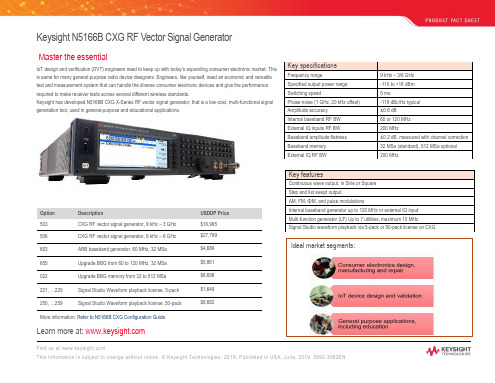
9 kHz – 3/6 GHz -110 to +18 dBm 5 ms -119 dBc/Hz typical ± 0.6 dB 60 or 120 MHz 200 MHz ± 0.2 dB, measured with channel correction 32 MSa (standard), 512 MSa optional 200 MHz
655
Upgrade BBG from 60 to 120 MHz, 32 MSa
022
Upgrade BBG memory from 32 to 512 MSa
221, …229
Signal Studio Waveform playback license, 5-pack
250, …259
Signal Studio Waveform playback license, 50-pack
• Wanted signal (desired CW or modulation signals) • Blocking signal • Modulated interference signal
Also Need a Signal Analysis Solution?
Try Keysight N9000B CXA signal analyzer as a companion to your N5166B CXG signal
Keysight N5166B CXG RF Vector Signal Generator
Master the essential
IoT design and verification (DVT) engineers need to keep up with today’s expanding consumer electronic market. This is same for many general-purpose radio device designers. Engineers, like yourself, need an economic and versatile test and measurement system that can handle the diverse consumer electronic devices and give the performance required to make receiver tests across several different wireless standards. Keysight has developed N5166B CXG X-Series RF vector signal generator, that is a low-cost, multi-functional signal generation tool, used in general-purpose and educational applications.
射频发生器原理

射频发生器原理
射频发生器是一种能够产生射频信号的设备,其原理基于振荡电路的工作原理。
射频发生器的振荡电路通常由放大器、反馈网络和一个频率稳定的谐振元件(如LC电路)组成。
在振荡电路中,放大器起到稳定频率和提供放大信号的作用。
它接收来自反馈网络的信号并进行放大,然后将放大后的信号输送回反馈网络。
反馈网络将一部分放大的信号反馈到放大器的输入端,使得电路能够维持振荡。
频率稳定的谐振元件(如LC电路)用于控制振荡电路的频率。
在谐振元件中,电感和电容以特定的方式连接,形成一个共振回路。
当反馈信号通过谐振元件时,只有特定频率的信号才能得到放大并继续在回路中循环,其他频率的信号则会被抑制或衰减。
通过调节谐振元件中的电感或电容值,可以改变振荡电路的频率。
这样,射频发生器就可以产生不同频率的射频信号。
射频发生器在无线通信、广播、雷达等领域有着广泛的应用。
它能够提供稳定而可靠的射频信号,为这些应用提供必要的工作频率。
安捷伦信号发生器选购指南
PSG 嵌入式软件 Signal Studio 软件
用户数据
I/Q 波形
Baseband generation tools
用于波形捕获和回放的 Baseband Studio 软件
用于衰落的 Baseband Studio 软件
I/Q 波形
RF/MW Signal Generation
模拟和数字 I/Q 信号
信号创建工具 (如 Signal Studio) 能够简化复杂信号的仿真过程。基带信 号生成工具 (如MXG配备的内部基带信号发生器) 将比特流转换为低频的IQ信 号,然后用 ESG,MXG 或 PSG 矢量信号发生器将 IQ 信号上变频为射频频率 或微波频率的信号。
Signal creation tools
Frequency coverage for Agilent spectrum and signal analyzers 9 kHz 1 GHz 3 GHz 6 GHz 9 GHz 40 GHz
67 GHz
2
安捷伦信号创建和生成模型
安捷伦信号生成方案包括三个主要部分: 信号创建,生成基带信号和生成 射频 / 微波信号。
安捷伦信号发生器选购指南
安捷伦信号发生器 — 为你量身定制测试解决方案
安捷伦信号发生器的优异性能和多种测量应用软件能让你在测试中更加自 信。安捷伦的信号源解决方案可以根据你的应用需求量身定制,用于研发,自 动化制造,便携式装置或设备维修。这篇选购指南纵向比较了不同信号源的性 能,可以帮你迅速找到最适合的安捷伦产品。
N9310A (9 kHz-3 GHz) N5181A/N5161A (100 kHz-6 GHz) E4428C (250 kHz-6 GHz) N5183A (100 kHz-40 GHz) E8257D (250 kHz-67 GHz) E8663D (100 kHz-9 GHz) N5182A/N5162A (100 kHz-6 GHz) E4438C (250 kHz-6 GHz) E8267D (250 kHz-44 GHz) N5106A 基带信号发生器
射频矢量信号分析仪

射频矢量信号分析仪
佚名
【期刊名称】《今日电子》
【年(卷),期】2009(0)7
【摘要】2820A型射频矢量信号分析仪能在400MHZ~4GHz或400MHz~
6GHz的频率范围内提供40MHzN信号采集带宽。
2820A具有快速频率开关,可以在250“S内调谐到一个新的频率;它具有高速数据传输率,新的技术允许通过UsB总线从仪器到PC传输大量的调制后的I、Q数据,速度超过了100Mb/s;2820A还具有快速序列测试、超低相位噪声的优点,在2GHz载波300kHz偏置下,相位噪声小于140dBc/Hz,这让20MHZWLAN802.11nN量时的EVM 测量的动态范围低至-48dB。
【总页数】2页(P68-69)
【关键词】矢量信号分析仪;射频;数据传输率;低相位噪声;频率范围;UsB总线;信号采集;Mb/s
【正文语种】中文
【中图分类】TN92;V355.1
【相关文献】
1.艾法斯推出全新S系列数字信号发生器(6GHz)和矢量信号分析仪(13GHz)全新一代提供高性能数字调制解调能力的中档价位台式触摸屏射频测试仪表系列[J],
2.NI最新推出6.6GHz PXI Express射频矢量信号分析仪和矢量信号发生器--新
型射频模块化仪器和PXI Express机箱为用户提供快捷灵活的无线测量功能 [J], 无
3.6.6GHz PXI Express射频矢量信号分析仪和矢量信号发生器 [J],
4.6.6GHz PXI Express射频矢量信号分析仪和矢量信号发生器 [J],
5.NI推出6.6GHz PXI Express射频矢量信号分析仪和矢量信号发生器 [J],因版权原因,仅展示原文概要,查看原文内容请购买。
1445B 通信矢量信号发生器 产品手册说明书

1445B通信矢量信号发生产品综述1445B通信矢量信号发生器作为一款通用的射频矢量信号源,频率范围覆盖100kHz~6GHz,具有优良的频谱纯度和功率输出指标;支持CW信号、模拟与数字调制信号、全制式的通信标准信号以及NB-IoT、WiFi和蓝牙信号发生功能,支持用户自定义基带数据信号发生。
1445B既是理想的本振源和时钟源,也是高性能的矢量信号源,优良的信号质量可进行物联网模组、基站和射频元器件的研发、生产与认证等,适用于教学实验、航空航天、移动通信、国防军工及雷达天线等众多领域。
主要特点⚫频率覆盖范围:100kHz~6GHz;⚫功率输出范围:-120 dBm~+20 dBm;⚫蜂窝网通信标准信号:NB-IoT/IoT-G/5G NR/TDD-LTE/FDD-LTE/TD-SCDMA/WCDMA/GSM/EDGE,为高质量移动通信物联网设备测试提供全面的解决手段;⚫非蜂窝网通信标准:WiFi802.11a/g/j/n/ac、蓝牙、LoRa;⚫丰富的数字调制格式:BPSK、QPSK、OQPSK、8PSK、16QAM、32QAM、64QAM、128QAM、256QAM等数字调制格式,用户可灵活配置不同调制方式及码元速率;⚫模拟调制功能:幅度调制、相位调制、频率调制、脉冲调制;⚫GPIB、LAN和USB等丰富程控接口,方便用户实现远程控制及网络升级。
基本功能数字调制数字调制是现代通信的重要方法,1445B可输出多种数字调制信号。
通信标准制式信号发生无线通信标准制式都具有标准的物理层结构,可根据标准产生各类标准制式信号。
NB-IoT标准信号发生5G NR标准信号发生LTE标准信号发生TD-SCDMA标准信号发生GSM标准信号发生物联网模块测试1445B可与5264B通信矢量信号分析仪组成物联网模组测试系统,支持WiFi、蓝牙和NB-IoT信号发生功能,可与物联网模组建立非信令连接,进行相应的射频测试及业务测试。
射频信号发生器 硬件原理

射频信号发生器硬件原理射频信号发生器是一种用于产生射频信号的仪器,广泛应用于无线通信、雷达、电视、无线电等领域。
它的硬件原理主要包括振荡电路、放大电路和控制电路等部分。
射频信号发生器的振荡电路是实现信号产生的关键。
振荡电路通常采用谐振电路,通过谐振元件(如电感、电容)和放大元件(如晶体管、场效应管)构成。
当谐振电路中的能量损耗和放大元件的增益满足一定条件时,振荡电路就能稳定地产生射频信号。
放大电路是为了增强振荡电路产生的信号。
射频信号发生器通常需要输出高幅度的射频信号,因此需要在振荡电路的基础上增加放大电路。
放大电路可以采用多级放大的方式,通过级联放大器来增加信号的幅度。
在放大过程中,需要注意控制增益和频率特性,以确保输出信号的稳定性和准确性。
射频信号发生器还配备了控制电路,用于调节和控制输出信号的频率、幅度和相位等参数。
控制电路通常由微处理器或者可编程逻辑器件实现,通过用户界面或者远程接口与用户进行交互。
用户可以通过操作控制电路来设置所需的信号参数,并监测当前的输出状态。
在实际应用中,射频信号发生器的硬件原理还涉及到其他一些关键技术。
例如,为了提高输出信号的纯度和稳定性,通常需要采用频率合成技术来消除非线性谐波和杂散信号。
此外,为了适应不同的应用需求,射频信号发生器还需要具备宽频带、高分辨率和快速切换等特性。
总结起来,射频信号发生器的硬件原理包括振荡电路、放大电路和控制电路等关键部分。
振荡电路实现了信号的产生,放大电路增强了信号的幅度,控制电路用于调节和控制信号的参数。
在实际应用中,还需要考虑其他技术以提高信号的纯度和稳定性,并满足不同应用的需求。
通过合理设计和优化硬件原理,射频信号发生器能够稳定、可靠地产生各种射频信号,为无线通信和电子设备提供可靠的信号源。
Keysight X-Series RF信号生成器技术数据手册说明书

T E C H N I C A LO V E R V I E W X-Series RF Signal GeneratorsN5181B/N5171B AnalogN5182B/N5172B/N5166B Vector–9 kHz to 6 GHz frequency range–Industry-leading performance–Sophisticated real-time applications–Low cost of ownershipSummary of Key SpecificationsMXGEXGCXGFrequency ranges9 kHz to 6 GHz 9 kHz to 6 GHz 9 kHz to 6 GHz Phase noise at 1 GHz, 20 kHz offset –146 dBc/Hz –122 dBc/Hz –119 dBc/Hz Spurious at 1 GHz (nonharmonics)–96 dBc –72 dBc –72 dBc Output power at 1 GHz+27 dBm +27 dBm +18 dBm ACPR (vector) W-CDMA 64 DPCH –73 dBc –73 dBc –73 dBc EVM (vector) 802.11ac/LTE 0.4 percent 0.4 percent 0.4 percent Bandwidth (vector)160 MHz 160 MHz 120 MHz Arbitrary waveform memory (vector)1024 MSa512 MSa512 MSaIndustry-leading performanceFrom 9 kHz to 6 GHz, the analog and vector MXG, EXG, and CXGsignal generators deliver unmatched performance in five key categories: phase noise and spectral purity, bandwidth, EVM, ACPR, and output power.Advanced real-time applicationsPerform advanced receiver testing compatible with the latest standards using the MXG or EXG and PathWave Signal Generation software: define signal parameters, transfer them to the instrument, and use closed-loop or interactive control during signal generation.Lower cost-of-ownershipX-Series signal generators are designed for high reliability and simplified service. One key example is the self-maintenance strategy: if onsite repairs are ever needed, they can be completed in less than two hours with our parts exchange program./find/X-Series_SGGenerate True PerformanceTo know your device’s behavior, you’ll take many paths. That’s the idea behind the Keysight Technologies. Inc. X-Series signal generators. They produce the signals you need—from simple to complex, from clean to dirty—to test your design within and beyond its limits.The X-Series is crafted to create signals capable of testing your very best devices. From the pure and precise MXG to the cost-effective EXG and general-purpose CXG, the X-Series helps you generate true performance.To help you quickly create signals that meet the needs of specific standards andmeasurements, the X-Series signal generators are compatible with Keysight PathWave Signal Generation software. Its suite of signal-creation tools addresses cellularcommunications, wireless connectivity, audio, video, positioning, tracking, and general-purpose applications.To reduce cost of ownership, the X-Series signal generators are designed for high reliability and fast, easy calibration, service, and repair. Today’s X-Series signalgenerators leverage technology used in previous-generation MXG signal generators, which are among the most reliable signal sources ever offered by Keysight.The CXG and MXG/EXG provide modulation bandwidths to 120 or 160 MHz, respectively. This wide modulation bandwidth is available with EVM up to 0.4 percent and flatness up to ± 0.2 dB, ample performance for even the most demanding design tasks.The X-Series achieves this combination of bandwidth and accuracy through the use of a proprietary baseband ASIC and a factory-calibrated channel correction technique that extend from the baseband I/Q modulator to the RF output. Together, these technologies minimize I/Q errors to provide high modulation accuracy plus wide modulation bandwidth without user intervention such asmanual I/Q adjustment.Take Your Devices to the Limit Pure and precise MXGOn the path to better performance, the pure and precise MXG X-Series signal generators are fine-tuned to be your “golden transmitter” in R&D. Whether you’re pushing for a linear RF chain or an optimized link budget, the analog and vector MXG models deliver the performance and capabilities you need: phase noise, ACPR, channel coding, and more.Use the MXG to test radar receiver sensitivity, characterize ADC or mixer SNR, or find receiver out-of-band rejection capability. You’ll get excellent results with industry-leading phase noise of –146 dBc/Hz at 1 GHz and spurious performance of –96 dBc at 1 GHz. You can also drive power amplifiers and characterize nonlinear behavior with industry-leading output power of +27 dB and ACPR of –73 dBc (W-CDMA test mode 1, 64 DPCH).With EVM up to 0.4 percent (802.11ac and LTE) and factory-equalized 160 MHz RF bandwidth with flatness of less than ± 0.2 dB, the MXG enables testing andcharacterization of multicarrier power amplifiers or wideband receivers and components, such as those used in 802.11ax WLAN designs.The MXG implements a newtriple-loop phased-lock loop (PLL) design and “frequency plan” that results in substantial phase noise improvements close to the carrier and at wide offsets. The frequency plan addresses several keyattributes: the choice of oscillator and reference frequencies in the synthesizer and the associated frequency conversion (mixers and multipliers) and filtering.The triple-loop approach allows optimized frequency spacing that ensures effective filtering of nonlinear artifacts such as images by pushing them outside the bandwidth of the synthesizer circuits. In the MXG, the planarranges the frequency references and conversions such that the largest are far from the desired frequencies and modest filtering can heavily attenuate the remainingspurious signals.Meet your toughest requirements The MXG is designed to keep pacewith your ongoing search for greater performance. In consumer wireless, military communications, or radar, performance gains can help you mitigate interference, accelerate data throughput, or enhance receiver sensitivity.Overcome interference problems In wireless, interference mitigationis becoming more difficult with the proliferation of users, devices, and standards. In the development of power amplifiers, the MXG helps minimize interference with less distortion by providing –73 dBc ACPR (W-CDMA test model 1, 64 DPCH) and +27 dBm output power.Accelerate data throughputMeeting throughput expectations atthe edge of the network is becomingmore challenging with LTE-Advancedand 802.11ac WLAN. With 160-MHzbandwidth and EVM up to 0.4 percent, theMXG helps you keep pace with presentand emerging standards.Enhance receiver sensitivityWith the latest generation of radarsystems, the challenge is to locate small,low-mobility targets—and one of thekeys is enhanced receiver sensitivity.By providing unsurpassed phase noiseof –146 dBc/Hz (1 GHz, 20 kHz offset)and spurious of –96 dBc (1 GHz) theMXG makes it possible to see the trueperformance of advanced radar systems.Optimize for Manufacturing TestCost-effective EXGOn the path to faster throughput and greater uptime, the cost-effective EXG is optimized for manufacturing test. Analog and vector models provide the signals you need for basic parametric testing of components, functional verification of receivers, and virtually anything in between.Accurately verify performance fastCheck component performance with +27 dBm output power and –73 dBc ACPR(W-CDMA test model 1, 64 DPCH). With 900-µs simultaneous switching of frequency, power, and waveform type, you can also maximize test throughput.Reduce total cost of testTo help you manage costs, the X-Series is scalable: buy the performance andcapabilities you need today and easily upgrade later. You can also purchase only the waveforms you need with 5-pack and 50-pack licensing.When space is at a premium, the EXG is just 2U high and offers options such as an integrated multi-function generator and a USB power-sensor interface.To reduce your total cost-of-ownership, the X-Series is designed for high reliability as well as fast, easy, and cost-effective calibration, service, and repair. To maximize uptime, today’s X-Series signal generators leverage technology used in the previous-generation MXG, which has a mean timebetween failures (MTBF) of 116,000 hours.To help you minimize downtime and service costs, the X-Series signal generators include advanced self-maintenance capabilities such as full internal root-causeself-diagnostics. The recommended three-year calibration cycle and self-maintenance strategy will help reduce support costs and increase instrument uptime. If onsite repairs are ever needed, they can be completed in less than two hours (and no post repair calibration needed) with our parts exchangeprogram.Generate all emerging IoT signalsIoT and general-purpose R&D and design validation (DVT) engineers need to keepup with today’s expanding consumer electronics market. Engineers need a golden transmitter test system that can simulate different wireless standards at a price that falls within budget. The new CXG provides great all-around performance, while also being standards-compliant, to meet the needs of engineers designing outstanding IoT and general-purpose devices.Meet your budget constraintsTo help you manage costs, CXG provides excellent RF performance, and the most common used capabilities in a low-cost of ownership for engineers, designing general purpose devices, consumer electronics devices, or for educators in teaching labs. You can also purchase only the waveforms you need with 5-pack and 50-pack licensing.Easily Migrate from the ESG or First-Generation MXGIf you’re already using the ESG or a first-generation MXG, we’ve made it easy to migrate to the new MXG and EXG.The new MXG exceeds ESG performance in every important category. It also provides a larger set of applications that cover the latest standards. In automated test systems, extensive backward compatibility enables drop-in replacement without rewriting code or integrating new drivers.Compared to the first-generation MXG, the EXG provides similar performance and significant enhancements. It starts with an attractive entry price and more capability in areas such as output power, ACPR, bandwidth, and memory. To meet evolving test requirements, you can scale up EXG performance and capability as needed: add higher output power, a real-time baseband generator, or a built-in multi-function generator.For more information go to: /find/ESG2MXGWorking on classified or high-security projects poses additional challenges. When your instrument needs to be removed or shared, you need to be confident that sensitive information is not accessible.Option 006 for the MXG and EXG signal generators provides removable external memory, including memory management features to erase and sanitize all memory locations inside the instrument.Option SD0 disables any file storages to the instrument’s internal non-volatile memory as well as removing any physical drives. Do note that option SD0 is not compatible withoption 009 and 660.Extend Frequency to New Unlicensed BandThe frequency extender offers asmooth migration for existing MXG/EXG to catch up with the latest testrequirements. It provides a single RFoutput for full frequency coveragefrom 9 kHz to 7.2 GHz and 160 MHzmodulation bandwidth.Work seamlessly with MXG/EXGControl from an MXG/EXG front panel as usual and automate the test systems using thesame SCPI commands via LAN, GPIB, or USB. Engineers can easily upgrade an existingMXG/EXG with power meter calibration at their site.Extend without scarifying performanceThe combination of MXG/EXG and the frequency extender provide up to +18 dBmmaximum output power. Generate an 802.11ax 160 MHz bandwidth signal at 7.2 GHz andachieve excellent EVM performance < -47 dB (0.45%) for output power up to +5 dBm.Simplify Signal Creation with PathWave Signal GenerationPathWave Signal Generation software offers two types of licenses: a PC license (N76xxAPPC) and a waveform playback license (N76xxEMBC).N76xxAPPC is PC based license which enables N76xxC software operating in full capabilitiesmode to generate and make a live connection to download signalwaveforms into the signal generators or an AWG. N76xxAPPC is typically recommended for R&D teams.N76xxEMBC is an embedded license that runs on a signal generator or an AWG, which enables you to playback signal waveforms off-line without a live connection to N76xxC software. N76xxEMBC is recommended for manufacturing teams or for pre-generated waveforms.Whether you’re working on a single radio format or integrating multiple formats into a single device, easy access to the right test signals streamlines validation and helps ensure interoperability. Accelerate your work with PathWave Signal Generation software, a flexible suite of signal-creation tools that reduces the time you spend on signal simulation. Its performance-optimized reference signals—validated by Keysight—enhance the characterization and verification of your devices.PathWave Signal Generation is scalable to meet a wide range of requirements in component and receiver testing. It starts with a choice of two operating modes: waveform playback mode and real-time mode. Waveform playback mode supports generated I/Q waveforms playback on a licensed instrument. Real-time mode provides advanced capabilities such as closed-loop control during signal generation. This level of flexibility helps you optimize the cost and capability of the PathWave Signal Generation configuration that’s right for you.PathWave Signal Generation covers the latest technologies such as 5G New Radio (NR), C-V2X, IoT, 802.11ax/ay WLAN, Bluetooth 5, and GNSS, and flexible digital modulation and delivers a wide range of applications in the following categories:–General purpose–Cellular communications –Wireless connectivity –Audio/video broadcasting–Detection, positioning, tracking, and navigation For more information, go to:/find/SignalStudioSimulate Real-World Signals with Real-Time ModeIn PathWave Signal Generation, real-time mode is used to define the parameters ofnonrepeating signals needed for receiver testing. Its graphical interface provides a direct instrument connection for parameter transfer and closed-loop or interactive control during signal generation. Real-time capabilities are currently available in versions of PathWave Signal Generation that address the following standards: –LTE/LTE-A FDD/TDD –W-CDMA/HSPA+ –GSM/EDGE/Evo –cdma2000® –GNSS–Digital video –Broadcast Radio –Real-time fadingReal-time generation supports creation of complex signal scenarios of extremely long durations. In satellite navigation applications, an MXG or EXG can generate up to 32 line-of-site and multipath channels with greater than 24 hours duration. In DVBapplications, this solution supports up to two hours of playback or continuous PN23 data sequences.Closed-loop testing is becoming increasingly important with the latest digital wireless standards, especially during throughput testing of real-world channels. In LTE/LTE-A applications, PathWave Signal Generation plus an X-Series signal generator supports full conformance testing with BTS loopback performance testing.Wanted, ULInterfererLTE receiver performance test with real-time signal generationThe replay of an arbitrary waveform file is often an easier way to handle non-standard or classified signal-simulation applications. In such cases, an important but simpletechnical advance is deep waveform memory: the MXG has up to 1 GSa and the EXG has up to 512 MSa.With 1 GSa, the MXG can provide a minimum of five seconds and as much as hours of a continuous signal without repeating, depending on sample rate. This capability can, in some cases, provide an alternative to real-time signal generation.Note: The MXG and EXG X-Series analog signal generators have the same connector layout.Easily save and recall instrument setups from the front panel.50 W reverse powerprotection.to four Keysight USB power sensors via USB 2.0 (Type-A port).for inputs such as sweep triggering or outputs such as source settled, pulse video, or pulse synchronization.inputs for composite analog modulation of AM or FM/PM, or digitally sum with multi-function generator Option 303.drive with instrument security (Option 006).files remotely over1000Base-T LAN, GPIB, or USB (Type-B port).Note: The MXG and EXG X-Series vector signal generators have the same connector layout.Easily save and recall instrument setups fromthe front panel.50 W reverse powerprotection.to four Keysight USB power sensors via USB 2.0 (Type-A port).Analog I/Q inputs.Configure BB TRIG 1, 2, or EVENT 1 or PAT TRIGconnectors for baseband I/O signals such as pattern/frame synchronization trigger input for BER testing.Stimulate baseband I/Q systems with standard single-endedanalog I/Q outputs or differential (Option 1EL).drive with instrument security (Option 006).real-time signaling inputs such as HARQ, TPC, or timing adjustments for HSPA, LTE, and more.Related LiteraturePublication name Publication number MXG X-Series Signal Generators N5181B Analog & N5182B Vector – Data Sheet5991-0038EN MXG X-Series Signal Generators N5181B Analog and N5182B Vector - Configuration Guide5990-9959EN EXG X-Series Signal Generators N5171B Analog & N5172B Vector - Data Sheet5991-0039EN EXG X-Series Signal Generators N5171B Analog & N5172B Vector - Configuration Guide5990-9958EN PathWave Signal Generation Software Simplify Signal Creation - Brochure5989-6448ENN5166B CXG Vector Signal Generator - Data Sheet5992-3959ENN5166B CXG RF Vector Signal Generator - Configuration Guide5992-4077EN。
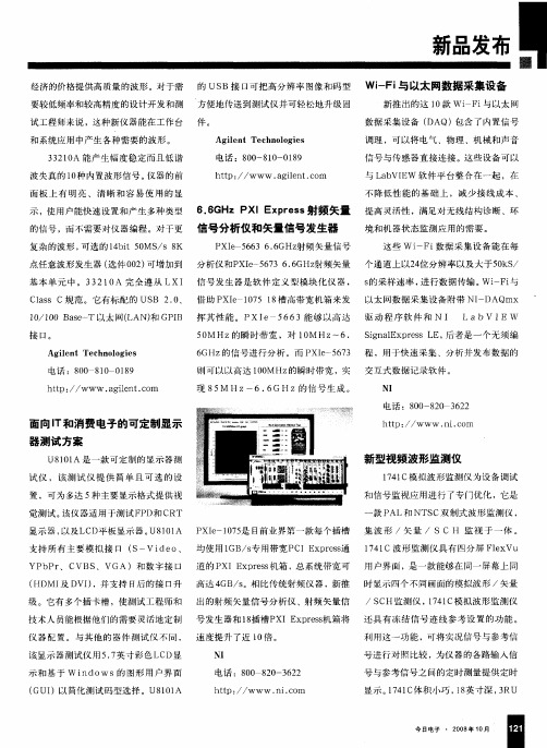
6.6GHz PXI Express射频矢量信号分析仪和矢量信号发生器
电 话 :8 0 1 0 8 0 8 0 1 9
htpt t , .g l n . o a ie t c r n
电话 :8 0 8 0 6 2 0 — 2 3 2
面向 l 和消费 电子 的可定制显示 T 器测试方案
U8 0 A 是 一 款 可 定 制 的 显 示 器测 11
1/l 0 B s-T以 太 网 ( AN) GP B 挥 其性 能 。PxI 5 63能够 以 高达 驱 动程 序 软 件 和 N 0 0 ae L 和 I e 6 I LabV I E w
接 口。
Ag l n ie t Tec n l g e h oo i s
羽口及仰 新品发布 I 口
经 济的价格 提供高 质量的波 形 。对于 需 的 US B接 E可把 高分辨率 图像 和码 型 l 要较低频率和较 高精度 的设计开发和 测 方便地传送 到测试仪并 可轻松地升级 固 试工程 师来说 ,这种新 仪器能 在工作 台 件 。
Wi F 与以太网数据采集设备 - i
新 推 出的这 1 款 wi i 0 F 与以太 网
数据采集 设备 ( DAQ) 含 了内置信号 包 调理 ,可 以将 电气、物 理 、机械 和声音 信号 与传感 器直 接连接 。这些设 备可以
与 L b E 软 件平 台整合在一 起 ,在 a VI W 不降 低性 能的 基础 上 ,减 少 接线 成本 、
h t ,, tp
. .o nic m
新型视频波形监测仪
1 4 拟波形监 测仪为 设备调试 1 7 C模
和信 号监视应 用进行 了专 门优 化 ,它是
一
试仪 ,该 测试 仪 提 供 简单 且 可 选 的设
置 ,可为适 用于测试 F D和 C P RT
无源器件产品和技术介绍

300GHz频率
中国联通CDMA:825-835,870-880MHz
3GHz
1990MHZ
1850-1910 , 1930-
中国联通GSM: 909-915,954-960MHz
中国移动GSM: 890-906,935-954MHz
DCS: 1710-1785,1805-1880MHZ
数字集群通信: 806-824MHZ
PART 1
Thanks
滤波器
PORT3
双工器
Antenn a
三、功分器基本知 识介绍
分类
基本参数介绍
1. 插损 2. 理想分配损耗(dB)
=10 log(1/N) ① (N—功率分配分
路数)
理想分配损耗
N=2 N=3 N=4 N=8 N=16
3.0 dB 4.8 dB 6.0 dB 9.0 dB 12.0 dB
01
PHS:
1900-1915MHz
3G: WCDMA,CDMA2000,TD-SCDMA
无线接入:2.4G,3.5G, 5.8G
无源器件产品型号命名
MB800-DUP-B10 (M10,R10) 功分器
MB800-PS1/4-N-JJ
MB800/900-LC50D
双工器,滤波器 MB800-FIL-B15 MB800-PS1/2-D-KK 避雷器 MB1800-LC50DA
射频产品和技术介绍
djust the spacing to adapt to Chinese typesetting
Your name
二、滤波器基本知识介 绍
分类 公司现有射频器件产品 射频器件产品型号命名 滤波器分类 滤波器基本参数介绍
矢量信号发生器的原理

矢量信号发生器的原理矢量信号发生器是一种可以产生复杂的高频信号的设备,其核心部件主要由本振源、控制单元和调制器组成,通过这些部件协同工作,生成包含多个频率和相位信息的复杂矢量信号。
该设备广泛应用于通信电子、雷达电子、移动通讯、卫星通信等领域。
矢量信号发生器的基本构成矢量信号发生器一般由以下三个部分组成:本振源本振源是该设备的核心部分,主要作用是提供基本的高频信号,构成复杂的矢量信号的基础。
在本振源中,借助于一些高精度的示波器和信号源,在高速运动的环境下,可以保证信号的稳定和精确性。
控制单元控制单元中含有多个控制电路和PIC控制器,可以对本振源中的信号源进行控制,改变其频率和相位信息,生成符合规定的矢量信号。
调制器调制器是矢量信号发生器中非常重要的一个部分,它可以对信号进行多种处理,生成复杂的矢量信号,其主要功能有:•幅度调制通过对信号的幅度进行调制,来改变信号的强度和高低音,产生各种各样的语音、音乐信号。
•相位调制通过改变信号的相位,来调节信号的频率,产生不同的音高和音调。
•频率调制通过改变信号的频率,来产生不同的信号类型和调制方式。
矢量信号发生器的工作原理矢量信号发生器的工作原理是基于混频技术进行的。
当本振源提供完整的信号时,电源会先将其分为两路信号,一负责调制,一负责混频。
当信号经过调制器后,通过线性变换器进行基带信号调制,改变其频率和相位信息,使其生成复杂的矢量信号。
而当另一个信号通过混频器后,会加上一个载频信号,并与基带信号相乘,最终得到矢量信号。
矢量信号发生器的应用矢量信号发生器在现代通信领域中具有非常广泛的应用,具体表现在以下几个方面:移动通信矢量信号发生器可以模拟各种运营商网络,生成生产级别的CDMA、GSM、3G 和4G技术的信号,用于移动手机和基站的测试和验证。
卫星通信在卫星通信领域中,矢量信号发生器可以模拟卫星信道,测试卫星天线的指向和接收性能、高速数据传输和电路测试。
雷达电子矢量信号发生器可以生成多宽带信号,用于雷达信号仿真,比如多波束雷达、电子对抗和干扰测试等。
射频基础知识及其主要指标

长波
10~1千米 (km)
6
中 频(MF) 300~3000千赫 (kHz)
中波
1000~100米 (m)
7
高 频(HF)
3~30兆赫 (MHz)
短波
100~10米 (m)
8
甚高频(VHF) 30~300兆赫 (MHz)
米波
10~1米 (m)
9
特高频(UHF) 300~3000兆赫(MHz)
分米波
10~1分米 (dm)
3~30赫 (Hz)
极长波
100~10兆米 (Mm)
2
超低频(SLF)
30~300赫 (Hz)
超长波
10~1兆米 (Mm)
3
特低频(ULF)
300~3000赫 (Hz)
特长波
1000~100千米 (km)
4
甚低频(VLF)
3~30千赫 (kHz)
甚长波
100~10千米 (km)
5
低 频(LF)
30~300千赫 (kHz)
Comba Telecom Systems
接收机的热噪声功率电平(底噪)
任何一个无线通信接收机能否正常工作,不仅取决于所能获得的输入
信号的大小,而且也与其内部噪声以及外部噪声和干扰的大小有关。
接收机内部噪声也称为热噪声,它是由电子运动所产生的,其定义是
指当温度为290°K(17°C)时,由接收机通带(通常由接收机中频带
射频基础知识 及其主要技术指标
京信通信系统华东分公司
2021年3月31日
Comba Telecom Systems
射频基础知识 及其主要指标
1.有源系统 2.天馈系统 3.无源器件
Comba Telecom Systems
射频发生器的工作原理

射频发生器的工作原理嗨,小伙伴们!今天咱们来唠唠射频发生器这个超酷的玩意儿。
你可别一听名字就觉得它很神秘,其实呀,理解它的工作原理就像揭开一层有趣的面纱一样。
射频发生器呢,简单来说就是一个能产生射频信号的设备。
那射频信号是啥呢?就像是一种特殊的电波,频率比我们平常听到的广播信号频率高很多哦。
想象一下,它就像一个超级活跃的小精灵,在一个特定的频率范围内蹦跶。
咱们先从它的内部构造说起。
射频发生器里面有一个很关键的部分叫振荡器。
这个振荡器就像是一个心脏,它不停地跳动,产生出有规律的电信号。
你可以把它想象成一个小鼓手,按照自己独特的节奏敲打出电波的节奏。
这个节奏就是射频信号的频率啦。
比如说,有的射频发生器的振荡器能产生出13.56兆赫兹的频率,这就像小鼓手每分钟敲13.56万次鼓点一样,是不是很神奇呢?有了这个基础的电信号还不够哦。
射频发生器还得把这个信号变得更强大、更有用。
这时候就轮到放大器出场啦。
放大器就像是一个大力士,把振荡器产生的微弱信号用力一推,让它变得强壮起来。
就好比把小鼓手的微弱声音通过一个大喇叭放大,这样就能传播得更远啦。
这个放大后的射频信号就可以用来做各种各样有趣的事情啦。
那射频发生器产生的射频信号能干啥呢?用处可多着呢!在通信领域,它就像是一个快递员。
比如说你的手机要发送信息,射频发生器产生的信号就会把这个信息像包裹一样,快速准确地送到基站那里。
它就像在空气中开辟了一条无形的高速公路,让信息在上面欢快地奔跑。
在医疗领域,射频发生器也有它的大舞台。
它可以产生射频能量,用来治疗一些疾病呢。
比如说,在治疗某些肿瘤的时候,射频发生器就像一个精准的小战士。
它产生的射频信号能够聚焦到肿瘤部位,然后释放能量,把肿瘤细胞像小怪兽一样消灭掉。
这时候的射频发生器就像是带着超能力的英雄,拯救患者的健康。
还有在工业上,射频发生器也没闲着。
它可以用于加热材料。
想象一下,有一块金属材料需要加工,射频发生器产生的射频信号就像无数个小火苗,均匀地加热着这块金属。
射频信号发生器的基本组成
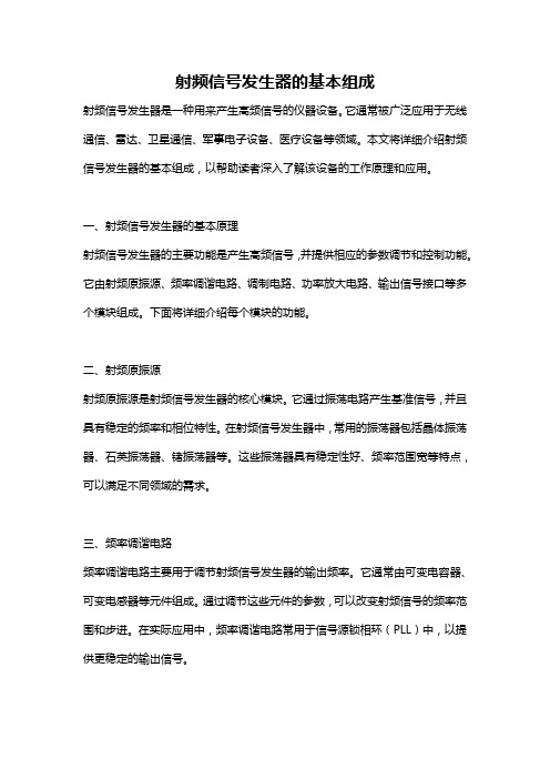
射频信号发生器的基本组成射频信号发生器是一种用来产生高频信号的仪器设备。
它通常被广泛应用于无线通信、雷达、卫星通信、军事电子设备、医疗设备等领域。
本文将详细介绍射频信号发生器的基本组成,以帮助读者深入了解该设备的工作原理和应用。
一、射频信号发生器的基本原理射频信号发生器的主要功能是产生高频信号,并提供相应的参数调节和控制功能。
它由射频原振源、频率调谐电路、调制电路、功率放大电路、输出信号接口等多个模块组成。
下面将详细介绍每个模块的功能。
二、射频原振源射频原振源是射频信号发生器的核心模块。
它通过振荡电路产生基准信号,并且具有稳定的频率和相位特性。
在射频信号发生器中,常用的振荡器包括晶体振荡器、石英振荡器、锗振荡器等。
这些振荡器具有稳定性好、频率范围宽等特点,可以满足不同领域的需求。
三、频率调谐电路频率调谐电路主要用于调节射频信号发生器的输出频率。
它通常由可变电容器、可变电感器等元件组成。
通过调节这些元件的参数,可以改变射频信号的频率范围和步进。
在实际应用中,频率调谐电路常用于信号源锁相环(PLL)中,以提供更稳定的输出信号。
四、调制电路调制电路是射频信号发生器中的重要模块。
它用于对射频信号进行调制,以满足不同的调制需求。
常见的调制方式包括幅度调制(AM)、频率调制(FM)、相位调制(PM)等。
调制电路通常由调制信号源、调制器、滤波器等元件组成。
通过调节这些元件的参数,可以实现不同类型和深度的调制。
五、功率放大电路功率放大电路用于增强射频信号的输出功率。
它通常由功率放大器、功率补偿器、功率控制电路等元件组成。
射频信号发生器的输出功率决定了其输出信号的幅度范围和覆盖距离。
功率放大电路通过增大输入信号的功率,以提高信号的传输距离和穿透能力。
六、输出信号接口输出信号接口是射频信号发生器与外部设备进行连接的接口。
它通常包括同轴接口、平衡接口、微带线接口等多种形式。
通过输出信号接口,射频信号发生器可以将产生的高频信号输出给其他设备,以实现数据传输、调试测试、测量分析等功能。
6.6GHz PXI Express射频矢量信号分析仪和矢量信号发生器

分 析 。 而 N XI IP e一5 7 6 3则 可 以 以 高 达 I O O MHz的 瞬 时 带 宽 ,
实 现 8 MH 5 z到 66 H .G z的 信 号 生 成 。 N X e 0 5是 业 界 中 I I 一17 P
第 一 款 每 个 插 槽 均 使 用 1 B s专 用 带 宽 P IE pes通 道 的 G/ C xrs
N X e一 6 366 H I I 5 7 .G z射 频 矢 量 信 号 发 生 器 , 将 借 助 于 N P 都 I
P I 一17 8槽 高 带 宽 机 箱 发 挥 其 性 能 。 N X e一 6 3能 Xe 051 I I 56 P
够 以高 达 5 MH 的 瞬 时 带 宽 , 1 MH 到 6 6 H 0 z 对 0 z . z的信 号 进 行 G
障 。利 用 L b n o sC I 件 开 发 的测 控 软件 采 用 a widw / V 软
了层 次化 和模 块化 的结 构 , 得 测试 效 率 得 到 极 大 地 使
提 高 , 且 易 于 软 件 的雏 护 和 扩 展 。 并
目标模 拟 转 台 系 统 是 模 拟 目标 运 动 的红 外 信 号
3 结 束 语
送工 控 机 分析 、 理 。信 号 检 测 组合 由插 在 10线 母 处 0
板上 的 1 0块 线路 板组 成 。其 中包括 程 控信 号源 板 、 频
鼎阳科技射频产品手册说明书
1目 录CONTENTS02 06 08 12 15 19 24 28 32 34 38 41 43 4649 56公司简介.......................................................................................................................................................................................................... 频谱分析仪SSA5000A 系列频谱分析仪................................................................................................................................................................... SSA3000X-R 系列实时频谱分析仪.................................................................................................................................................... SSA3000X PLUS 系列频谱分析仪..................................................................................................................................................... SHA850A 系列手持频谱分析仪.......................................................................................................................................................... 频谱&矢量网络分析仪SVA1000X 系列频谱&矢量网络分析仪........................................................................................................................................ 矢量网络分析仪SNA6000A 系列矢量网络分析仪....................................................................................................................................................... SNA5000A 系列矢量网络分析仪....................................................................................................................................................... SNA5000X 系列矢量网络分析仪....................................................................................................................................................... SHN900A 系列手持矢量网络分析仪.............................................................................................................................................. 射频/微波信号发生器SSG6000A 系列微波信号发生器....................................................................................................................................................... SSG5000A 系列微波信号发生器....................................................................................................................................................... SSG5000X 系列射频模拟/矢量信号发生器............................................................................................................................. SSG3000X 系列射频信号发生器....................................................................................................................................................... 探头及附件 其他探头及配件........................................................................................................................................................................................... 售后承诺........................................................................................................................................................................................................... 2通用电子测试测量仪器领域的行业领军企业公司战略Every Bench. Every Engineer. Every Day.深圳市鼎阳科技股份有限公司(简称“鼎阳科技”,股票代码:688112)是通用电子测试测量仪器领域的行业领军企业,A 股上市公司。
吉时利公司对其射频矢量信号发生器进行功能升级
吉时利公司对其射频矢量信号发生器进行功能升级
朴立平
【期刊名称】《中国计量》
【年(卷),期】2009()11
【摘要】10月9日.美国吉时利仪器公司宣布对其射频矢量信号发生器产品线进行功能升级.降低了信号产生的时间并增强了信号质量。
吉时利新款2920A型射频矢量信号发生器可以支持比其他竞争系统更快的频率和幅度切换速率。
与一般的系统需要针对研发或生产分别进行优化不同.2920A型仪器是个具备成本效益的方案.在设计验证和生产测试阶段都能适用。
【总页数】1页(P42-42)
【关键词】矢量信号发生器;吉时利公司;功能升级;射频;美国吉时利仪器公司;竞争系统;信号质量;信号产生
【作者】朴立平
【作者单位】
【正文语种】中文
【中图分类】TN915.05;TM935
【相关文献】
1.吉时利推2910型射频矢量信号发生器 [J],
2.吉时利重拳出击升级其获奖产品——2910型射频矢量信号发生器 [J],
3.吉时利新升级射频矢量信号发生器产品 [J],
4.吉时利公司新的射频矢量信号发生器提供业界高吞吐量和低相位噪声的结合 [J],
5.吉时利升级其获奖产品——2910型射频矢量信号发生器 [J],
因版权原因,仅展示原文概要,查看原文内容请购买。
NI发布首台射频矢量信号收发仪重新定义射频测试

NI发布首台射频矢量信号收发仪重新定义射频测试
单祥茹
【期刊名称】《中国电子商情:基础电子》
【年(卷),期】2012(000)012
【摘要】今年的NIDays,除了展示涵盖从汽车、电力能源到国防与航空航天等五大领域的近50个热门产品和应用,更是推出了业界首台射频矢量信号收发仪(VST)NI PXIe-5644R。
【总页数】2页(P32-33)
【作者】单祥茹
【作者单位】《中国电子商情:基础电子》编辑部
【正文语种】中文
【中图分类】TN92
【相关文献】
1.NI发布首台射频矢量信号收发仪重新定义射频测试 [J], 单祥茹
2.全球首台射频矢量信号收发仪重新定义射频测试 [J], 无
3.NI宣布推出第二代矢量信号收发仪的基带版本,以应对最苛刻的收发仪测试应用[J],
4.软件引领射频与通信行业变革 NI携其基于LabVIEW RIO架构新一代矢量信号收发仪亮相第二届电子设计创新会议 [J],
5.软件引领射频与通信行业变革 NI携其基于LabVIEW RIO架构新一代矢量信号收发仪亮相第二届电子设计创新会议 [J],
因版权原因,仅展示原文概要,查看原文内容请购买。
矢量信号发生器

2. 矢量信号源主要用于产生矢量信号,即数 字通信中常用的调制信号,支持如l/Q 调制: ASK、FSK、MSK、PSK、QAM 、定制 I/Q, 3GPP LTE FDD 和 TDD、3GPP FDD/HSPA/HSPA+、GSM/EDGE/EDGE演进、 TD-SCDMA, WiMAX™ 等标准。对于矢量信号源 来说,由于其内带调制器,所以频率一般不会 太高(6GHz左右)。相应的其调制器的指标 (如内置基带信号带宽)和信号通道数一个重 要比较广谱的概念,通常意义 上说,能产生射频信号的信号源都可以叫作射 频信号源。当前的矢量信号源也多是射频波段 的,所以也称矢量射频信号源。这两者的区别 主要是: 1. 单纯的射频信号源只用于产生模拟射频单 频信号,一般不用于产生调制信号,特别是数 字调制信号。这类信号源一般频带较宽,功率 动态范围也大一些。
- 1、下载文档前请自行甄别文档内容的完整性,平台不提供额外的编辑、内容补充、找答案等附加服务。
- 2、"仅部分预览"的文档,不可在线预览部分如存在完整性等问题,可反馈申请退款(可完整预览的文档不适用该条件!)。
- 3、如文档侵犯您的权益,请联系客服反馈,我们会尽快为您处理(人工客服工作时间:9:00-18:30)。
I+Q
1
IQ
I/Q
1. I/Q
2.
I/Q
IQ I+Q ±100 mV ± 4 dB 0 – 50 dB ± 200 0.5V 50Ω 653 655
Keysight N5166B CXG
9 kHz 3 6 GHz
1 第 1
...................................................................................................................................................................... 3 ................................................................................................................................................................... 4 ................................................................................................................................................................... 5 ........................................................................................................................................................... 7 ........................................................................................................................................................... 8 ......................................................................................................................................................... 12 ................................................................................................................................................................. 19
≤ 5 ms < 12 ms
≤ 5 ms
≤ 5 ms < 12 ms
≤ 5 ms
±1 dB
20 µs
-15 dBm -144 dBm
3201
USB/LAN USB/GPIB
10000 LAN GPIB USB GPIB
“
”
6 第
6
SSB 5 250 MHz 250 MHz 500 MHz 1 GHz 2 GHz 3 GHz 4 GHz 5 GHz 6 GHz
N
9 kHz < 5 MHz
1
5 < 250 MHz
1
250 < 375 MHz
0.25
375 < 750 MHz
0.5
750 < 1500 MHz
1
1500 < 3000.001 MHz
2
3000.001 6000 MHz
4
≤ 5 ms
±
×
±
±
±
≤ ±5 ppm/10 < ±1 ppm/
± 4 × 10⁻⁸
0.3 3 kHz
CCITT N
+5 dBm
100 kHz 3 GHz
9 kHz 3 GHz > 3 4 GHz
< 0.01% < +4 dBm
< -35 dBc < -35 dBc
> 4 6 GHz
< -53 dBc > 10 kHz
9 kHz < 5 MHz
-65 dBc
5 250 MHz
-75 dBc
°C
0.01 dB
°C
0.01 dB
0.15 dB > 3 GHz
5 第
5
1
≤ 1.0 GHz > 1.0 2 GHz > 2 3 GHz > 3 4 GHz > 4 6 GHz
1. SWR < 1.60:1
30 kHz
< 1.3: 1 < 1.55: 1 < 1.8: 1 < 1.5: 1 < 1.9: 1
12
UNT
3
ΦM
12
“
”
N
N × 10 MHz
0.025% 1 Hz
< ± 2% + 20 Hz 1 kHz
N x 50 kHz
1 dB
/5 Hz 3 MHz
3 dB
/1 Hz 7 MHz
<
±0.2% + (N × 1 Hz)1
<
±0.06% + (N × 1 Hz)
2
< [1 kHz
N x 50 kHz] 0.4%
20 kHz -116 dBc/Hz -130 dBc/Hz -125 dBc/Hz -119 dBc/Hz -112 dBc/Hz -107 dBc/Hz -106 dBc/Hz -105 dBc/Hz -103 dBc/Hz
FM 5 MHz 6 GHz
AM
300 Hz 3 kHz < N x 2 Hz
10 ns
0 42 s –
– 10 ns
500 ns 42 s –
– 10 ns
0 42 s –
1+
2 – 10 ns
20 ns 42 s –
1+
2 – 10 ns
N5180320B
2047
/
20 ns 42 s
1.
< +10 dBm
11 第
11
IQ
1
IQ I/Q I/Q
I/Q I/Q I/Q
I/Q I/Q I/Q
+1V
50Ω/600Ω/1MΩ
FM
12
“
”
N
NX5
N X 0.5
3 dB
1 MHz
3 dB
4 MHz
0.1%
<+0.5% + 0.01
[1 kHz
]
<
[1 kHz
] 0.2%
+1V
50Ω/600Ω/1MΩ
ΦM
12
1.
DCFM
2.
DCFM
3.
FM
5 MHz
±5°C
8 第
8
UNT
1 KHz
< 80%
1 KHz
2 第 2
0 55°C
2
45
80%
95% 25℃
20 30°C
50 Ω
IoT
25℃
N5166B CXG X
N5166B CXG
3 第
3
1
23
SCPI
/
503 506 0.001 Hz
1 1 2 3 4 5 6
9 kHz 5 MHz I/Q 9 kHz 5 MHz I/Q
3 GHz 6 GHz
0.1°
FM ΦM
I/Q
AM FM
AM FM ΦM
AM
FM
ΦM
I/Q
I/Q
AM
+
+
+
+
+
+
FM
+
+
-
+
+
+
ΦM
+
-
+
+
+
+
+
+
+
-
+
+
I/Q
+
+
+
+
-
+
I/Q
+
+
+
+
+
-
“+”=“-”=Fra bibliotek9 第
9
AM FM ΦM 1 2
I
UNT AM FM ΦM
303 303 7 5
1 2
AM FM ΦM AM FM ΦM
SONET/SDH 155 MB/s 622 MS/s 2488 MB/s
100 Hz –1.5 MHz 1 kHz – 5 MHz 5 kHz – 20 MHz
µUI rms 140 67 271
0.9 ps 0.11 ps 0.11 ps
1.
+10 dBm
7 第
7
UNT
100 KHz
DCFM
FM
GPIB LAN USB
6 < 3.3 ms
0.1 ppm 6
SCPI
100 Hz