ALM-Ⅱ 双通道空燃比分析仪说明书
Sauermanngroup SI-CA 120 120 220 320 燃料分析仪快速启动指南说明

SI-CA 120 / SI-CA 220 / SI-CA 320Quick Start Guide+ZERO the pressure sensorUpdates the measureSaves the current measurement oranalysis in the memory location selectedfrom the ‘Select Memory’ menuStarts the report ticketEnters the Print menuStops the flue gas analysisEnters the modify mode for the selectedOK Confirms the settingsCancels the change/operation andreturns to the previous screenZooms the screenShows the details for the selected‘Find’ function; starts a quick search forthe analysis to recallUsing the Flue Gas AnalyzerBe sure all connections are tight to assureDuring autozero DO NOT insert the gas probein the chimney.Keep pressed for 2 seconds until it beepsAcquires the temperature value detected from the sampling probe. Thatvalue is reported inthe parameter ‘Air T’.It saves the value,acquired or enteredin the parameter‘Air T’.5 MemorySi-CA 120 :3 Select the required LanguagePress then go to 'Languages' withScroll through the available languages withandPress to set the selected language.4 Select the required Measurement UnitsPress , go to ‘Analysis’ then ‘Measurement units’ withScroll through the required parameter to set with andthen pressSelect the required unit with and then press2 ON / OFFIf 'Diagnostic Hardware' screen displays, pressThen, wait for Autozero to start.8 Measure Ambiant COIt is mandatory to perform the instrument autozero in fresh, clean outdoor air.Save themeasurement.Connect thegas probe tothe instrumentand perform themeasurement.Wait 5 minutes.In ‘Data logger’, the user can define the analysis, memoryselection and printingmodes.In ‘Select’ can beinserted all thecustomer data.Si-CA 220 & Si-CA 320 :6 Stop / Restart the Pump (Si-CA 120)While in manual analysis, holding pressed both keys andmakes the instrument switch off the suction fumes pump and blocks the refresh of any current measure. To switch on the suction fumes pump again and reactivate the refresh of thecurrent measure, press again the keys and7 Draft measurementOnce the pressure zeroingis completed insert theprobe in the chimney andmeasure the draft.View & Save theDRAFT measurement.Before zeroing the pressure it is mandatory to REMOVE the probe from the chimney.ZERO Draft SensorIn case the automatic print mode is set then the average analysis printing start automatically. Conversely, after the sampling of the third analysis, the average analysis is shown, so that it can be sent to the printer or downloaded as explained in the following.Xair = Excess airΔT = Differential Temperature (NET Temperature)Tg = Flue Gas Stack Temperature Eff. tot = Total Combustion Efficiency Ta = Ambient or Incoming Air Temperature Loss tot = Stack LossesTo view different test measurements, usekey to scroll through the various test measurement screens.Scan the QR code usingthe Si-CA QRCodeAppSauermann APP to downloadthe acquired data related tothe average analyses andthe additional measures, ifperformed.Automaticallysaves the firstsample whenthe set intervalexpires, andso on until thethird sample.+Règler la pression à zéroMettre à jour la mesureSauver la mesure en cours, ou analyserl’emplacement mémoire sélectionnédans le menu ‘Sélectionner mémoire’Imprimer le rapport sur un ticketEntrer dans le menu ImpressionStopper l’analyse de combustionModifier le paramètre sélectionnéOK Confirmer la configurationAnnuler les modifications/actions etrevenir à l’écran précédentZoomer sur l’écranAfficher les détails du paramètreFonction ‘Recherche‘ ; démmarrer unerecherche rapide pour charger une S’assurer que toutes les connexionsde l’instrument sont étanches pour unNe pas insérer la sonde de fumées dans leconduit pendant l’auto-zéro.Maintenir la touchependant 2 secondesjusqu’au bip Acquérir la valeur de température détéctée par la sonde d’échantillonnage. Cette valeur est reportée dans le paramètre‘Air temperature’.Sauvegarder lavaleur acquiseou renseignée duparamètre ‘Airtempérature’5 MémoireSi-CA 120 :3 Sélectionner la langue requiseAppuyer sur puis aller sur ‘Langues’ avecDéfiler jusqu’à la langue souhaitée avec etAppuyer sur pour valider.4 Sélectionner les unités requisesAppuyer sur , aller sur ‘Analyse’ puis sur ‘Unités de mesure’avecDéfiler parmi les paramètres à régler avec etpuis appuyer suSélectionner l’unité requise avec et puis appuyer sur2 ON / OFFSi l’écran 'Diagnostic Hardware' s’affiche, appuyer surPuis, attendre que l’auto-zéro démarre.8 Mesure du CO ambiantll est nécessaire d’effectuer l’auto-zéro de l’instrument dans un air frais et propre.Connecter lasonde de fuméesà l’instrument eteffectuer la mesure.Patienter 5 minutes.Dans ‘Data logger’,définir les modalités d’analyse, sélectionnerla mémoire et définir lesmodalités d’impression.Dans ‘Sélectionne’,renseigner lesinformations client.Si-CA 220 & Si-CA 320 :6 Arrêter / Redémarrer la pompe (Si-CA 120)Pendant une analyse manuelle, maintenir appuyées les touches etpour éteindre la pompe d’aspiration des fumées et bloquer l’actualisation des mesures en cours.Pour rallumer la pompe d’aspiration des fumées et réactiver l’actualisation des mesures, rappuyer sur les touches et7 Mesure du tirageCapteur de mise àzéro du TirageUne fois l’auto-zéro enpression effectué, insérerla sonde dans le conduit etmesurer le tirage.Afficher & sauver lamesure du Tirage.Avant d’effectuer l’auto-zéro en pression, il est nécessaire de RETIRER la sonde du conduit.Sauver la mesure.En mode impression automatique, l’impression des moyennes de l’analysecommence automatiquement. Inversement, après l’échantillonnage de la troisième analyse, la moyenne de l’analyse est affichée afin de pouvoir être envoyée à l’imprimante ou téléchargée comme indiqué plus bas.Xair = Excès d’airΔT = Température différentielle (NET Temperature)Tg = Température des fumées dans le conduit Eff. tot = Rendement de combustion total Ta = Température de l’air ambiant ou entrant Loss tot = Pertes dans le conduit Utiliser la touche pour faire défiler les écrans des différentes analyses de combustion effectuées.Scanner le QR code en utilisantl’application SauermannSi-CA QRCodeApp pourtélécharger les donnéesrelatives aux moyennes desanalyses et aux mesuresadditionnelles si elles ont étéréalisées.Sauvegardeautomatiquedu premieréchantillonnagelorsquel’intervalleréglé expire, etainsi de suitejusqu’au 3èmeéchantillon.+Poner a CERO el sensor de presiónActualizar la mediciónGuardar la medición o el análisisactual en el lugar de la memoria selecciona-do desde el menú «Seleccionar memoria»Iniciar el ticket de informeAcceder al menú «Imprimir»Detener el análisis de gases de combustiónAcceder al modo de modificación delparámetro seleccionadoOK Confirmar la configuraciónCancelar el cambio o la operación yvolver a la pantalla anteriorAmpliar la pantallaShows the details for the selectedFunción «Encontrar»; inicia una búsque-da rápida del análisis que se deseaUsar el analizador de gases de combustiónAsegúrese de que estén bien sujetas todaslas conexiones para garantizar un muestreoMantenga pulsadodurante 2 segundoshasta que pitePulse y vaya a «Idiomas» conDesplácese por los idiomas disponibles y Pulse para establecer el idioma elegido.Pulse , vaya a «Análisis» y, luego, a «Unidades de medida»conDesplácese por los parámetros pertinentes para fijarlos con y . A continuación, pulseSeleccione la unidad pertinente con y pulse2 ENCENDER/APAGARDurante la puesta a cero automática, NO inserte la sonda de gas en la chimenea.Obtiene elvalor de la temperaturadetectado de la sonda de muestreo. Ese valor es presentado en el parámetro «Aire T».Guarda el valor obtenido o introducido en el parámetro‘Air T’.5 Memoria3 Seleccione el idioma deseado.4 Seleccione las unidades de medida requeridasSi se muestra en pantalla «Diagnostic Hardware», presionar A continuación, esperar el Autocero para comenzar.En el modo de análisis manual, al pulsar simultáneamente las teclasy el instrumento apaga la bomba de aspiración de humos y bloquea la actualización decualquier medición actual. Para volver a encender la bomba de aspiración de humos yreactivar la actualización de la medición actual, pulse de nuevo las teclas y 8 Mida el CO ambientalDebe ponerse a cero el instrumento en aire limpio y fresco del exterior.Guarde la medición.Conecte la sonda de gas al instrumento y haga la medición.Espere 5 minutosEn «Registrador de datos», el usuario puede definir los modos de análisis, selección de memoria y de impresión.En «Seleccionar» pueden introducirse todos los datos delcliente.Si-CA 220 y Si-CA 320 :6 Detener/Rearrancar la bomba (Si-CA 120)7 Medición de corrienteZERO Draft SensorUna vez realizada la puestaa cero de la presión, inserte la sonda en la chimenea ymida la corriente.Ver y guardar la medición de CORRIENTE.Antes de poner a cero la presión, se debe RETIRAR la sonda de la chimenea.Para ver diferentes medições de teste, utilize a tecla para percorrer osdiferentes ecrãs de medição de teste.Caso esteja definido o modo de impressão automática, então é iniciadaautomaticamente a impressão da análise média. Por outro lado, após a amostragem da terceira análise, é apresentada a análise média, para que possa ser enviada para a impressora ou descarregada como explicado a seguir.Xair = Ar em excessoΔT = Temperatura diferencial (Temperatura LÍQUIDA)Tg = Temperatura da pilha do gás de combustãoEff. tot = Eficiência da combustão totalTa = Temperatura ambiente ou do ar que entra Loss tot = Perdas da pilhaFaça a leitura do código QR utilizando a aplicação Si-CA QRCodeApp Sauermann para descarregar os dados adquiridos relacionados com as análises médias e as medidas adicionais, se efetuadas.Guardaautomaticamente a primeiraamostra quando expirar o intervalo definido,continuando até à terceira amostra.+Colocar a ZERO o sensor de pressãoAtualiza a medidaGuarda a medição ou análise atual nalocalização da memória selecionada nomenu «Selecionar memória»?Inicia o bilhete de relatórioEntra no menu ImprimirPara a análise do gás de combustãoEntra no modo de modificação doparâmetro selecionadoOK Confirma as definiçõesCancela a alteração/operação e regressaao ecrã anteriorAmplia/reduz o ecrãMostra os detalhes do parâmetroFunção «Encontrar»; inicia uma pesqui-sa rápida da análise para recuperar Certifique-se de que todas as ligações estão bem feitas, para garantir uma amostragem precisa.ON / OFFMantenha premido durante 2 segundos até emitir um sinal sonoroPrima e, em seguida, vá a «Idiomas» com Percorra os idiomas disponíveis com e Prima para definir o idioma selecionado.Prima, vá a «Análise» e, em seguida, «Unidades de medição» comProcure o parâmetro que pretende definir com e em seguida, primaSelecione a unidade pretendida com e e, em seguida, prima2 ON / OFF (Ligar/Desligar)Durante a operação de autozero NÃOintroduza a sonda de gás na chaminé.Adquire ovalor da temperatura detetado a partir da sonda de amostragem. Esse valor é comunicado no parâmetro «T ar».Guarda o valor,adquirido ou introduzido no parâmetro «T ar».5 MemóriaSi-CA 120 :3 Selecionar o idioma pretendido4 Selecionar as Unidades de medição pretendidasSe a tela «Diagnostic Hardware» for exibida, pressione Em seguida, aguarde o início do Auto Zero.Enquanto está na análise manual, se premir continuamente ambas as teclasefará com que o instrumento desligue a bomba de sucção de gases e bloqueiaa atualização de quaisquer medidas atuais. Para voltar a ligar a bomba de sucção degases e reativar a atualização das medidas atuais, volte a premir as teclas e 8 Medir o CO ambienteÉ obrigatório realizar a operação de autozero do instrumento com ar exterior limpo e fresco.Guarde a medição.Ligue a sonda de gás ao instrumento e efetue a medição.Aguarde 5 minutos.Em «Registador de dados», o utilizador pode definir os modos de análise, seleção da memória e impressão.Em «Selecionar» podem ser inseridos todos os dados do cliente.Si-CA 220 e Si-CA 320 :6 Parar/reiniciar a bomba (Si-CA 120)7 Medição da tiragemSensor de tiragema ZERODepois de concluir acolocação a zero da pressão, introduza a sonda na chaminé e meça a tiragem.Ver e Guardar a medição da TIRAGEM.Antes de colocar a zero a pressão é obrigatório REMOVER a sonda da chaminé.Para ver diferentes medições de teste, utilize a tecla para percorrer osdiferentes ecrãs de medição de teste.Caso esteja definido o modo de impressão automática, então é iniciadaautomaticamente a impressão da análise média. Por outro lado, após a amostragem da terceira análise, é apresentada a análise média, para que possa ser enviada para a impressora ou descarregada como explicado a seguir.Xair = Ar em excessoΔT = Temperatura diferencial (Temperatura LÍQUIDA)Tg = Temperatura da pilha do gás de combustãoEff. tot = Eficiência da combustão totalTa = Temperatura ambiente ou do ar que entra Loss tot = Perdas da pilhaFaça a leitura do código QR utilizando a aplicação Si-CA QRCodeApp Sauermann para descarregar os dados adquiridos relacionados com as análises médias e as medidas adicionais, se efetuadas.Guardaautomaticamente a primeiraamostra quando expirar ointervalo definido, continuando até à terceira amostra.+NULL DrucksensorAktualisierung der MessungSpeicherung der aktuellen Messung oderAnalyse in der Speicherposition, die imMenü "Speicher wählen" ausgewählt wurdeBerichtsticket startenAufruf des DruckmenüsBeendigung der RauchgasanalyseAufruf des Änderungsmodus für denausgewählten ParameterOK Bestätigung der EinstellungenStornierung der Änderung/Abbruch desVorgangs und Rückkehr zum vorherigenVergrößerung des BildschirmsDetailanzeige für den ausgewähltenSuchfunktion; startet eine Schnellsuche nachder Analyse, die aufgerufen werden soll , Defibrillatoren undVerwendung des RauchgasanalysatorsVergewissern Sie sich, dass alle Verbindungen dichtHalten Sie 2 Sekunden lang gedrückt,bis es pieptDrücken Sie und gehen Sie dann zu 'Sprachen' mit Scrollen Sie durch die verfügbaren Sprachen mit Hilfe von von Drücken Sie um die ausgewählte Sprache einzustellen.Drücken Sie , gehen Sie zu 'Analyse' und dann zu 'Maßeinheiten' mitScrollen durch den gewünschten Parameter zur Einstellung mitund und drücken Sie dann Wählen Sie die gewünschte Einheit mit undaus unddrücken Sie dann 2 AN / AUSStecken Sie die Gassonde während desAutozero-Vorgangs NICHT in den Schornstein.Erfasst den von der Messsondeermittelten Temperaturwert. Dieser Wert wird im Parameter 'Air T' ausgewiesen.Dadurch wird der Wert gespeichert,der im Parameter ‘Air T' erfasst oder eingegeben wurde.5 SpeicherSi-CA 120:3 Gewünschte Sprache auswählen4 Die gewünschten Maßeinheiten auswählenFalls das Display 'Diagnostic Hardware' anzeigt, drücken.Dann warten, bis der Autozero-Vorgang startet.Wenn Sie in der manuellen Analyse beide Tastenund gedrückt halten, schaltetdas Messgerät die Abgas-Absaugpumpe aus und blockiert die Aktualisierung jeder aktuellen Messung. Um die Absaugpumpe wieder einzuschalten und die Aktualisierungder aktuellen Messung zu reaktivieren, drücken Sie erneut die Tasten und 8 Messung des Umgebungs-COEs ist zwingend erforderlich, den Autozero-Vorgang des Messgerätes an frischer, sauberer Außenluft durchzuführen.Speichern Sie die Messung.Schließen Sie die Gassonde an das Messgerät an und führen Sie die Messung durch.Warten Sie 5 Minuten.Im 'Datenlogger' kann der Benutzer die Analyse-,Speicherauswahl-und Druckmodi definieren.Unter 'Auswählen'können alle Kundendaten eingefügt werden.Si-CA 220 & Si-CA 320:6 Stoppen / Neustarten der Pumpe (Si-CA 120)7 ZugluftmessungNULLSETZUNG des ZugluftsensorsNach Abschluss des Druckabgleichs die Sonde in den Schornstein einführen und den Luftzug messen.Anzeigen und Speichern derZUGLUFT-Messung.Vor dem Nullabgleich des Drucks ist es zwingend erforderlich, die Sonde vom Schornsteinzu entfernen.Um verschiedene Testmessungen anzuzeigen, scrollen Sie mit der Taste durchdie verschiedenen Fenster der Testmessung.Ist der automatische Druckmodus eingestellt, wird der Druck derDurchschnittsanalyse automatisch gestartet. Umgekehrt wird nach der Probenahme der dritten Analyse die Durchschnittsanalyse angezeigt, so dass sie wie imFolgenden erläutert an den Drucker gesendet oder heruntergeladen werden kann.Xair = Überschüssige LuftΔT = Differenztemperatur (NET-Temperatur)Tg = Temperatur im RauchgasabzugEff. tot = Gesamte Verbrennungseffizienz Ta = Umgebungs- oder Zulufttemperatur Loss tot = Verluste im AbzugScannen Sie den QR-Code mit Hilfe der Si-CAQRCodeApp Sauermann-APP , um die erfassten Daten zu den Durchschnittsanalysen und den ggf. durchgeführten zusätzlichen Messungen herunterzuladen.Speichert automatisch die ersteStichprobe nach Ablauf des eingestellten Intervalls und so weiter bis zur dritten Stichprobe.按键+压力传感器调零在选择存储菜单存储位置将当前测量值或分析值保存开始报告打印单进入打印菜单停止烟气分析进入所选参数的修改模式OK取消更改 / 操作并返回上一屏幕显示所选参数的详细信息“查找”功能,快速查找储存数据使用烟气分析仪为确保采样准确度,使用前请连紧所2开机/关机自动归零时,禁止将探针插进烟道内连续按2秒,直到设备发出哔声警报。
巴哈拉克IAM-100气体监测器说明书

Economical Standalone or System Wide MonitoringG a s D e t e c t o r /M o n i t o r1-800-736-4666 | 724-334-5000 | w w w.M y B a c h a r a c h.c o m | h e l p @M y B a c h a r a c h.c o mFeatures & Benefits:Real-time continuous gas detection that’s scalable, reliable and affordableIdeal for commercial applications such as hotel rooms, apartments, dorms, hospitals,restaurant kitchens or battery charging rooms Detects refrigerants (at ≥1,000 or ≥10,000 ppm),TVOCs (at ≥1,000 ppm), combustible gases and hydrocarbons (at ≥5,000 ppm)Fast-responding, long-life sensors Integrated visual LED and audible alarms Two onboard relays to activate shut-off valves,exhaust fans, or connect to a BMS or fire panel Remote sensor with aesthetic faceplate available fordiscreet monitoring in decorative interiorsI A M w 100Optional IAM-ControllerIAM-100 Standard HousingRemote sensor aesthetic faceplate(brushed steel finish)The IAM-100 Gas Monitor from Bacharach offers exceptional continuos monitoring performance and flexibility at an economical price. By itself, or integrated into a comprehensive detection system, the IAM-100 is a scalable solution for detecting a variety of refrigerants, combustible gases and VOC gas leaks at the lowest possible cost.Onboard LEDs illuminate when the sensor is in an alarm state while the unit’s audible alarm alerts personnel in the area that levels have exceeded the desired limit. The audible alarm can be muted with the onboard silence switch. Integrated dual relays enable the IAM-100 to shut-off refrigerant or propane supply lines while the second relay can be used as a connection to a building BMS or BAS system.The IAM-100 is an alarm threshold device. When the range of the sensor is exceeded, the detector will go into alarm. For example, a unit with a 1,000 ppm R-410a sensor will activate its alarm when the detected refrigerant meets or exceeds 1,000 ppm.©2014, Bacharach, Inc., all rights reserved. All information is subject to verification.January 2014 - REV. 0 Printed in U.S.A.BACHARACH IS A U.S.BASED MANUFACTURERDistributed By:IAM-100 Technical Specifications110 VAC/60 Hz or 220 VAC/50 Hz; 11W max.Green LED Red LEDInternal buzzer (with onboard mute button)Yes: (Red LED On, Green LED Off, Siren Off)2 Relays:each rated 1 Amp @ 24 VDCSelectable: 0, 5, 10 or 15 minutes IP30Semiconductor (multi-gas) / 5-8 year life -4º to 122ºF -20º to 50ºC0-95% Non-condensingAnnual test or calibration recommended.Refer to manual for sensor specific instructions 5 mins. initiallyCE • IEC/EN 61010 • UL/CSA 61010-15.8”x 3.47”x 2.44” • 1lb. 6oz.147 x 88 x 62mm • 633gPower Supply:Power Monitoring:Visual Alarm:Audible Alarm:Fault Monitoring:Relays:Alarm Delay:IP Rating:Sensor Type / Life:Temperature Range:Humidity Range:Calibration:Warm-up Delay:Approvals:Dimensions & Weight:(enclosure types)IAM-Controller Technical Specifications110 VAC/60 Hz or 220 VAC/50 Hz; 11W max.Green LED Red LEDExternal buzzer (with onboard mute button)Yes: (Red LED On, Green LED Off, Siren Off)2 Relays:each rated 10 Amp @ 110/220 VAC IP51300 m (984 ft.);16-24 AWGCE • UL/CSA 61010Standard 10.3”x 10.4”x 3.3”• 5lb. 12oz.IP30 262 x 265 x 84mm • 2.6kgPower Supply:Power Monitoring:Visual Alarm:Audible Alarm:Fault Monitoring:Relays:IP Rating:Max Cable Distance:(controller - transmitter)Approvals:Dimensions & Weight:(enclosure types)IAM-100 Ordering InformationIAM-100 Common ConfigurationsR-410a | 1,000 ppm • Standard Housing • 110 VAC powered R-410a | 10,000 ppm • Standard Housing • 110 VAC powered R-410a | 1,000 ppm • Remote w/faceplate • 110 VAC powered R-410a | 10,000 ppm • Remote w/faceplate • 110 VAC powered R-410a | 1,000 ppm • Standard Housing • 220 VAC powered R-410a | 10,000 ppm • Standard Housing • 220 VAC powered R-410a | 1,000 ppm • Remote w/faceplate • 220 VAC powered R-410a | 10,000 ppm • Remote w/faceplate • 220 VAC powered R-404a | 1,000 ppm • Standard Housing • 110 VAC powered R-290 | 5,000 ppm • Standard Housing • 110 VAC powered R-134a | 1,000 ppm • Standard Housing • 110 VAC powered R-407a | 1,000 ppm • Standard Housing • 110 VAC powered CH 4 | 5,000 ppm • Remote w/faceplate • 110 VAC powered H 2 | 5,000 ppm • Remote w/faceplate • 110 VAC powered Ethylene| 5,000 ppm • Remote w/faceplate • 110 VAC powered VOC | 1,000 ppm • Remote w/faceplate • 110 VAC powered LPG | 5,000 ppm • Remote w/faceplate • 110 VAC powered CH 4 | 5,000 ppm • Remote w/faceplate • 220 VAC powered H 2 | 5,000 ppm • Remote w/faceplate • 220 VAC powered Ethylene| 5,000 ppm • Remote w/faceplate • 220 VAC powered VOC | 1,000 ppm • Remote w/faceplate • 220 VAC powered LPG | 5,000 ppm • Remote w/faceplate • 220 VAC powered6201-11076201-11436201-51076201-51436202-11076202-11436202-51076202-51436201-11036201-11136201-11016201-11056201-51146201-51196201-51206201-51216201-51516202-51146202-51196202-51206202-51216202-5151IAM-Controller Ordering InformationIAM-Controller Options110 VAC powered 220 VAC powered6700-01006700-0101IAM-100 Gas Types & Detection RangesSemiconductor Sensor - Threshold RangesRefrigerants: HFCs: including R-134a, R-410a, R-404a, R-507, R-407HCFCs: including R-22 CFCs:including R-11Hydrocarbons:including Methane, Natural Gas, Propane Butane, LPG, Hydrogen Isobutane VOCs:including Acetone, Chloroform, Ethanol, Methanol, Methyl and Methylene Chloride, Ethyl and Ethylene Chlorideat ≥1,000 ppm or at ≥10,000 ppm at ≥1,000 ppm or at ≥10,000 ppm at ≥1,000 ppm or at ≥10,000 ppm at ≥5,000 ppmat ≥1,000 ppm。
空燃比传感器说明
• Five wire Type A/F Sensor (泵氧式) 这种A/F传感器是:连接器的传感器侧有五个接线 头,在ECM/PC侧有七个接线头。在传感器侧的连 接器处有一个电阻(是制造时,用于识别个体差 异),主要用于V6车,它与Four wire Type 相比, 在浓度低一侧精度很高,因此价格也较贵。
图10 Four wire Type A/F 传感器 工作原理
车载诊断系统 资料
观察此断面 排出气体
电流 AFS-
扩大
扩散层 排气检测室
AFS+
O2
氧化锆元件
大气检测室
Page-6 © 2006 Honda Motor Co., Ltd. – All Rights Reserved.
汽车技术培训
空燃比(A/F)传感器介绍与说明
3. 此时,可以利用检测流过IP元件的氧气量来检测 A/F。由于这个量也与流过IP元件的电流值是成比例 的,这样传感器就通过检测IP电流从而得到A/F值。
其特性如图16所示,由于是利用流过Vcent的电流来进 行检测,就可以检测出浓度高时的负电流,浓度底时的 正电流。
图16 Five wire Type A/F Sensor Construction 4
图3 A/F 传感器与氧传感器
四线制A/F传感器
氧传感器
车载诊断系统 资料
图1 氧传感器的输出特性(转换特性)
浓度高
理论空燃比
浓度低
空燃比分析仪 介绍

空燃比分析仪产品简介:空燃比分析仪是一种测量尾气中燃料/空气比值(AFR:air fuel ratio)的高精度测试仪器。
美国ECOTRONS推出的新一代尾气测试仪器ALM-S,可以测量汽油、柴油、压缩天然气、液化石油气、沼气、甲醇、乙醇等燃料燃烧后的尾气排放浓度,实时将空燃比信号反馈到电脑控制单元(ECU),最终达到净化尾气排放、提高燃料的燃烧效率和增强发动机输出功率的目的。
广泛应用于环保部门、汽车摩托车制造厂和汽车维修企业等。
理论上来讲,以化学计量空燃比混合的空气可以和燃料可以正好完全燃烧完毕。
但这实际上无可能发生。
因为实际的缸内燃烧过程极短,以6000转/分的发动机来说,可能只有4-5毫秒(从电火花点火到空气、燃料完全混合即曲轴转角转过约80°时)。
汽车的主要尾气净化装置催化转换器被设计工作在空燃比接近化学计量空燃比的状况下,只有在此范围内尾气才能得到最大限度的净化。
然而,如果在高负荷状态下使用化学计量空燃比,其高温导致混合气爆炸(即爆震现象),产生的高温高压将可能使发动机部件严重损毁。
以此实际上化学计量空燃比只用在低负荷状况下。
在需要大扭矩(高负荷以及起步加速阶段)的情况下,则使用浓混合气(较低的空燃比),以降低燃烧温度(虽然这样效率和排放净化效果较差),防止爆震和汽缸头过热。
我们先介绍一下什么是空燃比:混合比混合比是最常见的一个概述性的词语,用来大概描述燃料和空气混合的比例这一概念。
[编辑]空燃比(AFR)在内燃机中,空燃比是关于混合比最常见的说法。
即燃烧此时空气与燃料的质量比。
汽油的化学计量空燃比大约为14.8,柴油大约为14.3。
[编辑]燃空比(FAR)燃空比这一术语多用于燃气轮机工业。
[编辑]过量空气系数过量空气系数(λ)是指实际空燃比与化学计量空燃比的比值。
即λ=1时为化学计量空燃比,λ<1时为浓混合气,λ>1时为稀混合气。
在知道化学计量空燃比的情况下,过量空气系数和空燃比两者可以互相换算:实际上,由于燃料的组分甚至燃料的种类会改变,即化学计量空燃比会变化,所以过量空气系数这一相对数值比空燃比这一绝对数值有意义。
ALM-S 空燃比分析仪说明书V1.4
错误自诊断功能 传感器误差及老化自学习功能 特殊燃料兼容
常规参数
工作环境温度 产品尺寸
30°C ~125°C 120mm X 66mm X 28mm
第 7 页,共 13 页
ALM 空燃比分析仪
第三章 氧传感器安装
正确的安装方式可以有效保护氧传感器,避免水汽凝结成的雾滴损坏传感器的内部结 构,延长使用寿命,同时可以让测量更加准确。传感器应该垂直于排气管道并且相对于水平 线倾斜 10°~75°(参考下图),最佳安装角度为 30°,传感器的头部应该靠近排气管道中 心。
在排气管道上找到合适的位置以后,钻出一个直径 18mm 的孔,将传感器固定螺母焊接 固定在上面。
注意:氧传感器和螺母不能同时焊接!
如果用户车辆排气管上有一个 Bosch 的窄域氧传感器,可以卸掉这个窄域氧传感器,将 宽域氧传感器安装进窄域氧传感器的螺母中,Bosch 的宽域和窄域氧传感器具有同样的安装 螺纹。
网站: 邮箱: chenxiao.wu@
第 2 页,共 13 页
产品相关图片:
ALM 空燃比分析仪
图一 ALM 套件
第 3 页,共 13 页
ALM 空燃比分析仪
图二 ALM 分析仪
第 10 页,共 13 页
ALM 空燃比分析仪
4.2.4 连接 GND-H 线至电池或者直流电源负极
4.2.5 如果不需要将 ALM 的线性模拟输出端连接到 ECU 或者其他数据采集的端口,将 GND-R 线连接到电池或者直流电源的负极上,参照连接示意图(图 4.2.1)。
4.2.6 如果需要把线性模拟输出接到 ECU 或者其他数据采集的端口上,连接 ALM 分析仪的 线性模拟输出到 ECU 的线性输入端后,把 ALM 分析仪的 GND-R 线接到 ECU 的地线上, 参照连接示意图(图 4.2.2)。
AMTAXinter2中文用户手册
6 化学品...........................................27
6.1 试剂..................................................27 6.2 反应原理..........................................28 6.3 安全指南..........................................29 6.4 试剂分配和收集..............................30
连接线会经过 3 个 PG 管道螺线密封装置, 交货时是使用塑料塞密封的。
本装置配备一条 1.6 米长的电缆线。该装置
(不包括冰箱)由两根保险丝保护。保险丝 位于前面板后面的电源板上。 2A m.s.b. : 230VAC ± 10%/50-60Hz 4A m.s.b. : 115VAC ± 10%/50-60Hz
9 试剂和零部件...............................40
10 技术数据.....................................42
3
1 保修和责任
DR LANGE 公司保证其交货的产品没有任 何材质破损和/或处理错误,如果出现任何 破损部件,我们公司将负责免费修理或更 换。
位数的数字组合,数字从 1 到 4,在这个范 围内,密码也可以使用[密码]选项中, [+DEVICE DATA]菜单中的 F1~F4 键进行编 程随意设置。
13
4.2 关机
为了保证结晶或其它严重的污染不会在今 后的重启中带来问题,当需要关机 48 小时
以上时,必需在关机前用蒸馏水清洗整个系 统(第 7.5 [+ SERVICE]菜单,[冲洗])。
【免费下载】硫磺AMETEK比值分析仪操作规程
880 NSL H2S/SO2 尾气分析仪操作规程一,显示屏提示“MAIN TIMER STOPPED” (2)二,“CELL TEMP/PRESS ALARM” “CELL PRESSURE ALARM ” (2)三,特别在刚开车运行,仪器一进入“SAMPLE CYCLE ”就伴随“LOW LIGHT LEVEL”进入“ZERO CYCLE” (2)四,分析仪已经进入SAMPLE CYCLE 但SO2和H2S浓度%示值均为零。
(2)五,出现EXCESSIVE ZERO ERROR 和 CAL EXCESSIVE ERROR 错误信息 (3)六.出现”LOW LIGHT LEVEL” 光源氙灯不发光或发光频率不规则 (3)七,检查测量气室两个石英窗镜片干净且加热箱两个密封镜片也干净,出现LOW LIGHT LEVEL 报警后进入零气吹扫状态。
(3)八.测量气室温度达不到设定值145C或150C 加热器及温度控制器可以升温但工作不正常分析仪一直处于Zero Cycle。
(4)九.标定时出现效验错误Excessive Cal Error 检查发现四路A,B,C,D标定效验不能与镜片值相同偏差较大。
其他正常。
(4)十.880 比值分析仪光路调整步骤 (4)十一. 880比值仪显示正常但不能升温 (5)十二. 880 NSL H2S/SO2 尾气分析仪开车运行 (5)880尾气分析仪开车条件 (5)880尾气分析仪运行开车 (6)880 NSL H2S/SO2 尾气分析仪常见故障及处理一,显示屏提示“MAIN TIMER STOPPED”控制器时钟被人为终止,请在CONFIG/TEST 菜单下,2级口令进入,选择TIMER 确认ENTER,NOW TIMER IS ON。
即可消除此信息。
二,“CELL TEMP/PRESS ALARM”“CELL PRESSURE ALARM ”此信息提示往往出现在刚刚开车运行阶段,在加热过程中CELL TEMP 还没有达到设定温度范围,即150度+-10度。
ALM GUI的使用

ALM-S单通道空燃比分析仪Accurate Lambda Mete使用说明书V1.4二零一三年一月益科创新科技有限公司警告:使用过程中,氧传感器由于被加热,温度较高,切勿用手接触。
避免接近易燃、易爆物品,以免引起火灾。
注意:本文档版权归属益科创新有限责任公司所有,未经允许不得转载、复制或用作其他用途。
否则益科创新有限责任公司将具有追究其法律责任的权利。
本文档是ALM空燃比分析仪的使用说明书,通过它您可以快速的掌握和使用ALM。
如果您在产品使用当中有任何疑问,可以联系我们或者访问我们的官方网站。
网站: 邮箱: chenxiao.wu@产品相关图片:图一ALM套件图二ALM分析仪目录第一章软件使用说明 (5)1.1 安装软件 (5)1.2 软件操作 (7)1.2.1 连接设置 (8)1.2.2 运行软件 (9)1.2.3 数据的录制和回放 (9)1.2.4 故障诊断 (12)1.2.5 使用燃料选择 (13)1.2.6 模拟输出控制 (14)1.2.7 启用模拟输出故障诊断功能 (16)1.2.8 数据显示 (17)第二章常见错误与故障排除 (18)第三章附录A: LSU4.9 和LSU4.2对比 (19)第一章软件使用说明1.1 安装软件在配套的CD盘中找到软件文件夹,或者用户可以到网站上自行下载软件, 双击安装文件夹中的“ALM GUI vx.x-Setup.exe”(x.x:软件版本号),打开安装界面如下图所示:图 1.1.1启动安装界面后,用户只需要一直点击“下一步”进行安装操作。
如下图所示:图 1.1.2安装执行过程中,用户可以通过“更改”按钮更改安装路径,若不需改变安装路径,用户可点击“下一步”按钮,执行下一步安装操作,如下图所示:提示:建议用户采用默认安装路径。
图 1.1.3用户直接点击“下一步”按钮执行下一步操作,如下图所示:图 1.1.4点击下一步继续安装,如下图所示:图 1.1.5出现如下界面时,表明ALM GUI软件安装成功!图 1.1.6 安装成功1.2 软件操作运行ALM GUI软件,通过开始菜单->程序-> ALM -> ALM GUI 软件界面如下:图 1.2.1 软件界面界面说明:1:菜单栏2:工具栏3:变量值显示4:绘图区域1.2.1连接设置ALM GUI 的通信方式有两种:串口和USB。
艾默生 Rosemount 6888 直插式氧量分析仪 说明书

产品说明书00813-0106-4890, Rev AB2023 年 一月Rosemount™ 6888 直插式氧量分析仪燃烧烟气分析的新标准Rosemount 6888 直插式氧量分析仪能够持续、准确地测量任何燃烧过程产生的烟气中的剩余氧量。
燃烧炉排气剩余氧量的精确测量对燃烧优化至关重要,可减少能耗成本,提高安全性,并降低排放。
分析仪坚固耐用的氧量传感器和自动标定功能可减少整体停车和维护。
Rosemount 68882023 年 一月概述实践检验的性能与可靠性高级传感器诊断■提示标定的诊断功能。
■扩散器/过滤器堵塞诊断功能。
■还原条件下低氧诊断和 O2含量读数。
适应性■完全可现场维修,适应几乎所有现有的 O2含量锆头装置(Westinghouse World Class、Rosemount Oxymitter分竞争性 O2含量锆头装置)。
■可变锆头插入深度选项。
内容概述 (2)Rosemount 6888A 直插式氧量分析仪(一般场所) (3)Rosemount 6888C 直插式氧量分析仪(危险场所) (6)Rosemount 6888 Xi 远程分析仪(一般场所) (8)Rosemount SPS 4001B 自动标定设备(一般场所) (10)如何订购:完整的氧量分析系统 (11)技术规格 (12)尺寸 (15)2Rosemount 68882023 年 一月Rosemount 6888 Rosemount 6888A 直插式氧量分析仪(一般场所)Rosemount 6888A 直插式氧量分析仪是优化工业或大型商业锅炉、燃烧加热器或窑炉的一种解决方案。
Rosemount 6888A 可并入氧气微调系统,以提高工厂能效,降低能源成本。
它不仅能满足应用要求,安装、调试和操作也很简单。
为 Rosemount6888A 研发的传感器、扩散器和附件性能优越,使用寿命长,不惧恶劣的过程工况。
设备购买方必须提供产品材料、选件或组件的规格和选型。
空燃比分析仪与氧传感器的工作原理
空燃比分析仪与氧传感器的工作原理随着汽车市场的不断壮大,有越来越多的人从事汽车改装和维修工作。
空燃比分析仪作为一款测试混合气空燃比(AFR:Air Fuel Ratio)的专业工具,在汽车改装领域发挥着重要作用,市场上也出现多种类似产品。
接下来我将以市场上比较有代表性的空燃比分析仪为例,来介绍一下此款产品的工作原理,广大汽车爱好者和改装维修人员可以参考一下,更好的选择适合自己的那款产品。
介绍空燃比分析仪,就不得不从氧传感器说起。
1、氧传感器的功能测定发动机排气中氧气含量,确定混合气(燃料+空气)是否完全燃烧。
2、氧传感器的分类以及原理按材料分,分为能够产生电动势变化的氧化锆型(ZrO2)和能够产生电阻变化的氧化钛(TiO2)型。
氧化锆(ZrO2)型氧传感器的工作原理将ZrO2烧结成试管装并在内测和外侧镀有白金电极,其内测注入大气并使氧浓度保持一定,而外侧则处于接触排气的状态。
当内外层产生浓度差时,氧离子从氧浓度高的一侧向低的一侧流动,从而产生电动势。
氧化钛(TiO2)型氧传感器工作原理氧化钛(TiO2)在大气中具有绝缘性,而在某一温度以上时,钛和氧之家的结合性减弱,在氧气极少的状态下出现脱氧,变成低电阻的氧化半导体。
脱氧的氧化钛的电阻迅速下降。
但是,在存在氧气的环境汇总,它又能重新获取氧气,所以,电阻值又可以恢复到原来的值。
按工作测量范围分,分为宽域型氧传感器和窄域型氧传感器窄域型氧传感器能够测量过量空气系数(λ)大于1或小于1,即混合气是浓还是稀,但是浓多少货稀多少,窄域氧传感器是检测不出来。
宽域氧传感器能够测量混合气λ=0.5-∞,接下来我会重点介绍一下宽域型氧传感器的工作原理。
3、宽域型氧传感器的工作原理这里之所以要重点介绍宽域型氧传感器,是因为这种氧传感器是空燃比分析仪的核心部件,空燃比分析仪输出的空燃比信号都是通过宽域氧传感器获取的。
本文基于BOSCH公司的LSU宽域氧传感器为例,介绍其工作原理。
MULTIRAE2便携式气体检测仪操作说明

8.
9.
注:站点ID和用户ID设置后,仪器的数据记录会跟该ID关联,方便以后的 数据分析,如不设置,默认ID为0000
编程模式功能——数据记录
5. 记录开始类型 自动:仪器采样时收集数据记录信息,直到数据记录 存储器已 满 手动:仅在手动启动数据记录功能时才记录数据 单点记录:仅在快照(单一事件捕捉,按开关机键启动)采样 过程中记录数据。 6. 记录停止类型 内部数据记录存储器存满后,要么停止数据采集(存满时停 止),要么返回开始,一条一条覆盖记录(循环覆盖) 注:数据记录里的所有默认设置都是厂家根据经验总结出的最适 合的设置,所以非特殊情况请不要更改。
编程模式功能——仪器设置
1. LCD对比度 根据环境亮度条件调整此项,可以使屏幕看的更清楚 2. 操作模式 卫检模式:仪器自动连续监测 搜索模式:仅在激活采样时才会监测,处于此模式,看到屏幕 上显示“准备开始采样”,按左能键开始;当采样 完毕时,按有功能键,屏幕示 “停止采样”,再按 左功能键确认即可停止
常规模式功能
9. 运行时间 显示仪器当前的运行时间和上次关机前的运行时间 10.VOC气体状态 显示当前VOC的标定,测量气体和校正系数 11.LEL气体状态 显示当前LEL的标定,测量气体和校正系数 12. 通信 此时将仪器连上电脑,然后按左功能键确认即可开始与电 脑通信
编程模式
• 开启编程模式
MuitiRAE2便携式气体检测仪操作说明
仪表组成(泵吸式)
(仪器报警时会闪烁)
巴哈拉克合成燃熔分析仪说明书
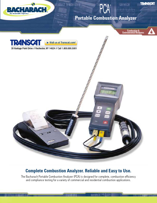
PCA®Portable Combustion AnalyzerComplete Combustion Analyzer. Reliable and Easy to Use.The Bacharach Portable Combustion Analyzer (PCA) is designed for complete, combustion efficiency and compliance testing for a variety of commercial and residential combustion applications.Combustion &Environmental AnalyzersThe PCA is the perfect tool for service technicians and boiler contractors who need to determine carbon monoxide (CO) safety, combustion efficiency and emission testing in combustion applications. The PCA directly measures and displays flue gas O2, temperatures, draft, differential pressure, NO(X)and CO. Simultaneously, the instrument calculates and displays combustion efficiency, excess air, CO2, NO(X)-Ref.O2and CO air free. The large display shows eight different values simultaneously with backlight. The PCA provides seven (7) fuels:natural gas, oil 2, oil 4, oil 6, kerosene, liquid propane and coal, for calculating combustion values. The PCA offers advanced communication features to track and analyze combustion safety tests,efficiency calculations and environmental analysis for residential and commercial applications.The advanced communication features of the PCA 55 and the PCA 65 allow the user to store up to 100 tests, customize each combustion test with customer information, generate a personalized printout, and download all of this information to a personal computer for record keeping and trend analysis.Bacharach Listens To Its CustomersThe most important goal at Bacharach is to meet the needs of you, our customer.We listened to you, and developed the PCA around your needs and requirements.We also contacted several HVAC associations including ACCA, RSES, NAOHSM,and others for their input. As a result, product features were incorporated into the design of the PCA to meet or exceed your expectations. Some of the features include a simple keypad for user friendly operation, an easy to read display showing eight different values simultaneously, an optional infrared printer to document test results and a rugged, lightweight case for added versatility during operation and transport. BACHARACH has developed the PCA to grow with the changing test requirements of the industry. Add-ons and upgraded accessories are constantly reviewed to determinethe value to you, the customer.PCA®Portable Combustion AnalyzerBacharach’s PCA Measures CO Air FreeThe CO air free unit of measurement is computed by the PCA from the CO and O2 measurements. This calculated value determines the amount of CO that would be present in an oxygen free sample by compensating for the amount of excess air provided by the burner. In other words, the CO air free measurement eliminates the excess air dilution caused by primary and secondary air. American National Standards Institute (ANSIZ21) specifies the use of PPM CO air free as a unit of measure when testing certain appliances. The following are the ANSI standards: 200 ppm CO air free on an unvented space heater; 400 ppm CO air free on furnace flue gas; and 800 ppm CO airfree on an unvented gas oven.•Directly measures and displays flue gas O 2,temperatures, differential pressure, Draft, CO and NO (X)•Calculates and displays combustion efficiency, excess air,CO 2, CO air free; and NO (X)- Ref.O 2•Large display shows eight (8) different values simultaneously with backlight•Long life, disposable batteries with an optional 120 VAC power supply •Two year warranty•Draft, CO and NO (X)measurements (optional)•Seven (7) North American fuels•Dated results can be recalled to the display screen at any time•Separate temperature sensor for combustion air •Infra-red serial link for data transfer to printer•Performs local emissions reporting quicker than ever before by selecting the O 2reference between 0 and 15%O 2(PCA 55 & 65 units only)•Stores up to 100 combustion tests for downloading to PC or printer (PCA 55 & 65 units only)Features & BenefitsForced Air Furnaces; Commercial Boilers; Hot Water Heaters; Gas Ovens/StovesSPECIFICATIONSMeasurement Ranges Oxygen0 to 20.9% auto calibration Primary/Ambient Temperature 0°F to 999°F (-18˚ to 999˚C)Stack Temperature 0°F to 2,192°F (-18˚ to 1,200˚C)Carbon Monoxide (optional)0 to 4,000PPM (hydrogen compensated)Draft (optional)-28.0 to +28.0 in. WC (or user selectable inPascal or Millibar)NO (X)(optional)0 to 1,000PPMCalculated Ranges Combustion Efficiency 0.1 to 99.9% (0.1% resolution)Excess Air 1 to 250%Carbon Dioxide 0.1 to a fuel dependent maximum value in percentCarbon Monoxide (air free)0 to 9,999PPM (comes with CO measurement)NO (X)(Ref. 0 to 15% O 2)0 to 9,999PPM Accuracy Oxygen ±0.3% Oxygen (on flue gas)Carbon Monoxide ±5% of reading or±10 ppm, whichever is greater between 0 to 2,000 ppmNO (X)±5% of reading or±5 ppm, whichever is greaterDraft/Differential Pressure ±2% of reading or ±0.02 inches of H 20whichever is greaterStack Temperature±4°F between 32 to 255°F (±2˚C between 0 to 124˚C)±6°F between 256 to 480°F (±3˚C between 125 to 249˚C)±8°F between 481°and 752°F (±4˚C between 250 to 400˚C)Primary/Ambient Temperature ±2˚F between 32 to 212˚ (±1˚C between 0 to 100˚C)Size 8.5 in. H x 3.8 in. W(at display) x 2 in. D (215mm x 96mm x 50mm)Weight Approximately 1.5 lbs. (0.68Kg) with batteries Power SourcePower by four disposable AA size alkaline batteries; minimum of 8 hours of continuous operation. An optional 120 power supply is available for line operationDisplay A 20 character by 4 line alpha numeric display with backlightWarm Up TimeA 60 second total warm up – sensors are checked and autozeroed at warm upInstrument comes complete with: carrying case, probe and hose assembly, factory calibrated and installed sensor(s), instruction manual, user guide, batteries (packaged separately) and a two-year warranty. All instruments can be upgraded to include CO, Draft or NO(X)and other option combinations are available on request.s- Standard with instrument。
ALM-Ⅱ 双通道空燃比分析仪说明书
RS232 串行或者 USB (通过转换器) 友好界面的 PC 机软件以及数据录制和分析工具
显示
LCD 液晶屏
科技创造健康生活
主处理器
CPU 频率 存储器
Freescale MC9S12P128 16-bit 32MHz 96k Flash, 6k Ram, 4k Data
特殊功能
错误自诊断功能 传感器误差及老化自学习功能 特殊燃料兼容
4.1 接插件管脚说明................................................................................................................9 4.2 设备连接............................................................................................................................9 第五章 软件使用说明..................................................................................................................... 11 5.1 安装软件..........................................................................................................................11 5.2 软件操作..........................................................................................................................13
空燃比测试仪美国InnovateLM-2使用说明

LM-2美国Innovate数字空燃比检测仪空燃比检测仪产品使用介绍说明广州智维科技有限公司警告此设备使用的氧传感器在工作时会变得非常热。
请勿触摸这个热的传感器。
不要让热传感器接触可燃表面的。
不要让传感器置于或靠近可燃液体或气体。
未能听取这些警告可能会导致严重烧伤、爆炸或火灾。
当安装在排气中时, 氧传感器必须是与LM-2连接和每次车运行时与LM-2一起工作。
若暴露在热废气,氧传感器将很快损坏。
注意:本手册假定该 1.10 或更高版本的微控制程序已经安装在您的LM-2上。
空燃比测试仪使目录LM-2概述:............................................................................................... 错误!未定义书签。
主菜单 .................................................................................................... 错误!未定义书签。
状态栏的显示 ........................................................................................ 错误!未定义书签。
如何设置菜单屏幕 ................................................................................ 错误!未定义书签。
如何记录 ................................................................................................ 错误!未定义书签。
如何回放 ................................................................................................ 错误!未定义书签。
气体分析仪说明书

BL1020气体连续监测系统技术说明书南京利贝科技有限公司2010年11月亲爱的用户:请在开始工作前阅读此手册!本手册包含重要的信息与数据,遵守它们,是正确使用分析仪器的保证,并且节省维护的费用。
在您使用仪器时,这些信息将会给您很好的帮助,使您获得正确可信的结果。
注意:我们建议你与专家一起讨论您的应用,尤其是在新的应用的时候,比如在研发阶段。
一、系统说明1.1概述本手册描述的仪器在完好的检测后安全的离开工厂。
为了正确使用和操作请按厂家提供的说明书使用。
并且小心遵守操作维护手册以保证安全和正确的运输,储存和安装。
本手册包括本产品的使用证书。
操作技术人员在培训后必须具备适当的仪表和控制的相关知识。
本手册提供的安全知识和相关警告必须正确的注意。
本手册还包括相关运输知识。
如手册中有任何没有包括在内的关于安装操作、维护和使用知识,请与本公司联系。
1.2本手册使用注意事项本手册描述设备的应用情况,及启动,维护,操作的方法。
尤其值得注意的是警告的信息部分,其它的部分分别在别的章节。
1.3危险信息安全信息和警告信号是提示操作人员注意自身及设备不受到伤害或损害。
以下图示代表的意思分别为:危险期意味着如果安全提示没有被注意,将会造成服务人员的伤害或死亡。
警告期意味着如果安全提示没有被注意,将会造成服务人员的伤害或死亡。
注意期意味着如果安全提示没有被注意,将会造成服务人员的伤害或死亡。
提示为产品的重要信息,在操作仪器或阅读本手册时尤其注意。
1.4使用证书允许使用的意思是只在本手册技术部分(第三章)所说明的被Guardian公司所允许的使用范围。
手册中所描述的产品是由生产商所生产、测试过的合格产品。
在正确的使用下不会存在危险。
警告:以下所描述的移动,打开机壳等,可能会有危险的电压存在,所以必须由合格的操作人员对设备进行操作。
1.5合格的操作人员非合格人员操作时可能会使设备发生危险或不能正常使用,所以必须配备合格的人员。
SIM-LAMBDA空燃比分析仪描述

SIM-LAMBDA空燃比分析仪描述SIM-LAMBDA空燃比分析仪的特点●二路或四路模拟输入用于Lambda氧传感器●可测试λ值,空燃比(A/F),氧含量以及电流●包含线性调节的电源器用于传感器加热●直接连接Bosch的传感器●根据要求支持其他传感器●经由软件支持测量配置●测量数据输出到CAN●全面的电隔离(测量输入,也包括CAN)●有移动版本用于汽车测试项目(SIM-LAMBDA)●也有非移动测试台架版本(T-LAMBDA)1.0 硬件和线缆1.1外壳和插槽1.2系统缆线(CAN总线和电源)如果需要我们可以提供更长的电缆!1.3输入电路1.4输入缆线600-672.xxx我们提供所有不同长度不同插头的电缆。
2.0测量五步骤2.1要求除了测量硬件之外我们还需要:●带CAN接口的笔记本(例如Softing CANcard, Kvaser LAPcan)或者带CAN接口的计算机(例如Kvaser leaf professional)我们必须正确安装CAN接口,如果需要可以熟读各个厂商的手册来了解所需的步骤:●Windows软件IPEconf通过CAN总线来配置各模块●作为独立的软件或者作为数据采集软件的选项或者驱动程序(例如DIAdem、INCA、LabVIEW、X-analyser)●如果你的电脑还没安装IPEconf,请把IPETRONIK CD放进光驱安装。
安装之后,自动开启功能会弹出一个语言选择的对话框。
接下来各个软件安装组件的选择菜单会出现。
按设置环境说明书来选择IPEconf的设置。
●该步骤描述连接IPETRONIK驱动的集成IPEconf测试软件的不正确应用(例如DIAdem, INCA)!2.2初始测试步骤一:模块的连接和加电连接一个或多个模块到笔记本或者一台测试计算机,再正确地连接模块到电源供应端,按1.2所描述的操作。
缆线的类型和长度可以随着不同的应用而改变。
接着接通电源。
接通电源之后,模块就立即开始测量。
Sauermann 分析器的燃烧分析仪说明书

sauermann.itGli analizzatori di combustione Sauermann sono dotati delle più recenti tecnologie digitali e metrologiche rendendo le misure più affidabili e riducendo il tempo delle verifiche in opera. Un’esperienza come nessun altro!La proposta di Sauermann intuitiva e compattaper ottimizzare le vostre performance.I nostri analizzatori di combustione sono ideali per le operazioni di verifica e di manutenzione di tutti i generatori a combustione in applicazioni residenziali, commerciali e industriali.• Caldaie • Bruciatori • Scaldaacqua• Motori a gas e diesel• Fornaci• Forni industriali• Impianti di riscaldamento industriali • InceneritoriApplicazioniResidenzialeCommerciale IndustrialeSi-CA 030Si-CA 130Spegnimento automatico dellapompa per livelli di CO elevati(regolabile)Avviso sulla stima di durata delsensore e per il promemoriadi calibrazioneMisure di tiraggioe pressione differenzialeApp per telefoni cellulari pervisualizzazione e controlloremoti in tempo realeCalcolo delRendimento di Combustione,Eccesso Aria, & CO2%Gestione dei dati con registrazioneautomatica e creazione di reportSi-CA 230Si-CA 030Tutto l’essenziale per l’analisi di combustioneSpegnimentoautomatico della pompa per livelli di CO elevatiFino a tre sensori gas. Pu includere O 2, CO, e NO (per calcolo NOx)Il Si-CA 030 offre ai tecnici del riscaldamento tutto ciò di cui hanno bisogno per ispezionare e manutenere caldaie residenziali e commerciali, con connessione wireless alla nostra app per smartphone e generazione automatica di rapporti e certificati.• Predisposto per misura NOx• Controllo rapido e semplice di start/stop della pompa • Monitoraggio del CO ambiente4Analizzatore completo e versatile con schermo touch-screencombustione. Le tre celle e sensori sostituibili sul campo offrono 19.4 c m - 7.5’’DIMENSIONE EFFETTIVASCHERMO TOUCH- SCREENFino ad un massimo di sei sensori di gas e una capacità di misura ampliata, il Si-CA 230 è particolarmente adatto per caldaie, bruciatori, motori ad uso industriale. E con il supporto per più gas e un’elevata soglia di tolleranza alla CO, la sua versatilità lo rende la scelta ideale per applicazioni commerciali e industriali.Fino a sei sensori gas tra O 2,CO, NO, Low NO, NO 2, Low NO 2, SO 2, Low SO 2, H 2S, e CxHy Sensori precalibrati sostituibili sul postoAdeguamento automatico del campo di diluizione CO con misurazioni fino a 50.000 ppm Compatibile con NOx totali e Basso NOx• Ergonomico, Leggero e Resistente• Gestione dei dati con registrazione automatica e creazione di report• Avviso sulla stima di durata del sensore e per il promemoria di calibrazione • Pompa One Touch On / Off con rinfresco• Software per PC Windows con connettivit wireless e USB • Spegnimento automatico della pompa per livelli di CO elevati • Visualizzazione grafica dei dati• Schermata per analisi del gas personalizzabile • Velocit dei fumi con Tubo di Pitot• Misure di tiraggio e pressione differenziale • Valori di emissioni compensati al riferimento O 2• Monitoraggio del CO ambiente • Custodia protettiva in gomma• Sono disponibili contratti di manutenzione ed estensione di garanziaCaratteristiche: Si-CA 230SCREEN7App MobileSauermann Combustion• App gratuite per dispositivi mobile iOS e Android • Software per PC con connettivit USB e wireless • Connessione wireless facile e veloce• Visualizzazione remota in tempo reale dei dati dell’analisi di combustione sotto forma di elenco o grafico• Comando a distanza per modificare le impostazioni • Salvataggio dei dati, inclusa la registrazione automatica • Creazione di report nei formati PDF , CSV (per Excel) e XML • Database per clienti, operatori e apparecchiatureL’app Sauermann Combustion consente di controllare da remotol’analizzatore Si-CA, visualizzare i risultati delle misure in tempo reale e personalizzarli prima di esportarli nel formato che preferisci.DownloadSauermann Combustion appGuida alla selezioneInformazione tecnicaSi-CA 030Si-CA 130Si-CA 230Elementi essenzialidella combustioneThe extra tools you needGli strumenti portatili CO 50 e CO 110 rendono facile misurare leconcentrazioni di CO nell’aria ambiente, così come la temperatura. Ilmodello CO 110 è dotato di sonda a filo, due allarmi regolabili e un ampiodisplay LCD retroilluminato.Misuratore di COCO 50/110Certificato dicalibrazioneFunzione di attesaIl rilevatore di fughe di gas Si-CD3 è perfetto per rilevare in modo rapidoe semplice anche le minime dispersioni di vari gas combustibili (metano,propano, isobutano, GPL e altri idrocarburi).Rilevatore di fughe di gasSi-CD3Allarme regolabileSchermo LCD conretroilluminazione regolabileSonda flessibileda 30 cmDurata della batteria:20 ore (4 batterie tipo AAA)AccessoriPersonalizzare il proprio analizzatoreI nostri analizzatori di gas di combustione sono disponibili in molte configurazioni diverse, con un’ampia gamma di accessori tra cui scegliere. Contatta il nostro servizio clienti per ulteriori informazioni in merito alla scelta sulla migliore configurazione persoddisfare ogni esigenza.S i -C A030S i -C A130S i -C A230ServiziLaboratori metrologici esperti al tuo servizio1101/2022 D o c u m e n t oVisualizza il catalogo onlineUlteriori informazioni sauermann.itCasi studio, informazioni utili e consigli pratici per i professionisti dell’HVACR e della qualità dell’aria。
- 1、下载文档前请自行甄别文档内容的完整性,平台不提供额外的编辑、内容补充、找答案等附加服务。
- 2、"仅部分预览"的文档,不可在线预览部分如存在完整性等问题,可反馈申请退款(可完整预览的文档不适用该条件!)。
- 3、如文档侵犯您的权益,请联系客服反馈,我们会尽快为您处理(人工客服工作时间:9:00-18:30)。
RS232 串行或者 USB (通过转换器) 友好界面的 PC 机软件以及数据录制和分析工具
显示
LCD 液晶屏
科技创造健康生活
主处理器
CPU 频率 存储器
Freescale MC9S12P128 16-bit 32MHz 96k Flash, 6k Ram, 4k Data
特殊功能
错误自诊断功能 传感器误差及老化自学习功能 特殊燃料兼容
科技创造健康生活
第一章 产品概述
ALM(Accurate Lambda Meter)是用来测试空燃比的分析仪器,用来测量尾气中的氧浓度。
ALM 空燃比分析仪(高级双通道)是我公司研发的高档版本空燃比分析仪。使用 2 个 LSU 4.9 氧传感器,由 Bosch 公司的 CJ125 芯片驱动。此产品经常被用于 V 型双缸发动机, 如 V 型 6 缸、V 型 8 缸或 10 缸发动机,具有我公司标准空燃比分析仪的所有优点。并且此 产品将标准空燃比分析仪的 LED 显示方式更换为 LCD 液晶显示器,可以显示更多信息,如 空燃比,氧浓度,过量空气系数,模拟输入等。
更多注意事项
宽域氧传感器不适合在含铅汽油中使用,含铅的汽油会缩短宽域氧传感器的使用寿命。 当宽域氧传感器已经安装在排气管道上,在发动机运转时,请使 ALM 分析仪处于工作 状态,以便控制宽域氧传感器的加热。否则,在传感器未加热的情况下长时间运转发动 机会造成氧传感器损坏。 宽域氧传感器的适宜工作温度范围是 500~900℃,最佳工作温度是 750℃,温度太高 (>1030℃)会损坏传感器,请参考 Bosch LSU4.9 数据手册获得更多关于温度范围变化 的细节。 www.bosch-motorsport.de/pdf/sensors/lambda/LSU49.pdf 避免在发动机启动的时候加热氧传感器,因为在发动机刚起动的时候,尾气中可能会有 雾滴,这样会造成传感器损坏,建议最佳操作顺序:先起动发动机,稍后打开 ALM 分 析仪,这样会顺利促进氧传感器加热的过程。
科技创造健康生活
第四章 ALM 分析仪连接
4.1 接插件管脚说明
接插件功能 引脚序号 接线序号 引脚功能定义
引脚功能说明
1
细黑
GND-R
系统参考地
POWER
2
红色
+12V
+12V 电源
3
粗黑
GND-H
加热地线
1
黄色
VINI1
模拟输入 1
2
深蓝
NBOUT1
窄域氧传感器模拟输出 1
3
紫色
RPM
转速信号输入
常规参数
工作环境温度 产品尺寸
30°C ~125°C 154mm X 163mm X 82mm
科技创造健康生活
第三章 氧传感器安装
正确的安装方式可以有效保护氧传感器,避免水汽凝结成的雾滴损坏传感器的内部结 构,延长使用寿命,同时可以让测量更加准确。传感器应该垂直于排气管道并且相对于水平 线倾斜 10°~75°(参考下图),最佳安装角度为 30°,传感器的头部应该靠近排气管道中 心。
配件列表: 高档空燃比分析仪 线束(标准为 1.5 米,可选 3 米) 2 个 Bosch 原装 LSU4.9 氧传感器 2 套安装用螺栓 串口通讯线 专用 USB 转串口设备(选配) 光盘(内含使用说明以及配套软件
科技创造健康生活
第二章 主要性能参数
电源供电
工作电压 工作电流 极性保护 瞬时电压
I/O
4
浅绿
ANOUT2
线性模拟输出 2
5
深绿
ANOUT1
线性模拟输出 1
6
橙色
VIN2
模拟输入 2
7
浅蓝
NBOUT2
窄域氧传感器模拟输出 2
1
6
IP1
2
5
VM1
O2#1
3
16
4
12
VS1 UN1
接 LSU4.9
5
3
IA1
6
8
RH1
1
11
IP2
2
10
VM2
O2#2
3
1
4
7
VS2 UN2
接 LSU4.9
DC 9V~15V (12V 典型值) 典型工作电流 50mA,另外需要氧传感器加热电流 正负极极性反接保护 最大瞬时电压 33V
传感器
兼容性 传感器数量 自然空气校准
LSU4.9 (LSU 4.2 可选) 两个氧传感器 不需要
测量
测量范围 测量精度
空燃比 氧浓度百分比 响应时间
λ = 0.65 ~ ∞ ±0.008 @ λ=1.00 ±0.01 @ λ=0.80 ±0.05 @ λ=1.70 根据燃料而定(参考 Lambda 范围和精度) 对稀薄燃烧以及气体燃料发动机非常关键 5ms 采样频率
4.1 接插件管脚说明................................................................................................................9 4.2 设备连接............................................................................................................................9 第五章 软件使用说明..................................................................................................................... 11 5.1 安装软件..........................................................................................................................11 5.2 软件操作..........................................................................................................................13
所有的接插件升级到工业级别,铝金属外壳,坚固耐用。现在对尾气中氧气浓度的实时 测量已经成为宽域控制器的新标准,目前只有少数的宽域控制器可以做到。
同时,此款空燃比分析仪可以测量更宽范围的空燃比,尤其在 1.5~3.0,对于某些特殊 燃料发动机来说是必需的,如柴油、气体燃料、弹性燃料、双燃料发动机。目前只有少数的 空燃比分析仪可以做到这些。
在排气管道上找到合适的位置以后,钻出一个直径 18mm 的孔,将传感器固定螺母焊 接固定在上面。 注意:氧传感器和螺母不能同时焊接!
如果用户车辆排气管上有一个 Bosch 的窄域氧传感器,可以卸掉这个窄域氧传感器,将 宽域氧传感器安装进窄域氧传感器的螺母中,Bosch 的宽域和窄域氧传感器具有同样的安装 螺纹。
加热
控制 电流 加热线
使用 CJ125 芯片配合 PID 控制 典型值 1.7A,最大值 3.5A 独立加热线
输出
λ线性输出 模拟输出精度 模拟信号类型
0~5V 用户可设定 ±0.005V 参考地到 ECU
输入
转速输入 其他GT(尾气温度)传感器
通信方式
5
13
IA2
6
9
RH2
注意:LSU4.9 和 LSU4.2 的管脚序号不同,但是对应传感器的导线的颜色相同。
4.2 设备连接
ALM-II 空燃比分析仪
Accurate Lambda Meter
使 用 说 明 书
科技创造健康生活
产品相关图片: 图一 ALM 套件
图二 ALM 分析仪(前视图) 科技创造健康生活
图三 ALM 分析仪(后视图)
目录
第一章 产品概述............................................................................................................................... 5 第二章 主要性能参数....................................................................................................................... 6 第三章 氧传感器安装....................................................................................................................... 8 第四章 ALM 分析仪连接.................................................................................................................9
5.2.1 连接设置...................................................................................................................... 14 5.2.2 数据的录制和回放...................................................................................................... 15 5.2.3 显示控制...................................................................................................................... 17 5.2.4 使用燃料选择.............................................................................................................. 18 5.2.5 故障诊断显示.............................................................................................................. 18 5.2.6 线性输出控制.............................................................................................................. 19 5.2.7 数据显示...................................................................................................................... 20 第六章 常见错误与故障排除.........................................................................................................21 第七章 附录 A: LSU4.9 vs LSU4.2..................................................................................................1