ST04-M(汽车座椅智能温控系统)说明书
智能温控表使用说明书

KKAI208C02A-A/0-201611234:(48*48)6:(96*48)7:(72*72)8:(48*96)9:(96*96)80:(80*160)16:(160*80)484872969616080A 型号H(Min)GBCDEF J 48967248968016097.597.597.597.597.596966.5999913139188.588.588.588.5838345.54567.59292155.5762525252525303045.59267.5459276155.54589.56744.591.575.5155K (Min)25252525253030面板尺寸 侧面尺寸 开孔尺寸J-0+0.5AI208系列E:版本10:单路输入B:一路报警输出 C: 两路报警 A: 无报警功能4: 48W*48H*100L 6:48W*96H*100L 7:72W*72H*100L 8:96W*48H*100L 9:96W*96H*100L AI208系列温控表R:继电器输出 S: 固态继电器输出 K:可控硅输出(需订做)序号型号主控方式2121报警路数1234SSR SSR RELAY RELAYAI208-4/6/7/8/9-SC10AI208-4/6/7/8/9-SB10AI208-4/6/7/8/9-RC10AI208-4/6/7/8/9-RB10智能温控表使用说明书本说明书对温控表设置、配线及各部分名称等进行说明,使用本产品前,请认真阅读本说明书,在理解内容的基础上正确使用。
并请妥善保存,以便需要时参考。
⊙支持多种热电偶、热电阻信号类型⊙采用模糊PID 控制算法,且自整定无过冲⊙多种控制方式可选,具体请参照OT 参数⊙RUN/STOP,运行/停止功能一键切换特点2、隔离模式框图:固态继电器输出绝缘电阻静电放电脉冲群抗扰度浪涌抗扰度电压暂降及短时中断抗扰度隔离耐压DC 24V 脉冲电平,带载<30mA 输入、输出、电源对机壳>20MΩIEC/EN61000-4-2 Contact ±4KV /Air ±8KV perf.Criteria B IEC/EN61000-4-4 ±2KV perf.Criteria B IEC/EN61000-4-5 ±2KV perf.Criteria BIEC/EN61000-4-29 0%~70% perf.Criteria B信号输入与输出及电源1500VAC 1min,60V 以下低压电路之间DC500V,1min 整机重量约 400g机壳材质面贴材质停电数据保护面板防护等级安全标准外壳与面板基架PC/ABS (难燃度UL94V-0)PET(F150/F200)10年,可写数据次数100万次IP65(IEC60529)IEC61010-1 过电压分类Ⅱ,污染等级2,等级Ⅱ(加强绝缘)3、测量信号参数表:1、电气参数表:采样速度2次每秒供电电源继电器容量AC 250V /3A 额定负载寿命大于10万次AC/DC 100~240V (85-265V)三、主要技术参数二、常规型号说明一、仪表型号周围环境条件整机功耗存贮环境< 6VA室内使用,温度:0~50℃ 无结露,湿度:<85%RH,海拔小于2000m -10~60℃,无结露□:外形尺寸可选注意:选择加热冷却控制方式时,如还需报警功能,请选择带两路报警的型号。
智能温度控制仪使用说明书.
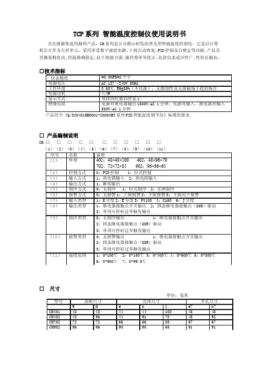
TCP系列 智能温度控制仪使用说明书首先感谢你选用赫明产品,CH系列是公司潜心研发的普及型智能温度控制仪。
它是以计算机芯片作为主控单元,采用多重数字滤波电路、干扰自动恢复、PID控制及自整定等功能。
产品具有测量精度高、控温准确稳定、抗干扰能力强、操作简单等优点、此款仪表适应性广、性价比极高。
产品符合《Q/320401HBD001-2000XMT系列PID智能温度调节仪》标准的要求□ 产品编制说明CH □ □ □ □ □ □ □ □ □ □ □(1)(2)(3)(4)(5)(6)(7)(8)(9)(10)(11)□ 尺寸单位:毫米□ 面板各部分说明1、设定键2、左移键3、设定值加键4、设定值减键5、设定值窗口6、采样值窗口7、输出指示灯 8、报警1指示灯 9、报警2指示灯□操作1、在PID参数设定方式,每按一次(SET)键,将按顺序显示下表参数,但是根据订货规格,有些参数可能不出现,初始值也可能有所不同。
2、如需位式控制,请修改下列参数为Pv=0 Dv=下回差值,SPv=0(无需回差值,则Dv=0)2、自整定的准确使用控温精度对仪表而言关键是PID的参数要选择合理,但由于各种加热对象差异很大,PID参数也相差甚大,对非专业人士,可以通过自整定来达到较为理想的控温较果。
在参数自整定之前,先确定该控制系统是否允许在位式控制状态下(控制量是0%或100%)工作,若不允许,PID参数就须采用手工设置。
本仪表自整定的专家经验公式是根据自整定启动后的两次过冲幅值及自整定过程所用的时间经过运算后得出来的,因此启动自整定时测量值越是小于设定值,则自整定的效果越理想。
自整定过种中不要有异常的扰动(如负载的变化,打开箱门)和修改相关的参数(如测量值)的情况。
自整定给出的参数在某些情况下可能并不是最佳的,因此用户在某些使用过程中还须在此基础上进一步修改。
3、PID参数的手工整定当系统因环境温度变化很多或系统本身的差别造成系统控温达不到使用要求时,可依以下几种情况对PID参数进行调节,以达到使用要求:a)当系统在比例带范围内加热很少而又要冲温时,应增大比例带P。
智能温控仪表XMT-808使用手册

姚仪® CMC浙制02810232XMT* 808系列 智能温度控制仪表 使用说明书(万能输入)余姚市长江温度仪表厂余姚市工易仪表有限公司万能输入版本2007姚仪R余姚市工易仪表有限公司目 录目 录 (1)安全注意标志 (3)第一章 概述 (3)第二章 技术指标 (4)2.1输入规格 (4)2.2测量精度 (4)2.3响应时间 (4)2.4调节方式 (4)2.5输出规格 (4)2.6通 讯 (4)2.7报警功能 (4)2.8隔离耐压 (4)2.9手动功能 (4)2.10电源供电 (4)2.11工作条件 (5)2.12产品认证 (5)第三章 产品选型 (5)3.1型号意义 (5)第四章 安装与接线 (5)4.1 XMT-808接线图 (6)4.2 XMTD-808接线图 (6)4.3 XMTA/E/F-808接线图 (7)4.4 XMTG-808接线图 (7)4.5 可控硅触发接线图 (8)第五章仪表面板说明 (8)5.1仪表面板图 (8)5.2面板说明 (8)第六章基本设置及操作 (9)6.1温度给定值设置 (9)6.2参数设置 (9)6.3手动/自切换 (9)6.4自整定操作 (9)6.5手动自整定 (10)姚仪R 余姚市长江温度仪表厂2地址:浙江省余姚市工业开发区西区第七章 功能及设置 (10)7.1操作流程图 (10)7.2参数功能说明 (11)第八章 部分功能的补充说明 (16)8.1线性电流输出 (16)8.2时间比例控制 (16)8.3远传压力控制 (17)8.4热电偶冷端补偿 (17)第九章 仪表常用控制方式 (18)9.1二位式调节/仪表报警 (18)9.1.1二位式调节介绍 (18)9.1.2二位式调节举例 (18)9.2温度变送 (18)9.2.1温度变送介绍 (18)9.2.2温度变送举例 (18)9.3通讯功能 (18)9.3.1通讯功能介绍 (18)9.3.2通讯功能接线 (19)第十章 故障分析及排除…………………………………………………………………… ―20― 附1:仪表参数提示符字母与英文字母对照表………………………………………… ―20― 第十一章 产品服务指南……………………………………………………………………―21―姚仪R余姚市工易仪表有限公司安全注意标志在阅读说明书时会出现以下标志,分别表示“危险”、“注意”。
奇瑞四季全速座椅说明书

A FEW WORDS ABOUT PRODUCT SAFETY:Your Quadratec Jeep product is intended to enhance the utility and enjoyment of your off-road capable vehicle. Follow safety information and installation recommendations. Throughout these instructions is important safety information that is generally preceded by one of three signal words indicating the relative risk of injury, property damage or adverse consequence. The signal words mean: A HAZARDOUS SITUATION WHICH, IF NOT AVOIDED, COULD RESULT IN DEATH OR SERIOUS INJURY. YOU CAN BE KILLED OR SERIOUSLY HURT IF YOU DON'T FOLLOW INSTRUCTIONS .CAREFUL ATTENTION IS REQUIRED TO THIS INSTRUCTION OR OPERATION BUT DOES GENERALLY NOT RELATE TO PERSONAL INJURY. DAMAGE TO YOUR QUADRATEC ® PRODUCT OR OTHER PROPERTY MAY RESULT IF YOU DON'T FOLLOW INSTRUCTIONS.A HAZARDOUS SITUATION WHICH, IF NOT AVOIDED, COULD RESULT IN A MINOR OR MODERATE INJURY. YOU CAN BE MODERATELY HURT AND ALSO MAY SUFFER PROPERTY DAMAGE IF YOU DON'T FOLLOW INSTRUCTIONS.BEFORE YOU BEGIN INSTALLATION:Congratulations on your purchase of Quadratec ® Seats for your Jeep ® Wrangler. When unpacking, check to make sure all parts are included and not damaged due to shipping. If any part is missing or broken, please call Customer Service at 800-745-6037 as soon as possible. Thank you again for your purchase and let’s start the installation process.READ ALL SAFETY MESSAGES AND ALWAYS WEAR SAFETY GLASSES WHEN WORKING WITH TOOLS. TO REDUCE RISK OF SERIOUS INJURY OR PROPERTY DAMAGE: READ ALL SAFETY MESSAGES AND UNDERSTAND ALL INSTRUCTIONS AND PROCEDURE NOTICES BEFORE ATTEMPTING TO INSTALL OR USE THIS PRODUCT.RISK OF EYE INJURY! SAFETY GLASSES MUST BE WORN AT ALL TIMES WHILE INSTALLING OR MAINTAINING THIS PRODUCT. TORQUE AND RECHECK FASTENERS AFTER 250 MILES AND FREQUENTLY THEREAFTER. DO NOT USE IF DAMAGED.M8 x 25 (x4)KIT CONTENT LIST:A. Seat Back B. Seat Base C. M8 x 25 Bolt (4)REQUIRED TOOLS: Safety Glasses 13mm Socket or WrenchWith seat base on its side, locate the long plastic trim clip. Pull downward to release the clip from the lower frame (Fig 1). This will release the trim to access bolt hole locations for seat back brack-et (Fig 2). Repeat process on other side.FIG 1BEFORE PROCEEDING WITH INSTALLATION, YOU MUST REMOVE THE EXISTING SEAT. SAVE THE BOLTS THAT SECURED THE EXISTING SEAT TO THE VEHICLE. YOU WILL NEED THOSE BOLTS TO ATTACH YOUR NEW SEAT TO THE VEHICLE.Lay seat base flat on work surface (Fig 3). Position seat back to slide brackets into slots in the fabric in the rear of the seat base. This motion will follow the path of the arrow shown (Fig 4).Lift and move the fabric along the bottom of the base away to expose the base and the brackets. Align the holes of the seat back bracket with the bolt holes of the base (Fig 5). Hand thread the two bolts for the first side of the base (Fig 6).STEP 3FIG 3FIG 4FIG 5FIG 6Using a 13mm socket or wrench, tighten bolts to hold bracket (Fig 7). Do not fully tighten at this time.Repeat previous steps for other side.After both sides are attached, tighten each bolt securely.After you removed an old seat from riser, reuse those bolts for reattachment. Inspect all bolts and replace, if missing or damaged, with grade 8 bolts or stronger. One bolt in each corner must be used (4 total) for mounting. The bolt holes in the internal frame of the seat are meant to accomodate multiple sized risers (not included). (Fig 8) Refer to factory service manual for specific torque specifications.STEP 5SEATS MUST BE SECURELY BOLTED AT ALL PRIOR BOLT LOCATIONS.FIG 7FIG 8Your Quadratec® branded accessories are covered by the following Limited Warranty provided exclusively by Quadratec, Inc., 1028 Saunders Lane, West Chester PA 19380.This Limited Warranty is the only warranty made in connection with your purchase. Quadratec neither assumes nor authorizes any vendor, retailer or other person or entity to assume for it any other obligation or liability in connection with this product or Limited Warranty. This Limited Warranty does not apply and is not cumulative to any accessory or part distributed by Quadratec for which the Manufacturer provides a separate written warranty.What is Covered:Subject to the terms, exclusions and limitations herein and with respect only to Quadratec branded accessories first sold in the United States, Quadratec warrants to the initial retail purchaser only that your Quadratec accessory shall be free of defects in material and workmanship: for a period of three (3) years from date of retail purchase.This Limited Warranty is not assignable and shall terminate upon sale of the vehicle upon which the Quadratec accessory is installed or other transfer to third persons.All other warranties are hereby disclaimed, except to the extent prohibited by applicable law in which case any implied warranty of merchantability or fitness for a particular purpose on this product is limited to 3 years from date of initial retail sale. Quadratec reserves the rights to: (a.) require invoice or other proof your accessory is within the terms of this Limited Warranty as a condition of warranty service and, (b.) make future revisions to this product and Limited Warranty without prior notice or obligation to upgrade your product.What is Not Covered:Your Quadratec Limited Warranty does not cover products or parts Quadratec determines to have been damaged by or subjected to: (a.) installation damage, alteration, modification, combination with other parts, failure to maintain or improper repair or service, (b.) normal wear & tear, cosmetic damage or damage from moisture or water immersion, (c.) Acts of God, accidents, misuse, negligence, inadequate mounting or impact with vehicle(s), obstacles or other aspects of the environment, (d.) theft, vandalism or other intentional damage.Remedy Limited to Repair/Replacement:The exclusive remedy provided hereunder shall, upon Quadratec inspection and at option, be either repair or replacement of product or parts (new or refurbished) covered under this Limited Warranty. Customers requesting warranty consideration should first contact Quadratec to obtain a RGA number (610-701-3336). All labor, removal, shipping and installation costs are customer’s responsibility.Other Limitations - Exclusion of Damages - Your Rights Under State Law:In consideration of the purchase price paid, neither Quadratec nor any independent Quadratec distributor/licensee are responsible for any time loss, rental costs, or for any incidental, consequential, punitive or other damages you may have or incur in connection with any part or product purchased. Your exclusive remedy hereunder for covered parts is repair/replacement as described above.This Limited Warranty gives you specific rights. You may also have other rights that vary from state to state.For example, some states do not allow limitations of how long an implied warranty lasts and /or do not allow the exclusion or limitation of incidental or consequential damages, so the limitations and exclusions herein may not apply to you.©Quadratec, Inc. 2021. All Rights Reserved.A4 Version 11/17/2021Instructions Part #12999.3214。
Series 40T 40M数字温度开关安装与使用说明说明书

The Series 40T/40M Digital Temperature Switch accepts a variety of inputs to allow temperature measurements and set points up to 1999°F (1300°C). Observing the current status of the control is made easier with the 3-1/2 digit, multi-color LED display that has alarm, defrost and output symbols. For added versatility, the temperature units can be field selected for °F or °C. For cooling applications, manual defrost mode can be initiated by pushing a single button. A flashing alarm informs users when the current temperature exceeds preset limits.INSTALLATIONNote: Unit must be mounted away from vibration, impacts, water and corrosive gases.• Cut hole in panel 71 x 29 mm (2.80 x 1.14 in)• Apply silicone around the perimeter of the hole to prevent leakage • Insert unit into hole from the front side of the panel• Slide the mounting bracket securely against the panel from the rear of the unit • Wiring diagram is displayed on top of the controlADJUSTING PARAMETER VALUESIn order to change the parameter values, follow the procedure below:• Press UP ARROW and DOWN ARROW simultaneously for four seconds until PA is displayed • Press SET• Use UP ARROW or DOWN ARROW to adjust value to -19• Press SET• Press UP ARROW and DOWN ARROW simultaneously for four seconds until SP is displayed• Use UP ARROW or DOWN ARROW to cycle through parameters • Press SET to view value of parameter• Use UP ARROW or DOWN ARROW to adjust value of parameter • Press SET to store value• Press UP ARROW and DOWN ARROW simultaneously for four seconds to exit menuWIRINGAvoid installing the temperature probe cables in close proximity of any power cables. If the length of the probe cables is longer than 100 meters, a recalibration adjustment may be made using the CA1 parameter.ELECTRIC SYSTEMPOWER SUPPLYPTC/NTC PROBES12111091211121110121112IN COM COM IN CP COM COM IN 12 V R O O MR O O MR O O MR O O MJ/KTHERMOCOUPLES2/3 WIRES PT 100,PT 1000 AND NI 120 PROBES 0-20/4-20 mA AND 0-10/2-10 VACTIVE TRANSDUCERS2/3 WIRES 4-20 mAPASSIVE TRANSDUCERSIN 111097654321M A X . 10 AK 1L O ADPARAMETER DESCRIPTIONSP Sets ambient temperature set point between r1 and r2CA1Ambient probe calibration adjustmentP0P1 Position of decimal placeP2 Display engineering units0 °C1 °F2 No unitsP3Minimum value for process inputP4Maximum value for process inputP5Value shown during normal operation0 Probe temperature1 Set pointr0Set point differential or hysteresisr1Minimum value for set pointr2Maximum value for set pointr3 Set point lock out0 Unlocked1 Lockedr5 Selection of heating/cooling operation0 Cooling1 HeatingC1Minimum time between compressor startsC2 Minimum time compressor must remain off before being restartedC3Minimum time compressor must remain on after being startedC4During probe error, time compressor is offC5During probe error, time compressor is ond0Interval of time between defrost cycles (if 0, defrost will never be activated) d3 Duration of defrost cycled4Start defrost cycle upon power up0 No1 Yesd5Defrost delay time upon power up (d4 must be 1)d6 Temperature shown during defrost0 Display probe temperature1 = Display probe temperature up to (set point + r0) if probe temperatureis below (set point + r0) at activation of defrost cycle. Display probetemperature if the probe temperature is above (set point + r0) at activation of defrost cycle.A1Alarm 1 temperature set pointA2Alarm 1 not activated unless temperature remains in alarm state for this timeA3 Alarm 1 type0 Alarm disabled1 Absolute low alarm (A1)2 Absolute high alarm (A1)3 = Deviation low alarm (SP - A1)4 = Deviation high alarm (SP + A1)A4Temperature alarms not activated for this time after modifications to setpointA5Alarm 2 temperature set pointA6Alarm 2 not activated unless temperature remains in alarm state for thistimeA7 Alarm 2 type0 Alarm disabled1 Absolute low alarm (A1)2 Absolute high alarm (A1)3 = Deviation low alarm (SP - A1)4 = Deviation high alarm (SP + A1)E9 ReservedPrinted in U.S.A. 3/21FR# 443741-00 Rev. 6©Copyright 2021 Dwyer Instruments, Inc.DISPLAYING ROOM TEMPERATUREIf the P5 parameter is set to display the temperature set point, the probe temperature can be displayed by pressing the DOWN ARROW key for two seconds until Pb1 is displayed. Next, hit the SET key. To return to the normal display, press SET key.MANUAL DEFROST ACTIVATION/DEACTIVATIONTo manually activate the defrost cycle, press the UP ARROW key for four seconds. This feature is disabled during heating operation.PARAMETER LOCK OUT ACTIVATION/DEACTIVATIONThe key pad lock out can be activated/deactivated by pressing the SET and DOWN ARROW keys simultaneously for two seconds. The display will flash Loc or UnL to signify the change in states.ALARM BUZZER RESETThe audible alarm can be silenced by pressing any key.RESTORING FACTORY DEFAULT SETTINGSFactory settings can be restored by following the below procedure:• Pressing the UP ARROW and DOWN ARROW keys for four seconds until PA is displayed• Press the SET key• Press the UP ARROW or DOWN ARROW to adjust the value to 743• Press SET key• Pressing the UP ARROW and DOWN ARROW keys for four seconds until dEF is displayed• Press SET key• Press the UP ARROW or DOWN ARROW to adjust the value to 149• Press SET key• Cycle the power after the flashing dEF goes awayMAINTENANCE, CLEANING AND REPAIRAfter final installation of the unit no routine maintenance is required. Clean the surface of the display controller with a soft and damp cloth. Never use abrasive detergents, petrol, alcohol or solvents. A periodic check of the system calibration is recommended. The Series 40T/40M is not field serviceable and should be returned if repair is needed (field repair should not be attempted and may void warranty). Be sure to include a brief description of the problem plus any relevant application notes. Contact customer service to receive a return goods authorization number before shipping.°C °F Loc。
智能温度控制器使用说明书

智科电子智能温度控制器使用说明书型号:TK40版本号:V 1.12010.4.6中国.四川德阳智科电子有限公司目录概述设备技术参数操作键说明控制过程说明菜单数码管显示定义维修和保养德阳智科电子一、概述智能温度控制器是为了解决单个风幕机独立工作而开发设计的控制器,是保证集成式加热器能在-35℃—60℃的低温环境下,能安全可靠运行而设计的一个重要附助控制设备。
该控制器最大的优点在于,风幕机的启停温度可以通过人工进行设置,独特的全开放式用户自设定界面,双线联机使用具备各自独立启动,在上电的瞬间,同时联机的几台控制器将通过“抢答”的形式来逐个启动控制器,这是本控制器改进后的亮点。
用户在使用TK40温度智能控制器时请仔细阅读本说明书及集成式加热器系统说明书,并严格按照说明书要求进行操作、检查、安装和维护。
二、设备技术参数1、ZK40温度智能控制器电源:12V 50HZ2、测量范围:-60℃—150℃3、测量精度:±1字4、分辨率:0.1字5、显示方式:测量值显示发光二极管工作状态显示6、使用环境:环境温度:-40℃—80℃工作温度:-35℃—60℃相对湿度:≤85RH7、结构:标准卡入式8、重量:250g三、操作键说明31、温度显示数码管在正常情况下,该4位数码管显示实际检测到的温度数值,此时对应的菜单代码为L002、菜单显示数码管在正常情况下,该3位数码管显示L00,代表意思是:上面4位数码管显示的是温度(以数值形式显示)或则显示“Erro”(故障)3、返回按键(BACK):在参数设后,按下该键,3位菜单数码管将返回到正常状态“L00”;当4位数码管显示“Erro”时,在排除外部所有电气故障时,按下该键将一键清除内部故障锁存,控制器进入正常工作模式。
4、向上按键(UP):在设定参数值时,该键用来增加数值;在进行菜单翻页时,该键用来上翻。
德阳智科电子5、向下按键(DOWN):在设定参数时,该键用来减少数值;在进行菜单翻页时,该键用来下翻。
Sensi 智能恒温器 使用说明书

SENSI TM SMART THERMOSTATManual OperationModels: 1F87U-42WF, ST55Version: January 2020©2020 Emerson Electric Co. All rights reservedR-5029.Table of ContentsIcons 3 andButtonsFunctionality 4 Basic6 SettingsManual8 MenuConfigurationsTerminals 9 WiringPlate10 FaceofBacktheThe Sensi Smart Thermostat can be operated through Wi-Fi using the Sensi app or it can be operated at the actual wall unit. Advanced features such as thermostat settings, scheduling and email alerts are only available through the Sensi app.WI-FI STATUS ICON Indicates Wi-Fi connection status. When you turn Wireless Off on the thermostat, this is blank.BACKLIGHT BUTTONIlluminates the thermostat for 10 secondsTIMEDisplays current time.KEYPAD LOCKOUT ICONThis icon indicates the thermostat is locked out. No changes can be made at the thermostat. (Can only be enabled from the Sensi app).BATTERY ICONWhen the bars get low, remember to change the 2 AA Alkaline batteries in the back of the thermostat face plate.UP ARROW BUTTON Adjusts the temperature set point or thermostat configuration.CURRENT SET TEMPERATURECurrent set temperature the thermostat will maintain.MENU BUTTONAccess thermostat configurations. (See page 6 for more details).DOWN ARROW BUTTONAdjusts the temperature set point or thermostat configuration.CURRENT ROOM TEMPERATUREThe room temperature at the thermostat.SCHEDULE BUTTONToggles the schedule On or Off. (The thermostat runs a program based on time and temperature set points when Schedule is On).FAN BUTTONSwitches fan mode from Auto or On. Leave the fan mode on Auto to allow the thermostat to control the fan as necessary.MODE BUTTONSwitches system mode between Heat, Cool, Off or Aux. (Auto Mode is only available using the Sensi app).Switching System ModePress the “Mode” button to switch between all available system mode settings. When the Mode is “Off” the thermostat will not bring on your heating or cooling systems.Fan ModeIf you want to circulate the indoor blower, you can switch Fan to “On.” Turn theFan back to “Auto” when you want the thermostat to control your indoor bloweras necessary. Leaving the Fan in “On” will run your blower continuously.Holding One TemperatureIf you want to hold one temperature, turn Schedule “Off.” Then, adjust theset point using the up and down arrow buttons. The thermostat will holdthis temperature, in the set Mode, until you turn Schedule back “On” or untilyou adjust the set point again using the up and down arrow buttons.Temporary HoldWhen your schedule is set to “On,” your Sensi thermostat controls your home based on the time and temperature settings in the current schedule. To temporarily change your temperature use the up and down arrows in the app or on the thermostat. Your Sensi thermostat will display “Temporarily Set To” on the thermostat and will hold your new temperature until the next scheduled set point with a minimum hold time of two hours.Circulating FanIf you want to circulate the air in your home using your indoor blower fan, you can set this feature in the app or at the thermostat. A percentage is selected to indicate how often the fan should run each hour, You can set 5% increments from 10% – 100%. EXAMPLE:If you set the Circulating Fan to 50%, the fan will run 30 minutes every hour.If any heat/cool cycles occur during the hour, their runtimeis subtracted from the overall fan run time.Setting the feature from the thermostat:1. Press “Menu”2. Press “Next” until you come to “Fn Setup”.3. Use the up arrow button to toggle the percentage you’d like the fan to run each hour.4. Press “Exit”Turn Wi-Fi OffIf connecting to Wi-Fi is not an option, you can turn off Wi-Fi on the thermostatand manually set a time and a schedule from the wall unit. To turn off Wi-Fi:1. Press “Menu”.2. P ress “Next” until you see “Wireless (Setup)” at the top of the screen.“On” should be flashing at the top.3. Use the up or down arrow button to change it to “Off”.4. Press “Exit”.Setting the Time ManuallyWhen connecting the thermostat to Wi-Fi, the time will sync automatically. If not connecting to Wi-Fi, follow these steps to set the time at the thermostat.1. Turn Wi-Fi Off. (Refer to section “Turn Wi-Fi Off” on page 4).2. Press and hold the “Schedule” button.3. T he screen will go blank and the time will start flashing at the top. Use the up and downarrow buttons to rotate through the times until you get to the appropriate time of day.4. Press “Exit”.Setting a ScheduleWhen connecting the thermostat to Wi-Fi, the schedule isprogrammed based on time and temperature set points from theSensi app. If you are not connecting to Wi-Fi, follow these stepsto set a basic 7 day schedule with 4 mandatory set points.1. Turn Wi-Fi Off. (Refer to section “Turn Wi-Fi Off” on page 4).2. Use the “Mode” button to set which type of schedule it will be: Heat or Cool.3. Press and hold the “Schedule” button, until you see the time flash at the top of the screena. Adjust the time on the thermostat if needed, using the up and down arrow buttons.4. Press “Next”5. You will see a large number in the middle of the screen. This refers to your set point.a. The time will be flashing at the top of the screen. Adjust the time ofthe first set point using the up and down arrow buttons.b. Press “Next”. The set point will be flashing. Adjust the setpoint using the up and down arrow buttons.c. Press “Next”.d. Repeat steps a-c for the second, third and fourth set points.6. Press “Exit”.7. Make sure “Schedule” is set to “On” on the thermostat.Example ScheduleIf you need to keep track of your time and temperature set points, use this table. SAMPLE SCHEDULE1st6:00 am70° F2nd8:00 am62° F Heat3rd5:00 pm70° F4th10:00 pm62° F1st6:00 am78° F2nd8:00 am85° F Cool3rd5:00 pm78° F4th10:00 pm82° F COMPLETE YOUR SCHEDULE1st6:00 am2nd8:00 amHeat3rd5:00 pm4th10:00 pm1st6:00 am2nd8:00 amCool3rd5:00 pm4th10:00 pmPressing “Menu” at the thermostat allows you to change a series of settings to customize the thermostat for your specific system. Refer to the chart below for a complete listing of thermostat configurations and what they stand for. If you are installing the thermostat on the wall for the first time, we highly recommend that you download the Sensi app and follow the installation instructions.However, if you are experiencing an issue or you want to check your system configurations, you can manually configure your thermostat as well. Learn more about how to properly configure your thermostat by searching “configure” on our support site at /en-us/support.Display CodeMenu item Default Options Wireless SetupConnects Thermostat to Wi-Fi network —Connect Fahrenheit or CelsiusFF COutdoor EquipmentConfigurationCooling or heat pumpsAC2AC1 – C onventional Cooling 1 (Single Stage)AC2–C onventional Cooling 2 (Two-Stage)HP1 – H eat Pump 1 (Single Stage)HP2– H eat Pump 2 (Two-Stage)AC0– N o Cooling Indoor Equipment ConfigurationFor Gas or Electric HeatEL2EL1–E lectric 1 (Single Stage)EL2–E lectric 2 (Two-Stage)FAn GA1 Gas 1 (Single Stage)GA2 Gas 2 (Two-Stage)Reversing Valve Position Selects “O” or “B” Setting For Heat Pumps OnlyO O B2Fn Circulating Fan OFF Off/10% – 100% (5% increments)H AA Humidification Add Accessory OFF Off/OnH SPHumidification Set Point OFFOff/5% – 50% (5% increments)dH AA Dehumidification Add AccessoryOd Od/OcOd – Optimal dehumidification(Overcool to dehumidify)Oc – Optimal comfort (Wired dehumidification)dH SPDehumidification Set PointOFF Off/40% – 95% (5% increments)Wireless RadioTurns Wi-Fi Radio On/OffONOff/OnSee below for definitions of the wiring terminals on the sub-base of the thermostat. Terminal outputs and wiring diagrams* If the old thermostat has separate RC and RH wires coming out of the wall, clip the RC/RH jumper on the back of the thermostat above the battery compartment.**The common wire could be labeled “C” on your old thermostat, or it could be labeled “B”or “X.” Please refer to the owner’s manual of your old thermostat for clarification.Does Wire Color Correspond to the Thermostat Terminals?Wire color does not always correspond to the thermostat letters. A white wire may be attached to the “W” terminal on the old thermostat, or it may be attached to a different terminal with a different letter. Be sure to take a photoof the old thermostat that shows the wire colors and terminal letters before labeling and removing any wires.Below is a picture of the back of the Sensi thermostat face plate. The back plate shows the jumper wires, battery compartment, and some useful information about your thermostat.SENSI SECURITY CODENecessary for connecting to Wi-Fi. Also foundon the Welcome Guide in the packaging.MODEL NUMBERIllustrates whether you purchased theprofessional or the DIY model.APPLE HOMEKIT CODEThe 8 digit code used to add Sensi Thermostat to Apple HomeKit.. RC/RH INTERNAL JUMPER WIREOnly clip this if you have separate RC and RH transformers coming out of the wall.BATTERY COMPARTMENTTwo AA Alkaline batteries are used for back-up purposes. When you see the battery indicator bar on the thermostat display reach 3 bars, replace these batteries to maintain Wi-Fi connectivity. DATE CODEWhen your thermostat was manufactured.MAC IDUnique number that identifies the thermostat.。
汽车座椅手册江森自控

提高客户满意度: 提供详细、准确的 信息,帮助客户更 好地了解和使用产 品
增加销售额:通过 提供全面的产品信 息,吸引更多潜在 客户购买
提升品牌形象:专 业的汽车座椅手册 有助于提升江森自 控公司在行业内的 知名度和声誉
促进售后服务:手 册中的信息有助于 售后服务团队更好 地为客户解决问题 和提供支持
保养知识。
信息全面:涵盖 了汽车座椅的各 个方面,包括产 品介绍、安装指 南、使用说明、 保养提示等,为 读者提供全面的
信息支持。
更新及时:随着 汽车技术的不断 发展和改进,手 册会及时更新以 反映最新的产品 特性和操作要求。
针对不同车型和座椅型号提供详细的安装和使用说明 提供座椅调整和设置的最佳实践指南 针对座椅材料和保养提供专业建议和说明 实用图表和图片辅助说明,易于理解和操作
江森自控公司不断投入研发,致力于技术创新和产品升级,以满足不断变 化的市场需求。
公司注重人才培养和技术引进,通过与高校和研究机构的合作,推动技术 研发和成果转化。
江森自控公司关注行业发展趋势,积极布局新兴领域,如智能座椅、空气 质量监测等,以提升产品竞争力。
公司持续优化生产流程,提高生产Fra bibliotek率和产品质量,以满足客户对高品质 产品的需求。
XX,A CLICK TO UNLIMITED POSSIBILITES
汇报人:XX
目录
CONTENTS
成立时间:1920 年
总部地点:美国 威斯康星州密尔 沃基市
业务范围:汽车 座椅、内饰、安 全系统等汽车零 部件的研发、生 产和销售
全球员工数量: 约2万多人
成立背景:江森自控公司成立于1987年,由江森和自控两个公司合 并而成,旨在提供智能建筑解决方案。
精达仪表智能温度控制仪使用说明书
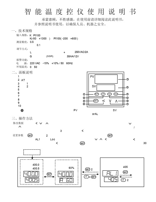
三、操作方法OUTATAL1AL2SETVVVPVSV13245867910修改数据:可通过按、或键来修改。
给定值。
仪表同时具备数据快速增减法和小数点移位法按键减小数据,按键增加数据,可修改数值位的小数点同时闪动(如同光标)。
按键并保持不放,可以快速地增加/减少数值,并且速度会随小数点会右移自动加快(3级 速度)。
而按键则可直接移动修改数据的位置(光标),操作快捷。
设置参数:2秒钟,即进入参数设置状态。
在参数设置状态下按键,仪表将依次显示各参数,例如上限报警值AL1、参数锁Loc 等等,如果参数没有锁上可用、、等键修改参数值。
按键并保持不放,可返回显示上一参数。
先按键不放接着再按键可退出设置参数状态。
如果没有按键操作,约30秒钟后会自动退出设置参数状态。
仪表上电后,仪表上显示窗口显示测量值(PV ),下显示窗口显示给定值(SV )。
输入的测量信号(输入断线或短路均可能引起)时,则闪动显示orAL ,此时仪表将自动停止控制。
调节输出指示灯(1)报警(3)指示灯1报警(4)指示灯2(2)指示灯(本型号未使用)AT 显示转换(兼参数设置进入)(5)数据移位键(6)数据减少键(7)数据增加键(8)给定值显示窗(9)测量值显示窗(10)二、面板说明输入规格:K 、Pt100测量范围:K(-50-+1300)、Pt100(-200-+600)测量精度:0.5级测量显示分辨率:0.1℃调节方式:位式调节或带自整定功能的智能调节输出规格:继电器触点开关输出(常开+常闭),250VAC/2A L 固态继电器G 电压输出,(SSR)30mA/12V (用于驱动固态继电器)报警功能:上限报警电 源:220VAC ,-15%,+10% / 50-60Hz 环境温度:0-50℃智 能 温 度 控 仪 使 用 说 明 书承蒙惠顾,不胜感激,在使用前请详细阅读此说明书,并参照说明书使用,以确保人员、机器之安全。
一、技术规格超出量程四、自整定(AT)操作本系列采用的智能调节算法是应用了模糊规则进行PID 调节的一种新型算法,具有自整定功能并在调节中记忆被控对象的部分特以使效果最优化,无需人为调节参数,使用简便。
ecs-40温控器说明书

ecs-40温控器说明书Ecs-40温控器是一种具有温度控制功能的设备,它能够根据环境的温度变化,自动调节设备的功能,起到保护设备和提高设备使用寿命的作用。
本文将详细介绍Ecs-40温控器的使用方法和注意事项。
一、Ecs-40温控器的使用方法1.连接电源线将Ecs-40温控器的电源线插入电源插座中,使用电源开关控制设备的开关状态。
2.连接控制设备将需要控制的设备连接到Ecs-40温控器上,一般需要连接电源线和温度传感器等,注意正确连接各管脚。
3.设置温度按下设置按钮进入温度设置界面,按上下键进行温度设置,设定完毕后按确认键保存设置。
4.调整维护温度Ecs-40温控器默认维护状态为关,需手动设置开启维护状态,维护温度为温度设置界面所设定的温度。
若温度达到设定温度,则自动切换到省电状态,待温度下降到维护温度以下时,自动恢复维护状态。
5.调整故障报警Ecs-40温控器能够进行温度与湿度检测,并提供故障报警功能。
用户可以根据需要设置故障报警方式和温度和湿度高、低阈值,当温度或湿度超过阈值时,温控器会自动报警。
二、Ecs-40温控器的注意事项1.安全使用使用前,请仔细阅读使用说明书,并按照要求进行使用。
不得私自拆卸或改装设备,否则会造成设备故障或危险。
2.温度设置在设置温度时,应根据需要进行合理设置,设定过低或过高的温度会造成设备过热或过冷,从而导致设备故障或损坏。
3.长时间使用如果长时间不使用,应将温控器的电源线拔掉,以免设备老化或发生故障。
定期对设备进行检查和维护,保证其正常运行和安全使用。
4.防止受潮温控器中存在较多电路和元器件,应防止受潮。
当温控器发生潮湿时,应及时将其干燥或更换设备,以免影响设备正常使用。
结论:Ecs-40温控器是一种高效、安全、稳定的温度控制设备,具有自动调节功能和故障报警功能,在设备操作和维护中有着重要的作用。
在使用中,需注意设备的安全使用和合理设置,保证设备正常运行和安全使用。
智能温度控制系统控制功能与操作说明
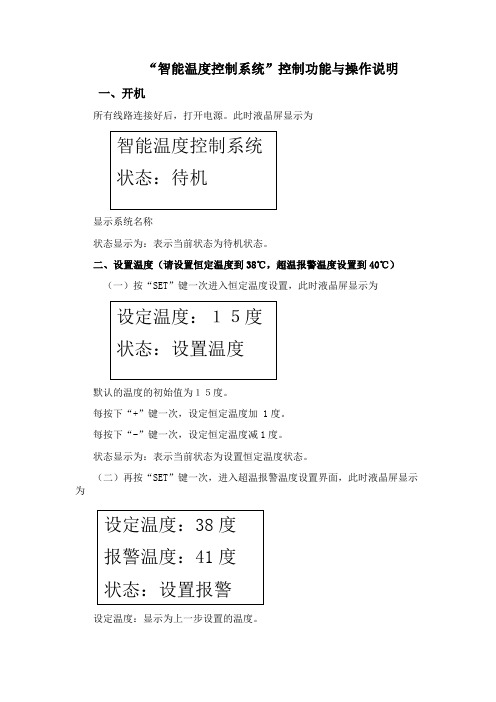
“智能温度控制系统”控制功能与操作说明一、开机所有线路连接好后,打开电源。
此时液晶屏显示为显示系统名称状态显示为:表示当前状态为待机状态。
二、设置温度(请设置恒定温度到38℃,超温报警温度设置到40℃)(一)按“SET”键一次进入恒定温度设置,此时液晶屏显示为默认的温度的初始值为15度。
每按下“+”键一次,设定恒定温度加 1度。
每按下“-”键一次,设定恒定温度减1度。
状态显示为:表示当前状态为设置恒定温度状态。
(二)再按“SET”键一次,进入超温报警温度设置界面,此时液晶屏显示为设定温度:显示为上一步设置的温度。
每按下“+”一次,设定报警温度加 1度。
每按下“-”一次,设定报警温度减1度。
注意:报警温度默认为20度,设置的报警温度应大于设定温度2至4度。
状态显示为:表示当前状态为设置报警温度状态。
三、运行、返回(一)按一次“OK”键,电路开始运行,显示为设定温度:显示为以前设定的所需温度。
报警温度:显示为以前设定的报警温度。
温度:显示为在加热运行过程中的温度,在加热运行中温度应有变化显示。
状态显示为:表示当前状态为运行状态。
说明:1、如当前温度小于设置温度15度以下,加热方式为一档全速加热(脉冲全为低)。
2、如果当前温度小于设置温度10到15度之间,加热方式为二档中速加热(脉宽占空比为二分之一)。
3、如果当前温度小于设置温度5到10度之间,加热方式为三档中速加热(脉宽占空比为四分为一)。
4、如果当前温度小于设置温度5度时,加热方式为四档慢速加热(脉宽占空比为八分一)。
5、如果当前温度小于设置温度1度时,加热方式为五档缓慢加热,当前温度达到设置温度时,加热停止。
6、在运行过程中再次按下“OK”键,系统返回到“待机”状态。
四、超温报警如果当前温度大于或等于报警温度,此时显示为此时系统处于报警状态,系统停止加热、蜂鸣器报警、风扇旋转模拟降温。
智能温控仪表说明书

XMT □7000系列智能温度调节器使用说明书一、概述XMTX7000型智能温度调节器一种高性能、高可靠性的经济型智能型工业温度调节仪表,广泛应用于机械、化工、陶瓷、轻工、冶金、石化、热处理等行业的自动温度控制。
二、技术规格●测量精度:0.5级(±0.5%F ±1);注:仪表对B 分度号热电偶在0-400℃范围内可进行测量,但无法保证测量精度。
●采样速率: >2次/秒●调节方式:智能PID 调节,依据不同的PID 参数可组成P (二位式)、PI 、PD 、PID 调节; ●输出方式:继电器触点、电平信号、过零脉冲、模拟量等可定制。
●报警方式:上限(或上偏差)、下限(或下偏差);●具有手动控制功能,且手动自动无扰切换。
●电源:190V ~240V(AC),/50-60HZ 。
●电源消耗: ≤5W●环境温度:0-50℃,35%~85%RH (无冷凝)●测量范围:K (-50-+1350℃)、S (-50-+1750℃)、T (-200—+400℃)、E (-50—1000℃)、 J (-50-1000℃)、B (50—1800℃)、N (-20—1300℃)、WRe(-20-2300℃)、 CU50(-50.0-+150.0℃)、PT100(-200—+650℃)、PT100(-199.9—199.9℃), 线性输入:-1999—+9999由用户定义●面板尺寸:96×96mm 、160×80mm 、80×160mm 、48×96mm 、96×48mm 、72×72mm 、48×48mm ●开口尺寸:92×92mm 、152×76mm 、76×152mm 、45×92mm 、92×45mm 、68×68mm 、44×44mm三、面板说明(72X72面板为例)四、操作说明仪表上电后,PV 窗口显示输入类型,SV 窗口显示量程,然后PV 窗口显示测量值,SV 窗口显示设定值。
汽车工业中的智能座椅控制技术教程

汽车工业中的智能座椅控制技术教程智能座椅控制技术在汽车工业中的应用越来越受到重视。
随着人们对舒适和安全性的追求不断提高,汽车制造商不仅关注车内空间和座椅的外观设计,还注重如何通过技术创新提供更好的座椅控制体验。
本文将介绍汽车工业中的智能座椅控制技术,包括功能和应用领域。
一、智能座椅控制技术的功能:1. 座椅姿态调节:智能座椅控制系统可以根据乘客的身体姿势和体重分布,实现座椅的自动调节。
通过调整座椅的倾斜角度、高度和支撑力等参数,可以提供乘坐者更合适的姿势,减少驾驶疲劳和不适感。
2. 座椅按摩和通风功能:智能座椅控制系统配备按摩和通风装置,可以通过空气压力和振动等方式提供舒适的按摩和通风效果。
这些功能可以缓解乘客长时间驾驶后的身体疲劳和不适。
3. 座椅加热和冷却功能:智能座椅控制系统还可以根据乘客的需求,调节座椅的温度。
在寒冷的天气中,座椅加热可以提供温暖和舒适的乘坐体验;而在炎热的夏天,座椅冷却功能可以让乘客感到清爽。
4. 座椅记忆功能:智能座椅控制系统可以记忆乘客的座椅偏好和乘坐姿势。
当乘客再次乘坐汽车时,座椅可以自动调整到之前保存的位置和参数,提供个性化的乘坐体验。
5. 座椅安全监测:智能座椅控制系统还可以通过传感器实时监测乘客的身体状况,以确保驾驶乘客的安全。
例如,当系统检测到乘客长时间未活动或身体姿势不当时,可以触发警报或自动调整座椅以防止乘客疲劳和意外伤害。
二、智能座椅控制技术的应用领域:1. 豪华汽车市场:智能座椅控制技术在豪华汽车市场上得到广泛应用。
豪华汽车制造商通过提供高级座椅控制系统,吸引消费者购买他们的产品。
例如,一些豪华汽车品牌为了迎合高端消费者的需求,推出了具有多种座椅调节功能的座椅,如按摩、通风、加热和冷却等。
2. 商务车和长途客车:商务车和长途客车中的智能座椅控制技术主要关注乘客的舒适性和安全性。
这些座椅通常具备记忆功能,可以根据乘客的身体尺寸和乘坐姿势自动调节,提供最佳的乘坐体验。
- 1、下载文档前请自行甄别文档内容的完整性,平台不提供额外的编辑、内容补充、找答案等附加服务。
- 2、"仅部分预览"的文档,不可在线预览部分如存在完整性等问题,可反馈申请退款(可完整预览的文档不适用该条件!)。
- 3、如文档侵犯您的权益,请联系客服反馈,我们会尽快为您处理(人工客服工作时间:9:00-18:30)。
ST04-M
汽车座椅智能温控系统
产品特点
•汽车座椅智能温控系统是我公司根据多年从事汽车座椅舒适类产品的经验最新开发集自动开关、自动控温为一身的全自动产品。
它具有智能控温功能,无需开关控制,自动检测汽车室内温度。
当温度小于设定值时,系统自动启动为座椅加热。
同时根据车内温度的变化自动调节温控时间,营造人体舒适的乘坐环境。
温控性能
•汽车启动后,座椅智能温控系统会自动检测车内的环境温度。
当温度低于13℃时,系统会自动开启为座椅持续加热。
当座椅表面达到饱和温度时(38℃),系统停止持续加热,改为间断加热。
使座椅表面始终维持在35℃左右,以保持人体的舒适温度。
升温性能
•将系统安装到座椅中,座椅放置在-20℃环境中2小时后,接通电源。
进行升温性能测试。
•按上述过程分别进行环境温度在-10℃、0℃、10℃、13℃的测试,测试结果见下图
安装及测试方法
安装:
• 1. 本产品电源线端由+12V火线(红色)、ON线(黄色)和地线(黑色)构成。
接线过程与其他同类座椅加热产品相同(注:温度控制器模块-----黑盒建议前座固定安装在座椅底部位置,后座的固定在后靠空隙或适当位置,一切根据实际情况确定)
• 2. 座椅加热垫安装方法与其他同类产品有所不同,以全车产品为例:除司机座椅外其他座椅增加了压力传感器(注:压力传感器需安装在座椅海绵胎与座椅加热垫之间,固定在座中部位置为益(撕去传感器上的3M胶条粘在相应位置)。
压力传感器装好后引线弯曲一下,防止座椅上下收缩扯断引线,然后再安装座椅加热垫,安装方法与其他同类产品相同。
简单测试方法:
•安装结束后先将温度控制器模块中的温度传感器探头插入事先准备好的冰水中5秒钟,然后
启动汽车为加热垫系统供电。
•系统会在30秒钟内探测环境温度,之后系统开始工作。
司乘人员会感到座椅逐渐变热,说明系统功能正常。
如在线束中串联一块电流表,电流表会显示电流的大小,效果更加明显。
(测试后如需关闭加热系统可关闭钥匙门,再次启动汽车如车内环境高于13℃系统将不工作)
北京朗智亿成汽车系统有限公司
企业简介:
朗智亿成汽车系统有限公司
坐落于风景优美、交通便利的北
京市昌平区中关村科技园区,是
一家集研发、生产、销售、服务
于一体的、中外合资的高新技术
企业,是中国汽车舒适类配件的
旗舰品牌。
公司成立了一个明星级的技术专家顾问团队,他们分别是清华大学和合肥工业大学的汽车专业的权威专家、一汽二汽等国内著名汽车厂商的总工程师。
这使公司从一开始就有了高的起点与持续改进的动力。
生产流水线:
•先进的设备。