CTS使用说明书
CTS 6441-174A Compact Guide Rod Cylinder说明书
ROD
SHARP EDGE OF
A
RETAINING RING FACES
ROD SEAL
OUTWARD AS SHOWN (NOTE ORIENTATION)
BODY
SECTION A-A
FIGURE 2
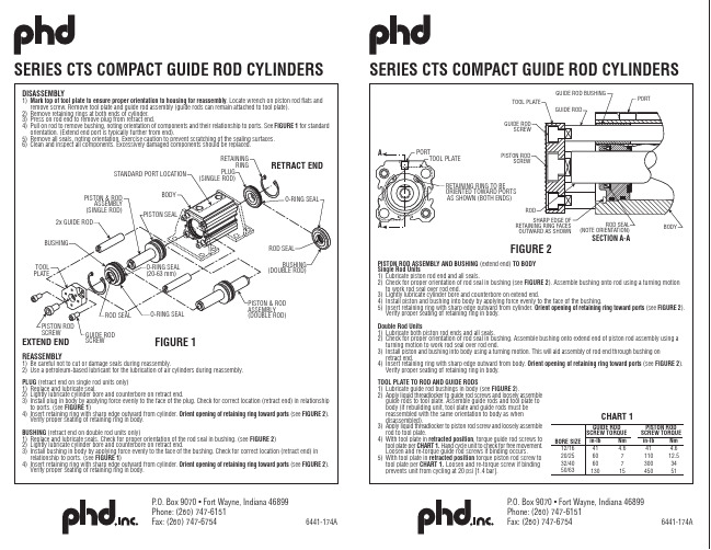
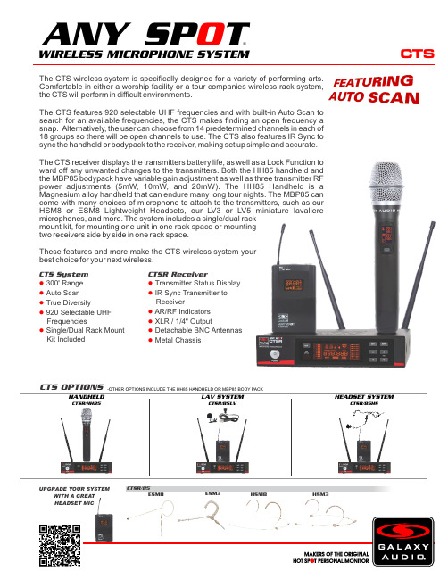
PISTON ROD ASSEMBLY AND BUSHING (extend end) TO BODY Single Rod Units 1) Lubricate piston rod end and all seals. 2) Check for proper orientation of rod seal in bushing (see FIGURE 2). Assemble bushing onto rod using a turning motion
TOOL PLATE
GUIDE ROD SCREW
GUIDE ROD BUSHING GUIDE ROD
PORT
A
PORT
TOOL PLATE
CTS免疫细胞SR产品说明书

Comparable expansion and transduction of CART-19 cells in human AB serum and CTS Immune Cell SR
Cded in CTS OpTmizer supplemented with human serum or CTS Immune Cell SR show similar growth kinetics and total fold expansion after two weeks in culture. Left panel: Growth kinetics from 1 representative donor. Right panel: Fold expansion of total T cells at the end of culture (day 12). Bars represent averages of 4 normal donors.
CTS Immune Cell SR supports T cell lentiviral vector transduction when compared to human sera.
CART-19 cells grown in CTS OpTmizer with CTS Immune Cell SR supplementation showed similar potency and efficacy as control CART-19 grown in CTS OpTmizer with human serum as measured by tumor burden bioluminescence (top) and animal survival (bottom panel).
CTS无线系统产品说明书
CTSThe CTS wireless system is specifically designed for a variety of performing arts. Comfortable in either a worship facility or a tour companies wireless rack system, the CTS will perform in difficult environments.The CTS features 920 selectable UHF frequencies and with built-in Auto Scan to search for an available frequencies, the CTS makes finding an open frequency a snap. Alternatively, the user can choose from 14 predetermined channels in each of 18 groups so there will be open channels to use. The CTS also features IR Sync to sync the handheld or bodypack to the receiver, making set up simple and accurate.The CTS receiver displays the transmitters battery life, as well as a Lock Function to ward off any unwanted changes to the transmitters. Both the HH85 handheld and the MBP85 bodypack have variable gain adjustment as well as three transmitter RF power adjustments (5mW, 10mW, and 20mW). The HH85 Handheld is a Magnesium alloy handheld that can endure many long tour nights. The MBP85 can come with many choices of microphone to attach to the transmitters, such as our HSM8 or ESM8 Lightweight Headsets, our LV3 or LV5 miniature lavaliere microphones, and more. The system includes a single/dual rack mount kit, for mounting one unit in one rack space or mounting two receivers side by side in one rack space.These features and more make the CTS wireless system your best choice for your next wireless.CTSR/85ESM8HSM3HSM8ESM3CTS OPTIONS-OTHER OPTIONS INCLUDE THE HH85 HANDHELD OR MBP85 BODY PACKI RS Y NCCTS System 300Range ●' Auto Scan ● True Diversity● 920 Selectable UHF ● FrequenciesSingle/Dual Rack Mount ● Kit IncludedCTSR ReceiverTransmitter Status Display ● IR Sync Transmitter to ● ReceiverAR/RF Indicators ● XLR / 1/4 Output●" Detachable BNC Antennas ● Metal Chassis●LAV SYSTEMCTSR/85LVHEADSET SYSTEMCTSR/85HSHANDHELDCTSR/HH85WIRELESS MICROPHONE SYSTEM®ANY SP TO UPGRADE YOUR SYSTEMWITH A GREAT HEADSET MICSpecifications subject to change without notice.V20190422601 E. Pawnee Wichita, KS 67211 316. 263.2852 FAX 316.263.0642 Distributed in Canada by Audio Distributors International (ADI ) 1275 Newton, unit 6 Boucherville, QC J4B 5H2 Canada450.449.8177 FAX 450.449.8180CTSSpecifications:CTS SystemAvailable Frequencies: 920Transmitter Output Level: 5 mW, 10 mW, 20 mW Band: UHF FrequencyOperating Range: Under Typical Conditions 300' (92 m), actual range depends on RF signal absorption, reflection, and inference. Audio Frequency Response: (+/-3dB) 60Hz - 16KHzTotal Harmonic Distortion: (+/-30kHz deviation, 1kHz tone): <1%Dynamic Range: >90dB A-weightedOperating Temperature Range: 14°F to 122°F (-10°C to +50°C),battery characteristics may limit this rangeIncluded Accessories: Single/Dual Rack Kit, Antenna Plugs x2,Power Supply, Antennas x2, 1/4" to 1/4" Audio Cable x1, Quick Start Guide Receiver (CTSR)Audio Output Level (+/-30kHz deviation, 1kHz tone): XLRConnector (into 600 Ohm load), 1/4" Connector (into 3k Ohm load)Output Connections: 1 Male XLR Balanced, 1/4" UnbalancedOutput Impedance: XLR connector 200 Ohms, 1/4" connector 1k Ohms XLR Output: Impedance balanced Pin 1: Ground (cable shield)Pin 2: Audio +Pin 3: No Audio -Sensitivity: -102dBm Image Rejection: >90dBCasing: Metal Chassis EIA STANDARD 1/2 UDimensions: 1.7" x 8.3" x 6.3" (45 x 212 x 160mm) (HxWxD)Weight: 31.7 oz (900 g)Power Requirements: 12Vdc at 500 mA,supplied by external power supplyDynamic Cardioid Handheld Transmitter (HH85)Max Audio Input Level: -4.44dBv (-3 gain)Gain Adjust: software control -3dB to +9dB in 3dB steps RF Output: 5 mW, 10 mW, 20 mW Frequency Response: 60Hz - 15kHzDimensions: 9.68" x 2.08" (246 x 53mm)(LxDia.)Weight: 8.8 oz (250 g) (without batteries)Power Requirements: 2 “AA” Batteries, alkaline or rechargeable Battery Life: About 12 hours (alkaline)Body Pack Transmitter (MBP85)Max Audio Input Level: -6dBV (-3 gain)Gain Adjust: -3dB, 0dB, +3dB, +6dB, +9dB RF Output: 5 mW, 10 mW, 20 mW Input Impedance: 470k OhmsDimensions: 2.51" x 3.85" x 0.90" (64 x 98 x 23 mm)(HxWxD)Weight: 3.17 oz (90 g) (without batteries)Power Requirements: 2 “AA” Batteries, alkaline or rechargeable Battery Life: About 12 hours (alkaline)WIRELESS MICROPHONE SYSTEM®ANY SP TO CTSR ReceiverBACK VIEWTOP VIEWMBP85HH85。
CTS-3000说明书

3.2.10.2 定量线………………………………………………………………………21
3.2.10.3 评定线………………………………………………………………………21
3.2.10.4 增益校正…………………………………………………………………22
3.2.11 存储 主菜单……………………………………………………………22
3.2.13 输出 主菜单………………………………………………………………23
3.2.13.1 亮度……………………………………………………………………23
3.2.13.2 报警器……………………………………………………………………23
3.2.13.3 打印机……………………………………………………………………23
3.3.4 屏幕打印/记录键 …………………………………………………………27
3.3.5 回波显示缩放键 ……………………………………………………………27
第4章 检测应用
4.1 仪器的校准方法和步骤……………………………………………………………28 4.1.1 探头参数设置……………………………………………………………………28 4.1.2 工件参数设置……………………………………………………………………29
3.3 其它专用功能键的操作……………………………………………………………26
3.3.1 增益量减少键 / 增益量增加键………………………………………………26
3.3.2 增益步进调节键
…………………………………………………………26
3.3.3 显示冻结键 *…………………………………………………………………27
3.2.11.1 存储号……………………………………………………………………22
Spears EverTUFF CTS CPVC 热水和冷水管道系统说明书

Special Pipe - Spears® CTSSpears®EverTUFF® Copper Tube Size (CTS) CPVC is a complete hot and cold water plumbing system consisting of pipe, fittings and solvent cement for plumbing applications. Spears®EverTUFF® CTS CPVC pipe is easily joined using solvent cement welding, is light weight, thermally efficient and code approved to provide cost-effective long-term system service.Product StandardsSpears®EverTUFF® CTS pipe and fittings are manufactured in strict compliance to ASTM D 2846, Standard Specification for Chlorinated Poly (Vinyl Chloride) (CPVC) Plastic Hot and Cold-Water Distribution Systems. This standard defines requirements for materials, workmanship, dimensions, tolerances, pressure-bearing capability, and thermocycling resistance. Spears®EverTUFF® CTS SDR 11 plumbing pipe and fittings are manufactured to specifications in accordance with this standard. SDR series pipe is based on an outside-diameter-to-wall thickness ratio. This is a constant regardless of pipe diameter, therefore all sizes of pipe carry the same pressure rating of 100 psi @ 180°F and is suitable for use with commercial hot water. Performance TestingSpears®EverTUFF® CTS CPVC pipe is tested and independently certified by NSF International to the requirements of ASTM D 2846 under NSF® Standard 14 and for use in potable (drinking) water service under NSF® Standard 61.Code ApprovalsMajor building codes have approved the use of CPVC piping as an acceptable material for plumbing systems, provided the piping conforms to applicable industry standard's and has been listed by a third party for conformance to NSF® Standard 14 and/or NSF®Standard 61 requirements. Code bodies that accept the use of CPVC include BOCA National Plumbing Code, National Standard Plumbing Code, SBCCI Standard Plumbing Code, International Plumbing Code, and the Uniform Plumbing Code to name a few. The user should determine approval and installation requirements according to local code having jurisdiction prior to use. DimensionsCPVC CTS Series pipe shall be manufactured in strict accordance to the requirements of ASTM D 2846 to SDR 11 dimensions and tolerances. Each production run of pipe manufactured in compliance to this standard, shall also meet or exceed the test requirements for materials, workmanship, burst pressure, flattening resistance, and extrusion quality and dimensions as defined in ASTM D 2846. This pipe shall be produced in CTS diameters (1/2" through 2" sizes) to SDR 11 specifications.NominalPipeSize (in.)AverageO.D.O.D.TOLAverageI.D.Min.WallRating @Wt./ft.PSI PressureRating @73°F180°F 1/20.625±.0030.4690.0680.0904001003/40.875±.0030.6950.0800.1494001001 1.125±.0030.9010.1020.2404001001-1/4 1.375±.003 1.1050.1250.3534001001-1/2 1.625±.004 1.3090.1480.4894001002 2.125±.004 1.7160.1930.829400100 PIPE SIZES SHOWN ARE MANUFACTURED IN STRICT COMPLIANCE WITH ASTM D 2846 ASTM STANDARD D 1784 MATERIAL EQUIVALENTS: Cell Classification 23447 = PVC Type IV Grade I CPVC = CPVC 4120Pressure RatingsThe Spears® CPVC system, including the joint, has a continuous rated working pressure of 100 psi at 180°F or 400 psi at 73°F. CPVC systems have the capability to withstand short term temperature/pressure increases above 100 psi at 180°F, as evidenced by their ability to consistently surpass the 48-hour, 150-psi Uniform Building Code test at 210°F. CPVC pipe should not be used where temperatures will consistently exceed 180°F.Pressure-Temperature De-Rating FactorsFor CTS CPVC 4120 SDR 11 Piping Systems°F Factor Rating, PSI73 1.0040080 1.00400900.913601000.823251200.652601400.502001600.401601800.25100The pressure de-rating factor is the same for all pipe sizes. Example: Determine the maximum allowable operating pressure for a CTS CPVC piping system with an operating temperature of 140°F. Using de-rating factor of 0.50 for 140° from the above chart, the maximum allowable operating pressure = 400 x 0.50 = 200 psi.InstallationInstallation shall be in accordance with the requirements of the local code having jurisdiction, the solvent cement manufacturer recommendations, and Spears® publication CTS-3, CPVC CTS Products Design and Installation Manual.Joining MethodsSpears®EverTUFF® CTS CPVC pipe is easily joined by standard solvent cementing process, threaded connections and flange assembly Solvent Cement Welding.Made in the U.S.A.Suitable for Oil-Free air handling to 25 psi, not for distribution of compressed air or gasSee Spears® Product Sourcebook for product offerings Page 68Hot & Cold Water Distribution SystemsSpecial Pipe - Spears® CTSSolvent Cement WeldingThis is the most common joining method used with CTS CPVC. See Installationsection for industrial pressure pipe for basic solvent cementing guidelines.CTS Solvent Cement SelectionCodes require use of solvent cement conforming ASTM F 493 and designatedspecifically for use with CTS CPVC products in accordance with ASTM D 2846.Spears®EverTUFF® CTS-5 CTS CPVC "One-step" (primerless) cements maybe used without primer if codes permit, or may be used with a primer whererequired by code. - Always CHECK LOCAL CODES.Set and Cure TimesPipe and fitting joint assembly must be allowed to set without any stress on thejoint for one to five minutes depending on the pipe size and temperature.Following the initial set period, the assembly can be handled carefully.FOLLOW THE CEMENT MANUFACTURER'S RECOMMENDED CURE TIMESPRIOR TO PRESSURE TESTING. - FAILURE TO DO SO WILL RESULT INJOINT FAILURE.Minimum Cure Time Prior to Testing at 150 psi with ColdWater (based on use of one-step CPVC cement or two-stepcement systems)Pipe Size (in.)Ambient Temperature During Cure Time>60°F40°F - 60°F<40°F3/8 1 hr 2 hrs 4 hrs1/2 1 hr 2 hrs 4 hrs3/4 1 hr 2 hrs 4 hrs1 1 hr2 hrs 4 hrs1-1/4 2 hrs 4 hrs8 hrs1-1/2 2 hrs 4 hrs8 hrs2 2 hrs 4 hrs8 hrs •NOTE Wait 24 hours prior to putting system into hot water service when installed at cure temperatures above 60°F; wait 48 hours prior to putting system into hot water service when installed at cure temperatures below 40°F Solvent Cement Joining.Wall PenetrationBuilding codes require that a fire-rated wall or floor must be sealed back to its original integrity when penetrated. Several sealants and materials are suitable for use with Spears®EverTUFF® CTS CPVC pipe to construct an appropriate UL Classified fire-rated penetration system. When installed properly, these systems will provide a two-hour fire rating. Consult local building code requirements.•NOTE Caution: Certain fire-stopping sealants and components contain stress cracking agents and other chemicals which may cause damage to CPVC piping; contact the appropriate manufacturer for compatibility with CPVC prior to use.•NOTE When installing CPVC in areas where the system must be drained to protect it from freezing, the lines must be sloped to drain.Underslab InstallationsSpears®EverTUFF® CTS CPVC products are approved for underslab installations (with joints) in all model-plumbing codes. When performing underslab installations, it is important to support the tube evenly on a smooth surface. The bedding and backfill should be sand or clean soil that is free from sharp rocks and other debris that could damage the pipe.Underslab installations that contain joints must be pressure tested before pouring the slab. NOTE: IAPMO IS 2098, "Installation Standard for CPVC Solvent Cemented Hot and Cold Water Distribution Systems," requires a test at 150 psi for 2 hours. The pipe should be sleeved where it penetrates the slab, along with construction joints within the slab. Spears®EverTUFF® CTS pipe is also manufactured in coils for underslab installations to eliminate joints. When turning coiled pipe up through a slab, into walls, etc., make sure the pipe does not kink. Sections of pipe that contain kinks must be cut out and replaced. Freeze Protection/Sunlight ExposureCPVC piping must be protected from freezing in all installation locations. Attention shall be paid to local insulating techniques and codes that require a particular method. Use only methods and materials suitable for use with CPVC piping. Where freezing is not an issue, CPVC shall not be installed so as to be subject to direct sunlight after installation and not installed on the surface of a building, unless protected by a covering or a chemically compatible paint, such as water based Latex.Hose Bibb InstallationHose bibbs are to be connected only to metal system components which are adequately anchored to the building structure. CPVC plastic systems must terminate in the wall.Water Heater ConnectionsBefore attempting to use Spears®EverTUFF® CTS CPVC in water heater connections, determine if local plumbing codes contain detailed requirements for connections to gas or electric storage-type heaters.DO NOT use Spears®EverTUFF® CTS CPVC products with commercial-type, non-storage water heaters.For areas where local plumbing codes do not have requirements, the following information can be used as a guide for water heater connections:• On electric water heaters, CPVC can be joined directly to the heater, using metal-to-CPVC transition fittings.• On high-efficiency gas water heaters that use plastic vent piping, CPVC can be joined directly to the heater in the same way as an electric water-heater connection.• On all other gas water heaters, there should be at least 6" of clearance between the exhaust flue and any CPVC tubing. A minimum of 6" metallic pipe should connect directly to the heater so that the CPVC tubing cannot be damaged by the buildup of excessive, radiant heat from the flue.• A temperature/pressure relief valve should be installed so that the sensing element contacts the water at the top of the heater.Page 69Suitable for Oil-Free air handling to 25 psi, not for distribution of compressed air or gas Spears® Manufacturing CompanySee Spears® Product Sourcebook for product offeringsSpecial Pipe - Spears ®CTS• Spears ®EverTUFF ® CTS CPVC products are approved by all model codes for use as relief-valve drain lines. A metal-to-CPVC transition fitting should be used to connect the tubing to the relief valve, with the tubing continued to the outlet. Both horizontal and vertical pressure relief drain should be supported every 3 feet. For horizontal runs, slope the tubing toward the outlet. Pipe must discharge to the atmosphere at an approved location.• Instantaneous water heaters (i.e., under sink units) require at least 6" of metallic pipe connected to heater inlet and no CVPC installed downstream.TRANSITION JOINTS AND FITTINGSSpears ®EverTUFF ® CTS CPVC pipe can be connected to copper, brass, valves, and other materials using a variety of transition fittings including unions, compression fittings, specially reinforced male and female adapters, flanged joints, grooved joints and other readily available transition fittings.Do not thread CPVC pipe and do not use regular CPVC female threaded fittings. Regular CPVC male threaded fittings shall only be used on cold waterapplications. Special reinforced male adapters, female adapters and otherfittings with brass threads are recommended for hot water applications andthreaded transitions to metal pipe. All approved threaded CPVC joints must beaccessible. (See also Water Heater Connections section for additional installation details).Standard compression fittings with brass ferrules can be used; however, PTFE tape must be applied over the brass ferrule to compensate for the dissimilarthermal expansion rates between the brass and CPVC. Caution must beexercised to prevent over tightening of compression fittings. Use extreme care when soldering any metal system to prevent flame contact with or heat distortion in CPVC pipe and fittings.Assembling Threaded Connections Threaded connections require the application of a thread sealant that is compatible with CPVC material. Spears ® recommends the use of Spears ®BLUE 75™ Thread Sealant. Apply sealant to the male threads only. Make sure all threads are covered. DO NOT clog the waterway with excess sealant. If PTFE tape is used, Spears ® recommends a thickness of at least .0035" that meets or exceeds military specification, MIL-T-27730A. DO NOT use a combination of tape and thread sealant on the same joint. Apply PTFE tape in the direction of the threads by starting with the first full thread and continuing over the entire thread length. Make sure all threads are covered. Generally, 2 - 3 wraps are sufficient to produce a watertight connection.DO NOT over-torque any threaded connections. Generally, one to two turns beyond finger-tight are required for a threaded connection. Factory testing hasindicated that 10 - 25 ft-lbs of torque is adequate to obtain a leak-free seal.Spears ® recommends the use of a strap wrench when installing threadedconnections.Hanger/Support SpacingSpears ®EverTUFF ® CTS CPVC pipe is rigid, it requires fewer supports than flexible, plastic systems. Vertical runs should be supported at each level so that the weight of the run is not placed on a fitting or a joint. Horizontal runs require support every 3 feet for 1/2" - 1" diameter pipe and every 4 feet for 1-1/4" and larger diameters. Support spacing should be in accordance with applicable local codes. Horizontal runs must be braced so that the stress loads (caused by bending or snaking) will not be placed on a fitting or a joint. Hanger support spacing information is shown in Table A.Spears ® recommends that hangers, designed for supporting CPVC, be used tosupport CPVC piping. However, some hangers, designed for steel pipe, may be used if their suitability is clearly established. These hangers must be selected toaccommodate the specific pipe size. In addition, they cannot contain rough orsharp edges that contact the pipe, and they must not bind the pipe from axial movement that is caused by expansion and contraction.Pipe Size (in.)Maximum Hanger Support Spacing 3/8 3 ft 1/2 3 ft 3/4 3 ft13 ft 1-1/4 4 ft 1-1/2 4 ft 24 ft Thermal Expansion All piping systems expand and contract with changes in temperature. This issue must be addressed with appropriate system design to prevent damage to thesystem. Spears ®EverTUFF ® CTS CPVC pipe will expand or contract approximately 3.8 inches per 100 feet of pipe with every 100°F of temperaturerise or fall. The effects of expansion/contraction are usually absorbed by the system at changes of direction in the piping. In other words, long, straight runs of piping are more susceptible to experiencing measurable movement with changes in temperature. As with other piping materials, the installation of an expansion loop or offset is required on long, straight runs which will allow the piping system to absorb the forces generated by expansion/contraction without damage. The rate of expansion does not vary with pipe size. The effects of expansion/contraction are more pronounced on hot water lines. See Thermal Expansion & Contraction section under Engineering and Design Data for Industrial Piping in this manual for information on calculating movement andexpansion loops.System TestingOnce the system has been installed and allowed to cure properly, the systemshall be tested in accordance with applicable code requirements. When testingwith water (hydrostatic testing), the system must be slowly filled with water andthe air bled from the highest and furthest points in the system before test pressure is applied. Air must be removed from piping systems to prevent it from being locked in the system when pressure is applied. Failure to do so could beharmful to job site personnel should a failure occur. If a leak is found, the affected product must be cut out and discarded. A new section can be installedusing couplings or other approved means.Made in the U.S.A.Suitable for Oil-Free air handling to 25 psi, not for distribution of compressed air or gasSee Spears ® Product Sourcebook for product offeringsPage 70。
HDMI CTS Sink Test Library 使用手册说明书

P A D -T -M :3574.3259.02/01.00/C I /1/E NHDMI CTS Sink Test Library ManualM a n u a lB r o a d c a s t a n d M e d i a2115.7916.02–03The manual describes the content of the HDMI CTS sink test library(2115.7900.00).The library is part of: R&S®VT-B23622115.7700.06R&S®VT-B23632115.7716.06©2016Rohde&Schwarz GmbH&Co.KGMuehldorfstr.15,81671Munich,GermanyPhone:+49894129-0Fax:+4989412912164E-mail:**********************Internet:Subject to change–Data without tolerance limits is not binding.R&S®is a registered trademark of Rohde&Schwarz GmbH&Co.KG.Trade names are trademarks of the owners.The following abbreviations are used throughout this manual:R&S®XYZ123is abbreviated as R&S XYZ123HDMI CTS Sink Test Library ContentsContents1Getting Started (4)1.1Contents of the Disk (4)1.2Version History (4)1.3System Requirements (4)1.4Installation Instructions (5)2Using the Library (5)HDMI CTS Sink Test Library Getting Started1Getting StartedThis disk contains HDMI signal files that are used in the HDMI generator application ofthe instrument.1.1Contents of the Disk● This document● Install.bat● HDMI.exe● 7z archive files1.2Version HistoryFor information on the current firmware version refer to the release notes of theinstrument.1.2.1Version1.20Updated HDR test pattern with new video content.Updated3D test pattern with3D picture content.1.2.2Version1.10New HDR test pattern.Updated test pattern for21:9testing:circle element added to determine the correctaspect ratio.1.2.3Version1.00Initial release.1.3System RequirementsThe Rohde&Schwarz Web Configurator shows you the required hardware andsoftware options.It is provided in the Internet:On the Rohde&Schwarz Home Page(),go to the instrument-specific site and configure yourproduct.If you need any further information,refer to the help of the Rohde&SchwarzWeb Configurator.HDMI CTS Sink Test Library Using the Library1.4Installation InstructionsTo install the HDMI CTS sink test library on the instrument,the following procedure isrecommended:1.Copy the complete content of the disk to a USB flash memory.2.Connect the USB flash memory to the instrument.3.Open the file explorer and navigate to the folder on the USB flash memory thatcontains the copied disk content.4.Execute the Install.bat file and wait for the installation routine to complete thesetup.2Using the LibraryThe content of the library is integrated in the CTS test cases of the HDMI generatorapplication.For further details refer to the user manual of the instrument.。
cts i28说明书
cts i28说明书
1、按菜单,进入主菜单键,选择“程序设置”。
2、再点击“程序设计”,按照菜单,设置相应参数即可。
3、选择测试类型:如果判断标准以压降为单位,“压力衰减-p”这种模式;如果判断标准以另一个为单位,选“压力衰减-泄漏标准”这种模式。
4、设置测试时间:把测试产品相应的时间输入即可。
5、设置测试压力类型:输入“测试产品的压力即可”,最大、最小压力比目标压力大或小相对应设置。
6、设置产品的标准:产品漏多少的参数在此设置,主要设置压损高限,举例:标准是50pa,就压损高限50pa,压损低限-50pa。
CTS 1010S钢轨焊缝超声探伤仪 使用说明书

CTS 1010S钢轨焊缝超声探伤仪使用说明书cts-1010s钢轨焊缝超声探伤仪-使用说明书Cts-1010s钢轨焊接超声探伤仪亲爱的用户:您们好!非常感谢您购买广东汕头超声波电子有限公司超声波仪器分公司的产品,这使我们有机会为您提供服务。
我们将尽最大努力满足您的要求,让您享受超声波仪器分公司产品的卓越性能和质量。
在使用产品之前,请务必仔细阅读本说明书,以便能够正确地进行操作,让您使得顺手,用得顺心。
同时通过手册中的联系方式,可以享受到我们随时准备为您提供的服务。
通过附录,您还可以了解到更多的关于仪器使用方面的知识,有利于更恰当地使用本产品。
我们希望这本“用户手册”能成为我们产品使用过程中的好帮手。
再次感谢您使用我们的产品,希望有更多的机会为您服务!目录1一般安全概述42仪表简介52.1功能和特点52.2主要性能参数62.3仪表板和主要部件说明72.4关键说明82.4.1关键符号和相应含义82.4.2通用旋钮功能92.5仪表菜单流程和说明92.5.1显示屏显示区划分92.5.2菜单列表和说明102.5.3全屏参数的使用143仪器的基本调整和应用163.1仪器的启动、关闭和充电163.1.1启动-关闭。
163.2 163.1.3充电163.2仪器校准173.3如何检测183.4检测过程中一些辅助功能的使用193.4.1自动增益193.4.2波形扩展193.4.3峰值搜索193.4.4报警彩色显示功能13.4.5打开和退出DAC曲线功能203.4.6打开和退出包络功能203.4.7波形比较213.5数据存储和调用213.5.1存储缺陷波形213.5.2使用通道224使用仪器的高级功能224.1连续存储(视频记录功能)224.1.1基本记录和回放224.1.2标记和更改检测位置记录期间234.1.3灵敏度和门调整记录期间234.2测试报告244.3dac曲线制作和删除244.3.1 DAC曲线制作254.3.2dac曲线校正264.3.3单探头DAC曲线报警和存储264.4汉字输入264.4.1拼音输入法274.4.2其他输入274.5数据处理274.6自动校准仪性能284.7校准探头频率295仪器维护和维修295.1锂电池维护295.2仪器维护和维修23025.2.1仪器维护295.2.2仪器维护296服务和技术支持30附录a方波应用31附录B 软件升级方法32附录C连续数据记录操作指南33附录D回放管理软件指南36附录E焊缝GPS位置信息建立指南383。
CTS-22超声波探伤仪使用说明书
CTS-22A/B 超声探伤仪使用说明书1. 概述CTS-22A/B型超声探伤仪系携带式A型脉冲反射式超声探伤仪器,可用交流或电池供电工作。
本仪器采用高性能器件,SMT(即贴片技术)安装和高亮度内刻度示波管,具有工作频率范围宽、探伤灵敏度高、稳定性好、故障率低、显示波形清晰和小型、省电、方便等特点。
仪器可用于金属和部分非金属材料的超声无损检测,尤其适用于流动性大的野外或高架空探伤作业。
2. 主要技术性能2.1工作频率范围接收放大器频带宽度0.5~10MHz。
2.2工作方式单探头发射接收或双探头分别发射接收。
2.3衰减器衰减器总衰减量80dB(20dB×2、2dB×20);<增益>电位器连续调节量0~6dB;衰减器衰减误差:每2dB不大于±0.1dB。
2.4放大线性2~5MHz 1级(JIS Z 2344)。
2.5 抑制电平<抑制>电位器调节范围:垂直刻度的0~80%。
2.6 发射脉冲幅度阻尼电阻50Ω时,约500Vp 。
2.7 发射脉冲重复频率分500、250、125、62.5Hz 四档,与<探测范围>粗调开关同轴调节。
2.8 探测范围10~5000mm(钢纵波);<探测范围>粗调开关分10、50、250mm 及1m(钢纵波)四档,微调由多圈电位器控制。
2.9 时间轴线性不大于1%(JIS Z 2344)。
2.10 脉冲移位距离不小于400mm(钢纵波),由多圈电位器控制。
2.11 配用探头可配用汕头超声仪器研究所生产的普通和窄脉冲系列探头中标称频率为0.5~10MHz 的各种探头。
2.12 探伤灵敏度余量配用2.5Z20N 直探头,JIS-STB-G V15-2试块平底孔反射波高为垂直刻度50%时的灵敏度余量为46dB 以上。
2.13 远距离分辨力2MHz 以上A 级(JIS Z 2344)。
2.14 适用电源AC :220V %,50~60Hz(电源电压可按用户要求改为100V 或1020+-110V);DC :12.5±2V(镍氢电池1.25V×10)。
汕头超声波仪器CTS 4020使用说明书.

电池类型锂电池(7.2V、7.2Ah
工作时间h使用7.2Ah锂电池
≥6 (与背景光亮度有关
工作电压V 6 ~ 9 DC (外部电源,6.0 ~ 8.4 (电池。工作温度℃–10 ~ 50
重量kg约1.94(不含电池
尺寸mm260 ×180 ×95 (宽×高×深
注:不同型号仪器在功能或指标上的差别,见表1。
闸门:控制a、b闸门所必需的功能,以及跟踪闸门设定。
DAC :制作DAC曲线、TCG曲线,以及用DAC、TCG曲线对缺陷回波进行评价的各项功能。
存储:用于存入、调出和删除数据集,以及数据集的其他管理。
预置:配置仪器的其它设定,包括时钟、打印、显示颜色等。
根据需要进行相应的选择,当某一个主菜单被选择时,屏幕右方将显示与该主菜单相关的子菜单内容,详见3.1菜单目录。
DAC+6.0dB
DAC修正
off
a闸门起位*
35.0mm
定量线
DAC+0.0dB
增益校正
0.0dB DAC帮助
评定线
DAC-6.0dB
曲线选择
评定线
∨ ∨
存储存储号
1
∧ ∧
调出ห้องสมุดไป่ตู้
off
测试信息
off
删除所有
off
存入
off
预览
off
转存U盘
off
删除
off
off
转存选项
当前
∨ ∨
预置区域
3区
∧ ∧ ∧
工作频率
1~4MHz
增益微调
双探头
off
检波方式
双向
自动增益
off
CTS Filtered Terminal Blocks说明书

NorthAmerica:+1-800-757-6686•International:+1-508-435-6831•Asia:+65-6481-1466••************************FILTERED TERMINAL BLOCKSEliminate Electromagnetic Interference (EMI)UL Standard 1059 CompliantTerminal BlocksCTS UL-recognized filtered terminal blocks are specifically designedto save time and money for EMI filtering applications. By combininga filtering component with an industry standard terminal block, CTShas created an effective barrier to EMI noise.CTS filtered terminal blocks allow the engineer to eliminate EMIusing an existing mechanical design element combined with the excellent performance of a Pi filter.PCB Mounted Filtered Terminal BlocksCTS latest line of filtered terminal blocks allow engineers the abilityto mount the blocks directly onto the PCB. These filters save laboras well as board space. In addition, the filoffers a wide range ofperformance while meeting specific requirements. It is the perfectEMI solution.SPECIFICATIONS• 2-8 terminals available• Operating temperature: -55°C to 105°C• Working voltage: Up to 250 V AC• Capacitance: Up to 15 nF• DC resistance: 0.01 Ohms max.• Wire sizes to #12 AWG• Screw size: #6-32 or #8-32 head screw• Insertion loss: 65dB up to 10GHz SPECIFICATIONS• Operating temperature: -40°C to 105°C• DC working voltages: 100V DC @ 85°C• Capacitance: Up to 2500 pF• Dielectric withstanding voltage: 707V DC• Insulation resistance: ≥ 10 GΩ• DC current: 12 Amps• DC resistance: ≤ 10 mΩNorth America: +1-800-757-6686 International: +1-508-435-6831 Asia: +65-6481-1466 ******************** EMI/RFI FILTERSCoaxial BroadbandHigh Frequency, Low Pass C FilterL Filter ‘High frequency, small size, excellent capacitance values’Coaxial Broadband EMI/RFI FiltersCTS coaxial broadband EMI/RFI filters have high capacitance values (up to 1.4 μF),and are resin and hermetically sealed. These filters are available to MIL-PRF-15733standards.SPECIFICATIONS• Max. torque: 9 in-lbs (1.04 Nm)• DC resistance: 0.01 Ohms max.• Working voltages up to 280 V DC at 125°C• Insertion loss: Up to 70dB at 1GHz• 4601 series seal tested per MIL-STD-202, Method 112, Condition A°CAPPLICATIONS: Power Supplies, Power Inputs & Outputs, Industrial Controls and Telecommunications Equipment High Frequency, Low Pass EMI/RFI Filters CTS has a wide range of high frequency, low pass filters that are small in size and offer excellent performance. These filters save bulkhead space and eliminate EMI while reducing cost.SPECIFICATIONS • Frequency range 1MHz to 10GHz • Operating temperature: -55°C to +125°C • Capacitance values up to 100,000 pF • Capacitance tolerance (+100%, 0%) (+80%, -20%), or customer specific • Working voltage: 50-2,000 V DC • Current: 5-25 Amps • S uggested mounting torque from 2 in-lbs to 9 in-lbs (0.231 to 1.04 Nm)• H ex nut 0.125 in-0.5 in across the flats• M ax. solder temperature 500°F (260°C)APPLICATIONS: Telecommunications, CATV, Telemetry, Radar, Amplifiers and RF SwitchesPi Filter C Filter Pi Filter C Filter EMI/RFI FILTERS Surface Mount Quick Connect & Bolt-In Filter Plate Assemblies EMI/RFI Surface Mount Filters CTS 4700 series Pi and C filters are used where cost and space savings are a priority and improved insertion loss is required. The filter's unique design makes it suitable for common production soldering processes. The state-of-the-art manufacturing process results in excellent electrical and mechanical performance. The square or round body allows easy handling, positioning and soldering onto the PCB. The 4700 series is another cost effective, quality product from CTS.SPECIFICATIONS • 100 V DC up to 125°C • Dielectric withstanding: 300 V DC • 4700/4701 DC rating: 10 Amps; 4702 DC rating: 20 Amps • Insertion loss: Up to 70dB at 1GHz • Capacitance: 100 pF to 5,000 pF EMI/RFI Filters & Capacitor Assemblies CTS quick-connect and bolt-in filter plate assemblies provide ease of installation and line customization of standard size plates. Filter plates are the most efficient and cost effective solution for filtering multiple lines into or between different system compartments.For higher frequency applications (above 50MHz), filter plates can be more effective than typical surface mount solutions. The natural shielding quality of the plates creates an effective RF barrier that provides excellent insertion loss and isolation for frequencies above 5MHz. The pre-assembled plates greatly reduce the time and resources required to individually install solder or bushing mount filters.CTS quick connect series of filter plates features a base plate with built-in installation clips. These clips allow for cost effective mounting into the system’s bulkhead without the cost associated with traditional hardware.SPECIFICATIONS • Operating temperature: -55°C to 125°C • Capacitance values up to 10,000 pF • Working voltage at 125°C: 100 V DC • Current: 5-10 Amps • No-load insertion loss: 70dB up to 10GHz ‘For use where cost saving is a priority and improved insertion loss is required’CERAMIC CAPACITORS &RESONATORS High Q FactorCircuit MiniaturizationCeramic Trimmer Capacitors CTS leads the way in the miniaturization of ceramic trimmers. The 513 SMT, all-ceramic trimmer capacitor offers outstanding features such as exceptionally smooth tuning, extra miniaturized - 0.196 diameter x 0.100in height max. (4.98 x 2.54mm) ceramic base & dielectric - very stable, high Q factor for ultra high frequency applications, wide temperature range - functional under extreme conditions, SMD on tape and reel - suitable for automatic pick and place, and rugged construction.DISC Ceramic WEECON ® Capacitors Known throughout the industry for quality and reliability, CTS prides itself on maintaining an excellent track record in producing high reliability products.Our DISC ceramic capacitors have three classifications:Temperature Compensating - highest Q, minute capacitiance change with temperature, more stable than glass or mica. Extended Temperature Compensating - finite and repeatable capacitance change with temperature, also high Q and stability.High Dielectric Constant - high capacitance, low dissi-pation factor replaces paper, film, glass, mica in generalpurpose applications.CTS WEECONS ® have long been the industry standardand offer the broadest selection of available ceramicformulations and package sizes. With a capacitancerange of 1 pF to 0.082 mF, WEECON® capacitors offera variety of TC materials and tolerances. The range oftemperature characteristics available make theWEECON ® suitable from the ultra stable requirements oftuned circuits to the general purpose needs for couplingand bypassing.Encapsulated with ahard, bright polymericcoating, these capaci-tors are formulated toprovide mechanicalprotection under nor-mal environmentalconditions.Available in 25, 50, 100 and 500 voltsThickness from 0.1 to 0.175in (depends on voltage)Square sizes from 0.1 x 0.1 in to 0.6 x 0.6inOperates efficiently at -55°C to 125°C SPECIFICATIONS • Operating temperature: -55°C to 125°C • Capacitance range of 1-3 pF max. to 10-60 pF max.• Working voltage: 25-200 V DC • Dielectric strength: 50-500 V DC • Torque from 0.3 in-oz to 6 in-oz (0.035 to 0.693 Nm)APPLICATIONS: Point to Point, PCB, Avionics, Communications Equipment and Instrumentation.SPECIFICATIONS • Sizes: 2, 3, 4, 6, 8, 12mm • Dielectric constant: 9 min., 90 max.• Frequency range: 250MHz — 6GHz*• Electrodes: High density, fired on silver, with tin plating over nickel barrier finish *Higher frequencies available by special order.APPLICATIONS: Voltage Controlled Oscillators (VCOs), Coaxial Resonator Oscillators (CROs), Bandpass Filters, Wireless Devices and Duplexers.Ceramic Coaxial Resonators CTS ceramic coaxial resonators are offered in four sizes and four dielectric constants with a frequency range from 800MHz to 5.9GHz. To ensure superior performance and adequate miniaturization, these parts are made of quality metalized ceramics. CTS offers the best ceramic composition in order to meet all necessary temperature performance, shielding and miniaturization requirements for an endless number of applications.‘Superior performance, extra miniaturized, and high Q factor ’ North America: +1-800-757-6686International: +1-508-435-6831Asia: +65-655-17551L AUNCHING I NNOVATIVE P RODUCTS INTO THE F UTURE◆ Quartz Crystals◆ Clock Oscillators◆ Timing Modules◆ Semiconductor ICsF REQUENCY C ONTROL P RODUCTSEMC P RODUCTS◆ Surface Mount Filters◆ Feed Through Filters◆ Filtered Terminal Blocks◆ Variable TrimmerCapacitors◆ Coaxial Resonators◆ Custom EMI FilterPlate Assemblies◆ Ceramic Disc CapacitorsC ERAMIC C OMPONENTSR ESISTOR P RODUCTSE LECTROCOMPONENTS T HERMAL M ANAGEMENT S OLUTIONS◆ Monoblock Filters◆ Monoblock Duplexers ◆ ClearPlex® Waveguide Filters ◆ClearONE™ Terminators ◆Chip Resistor Arrays◆Current Sensing◆Ultra High Resistance◆ Potentiometers◆Encoders◆ Mini-Joysticks◆ Rotary Switches◆ DIP Switches◆ Trimmer Potentiometers ◆ Sensors and Controls◆ Custom Assemblies◆ Heat Sinks◆ Fansinks◆ ZIF Circuit Card Retainers。
CTS系列单相调压控制器使用说明书

产 品 说 明 书CTS系列单相调压控制器Version Number : 2020.09目录一、选型前注意事项1二、产品简介1三、选型规格表2四、安装使用注意事项3五、面板说明及接线示意图4六、、附加型Z-CTS单相整流调压控制器6七、售后服务7二、产品简介1、额定输入电压2、额定工作电流1、手动电位器调节:2.2-4.7K2、电流自动控制型号:4-20mA3、电压自动控制型号:1-5VDC,2-10VDC1、面板多只LED指示灯,显示调压控制器的工作状态及故障原因,方便有故障时及时维修。
3、PC板采用SMD贴片原件,抗干扰性佳,故障率低。
4、比例式线性输出,控温精确,精度0.3%符合各种负载要求。
2、整机采用铝合金外壳,体积小散热效果佳,100%的引导风扇气流散热。
6、输入方式:4-20mA、1-5VDC、2-10VDC三种方式由P1 JUMP自由切换选择不需更换主机。
5、主电源与PC板工作电压无相序先后关系,使用方便(50HZ-60HZ自动辩识)。
一、选型前注意事项用户订货时须说明:CTS 为可控硅单相交流调压控制器,采用具有国际专利的散热风道与绝缘端子设计而成。
具有结构紧凑、工作指示明晰、安装方便、接线简单、工作可靠等优点。
CTS 调压控制器采用移相触发方式来实现对电压的调节,以便达到控制电压的目的。
它输出电压的范围一般为额定电压的0-98%。
具有缓启动、缓关断,限流,以及过流保护,过热保护等功能。
1、缓启动、缓关断功能:软启动软关断就是指电源投入使用或者给定电压急剧变 化时,输出不会随之急剧变化。
在感性负载场合,可以防止冲击电流与反向高 压冲击电流对可控硅的破坏。
当阶跃性输入时,缓启动缓关断可输出平缓变化。
缓启动、缓关断时间约为2-3秒。
2、全系列内置快速保险丝及过热停止输出保护开关,保护调压控制器和负载。
3、过热保护功能:若环境温度偏高或风机停转时,散热器温度有可能超过80℃时, 调压调功控制器会迅速自动截止全部输出,并完成自锁。
CTS-9006,9008,9009_数字超声探伤仪中文说明书_A07_131030

1~4MHz 0.5~8MHz 2~15MHz
正向 负向 双向 滤波 RF
√
1~4MHz 0.5~8MHz 2~15MHz
正向 负向 双向 滤波 RF √ √ √
AWS.D1.1/D1.5 焊缝等级计算
√度定量计算
曲面修正
√
裂纹测高
√
闸门内回波扩展
√
定时 B 型扫描
专用测厚模块
U 盘短片记录
数据存储容量
300 组
300 组
注:表中打“√”,表示该型号仪器具有此项功能或指标。
√
√ √ √ √ √ √ 500 组
汕头市超声仪器研究所有限公司
本说明书的编写以 CTS-9006 为基准,说明书内的参数和操作方法为 CTS-9006。CTS-9008、 CTS-9009 的操作与其兼容,增加的功能和操作方法请参见附录 D、附录 E。
如有任何疑问,欢迎您按以下联系方式与我们联系:
汕头市超声仪器研究所有限公司(SIUI) 地址:广东省汕头市金砂路 77 号 邮编:515041 电话:0754-88250150 传真:0754-88257355 网址:/ E-mail: siui@
汕头市超声仪器研究所有限公司
DCY2.781.9009/9008/9006SS/A07
目录
前 言........................................................................................................................................................ V 仪器使用注意事项及安全指导................................................................................................................. VII 第 1 章 仪器..........................................................................................................................................1-1
OBT1553B-CTS 型 1553B 电缆测试系统 使用说明书

OBT1553B-CTS型1553B电缆测试系统 使用说明书(版本:2.0)珠海欧比特控制工程股份有限公司地址:广东省珠海市唐家东岸白沙路1号欧比特科技园邮编:519080电话*************传真*************网址:前 言感谢您使用OBT1553B-CTS型1553B电缆测试系统。
为了使您能尽快熟练地操作OBT1553B-CTS型1553B电缆测试系统,我们随机配备了内容详细的使用说明书,在您第一次安装和使用本仪器时,请务必仔细阅读所有随机资料。
基于提高部件及设备性能和可靠性的需要,我们有时会对设备(包括硬件和软件)做一些改动,届时,我们会尽量修改或增加资料,但仍可能在某些描述上与实际改动后的不一致,敬请谅解。
本使用说明书中如有错误和疏漏之处,热切欢迎您的指正。
厂家相关信息z生产企业名称: 珠海欧比特控制工程股份有限公司z生产企业地址: 广东省珠海市唐家东岸白沙路1号欧比特科技园z产品标准编号: OBT1553B-CTSz售后服务单位: 珠海欧比特控制工程股份有限公司z联系方式:地 址:广东省珠海市唐家东岸白沙路1号欧比特科技园电 话:************传 真:************邮 编:519080使用注意事项z 本产品在出厂前已经过充分的检验。
用户在使用前,请先确认它在运输过程中没有受到损坏; z 设备的型号和规格都在设备的外壳上,使用前请先核对一下您手中的产品与订货时的型号是否一致,设备配件是否完整;z 为避免设备受到损坏,请使用设备包装箱进行运输,直至到达安装使用现场;z 存放地点应具备以下条件:防雨、防潮;机械振动要小,防止可能的碰撞。
使用说明书中的标识警告:表示必须照办,以免对操作者造成伤害。
表示必须遵守,以免损坏设备。
有关操作和使用的重要信息及提示。
声明珠海欧比特控制工程股份有限公司拥有此非公开出版的使用说明书的版权,并有权将其作为保密资料处理。
本使用说明书只作为操作、保养和维修产品的参考资料,其他人无权向他人公开此使用说明书。
Thermo Fisher Scientific CTS TrypLE Select产品说明书

CTS™ TrypLE™ Select Catalog Numbers A4738001 and A1285901Pub. No. MAN0007390 Rev.2.0WARNING! Read the Safety Data Sheets (SDSs) and follow the handling instructions. Wear appropriate protective eyewear, clothing, and gloves. Safety Data Sheets (SDSs) are available from /support.Product descriptionTrypLE™, an animal origin-free alternative to porcine trypsin, is a recombinant enzyme derived from microbial fermentation. TrypLE™is used for the dissociation of attachment-dependent cell lines from plasticware. TrypLE™ has demonstrated ability to dissociate cells cultured both in serum-free and serum-supplemented systems. The Gibco™ CTS™ product line enables you to reduce your burden in qualifying reagents during your transition from research applications to clinical applications.Contents and storage[1]Shelf Life duration is determined from Date of Manufacture.Procedural guidelines•Formulated in DPBS with 1 mM EDTA.•Substitutes directly into existing protocols.•No inactivation required; dilution alone inactivates TrypLE™avoiding the need for trypsin inhibitors.Detach cellsTrypLE™ is designed as a direct substitute for trypsin in existing protocols. Optimal conditions and concentrations employed for individual systems should be determined empirically.1.Prewarm TrypLE™ and complete growth medium to 37°Cbefore use. Minimize dwell time.Note: TrypLE™ may be used at ambient room temperature for many types of cells.2.Aspirate spent medium and discard.3.Wash cell monolayer with 5 mL of prewarmed CTS™Dulbecco’s Phosphate Buffered Saline (DPBS) withoutcalcium and magnesium. Aspirate and discard.4.Add an appropriate volume (e.g., 5 mL in a 75 cm2flask)of TrypLE™ to the flask. Ensure complete coverage of cellmonolayer with TrypLE™.5.Incubate at 37°C until cells have detached. Observe cellmonolayer using an inverted microscope to ensure complete cell detachment from the surface of the flask. Gently tapflask to dislodge cells.6.Add 5–10 mL of complete medium to the flask. Tilt the flaskin all directions to thoroughly rinse the flask. Transfer the cell suspension to a 15‑mL conical tube.7.Centrifuge at 100 × g for 5–10 minutes.8.Discard supernatant and resuspend the cell pellet in 2–5 mLof complete medium.9.Determine the viable density using a Countess™ AutomatedCell Counter or alternative automated or manual method.10.Seed, incubate, and subculture according to normalprotocols depending on your cell type.Note: Use of soybean trypsin inhibitor is not recommended.For Research Use or Manufacturing of Cell, Gene, or Tissue- Based Products. CAUTION: Not intended for direct administration into humans or animals.Related productsLimited product warrantyLife Technologies Corporation and/or its affiliate(s) warrant their products as set forth in the Life Technologies' General Terms and Conditions of Sale at /us/en/home/global/terms-and-conditions.html. If you have any questions, please contact Life Technologies at /support.Life Technologies Corporation | 3175 Staley Road | Grand Island, New York 14072 USAFor descriptions of symbols on product labels or product documents, go to /symbols-definition.The information in this guide is subject to change without notice.DISCLAIMER: TO THE EXTENT ALLOWED BY LAW, THERMO FISHER SCIENTIFIC INC. AND/OR ITS AFFILIATE(S) WILL NOT BE LIABLE FOR SPECIAL, INCIDENTAL, INDIRECT, PUNITIVE, MULTIPLE, OR CONSEQUENTIAL DAMAGES IN CONNECTION WITH OR ARISING FROM THIS DOCUMENT, INCLUDING YOUR USE OF IT.Important Licensing Information: This product may be covered by one or more Limited Use Label Licenses. By use of this product, you accept the terms and conditions of all applicable Limited Use Label Licenses.Limited Use Label License No. 517: Internal Research and Bioproduction Use: Notice to Purchaser: The purchase of this product conveys to the purchaser the limited, non-transferable right to use the purchased amount of the product to (a) perform internal research for the sole benefit of the purchaser; (b) manufacture protein (or other biological material) for resale; and (c) perform research or manufacturing services conducted by the purchaser on a fee for service or contract basis for or on behalf of third parties. However, the purchaser may transfer this product, its components, or materials made using this product to a third party (including contract research/manufacturing organizations), provided that each such third party agrees in writing to use such product, components, or materials solely on behalf of the purchaser, and such third party is restricted from further transferring any such product, components, or materials to any individual or entity other than the purchaser. No additional rights are granted. By purchasing this product, the purchaser agrees not to: (1) resell the product in any form; (2) use the product as a therapeutic agent or diagnostics test component; (3) reverse engineer the product or cause the product to be reverse engineered; or (4) use the product for purposes other than what is indicated in this Limited Use Label License. Life Technologies is not aware of Intellectual Property ("IP") that would be infringed by the manufacture or sale of its products. Customers are urged to perform an IP search and analysis specific to their manufacturing processes and target biologic products. Should that analysis require information about Life Technologies products, Life Technologies will provide to the customer's IP counsel the information necessary to analyze any relevant IP in a manner that protects Life Technologies proprietary information. The purchaser is responsible for obtaining all regulatory approvals necessary for any therapeutic or diagnostic use of the protein (or biological material) manufactured using this product. For information on obtaining additional rights, please contact ***************************** Licensing and Commercial Supply, Thermo Fisher Scientific, 5823 Newton Drive, Carlsbad, California 92008 USA©2021 Thermo Fisher Scientific Inc. All rights reserved. All trademarks are the property of Thermo Fisher Scientific and its subsidiaries unless otherwise specified./support | /askaquestion5 March 2021。
CTS-4020说明书
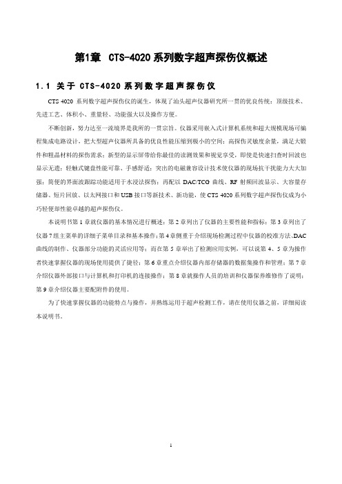
第1章CTS-4020系列数字超声探伤仪概述1.1关于C T S-4020系列数字超声探伤仪CTS-4020系列数字超声探伤仪的诞生,体现了汕头超声仪器研究所一贯的优良传统:顶级技术、先进工艺、体积小、重量轻、功能强大以及操作方便。
不断创新,努力达至一流境界是我所的一贯宗旨。
仪器采用嵌入式计算机系统和超大规模现场可编程集成电路设计,把大型超声仪器所具备的优良性能压缩到极小的空间;高探伤灵敏度余量,满足大锻件和粗晶材料的探伤需求;新型的显示屏带给你最佳的读测效果和视觉享受,即使是快速扫查时回波也显示无遗;轻触式键盘性能可靠、手感舒适;突出的电磁兼容设计技术使仪器的现场抗干扰能力大大加强;简便的界面波跟踪功能适用于水浸法探伤;再配以DAC/TCG曲线、RF射频回波显示、大容量存储器、短片回放、以太网接口和USB接口等新技术、新功能,使CTS-4020系列数字超声探伤仪成为小巧轻便却性能卓越的超声探伤仪。
本说明书第1章就仪器的基本情况进行概述;第2章列出了仪器的主要性能和指标;第3章列出了仪器7组主菜单的详细子菜单目录和基本操作;第4章侧重于介绍现场检测过程中仪器的校准方法、DAC 曲线的制作、仪器部分功能的灵活应用等;而在第5章举出了检测应用实例,可以说第4、5章为操作者快速掌握仪器的现场使用提供了捷径;第6章重点介绍仪器内部存储器的数据集操作和管理;第7章介绍仪器外部接口与计算机和打印机的连接操作;第8章就操作人员的培训和仪器保养维修作了说明;第9章介绍仪器主要配附件的使用。
为了快速掌握仪器的功能特点与操作,并熟练运用于超声检测工作,请在使用仪器之前,详细阅读本说明书。
1.2 仪器外观1.2.1 结构及接口LAN 以太网接口 电池后盖A :闸门报警指示灯 R :抑制功能指示灯 D :双探头工作方式指示灯仪器提手图1.2USB 接口探头接收/发射插座电源开关键上下调节键子菜单项选择按键组增益调节键特殊功能键主菜单按键组图1.1直流电源输入端1.2.2仪器画面子菜单显示区增益值读数增益步进波形区翻页(后翻)提示栏当前主菜单名测量数据区页数/总页数图1.31.2.3显示模式仪器屏幕显示分两种模式:●正常模式的A型扫描如图1.4所示,调节、设定仪器时使用这一显示模式:图1.4●放大模式的A型扫描如图1.5所示,现场探伤时可以选择这一显示模式:图1.5通过按缩放键激活放大模式。
cts-9009plus说明书

cts-9009plus说明书简单介绍:CTS-9009PLUS高空、野外作业数字超声探伤仪为新一代轻便型数字大功率探伤仪,是一种用途广泛、高性能、高稳定性和可靠性、功能强大的通用型探伤仪.整机(含电池)重量保持在1.15Kg,高空、野外作业轻松自如,分辨率高、穿透力强,满足从薄板到大铸件的探伤。
详情介绍:CTS-9009PLUS高空、野外作业数字超声探伤仪为新一代轻便型数字大功率探伤仪,是一种用途广泛、高性能、高稳定性和可靠性、功能强大的通用型探伤仪.整机(含电池)重量保持在1.15Kg,高空、野外作业轻松自如,分辨率高、穿透力强,满足从薄板到大铸件的探伤。
CTS-9009PLUS高空、野外作业数字超声探伤仪应用:应用领域:航天航空、电子机械、铁路行业、油田、造船及维修厂、钻井、轴承、铸造、汽车行业、化工行业、电力行业、冶金行业、锅炉压力容器行业、等内部多种缺陷如裂纹、焊缝未融合和未焊透、气孔、砂眼、夹杂、折叠等的检测、定位、定量和评价。
CTS-9009PLUS高空、野外作业数字超声探伤仪特点:-方波大功率发射穿透力强-宽频带高分辨率检出率高-网络视频传送远程控制-性能强劲:高压方波发射、穿透力强,满足大型铸、锻件探伤的需求-动态记录测厚内嵌标准-操作简易:按键少,定义明确,实现单手握持操作-防尘防水:按IP65防护标准设计,适应复杂的工业探伤环境-高采样速率240MHz,测量分辨率0.1mm-简便实用的探头频谱分析功能,快捷掌握探头的波形、频谱和中心频率,令探伤评价更准确-网络通信,实现探伤仪与计算机的实时双向通信和远程控制-外部U盘无限或内部3分钟动态记录功能,实现扫查过程全记录-测厚功能模块,具有多种测厚模式-超低功耗:标配锂聚合物电池,连续工作时间长达7小时-功能齐全:以太网通信、动态回放、探头频谱分析、曲面修正、USB转存、RF(射频)显示、AWSD1.1/D1.5、API 5UE评价标准-发射脉冲电压50~500V可调,发射脉冲为尖脉冲或方波,方波宽度51~850ns可调-工作频率范围0.5 ~ 20 MHz,灵敏度余量≥70 dB,分别突显宽频带和高灵敏度的优点-20 ~ 2000Hz的脉冲重复频率,步进20Hz,避免探伤过程中出现混响信号-RF(射频)回波功能,对于薄壁材料测量或学术研究和定性分析有很大帮助-端点反射法测量焊缝裂纹高度-内置AWS D1.1/D1.5、API 5UE评价标准-通过回波扩展功能可将闸门内回波区域放大到整个屏幕显示-自动增益控制AGC,配合峰值回波、图像冻结功能,快速确定缺陷*高波,探伤更高效-多种不同的显示颜色搭配方案,满足不同使用场景和习惯的需求-存储500组曲线及波形,满足不同探伤工艺应用及探伤数据存档的需求-AVG曲线,使用已知平底孔或大平底回波,制作出3条不同当量的曲线-DAC曲线,配合回波比较功能,使不同距离不同波幅的回波定量更简便CTS-9009PLUS高空、野外作业数字超声探伤仪数据编辑和管理探伤回波、曲线、参数等,可由以太网实时传输到计算机,或由USB接口经U盘将数据导入计算机,实现探伤报告的编辑和数据的管理动态记录外部U盘无限或内部3分钟外部U盘无限动态记录功能,实现扫查过程全记录探头频谱分析快捷掌握探头的波形、频谱和中心频率,令探伤评价更准确(图示为2.5Z20N探头频率图)焊缝检测模拟图;直接指出缺陷所在区域,位置一目了然(图示为厚度10mm平板焊缝缺陷位置)大锻件探伤;大探测范围,高灵敏度余量,满足大锻件或粗晶体材料的检测。
CTS5900罐旁指示仪产品手册by connetech V1.4

CTS 系列罐旁指示仪
北京锐达仪表有限公司
1
警告
静电防护措施
本仪表中由于含有易感受静电的电子器件。因此对其内部的电路板或元器件进行拆卸、以及安装等操作时, 均应采取适当有效的静电防护措施,并请按下述原则进行。
必须拆除仪表的供电电源 对印刷电路板或其内部元件进行接触、拆卸、安装、以及调整前,操作人员应佩戴防静电环或者采取其它安 全可靠的方式接地,确保静电快速顺畅的泄放。 印刷电路板必须置于导电包装袋或其它的导电容器中进行运输、存储,直到现场安装时,才允许将其从静电 防护包中取出。被拆换的印制电路板必须立即放进具有静电防护功能的容器内,不可随意放置以备运输、存储。
3
1 产品概述
1.1 产品功能
CTS 系列罐旁指示仪是应用在液体罐区数据显示和仪表远程操作的现场显示仪表。CTS 系列罐旁指示仪可以 通过现场总线与储罐上的液位测量仪表、温度测量仪表和压力测量仪表进行通讯,将仪表的测量数据读取下来并 且在罐旁指示仪上进行显示。同时罐旁指示仪又是一个信息采集设备,罐旁指示仪将现场仪表的数据通过数据总 线传输到中控室。
运输存储
仪表采用纸箱或木箱包装,在搬运时小心转运,不允许野蛮装,存放地点应符合防雨防潮、且不受机械震 动或冲击等。
开箱验货
仪表拆箱后严格按装箱清单验货,若发现有错误、缺货或破损等现象,请立即与我公司或当地代理联系。
CTS-9006,9008,9009_数字超声探伤仪中文说明书_A07_131030
菲克科技 CTS100 交叉滚柱导轨手动位移台 使用说明书
M16×P1.0深6
16×M4深5.7 20
100
27
25 25 50×50
70×70 90×90
4×M4用沉头孔
18.5
100
12.8
90×90
16×M4深5.7
M16×P1.0深6
20
100
25 25
50×50
70×70 90×90
12.8
100
18.5
27
90×90
4×M4用沉头孔
Tel :17302805818|
菲克科技
CTS100系列 交叉滚柱导轨手动位移台
CTS100 Cross-Roller Guide Manual Stages CTS100-(X) CTSXY100-(X) CTSXY100-(X)B
产品图纸D IMENSIONS
CTSXY100-C
M16×P1.0深6
16×M4深5.7
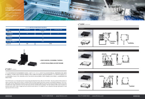
40
CTS100系列是菲克科技开发的超高精密手动位移台,台面尺寸100×100mm。该系列产品主体材料采用铝合金,表面阳极氧化处理,强度较 高 、耐 磨 性 好 、外 形 美 观 。采 用 交 叉 滚 柱 导 轨,精 密 微 分 头 驱 动,负 载 能 力 强,耐 用 性 好 。配 合 菲 克 科 技 精 密 加 工 工 艺,使 该 系 列 产 品 具 有 不 大 于 2μm的高灵敏度,并且运行平顺,无跳动现象。该系列产品主体材料为铝合金,质量轻,可内置于其他装置,适合对负载能力、运动精度等要求较高 的情况下使用。
产品参数SPECIFICATIONS
Model 行程(mm) 水平负载(kg) 位移方向 灵敏度(μm) 平行度(μm) 直线度(μm) 微分头最小读数(mm) 导轨 驱动方式 驱动位置 主体材料及表面处理 台面尺寸(mm) 厚度(mm) 自重(kg)
- 1、下载文档前请自行甄别文档内容的完整性,平台不提供额外的编辑、内容补充、找答案等附加服务。
- 2、"仅部分预览"的文档,不可在线预览部分如存在完整性等问题,可反馈申请退款(可完整预览的文档不适用该条件!)。
- 3、如文档侵犯您的权益,请联系客服反馈,我们会尽快为您处理(人工客服工作时间:9:00-18:30)。
目 录1. 功能简介 (1)2. 硬件认识与配置 (1)2.1 电池仓 (1)2.2 CTS电池接口介绍 (2)2.3 电池正负极及SC、SD引脚的判断 (3)2.4 电池与CTS的连接 (3)2.5 CTS箱号及GGS-ID (4)2.6通讯口介绍 (5)3. 联机设置 (6)3.1 COM口的设置 (6)4. CTS与GGS指示信号的识别 (7)4.2 信号识别 (7)5. 软件介绍与基本操作 (8)5.1 各快捷功能介绍 (8)5.2 工作模式及各参数、条件介绍 (8)5.2.1 静置 ST (8)5.2.2 恒流充电 (8)5.2.3 恒压充电 (9)5.2.4 恒流放电DC (9)5.2.5 恒功率放电CP: (9)5.2.6 COMMAND (9)5.2.7 跳转(GOTO) (9)5.2.8 停止 (9)5.3 正常判断条件(To Next Step) (10)5.3.1 结束时间 (10)5.3.2 结束电压 (10)5.3.3 结束电流 (10)5.3.4 结束容量 (10)5.3.5 RSOC (10)5.3.6 -△V: (10)5.4 例外限制条件(Stop) (11)5.4.1 电流台阶 (11)5.4.2 最小容量 (11)5.4.3 最大容量 (12)5.4.4 △DCR (12)5.5 安全保护 (12)5.5.1 电压设置 (12)5.5.2 电流范围± (12)5.6 数据记录条件 (13)5.7 启动电池进行充放电 (13)5.7.1 修改CTS箱号及GGS—ID (13)5.7.2 联机 (13)5.7.3启动电池 (14)5.8 制程(tpl)文件的保存 (16)5.9 更改通道工作模式 (18)5.10 启动后通道的版面信息 (18)6. 数据查看及图形分析 (19)6.1 图形数据的打开 (19)6.2 图形数据的查看技巧 (20)6.2.1 数据折叠 (20)6.2.2 时间单位设置 (20)6.2.4 查看测试日志 (22)6.2.5 数据另存为 (22)6.2.6 生成EXCEL文件格式文件 (23)6.2.7 图形查看与设置 (23)6.2.8 输出图形文件 (24)6.2.9 图形分析 (24)7. GGS的认识与使用 (26)7.1 联机 (26)7.2 读取电池的Gas Gauge数据 (27)7.3 电池信息比对 (27)CTS 使用说明书1. 功能简介主要应用于电池包生产中的寿命老化测试(Circle Life Testing),和智能电池数据训练(Circle Learning)以及质量控制。
2. 硬件认识与配置本公司生产的充放电机台硬件部分为模块化设计,每8个独立信道为一个模块。
一般每台机柜由40个独立通道构成,实物如图2-1所示。
图2-1 电池测试系统 CTS2.1 电池仓由图可知,每台机柜由5台相互独立工作的CTS和对应的电池仓组成。
电池仓的构成如图2-2所示。
图2-2 电池仓构成我们的电池仓由2mm厚的钢板组成,在整个系统中既起到了方便测试又具有保证测试安全的双重功效。
与此同时我们在电池仓内铺设有由阻燃抗静电PVC 材料制作的塑料托盘如图2-3所示。
塑料托盘上还铺设了一层由硅胶制成的天然无污染的防滑垫如图2-4所示,它能很好的保证我们的电池在电池仓在开关的过程中,不至与连接器脱落。
图2-3 黑色阻燃抗静电塑料托盘 图2-4 硅胶防滑垫2.2 CTS电池接口介绍与智能电池连接的接口如图2-5所示。
各管脚从左至右分别为:V+、I+、I+、C、D、I-、I-、V-。
在实际使用当中我们需要将V+、I+,I-、V-分别短接起来并对应连接到到电池的正和负。
C、D分别代表SMbus的SMC和SMD。
在与电池连接时对应连接到电池的SC、SD端。
图2-5 设备接口定义2.3 电池正负极及SC、SD引脚的判断首先我们可以通过万用表很方便的测试出电池的正负极,然后将数字万用表调到二极管档,将红表笔接到电池的负极并用黑表笔去接电池的其它引脚(一般电池的引脚个数都会大于4个)当万用表有零点几伏的管压降时即为电池的SC 和SD引脚。
根据智能电池制作时默认将SC引脚靠近电池正极,而将SD引脚靠近电源负极。
这样我们就可以通过这个默认制作规定将SC和SD引脚区分开来。
2.4 电池与CTS的连接在介绍CTS电池接口的时候,我们提到将电池接到CTS设备时需要将CTS 端口的V+、I+,I-、V-分别短接起来。
而我们的设备为了在出厂前更好的对其进行调试我们没有将其短接。
为了解决这个问题,我们需要在外部将它们短接起来。
此处我们采用在连接电池和CTS的导线上将其短接起来的办法。
我们将用于连接电池与CTS得导线制作成如图2-6所示。
图2-6特制连接电池的导线 图2-7 通用连接器在将电池与导线相连接时,需要使用由瑞能公司提供的如图2-7所示的专用连接器。
该连接器具有很强的通用性。
连接器与电池的连接如图2-8所示。
在将电池与连接器相连时,一定要注意将电池的正极负、极连SC、SD四个引脚依次与CTS设备对接起来。
这对保证充放电及智能电池与设备的正常通讯起着至关重要的作用。
我们的设备提供电池反接保护和反接提醒功能。
当电池接反时,设备的通道LED将出现闪烁。
如图2-9所示为电池与CTS设备完整连接图。
图2-8 连接器与电池的连接图图2-9 电池与设备的连接2.5 CTS箱号及GGS-ID在我们的设备中,不同的CTS机台及GGS都有各不相同的箱号。
不同的箱号在多台设备通信中起着十分重要的作用。
如图2-8所示即为显示CTS箱号及GGS-ID的数码管。
图2-8 CTS箱号及GGS-ID2.6通讯口介绍我们的设备采用R/S 232模式,通讯线路在机台的背面,如图2-9所示。
如图我们可以看到我们的设备含有两个串行通讯口——CTS通讯口和GGS通讯口(不含GGS的设备没有GGS通信口)。
图2-9 设备通讯口值得注意的是我们的设备如果是单台的它就不带CM功能,若多台连接使用则必须使用带CM功能的通讯口。
实际使用中,不带CM功能的设备可以直接与计算机相连。
而带CM功能的设备不能直接与计算机相连否则会损坏计算机的串口。
它们之间的连接需要由瑞能公司提供的如图2-10所示的隔离盒实现。
通过隔离盒连接到计算机上还能够系统通信的抗干扰能力。
整个通信连接线路如图2-11所示。
图2-10 隔离盒图2-11 通信线路连接图3. 联机设置对于我们公司生产的CTS设备,每台计算机能够有效控制480个测试通道,增配多串口卡,可以实现多进程控制。
多串口多个程序进程控制时,必须注意以下事项:a.需要更改每个软件的名称,以免注册表重迭。
b.同一台计算机控制的CTS不能有相同的箱号box ID,以免停电恢复时造成数据出错。
3.1 COM口的设置初次使用软件时需要对软件通讯COM端口进行设置。
对COM口的更改受管理权限的控制。
如图3-1我们首先打开我们的CTS软件,选择“管理”菜单下的“管理登陆”命令,进入如图3-2所示“Login”对话框。
输入密码后即可完成管理登陆。
管理密码默认为admin,用户可以根据需要作出相应的修改。
图3-1 选择管理登陆命令图3-2 Login 对话框管理登陆后,我们选择CTS软件“选项”菜单下的“优化自动联机”命令,打开如图3-3所示“优化自动联机”对话框。
在箱号命令栏中,“从”下拉菜单中选择从001,“到”下拉菜单中选择我们计算机连接的设备的最大箱号。
在串行口命令栏中,“从”下拉菜单中选择从COM1,“到”下拉菜单中选择我们计算机连接设备时的最大串口号。
实际使用中我们可以将范围设置得比我们的使用范围略大一些。
图3-3优化自动联机对话框4. CTS与GGS指示信号的识别4.1 CTS信号的识别上电后,CTS设备有一个自检的过程,接口处的LED将从通道1至通道8依 次点亮,最后全部熄灭。
在智能电池进行充放电的过程中,如若发现接口处的LED出现闪烁的情况,则说明电池在充放电的过程中出现了异常。
出现异常的原因以及清除闪烁的方法将在后面的内容进行讲解。
4.2 信号识别当智能电池正确接入CTS设备时,如图4-1所示通道指示灯亮。
它表示智能电池与设备间能够正常通信。
图4-1 通信正常指示灯5. 软件介绍与基本操作5.1 各快捷功能介绍打开软件后,我们可以看见在左侧有一个快捷功能工具栏,如图5-1所示。
图5-1 快捷功能工具栏从左至右它们的含义分别是:1.打开当前数据文件夹,可查询当前测试数据。
2.编辑测试制程,用于编辑充放电的流程及参数的设定。
3.查看窗口,显示每个通道当前工作状态。
4.Flash LED:用于准确定位查询通道。
5.Clear LED:清除所有通道报警闪烁中的LED。
6.查询软件连接状况。
7.更改数据存放路径。
5.2 工作模式及各参数、条件介绍在本设备下,智能电池进行老化和智能数据学习时,可以有多种工作模式。
现将各工作模式及其参数1、参数2的设置介绍如下:5.2.1 静置ST电流回路处于切断状态,但不停地电压信息的采集。
主要要设置的参数为静置时间(结束时间)。
5.2.2 恒流充电参数1设置恒流充电电流大小,一般为电池设计容量的一半。
参数2设置为恒压充电电压大小,一般设置为电池的满充电压。
例如3串锂电池设置为12.6V,4串设置为16.8V。
注:我们的设备在进行充电的过程中分为CC(恒流)和CV(恒压)两个过程。
在充电伊始保持充电电流为参数1设定的恒定值,当电池电压达到参数2设置的电压值时,保持电压值不变而电流值不断地减小,形成一个涓流充电的过程。
整个过程中CC占据大约70%的时间,CV的过程大约为30%的时间。
5.2.3 恒压充电参数1与参数2的设定与恒流充电的一致。
在我们的软件当中,恒压与恒流充电执行的过程完全相同,用户只用选择其中的一种即可。
5.2.4 恒流放电DC恒流放电时,我们只需要且只能设置参数1。
我们设置参数1为用户需要的放电电流大小,一般为电池设计容量的一半。
5.2.5 恒功率放电CP:恒定功率放电模式。
采用硬件乘法器的恒功率算法。
参数1设置为放电功率。
5.2.6 COMMAND命令加载模式,用于智能电池充放电前或充放电结束后为电池加载命令或写入数据。
5.2.7 跳转(GOTO)设置参数1为要跳转到制程的第几步。
结束时间设置跳转的次数。
跳转的设置一般用在对智能电池反复充放电进行老化学习的制程中。
5.2.8 停止通道彻底进入停止状态,智能电池的回路从充放电机完全断开。
此工作模式下用户不需要设置任何参数。
5.3 正常判断条件(To Next Step)5.3.1 结束时间限制对电池的充放电时间。
5.3.2 结束电压限制充放电结束电压(实际使用中我们一般用来设置放电结束电压)。