WP1503EB-2GD中文资料
常用三极管参数大全
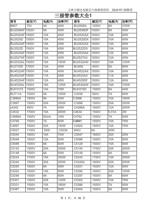
玉林万顺达电脑芯片级维修资料 2010-07-20整理玉林万顺达电脑芯片级维修资料 2010-07-20整理玉林万顺达电脑芯片级维修资料 2010-07-20整理玉林万顺达电脑芯片级维修资料 2010-07-20整理玉林万顺达电脑芯片级维修资料 2010-07-20整理玉林万顺达电脑芯片级维修资料 2010-07-20整理玉林万顺达电脑芯片级维修资料 2010-07-20整理玉林万顺达电脑芯片级维修资料 2010-07-20整理玉林万顺达电脑芯片级维修资料 2010-07-20整理玉林万顺达电脑芯片级维修资料 2010-07-20整理玉林万顺达电脑芯片级维修资料 2010-07-20整理玉林万顺达电脑芯片级维修资料 2010-07-20整理玉林万顺达电脑芯片级维修资料 2010-07-20整理玉林万顺达电脑芯片级维修资料 2010-07-20整理玉林万顺达电脑芯片级维修资料 2010-07-20整理玉林万顺达电脑芯片级维修资料 2010-07-20整理玉林万顺达电脑芯片级维修资料 2010-07-20整理玉林万顺达电脑芯片级维修资料 2010-07-20整理玉林万顺达电脑芯片级维修资料 2010-07-20整理玉林万顺达电脑芯片级维修资料 2010-07-20整理玉林万顺达电脑芯片级维修资料 2010-07-20整理玉林万顺达电脑芯片级维修资料 2010-07-20整理玉林万顺达电脑芯片级维修资料 2010-07-20整理玉林万顺达电脑芯片级维修资料 2010-07-20整理玉林万顺达电脑芯片级维修资料 2010-07-20整理玉林万顺达电脑芯片级维修资料 2010-07-20整理玉林万顺达电脑芯片级维修资料 2010-07-20整理玉林万顺达电脑芯片级维修资料 2010-07-20整理玉林万顺达电脑芯片级维修资料 2010-07-20整理玉林万顺达电脑芯片级维修资料 2010-07-20整理。
联想(北京)有限公司认证产品名称、型号规格表一
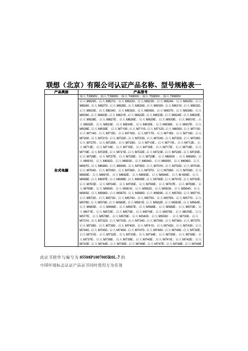
联想(北京)有限公司认证产品名称、型号规格表一产品类别 产品型号扬天T2900V、扬天T3900V、扬天T4900V、扬天T5900V、扬天T6900V台式电脑启天M8200、启天M8210、启天M8220、启天M8230、启天M8240、启天M8250、启天M8260、启天M8270、启天M8280、启天M8290、启天M8300、启天M8310、启天M8320、启天M8330、启天M8340、启天M8350、启天M8360、启天M8370、启天M8380、启天M8390、启天M820E、启天M821E、启天M822E、启天M823E、启天M824E、启天M825E、启天M826E、启天M827E、启天M828E、启天M829E、启天M830E、启天M831E、启天M832E、启天M833E、启天M834E、启天M835E、启天M836E、启天M837E、启天M838E、启天M839E 启天M7100、启天M7110、启天M7120、启天M6000、启天M7130、启天M7140、启天M7150、启天M7160、启天M7170、启天M7180、启天M7190、启天M7200、启天M7210、启天M7220、启天M7230、启天M7240、启天M7250、启天M7260、启天M7270、启天M7280、启天M7290、启天M710E、启天M711E、启天M712E、启天M713E、启天M714E、启天M715E、启天M716E、启天M717E、启天M718E、启天M719E、启天M720E、启天M721E、启天M722E、启天M723E、启天M724E、启天M725E、启天M726E、启天M727E、启天M728E、启天M729E、启天M6000 、启天M6900、启天M6910、启天M6920、启天M6930、启天M6940、启天M6950、启天M6960、启天M6970、启天M6980、启天M6990、启天M7000、启天M7010、启天M7020、启天M7030、启天M7040、启天M7050、启天M7060、启天M7070、启天M7080、启天M7090、启天M690E、启天M691E、启天M692E、启天M693E、启天M694E、启天M 695E、启天M696E、启天M697E、启天M698E、启天M699E、启天M700E、启天M701E、启天M702E、启天M703E、启天M704E、启天M705E、启天M706E、启天M707E、启天M708E、启天M709E、启天M5600、启天M5610、启天M5620、启天M5630、启天M5640、启天M5650、启天M5660、启天M5670、启天M5680、启天M5690、启天M5700、启天M5710、启天M5720、启天M5730、启天M5740、启天M5750、启天M5760、启天M5770、启天M5780、启天M5790、启天M560E、启天M561E、启天M562E、启天M563E、启天M564E、启天M565E、启天M566E、启天M567E、启天M568E、启天M569E、启天M570E、启天M571E、启天M572E、启天M573E、启天M574E、启天M575E、启天M576E、启天M577E、启天M578E、启天M579E、启天M3400、启天M5500 、启天M7300、启天M7310、启天M7320、启天M7330、启天M7340、启天M7350、启天M7360、启天M7370、启天M7380、启天M7390、启天M7400、启天M7410、启天M7420、启天M7430、启天M7440、启天M7450、启天M7460、启天M7470、启天M7480、启天M7490、启天M730E、启天M731E、启天M732E、启天M733E、启天M734E、启天M735E、启天M736E、启天M737E、启天M738E、启天M739E、启天M740E、启天M741E、启天M742E、启天M743E、启天M744E、启天M745E、启天M746E、启天M747E、启天M748E、启天M749E此证书附件与编号为05508P1007005R0L-7的中国环境标志认证产品证书同时使用方为有效联想(北京)有限公司认证产品名称、型号规格表二产品类别 产品型号扬天A8800K、扬天A8000K、扬天A6800K、扬天A6000K、扬天A4600K、扬天A2600K,扬天A5700K、扬天A7700K扬天 T2900D、扬天 T3900D、扬天 T4900D、扬天 T5900D、扬天 T6900D 台式电脑ThinkCentre M9000z、 ThinkCentre M9010z、 ThinkCentre M9020z、 ThinkCentreM9030z、 ThinkCentre M9040z、ThinkCentre M9050z、 ThinkCentre M9060z、ThinkCentre M9070z、 ThinkCentre M9080z、 ThinkCentre M9090zLenovo IdeaPad U160、Lenovo IdeaPad U165、Lenovo G460、Lenovo G460A、LenovoG460AL、Lenovo G460AX、Lenovo G460AP、Lenovo G460AE、Lenovo G460AM、LenovoG460AK、Lenovo G460AN、Lenovo G460AS、Lenovo G460AT、Lenovo G460G、LenovoG460L、Lenovo G460GX、Lenovo G460LX、Lenovo G460LP、Lenovo G560、LenovoG465、Lenovo G465A、Lenovo G465AX、Lenovo G465AP、Lenovo G465G、LenovoG465GX、Lenovo G465GP、Lenovo G565、Lenovo G565A、Lenovo G565AX、LenovoG565G、Lenovo G565GX、Lenovo IdeaPad Z460、Lenovo IdeaPad Z460G、LenovoIdeaPad Z460GX、Lenovo IdeaPad Z460A、Lenovo IdeaPad Z460AX、Lenovo IdeaPadZ460AL、Lenovo IdeaPad Z460AC、Lenovo IdeaPad Z460AH、Lenovo IdeaPad Z460AM、Lenovo IdeaPad Z460AE、Lenovo IdeaPad Z460AK、Lenovo IdeaPad Z460AN、LenovoIdeaPad Z460L、Lenovo IdeaPad Z460LM、Lenovo IdeaPad Z460LE、Lenovo IdeaPadZ460LK、Lenovo IdeaPad Z460LN、Lenovo IdeaPad Z460LX、Lenovo IdeaPad Z560、笔记本电脑Lenovo IdeaPad Z560G、Lenovo IdeaPad Z560GX、Lenovo IdeaPad Z560A、LenovoIdeaPad Z560AX、Lenovo IdeaPad Z560AH、Lenovo IdeaPad Z465、Lenovo IdeaPadZ465G、Lenovo IdeaPad Z465GX、Lenovo IdeaPad Z465A、Lenovo IdeaPad Z465AL、Lenovo IdeaPad Z465AX、Lenovo IdeaPad Z465AM、Lenovo IdeaPad Z465AE、LenovoIdeaPad Z465AK、Lenovo IdeaPad Z465AN、Lenovo IdeaPad Z565、Lenovo IdeaPadZ565G、Lenovo IdeaPad Z565GX、Lenovo IdeaPad Z565A、Lenovo IdeaPad Z565AXLenovo 3000 G550、Lenovo G550、Lenovo G555、Lenovo G555A、Lenovo G555AX、Lenovo B550Lenovo 3000 G450、Lenovo 3000 G450L、Lenovo 3000 G450A、Lenovo 3000 G450M、Lenovo G450、 Lenovo G450AX、 Lenovo G450LX、 Lenovo G450A、Lenovo G450AP、Lenovo G455、Lenovo G455A、 Lenovo G455AX、Lenovo G455AP、Lenovo G455G、Lenovo G455GX此证书附件与编号为05508P1007005R0L-7的中国环境标志认证产品证书同时使用方为有效联想(北京)有限公司认证产品名称、型号规格表三产品类别 产品型号笔记本电脑Lenovo IdeaPad Y460、Lenovo IdeaPad Y460A、Lenovo IdeaPad Y460N、Lenovo IdeaPad Y460C、Lenovo IdeaPad Y460AT、Lenovo IdeaPad Y460AM、Lenovo IdeaPad Y460AE、Lenovo IdeaPad Y460AK、Lenovo IdeaPad Y460AN、Lenovo IdeaPad Y460NM、Lenovo IdeaPad Y460NE、Lenovo IdeaPad Y460NK、Lenovo IdeaPad Y460NN、Lenovo IdeaPad Y460CM、Lenovo IdeaPad Y460CE、Lenovo IdeaPad Y460CK、Lenovo IdeaPad Y460CN、Lenovo IdeaPad Y560、Lenovo IdeaPad Y560d、 Lenovo IdeaPad Y560A、Lenovo IdeaPad Y560AT、Lenovo IdeaPad Y560D、 Lenovo IdeaPad Y560DT、 Lenovo IdeaPad Y560C此证书附件与编号为05508P1007005R0L-7的中国环境标志认证产品证书同时使用方为有效。
腾达 W150M 用户手册
版 权 申 明是深圳市吉祥腾达科技有限公司注册商标。
文中提及到的其它商标或商品名称均是他们所属公司的商标或注册商标。
本产品的所有部分,包括配件和软件,其版权属深圳市吉祥腾达科技有限公司所有,在未经过深圳市吉祥腾达科技有限公司许可的情况下,不得任意拷贝、抄袭、仿制或翻译成其它语言。
本手册中的所有图片和产品规格参数仅供参考,随着软件或硬件的升级会略有差异,如有变更,恕不另行通知,如需了解更多产品信息,请浏览我们的网站:目 录第1章产品简介 (1)1.1产品规格 (2)1.2包装清单 (2)1.3面板指示灯及接口说明 (3)第2章产品硬件安装 (5)2.1硬件安装 (5)第3章工作模式介绍 (7)3.1无线接入点模式(AP模式) (7)3.2客户端+覆盖模式(C LIENT+AP模式) (8)3.3桥接+覆盖模式(WDS+AP模式) (8)3.4无线信号放大模式(WISP模式) (9)3.5无线路由器模式(W IRELESS R OUTER模式) (10)第4章如何登录到设备 (11)4.1正确设置您的计算机网络配置 (11)4.2登陆 (13)第5章工作模式设置 (14)5.1无线接入点模式设置向导 (14)5.2无线客户端+覆盖模式设置向导 (15)5.3无线桥接+覆盖模式设置向导 (18)5.4无线信号放大模式设置向导 (21)5.5无线路由器模式设置向导 (24)第6章高级设置 (30)6.1LAN设置 (30)6.2WAN设置 (31)6.3WAN口参数 (33)6.4MAC地址克隆 (33)6.5域名服务器 (34)第7章无线设置 (36)7.1基本设置 (36)7.2无线安全设置 (37)7.3高级设置 (40)7.4WPS设置 (41)7.5无线访问控制 (43)7.6连接状态 (44)第8章 DHCP服务器 (45)8.1DHCP服务设置 (45)8.2DHCP列表与绑定 (46)第9章虚拟服务器 (47)9.1端口段映射 (47)9.2DMZ主机 (48)9.3UPNP设置 (49)第10章安全设置 (50)10.1客户端过滤 (50)10.2URL过滤 (51)10.3MAC地址过滤 (52)10.4防网络攻击 (54)10.5远程WEB管理 (54)10.6WAN口PING (55)第11章路由设置 (56)11.1路由表 (56)第12章系统工具 (57)12.1时间设置 (57)12.2DDNS (57)12.3备份/恢复设置 (59)12.4恢复出厂设置 (60)12.5软件升级 (61)12.6重启设备 (61)12.7修改登录密码 (62)12.8系统日志 (62)12.9退出登录 (63)附录一:如何将电脑的IP地址改成自动获取? (64)附录二:设备加密后如何设置,能让无线网卡成功连接到本设备? (67)附录三:名词解释 (69)附录四:常见问题解答 (71)第1章产品简介感谢您购买W150M便携式无线AP/路由器(以下简称设备)W150M是一款便携式无线AP/设备,W150M无线传输速率为150Mbps,它具有五种功能实现各种无线应用。
康佳产品培训手册
3G的典型应用
3G手机,掌中无 线宽带,更快更强 大
本资料仅供内部参考,请勿用于传播
3G就是随身携带的ADSL
1. 3G无线网络游戏 2. 3G无线高速搜索 3. 3G无线高速下载 4. 3G在线电影电视 5. 3G无线网络电视机 6. 3G超流畅视频通话 7. 3G高品质在线音乐/下载音乐 8. 3G无线……
本资料仅供内部参考,请勿用于传播
产品传播
公关传播——传播主旋律 康佳领驭系列 精英人士之选 W371准3G体验手机
传播思路分析——核心传播点 康佳领驭W371极速准3G体验手机,超3G体验的网络手机,带 您进入互联网新时代!
本资料仅供内部参考,请勿用于传播
一、准3G手机解译
本资料仅供内部参考,请勿用于传播
2G EDGE
√
3G TD_SCDMA √
3G TD_SCDMA √
3G TD_SCDMA √
都是在144kps- 384kps之间。
夏新
T5 3G TD_SCDMA √
多普达 S700 3G TD_SCDMA √
康佳W371使用的是GSM的EDGE网络,网络覆 Haier HT-T300 3G TD_SCDMA √
硬件
屏幕
WQVGA 16:9宽阔显示 真正物理纯平显示屏 全新一代触摸感应屏
康佳领驭
W371
可视通话、JAVA扩展、加速度动感游戏 WWW上网、多种专业股票软件、IPTV 丰富多媒体功能,流畅视频播放。。。
软件
本资料仅供内部参考,请勿用于传播
目标消费者洞察
26岁~45岁
他们注重生活品质、关注新讯, 他们是意见领袖,走在最前线。
准3G手机解译
第一部分:等同3G
中频逆变直流电阻焊机同其他电阻焊机之比较
中频逆变直流电阻焊机同其他电阻焊机之比较等世界各厂提供的原材料配套,性能稳定,质量可靠。
我们致力于研究开发不同材质的焊接工艺,务求客户在焊接工艺中尽善尽美。
深圳市福威特焊机有限公司实力雄厚,重信用、守合同、保证产品质量,以多品种经营特色和薄利多销的原则,赢得了广大客户的信任。
公司一贯坚持“质量第一,用户至上,优质服务,信守合同”的宗旨,凭借着高质量的产品,良好的信誉,优质的服务,产品畅销全国近三十多个省、市、自治区以及远销欧美、意大利等国家。
竭诚与国内外商家双赢合作,共同发展,共创辉煌!中频逆变点焊机型号:FWT-20000机器图片展示:产品描述:◆每分钟最高可输出焊点1500个;◆1KHZ、2KHZ、4Khz、8kHz、10KHZ、20KHZ逆变频率,控制精度高,焊接时间可以精确到0.25毫秒或0.125毫秒;◆LCD显示直观,触摸液晶显示屏,操作方便;◆恒定电流、恒定电压、恒定功率、定脉宽等控制方式,适合多种材料多种产品焊接;◆三段放电加热方式,电流缓升缓降控制;◆设定参数上、下限电流监控;中频逆变电阻点焊机特点:1、电流直流输出,焊接电流为脉动直流(且波纹度小);2、IGBT逆变频率1~8KHZ,通电时间控制周期为0.125ms,放电时间可任意调节控制;3、可实时监控电流、电压、功率;4、具有电流失常、监控值超限、网压超限、过热等故障诊断与报警功能;可极大减少产品焊接不良率。
5、三段放电设定,带电流缓升缓降功能,可有效解决“飞溅”,更加保证了焊接的稳定性。
6、电极寿命能有效延长。
节能50%以上。
适用范围:广泛应用于铜、镍、不锈刚等有色金属和电子器件、精密仪表、低压电器及轻工、家电等行业。
中频逆变直流电阻焊机同其他电阻焊机之比较中频逆变直流电阻焊机优势一、目前国际最先进的电阻焊产品二、具有无可比拟的焊接稳定性;三、低运行成本:1.三相电源平衡输入,功率因数高达95%。
2.次级回路几乎没有感应能量损失。
网驰350升级版销售指导

接口类型
网孔升级
现生产的网驰350升级版蜂窝状散热孔已 经升级为大网孔,散热型能更好。
12CM静音风扇
产品铭牌
鑫谷电源网驰350升级版销售指导
产品特点
1、 采用最新ATX12V 2.3版本设计,额定220W,为广大的 入门级DIY用户提供强大动力支持。 2、 +12V输出电流加强至15A,为3D游戏平台提供强大动 力支持。 3、 采用12CM静音大风扇,散热更好,噪音更低。 4、 内建节能PFC电路全面提高电能的使用效率。 5、 内建过压、过流、欠压、短路、过热、过载保护技术。 6、 提供1条S-ATA高速串口硬盘电源输出接口。 采用(20+4)PIN+4PIN输出接口
维沙耶芯片电阻说明书
Document Number: 28744For technical questions, contact: *************************** MCS 0402 VG01, MCT 0603 VG01, MCU 0805 VG01 andMCA 1206 VG01 thin film flat chip resistors with establishedreliability are the perfect choice for all high-reliabilityapplications typically found in military, aircraft and spacecraftelectronics. These versions supplement the families ofprofessional and precision thin film flat chip resistorsMCS 0402, MCT 0603, MCU 0805 and MCA 1206.∙Established reliability, failure rate level E6∙Advanced thin film technology ∙Pure Sn termination on Ni barrier layer ∙Single lot date code ∙Material categorization: For definitions of complianceplease see /doc?99912APPLICATIONS∙Military ∙Avionics ∙Space Notes•These resistors do not feature a limited lifetime when operated within the permissible limits. However, resistance value drift increasing over operating time may result in exceeding a limit acceptable to the specific application, thereby establishing a functional lifetime.•The failure rate level E6 (10-6/h, πQ = 0.3), corresponding to MIL Level P, is superior to level E5 (10-5/h, πQ = 1) and thus may be used as areplacement.METRIC SIZE IMPERIAL0402060308051206EN/CECC RR1005M RR1608M RR2012M RR3216M TECHNICAL SPECIFICATIONSDESCRIPTIONMCS 0402 VG01MCT 0603 VG01MCU 0805 VG01MCA 1206 VG01EN/CECC style (size)RR1005M RR1608M RR2012M RR3216MResistance range10 Ωto 1 M Ω; 0Ω 1 Ωto 1 M Ω; 0ΩResistance tolerance± 1 %; ± 0.1 %T emperature coefficient± 50ppm/K; ± 15 ppm/K Rated dissipation, P 700.063W 0.1W 0.125W 0.25W Operating voltage, U max. AC/DC50V 75 V 150V 200V Permissible film temperature, ϑF max.125︒C Operating temperature range- 55 °C to 125 °C Max. resistance change at P 70for resistance range, |∆R /R| max. after:10 Ωto 1 M Ω 1 Ωto 1 M Ω1000h≤ 0.25 %8000h≤ 0.5 %225000h≤ 1.5 %Permissible voltage against ambient(insulation):1 min; U ins75V 100V 200V 300V Continuous75V 75V 75V 75V Assessed failure rate levelE6 = 10-6/h Quality factor, πQ0.3Failure rate: FIT observed < 0.1 x 10⁻⁹/h For technical questions, contact: ***************************Document Number: 28744Notes•The products can be ordered using either the PART NUMBER or the PRODUCT DESCRIPTION.•Products within a packaging unit are single lot date code.TYPE/SIZEVERSION TCR RESISTANCE TOLERANCE PACKAGING MCS 0402MCT 0603MCU 0805MCA 1206H = EN 140401-801,“Version E”;failure rate level E6 C = ± 50 ppm/K E = ± 15 ppm/K Z = Jumper 3 digit value 1 digit multiplier MULTIPLIER8 = *10-29 = *10-10 = *1001 = *1012 = *1023 = *1034 = *1040000 = Jumper F = ± 1 %B = ± 0.1 %Z = JumperE1E0P1P5Product Description: MCT 0603-50 1% VG01 P5 287KProduct Description: MCT 0603 VG01 P5 0R0MCT 0603-50 1 %VG01P5287K MCT 0603--VG01P50R0TYPE/SIZETCR T OLERANCE VERSION PACKAGING RESISTANCE MCS 0402MCT 0603MCU 0805MCA 1206± 50 ppm/K ± 15 ppm/K ± 1 %± 0.1 %VG01 = EN 140401-801,“Version E”;failure rate level E6E1E0P1P549R9 = 49.9 Ω287K = 287 k Ω0R0 = JumperMC T 0603H Z 0000Z P 50006032873500Document Number: 28744For technical questions, contact: *************************** Note•The ordering information according to EN 140401-801:2007 shown above succeeds and replaces the ordering information according to earlier versions of the detail specification EN 140401-801 or its predecessor CECC 40401-801, for example:CECC 40401-801 EZ RR1608M C 287K F E6CECC 40401-801 S RR1608M C 287K F E6with EZ; S Assessment level, where EZ is successor to and superior replacement for SRR1608M Style, with suffix M for “metric”C Temperature coefficient, according to the detail specificationC = ± 50 ppm/K; E = ± 15 ppm/K Note•According to EN 140401-801, resistance values are to be selected from the E96 series for ±1% tolerance and from the E192 series for ±0.1 % tolerance.EN140401-801EZRR1608M-0R00-E6The elements used in the component number have the following meaning:EN140401-801EZRR1608MR287KF E6EN detail specification number Assessment level for the zero-defect approach Style (size)T emperature coefficient, according to EN 60062R = ± 50 ppm/K; P = ± 15 ppm/K Resistance, according to EN 60062, 4 characters T olerance on rated resistance, according to EN 60062F = ± 1 %; B = ± 0.1 %Failure rate level according to EN 60115-1, annex ZRTEMPERATURE COEFFICIENT AND RESISTANCE RANGEDESCRIPTIONRESISTANCE TCRTOLERANCE MCS 0402 VG01MCT 0603 VG01MCU 0805 VG01MCA 1206 VG01± 50 ppm/K± 1 %10 Ωto 1 M Ω 1 Ωto 1 M Ω1Ωto 1 M Ω1Ωto 1 M Ω± 15 ppm/K± 0.1 %100Ωto 33.2 k Ω100Ωto 47.5 k Ω100Ωto 100k Ω43.2Ωto 332k ΩJumper ≤ 20m Ω; I max. = 0.63 A ≤ 20m Ω; I max. = 1 A ≤ 20m Ω; I max. = 1.5 A≤ 20m Ω; I max. = 2 A PACKAGINGTYPECODE QUANTITY CARRIER TAPE WIDTH PITCH REEL DIAMETER MCS 0402 VG01E11000Paper tape acc. IEC 60286-3T ype I 8 mm 2 mm 180 mm/7"E010 000MCT 0603 VG01P110008 mm 4 mm P55000MCU 0805 VG01P11000P55000MCA 1206 VG01P11000P55000 For technical questions, contact: ***************************Document Number: 28744Note•Resistors MCA 1206 VG01 and MCU 0805 VG01 are marked using to the four-character code system of IEC 60062, 4.2.3.Resistors MCT 0603 VG01 and MCS 0402 VG01 do not show any marking on their light blue protective coating.Note•The given solder pad dimensions reflect the considerations for board design and assembly as outlined e.g. in standards IEC 61188-5-x, or in publication IPC 7351. They do not guarantee any supposed thermal properties, however, they will be found adequate for most general applications.DIMENSIONS AND MASSTYPEH (mm)L (mm)W (mm)W T (mm)T b (mm)T t (mm)MASS (mg)MCS 0402 VG010.32 ± 0.05 1.0 ± 0.050.5 ± 0.05> 75 % of W 0.2 ± 0.10.2 + 0.1/- 0.150.6MCT 0603 VG010.45 + 0.1/- 0.05 1.55 ± 0.050.85 ± 0.10.3 + 0.15/- 0.21.9MCU 0805 VG010.45 + 0.1/- 0.052.0 ± 0.11.25 ± 0.150.4 + 0.1/- 0.2 4.6MCA 1206 VG010.55 ± 0.1 3.2 + 0.1/- 0.2 1.6 ± 0.150.5 ± 0.259.2RECOMMENDED SOLDER PAD DIMENSIONSTYPE WAVE SOLDERINGREFLOW SOLDERING G(mm)Y (mm)X (mm)Z (mm)G (mm)Y (mm)X (mm)Z(mm)MCS 0402 VG01----0.350.550.55 1.45MCT 0603 VG010.551.10 1.102.750.650.700.95 2.05MCU 0805 VG010.801.25 1.50 3.300.900.90 1.402.70MCA 1206 VG011.40 1.50 1.90 4.40 1.50 1.15 1.753.80grade ceramic (Al2O3) substrate and conditioned to achieve the desired temperature coefficient. Specially designed inner contacts are deposited on both sides. A special laser is used to achieve the target value by smoothly cutting a meander groove in the resistive layer without damaging the ceramics. For the high ohmic range, optimized cermet products provide comparable properties. The resistor elements are covered by a protective coating designed for electrical, mechanical and climatic protection. The terminations receive a final pure tin on nickel plating.The result of the determined production is verified by an extensive testing procedure performed on 100 % of the individual resistors. This includes pulse load screening for the elimination of products with a potential risk of early life failures according to EN 140401-801, 2.1.2.2 (feasible for R≥ 10 Ω). Only accepted products are laid directly into the paper tape in accordance with EN 60286-3 (3), Type I.Products within a packaging unit are from the same production lot and carry the same date code.ASSEMBLYThe resistors are suitable for processing on automatic SMD assembly systems. They are suitable for automatic soldering using wave, reflow or vapour phase as shown in IEC61760-1 (3). Solderability is specified for 2 years after production or requalification. The permitted storage time is 20 years.The resistors are RoHS compliant; the pure tin plating provides compatibility with lead (Pb)-free soldering processes. The immunity of the plating against tin whisker growth has been proven under extensive testing.The encapsulation is resistant to all cleaning solvents commonly used in the electronics industry, including alcohols, esters and aqueous solutions. The suitability of conformal coatings, if applied, shall be qualified by appropriate means to ensure the long-term stability of the whole system.∙2000/53/EC End of Vehicle life Directive (ELV) and Annex II (ELV II)∙2011/65/EU Restriction of the use of Hazardous Substances directive (RoHS)∙2002/96/EC Waste Electrical and Electronic Equipment Directive (WEEE)APPROVALSThe resistors are approved within the IECQ-CECC Quality Assessment System for Electronic Components to the detail specification EN140401-801 which refers to EN60115-1, EN140400 and the variety of environmental test procedures of the IEC 60068 (3)series.Conformity is attested by the use of the CECC logo () as the mark of conformity on the package label.Vishay BEYS C HLAG has achieved “Approval of Manufacturer” in accordance with IEC QC001002-3, clause 2. The release certificate for “Technology Approval Schedule” in accordance with CECC240001 based on IEC QC001002-3, clause 6 is granted for the Vishay BEYSCHLAG manufacturing process.The Vishay BEYSC HLAG production facility is registered with the CAGE code D9539.RELATED PRODUCTSA wider range of TCR, tolerance and resistance values, plus the option of values from a different E series is available with products approved to EN 140401-801, Version A, without established reliability, nominal failure rate level E0 (quality factor πQ = 3). See the datasheets:∙“Professional Flat Chip Resistors”(/doc?28705)∙“Precision Flat Chip Resistors”(/doc?28700)Notes(1)Global Automotive Declarable Substance List, see .(2)CEFIC (European Chemical Industry Council), EECA (European Electronic Component Manufacturers Association), EICTA (European tradeorganisation representing the information and communications technology and consumer electronics), see /index.php?id=1053&id_article=340.(3)The quoted IEC standards are also released as EN standards with the same number and identical contents.Document Number: 28744For technical questions, contact: *************************** For technical questions, contact: ***************************Document Number: 28744Document Number: 28744For technical questions, contact: *************************** •“Precision Flat Chip Resistors”, document no. 28700EN 140400, sectional specificationEN 140401-801, detail specificationFor further information on the tests and requirements ofthese products please refer to the specifications mentionedabove, and to the following datasheets:•“Professional Flat Chip Resistors”(/doc?28705)•“Precision Flat Chip Resistors”(/doc?28700)HISTORICAL 12NC INFORMATION∙The resistors had a 12-digit code starting with 2312∙The subsequent 4 digits indicated the resistor type,specification and packaging; see the 12NC table∙The remaining 4digits indicate the resistance value:-The first 3digits indicated the resistance value-The last digit indicated the resistance decade inaccordance with the resistance decade table RESISTANCE DECADE Historical 12NC ExampleThe 12NC of a MC T 0603 VG01 resistor, value 287K andTCR 50 with ± 1 % tolerance, supplied in cardboard tape of5000units per reel was: 2312 215 02874.RESISTANCE DECADE LAST DIGIT 1Ω to 9.99Ω810Ω to 99.9Ω9100Ω to 999Ω11 k Ωto 9.99k Ω210k Ω to 99.9k Ω3100k Ω to 999k Ω41M Ω5HISTORICAL 12NC - Resistor type and packagingDESCRIPTION2312........CARDBOARD TAPE ON REEL TYPE TCRTOL.E1 1000 PIECES E0 10 000 PIECES MCS 0402 VG01± 50 ppm/K± 1 %260 0....275 0....± 15 ppm/K± 0.1 %262 0....277 0....Jumper262 90001277 90001TYPE TCRTOL.P11000 PIECES P5 5000 PIECES PW 20 000 PIECES MCT 0603 VG01± 50 ppm/K± 1 %200 0....215 0....205 0....± 15 ppm/K± 0.1 %202 0....217 0....-Jumper202 90001217 90001207 90001MCU 0805 VG01± 50 ppm/K±1 %240 0....255 0....245 0....± 15 ppm/K± 0.1 %242 0....257 0....-Jumper242 90001257 90001247 90001MCA 1206 VG01± 50 ppm/K± 1 %No 12NC assigned to MCA 1206 VG01± 15 ppm/K± 0.1 %Jumper“Vishay”), disclaim any and all liability for any errors, inaccuracies or incompleteness contained in any datasheet or in any other disclosure relating to any product.Vishay makes no warranty, representation or guarantee regarding the suitability of the products for any particular purpose or the continuing production of any product. To the maximum extent permitted by applicable law, Vishay disclaims (i) any and all liability arising out of the application or use of any product, (ii) any and all liability, including without limitation special, consequential or incidental damages, and (iii) any and all implied warranties, including warranties of fitness for particular purpose, non-infringement and merchantability.Statements regarding the suitability of products for certain types of applications are based on Vishay’s knowledge of typical requirements that are often placed on Vishay products in generic applications. Such statements are not binding statements about the suitability of products for a particular application. It is the customer’s responsibility to validate that a particular product with the properties described in the product specification is suitable for use in a particular application. Parameters provided in datasheets and/or specifications may vary in different applications and performance may vary over time. All operating parameters, including typical parameters, must be validated for each customer application by the customer’s technical experts. Product specifications do not expand or otherwise modify Vishay’s terms and conditions of purchase, including but not limited to the warranty expressed therein.Except as expressly indicated in writing, Vishay products are not designed for use in medical, life-saving, or life-sustaining applications or for any other application in which the failure of the Vishay product could result in personal injury or death. Customers using or selling Vishay products not expressly indicated for use in such applications do so at their own risk. Please contact authorized Vishay personnel to obtain written terms and conditions regarding products designed for such applications. No license, express or implied, by estoppel or otherwise, to any intellectual property rights is granted by this document or by any conduct of Vishay. Product names and markings noted herein may be trademarks of their respective owners.Material Category PolicyVishay Intertechnology, Inc. hereby certifies that all its products that are identified as RoHS-Compliant fulfill the definitions and restrictions defined under Directive 2011/65/EU of The European Parliament and of the Council of June 8, 2011 on the restriction of the use of certain hazardous substances in electrical and electronic equipment (EEE) - recast, unless otherwise specified as non-compliant.Please note that some Vishay documentation may still make reference to RoHS Directive 2002/95/EC. We confirm that all the products identified as being compliant to Directive 2002/95/EC conform to Directive 2011/65/EU.Vishay Intertechnology, Inc. hereby certifies that all its products that are identified as Halogen-Free follow Halogen-Free requirements as per JEDEC JS709A standards. Please note that some Vishay documentation may still make reference to the IEC 61249-2-21 definition. We confirm that all the products identified as being compliant to IEC 61249-2-21 conform to JEDEC JS709A standards.Revision: 02-Oct-121Document Number: 91000。
飞龙 wi
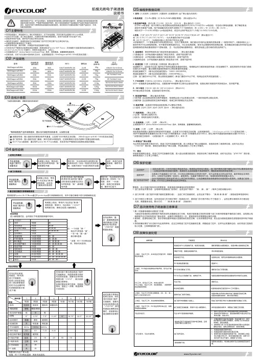
持续电流(散热良好)瞬间电流(散热良好)BEC尺寸(供参考)重量(供参考)20A 30A 40A 60A 30A 40A 55A 80A 锂电池型号79g 35g 36g 76g 49x23.5x13.5mm 65.5x34x21mm● 反推功能,支持飞行过程中切换电机正反向,达到减速目的(WinDragon wifi 80-130A 支持此功能)。
2-4S 2-4S 2-6S 2-6S 8.4V/7.4V/6V/5V ,5A 80A 100A 119g 2-6S 100A 120A 125g 2-6S 130A150A130g82.5x39.5x23.5mm2-6S航模无刷电子调速器WinDragon wifi 130AWinDragon wifi 100A WinDragon wifi 80A WinDragon wifi 60A WinDragon wifi 30A WinDragon wifi 40A WinDragon wifi 20A 8.4V/7.4V/6V/5V ,5A 8.4V/7.4V/6V/5V ,5A 8.4V/7.4V/6V/5V,5A8.4V/7.4V/6V/5V ,5A 82.5x39.5x23.5mm 82.5x39.5x23.5mm 65.5x34x21mm 49x23.5x13.5mm 02 产品规格04 操作说明1.正常工作模式2.油门行程设定3.通过遥控器进行参数编程设定推荐使用Flycolor Wi-Fi Trans 通过Flycolor App 进行参数编程设定。
另外可通过编程卡进行参数编程设定1. 刹车: [1] 无刹车 [2]软刹车 [3]重刹车 [4]很重刹车 (出厂默认值为无刹车)2.电池类型: [1]LiPo(锂电) [2] NiCb/NiMh(镍氢/镍隔) (默认值为Li Po )3.低压保护阈值:低/中/高 [1] 2.8V [2]3.0V [3]3.2V ;默认值为中(3.0V)对于Ni-xx电池组:低/中/高中止电压是电池组初始电压值的50%/65%/75%对于Li-xx电池组:可自动计算电池数量,除了确定电池 类型外无需用户设置。
爱立信PDG23N0150P2MN电源保护筋胶电路保护器说明书

Eaton PDG23N0150P2MNEaton Power Defense molded case circuit breaker, Globally Rated, Frame 2, Three Pole, 150A, 85kA/480V, PXR25 LSI w/ Modbus RTU and Relays, No TerminalsGeneral specificationsEaton Power Defense molded case circuit breakerPDG23N0150P2MN 78667927094388.9 mm 152.4 mm 104.6 mm 1.82 kg Eaton Selling Policy 25-000, one (1) year from the date of installation of theProduct or eighteen (18) months from thedate of shipment of the Product,whichever occurs first.RoHS Compliant UL 489IEC 60947-2CCC MarkedCSAProduct NameCatalog Number UPCProduct Length/Depth Product Height Product Width Product Weight WarrantyCompliancesCertifications150 AComplete breaker 2Three-polePD2 Global Class A PXR 25 LSIModbus RTU600 Vac600 VNo Terminals85 kAIC at 480 Vac 22 kAIC Icu @125 Vdc 150 kAIC @240V (UL) 22 kAIC Icu @250 Vdc65 kAIC Icu/ 40 kAIC Ics/ 143 kAIC Icm @480V Brazil (IEC) 30/25 kAIC @600V (UL/CSA)30/25 kAIC Icu/ 15/13 kAIC Ics @525V South Africa (IEC) 70 kAIC Icu/ 50 kAIC Ics/ 154 kAIC Icm @440V (IEC) 70 kAIC Icu/ 70 kAIC Ics/ 154 kAIC Icm @380-415V (IEC) 85 kAIC @480V (UL)150 kAIC Icu/ 100 kAIC Ics/ 330 kAIC Icm @240V (IEC) 10 kAIC Icu/ 5 kAIC Ics/ 21 kAIC Icm @690V (IEC) 25 kAIC @600V (UL/CSA)Eaton Power Defense MCCB PDG23N0150P2MN 3D drawingAmperage Rating Circuit breaker frame type Frame Number of poles Circuit breaker type Class Trip Type Communication Voltage rating Voltage rating - max Terminals Interrupt rating Interrupt rating range 3D CAD drawing packageApplication notesConsulting application guide - molded case circuit breakersPower Xpert Protection Manager x32Power Xpert Protection Manager x64BrochuresPower Defense technical selling bookletPower Defense brochurePower Defense molded case circuit breaker selection posterPower Defense molded case circuit breakers - Frame 2 product aid CatalogsPower Xpert Release trip units for Power Defense molded case circuit breakersMolded case circuit breakers catalogCertification reportsPDG4 CCC certificationPDG4 CB reportEU Declaration of Conformity - Power Defense molded case circuit breakersPDG2 CB reportPower Defense Declaration concerning California’s Proposition 65 Installation instructionsPower Defense Frame 2 global terminal shield, 3 pole - IL012330EN Power Defense Frame 1-2-3-4 IP door barrier assembly instructions -IL012278ENPower Defense Frame 2 multi wire connector kit -PDG2X3(2)(4)TA2253W instructions - IL012243EN H01Power Defense Frame 2 terminal kit - PDG2X3(2)(4)TA225RF instructions - IL012245EN H01Power Defense Frame 2 tunnel terminal kits - PDG2X1TA225K instructions- IL012239EN H01Power Defense Frame 2 screw terminal_end cap kit, 225A, 3 pole instructions - IL012258EN H01Power Defense Frame 2 Direct Rotary Handle Assy With Interlock Version Instructions (IL012138EN).pdfPower Defense Frame 1 IEC and Frame 2 Rotary Mechanism with NFPA Handle Attachment Instructions (IL012260EN).pdfPower Defense Frame 2 tunnel terminal (aluminum), 50A, 3 pole instructions - IL012236EN H03Power Defense Frame 2 locking devices and handle block instructions - IL012149ENPower Defense Frame 2/3/4/5/6 voltage neutral sensor module wiringinstructions – IL012316ENPower Defense Frame 2 handle mech variable depth rotary handle instructions - IL012136ENPower Defense Frame 2 handle mech direct rotary handle instructions - IL012134ENPower Defense Frame 2 tunnel terminal (aluminum), 100A, 3 pole instructions - IL012237EN H03Power Defense Frame 2 box terminal (steel), 100A, 3 pole instructions - IL012234EN H03Power Defense Frame 2 box terminal (aluminum), 225A, 3 pole instructions - IL012235EN H03Power Defense Frame 2 terminal kit - PDG2X3(2)(4)TA150RF instructions - IL012244EN H01Power Defense Frame 2 tunnel terminal (aluminum), 150A, 3 pole instructions - IL012238EN H03Power Defense Frame 2 PDG2 and PDC(E)9 breaker instructions -IL012106ENPower Defense Frame 2 multi wire connector kit -PDG2X3(2)(4)TA2256W instructions - IL012242EN H01Power Defense Frame 2 clamp terminal (steel), 20A, 3 pole instructions - IL012246EN H03Power Defense Frame 2 shunt trip UVR instructions - IL012130EN Power Defense Frame 2 Bell Alarm Switch Instructions (IL012154EN).pdf Power Defense Frame 2 bell alarm switch instructions - IL012154EN Installation videosPower Defense Frame 2 Locking Devices and Handle Block Animated Instructions.pdf.rhPower Defense Frame 2 TMTU Aux, Alarm, ST and UVR Animated Instructions.rhPower Defense Frame 2 Handle Mech Variable Depth Rotary Handle Animated Instructions.rhPower Defense Frame 2 Bell Alarm with PXR Animated Instructions.pdf.rh Power Defense Frame 2 withTMTU, Shunt Trip_UVR Animated Instructions.rhMultimediaPower Defense Frame 2 Variable Depth Rotary Handle Mechanism Installation How-To VideoPower Defense Frame 2 Aux, Alarm, Shunt Trip, and UVR How-To Video Power Defense Frame 3 Variable Depth Rotary Handle Mechanism Installation How-To VideoPower Defense Frame 2 Direct Rotary Handle Mechanism Installation How-To VideoEaton Corporation plc Eaton House30 Pembroke Road Dublin 4, Ireland © 2023 Eaton. All Rights Reserved. Eaton is a registered trademark.All other trademarks areproperty of their respectiveowners./socialmediaEaton Power Defense for superior arc flash safety Power Defense molded case circuit breakers Power Defense Frame 5 Trip Unit How-To Video Power Defense Frame 6 Trip Unit How-To Video Power Defense Breakers Eaton Specification Sheet - PDG23N0150P2MN Power Defense time current curve Frame 2 - PD2Molded case and low-voltage power circuit breaker health Making a better machineSingle and double break MCCB performance revisited Intelligent power starts with accurate, actionable data Intelligent circuit protection yields space savings Safer by design: arc energy reduction techniques Molded case and low-voltage breaker healthSpecifications and datasheetsTime/current curvesWhite papers。
LG OTW150 Wall Mounting Bracket安装手册说明书

Install ManualWall mounting bracketPlease read this manual carefully before operating your set and retain itfor future reference.OTW150P/NO: MFL63640589 (1503-REV01)5ENGLISH3How to install the wall mountWall mount screw→If the screw cannot be assembled in the designated location inevitably, it can be assembled by rearranging to the closestlocation. But, do not change 2 or more locations from the designated spot.→Assemble the wall mount screw on 2 left and 2 right location on the top part and 1 left and 1 right location on the bottom part.→At this time, use a + driver (manual or motorized) or 8 mm wrench to tighten the screw so that the wall, wall bracket and screw are completely pressed against one another.4How to assemble the wall mount support and display- Always install the display with 2 or more people.* A ssembling the wall mounting bracket, product and safety clip.*C aution - P revent the power cord from being pinched between the wall mounting bracket and the set during installation.(A pinched power cord may cause damage to the product.)* Locations of the bottom guide spacers55/65EF9500 ,65EG9600 MODEL55EG9600/55EG9200 MODELSafety clip screwSafety clip1. Set the display with the guide spacer assembled on the wall mount bracket on the wall in arrow direction. At this time, align the bottom assembly part and lift the set up lightly to align the top part.2. When adjusting the location, assemble the provide safety clip as shown in the picture to prevent the product from moving. Tighten the safety clip screw completely. If the safety clip is not tightened as shown in the picture, the product can fall off.→Pull on the bottom of the set to make sure the display is secure.→When fixing the product with the speaker to the wall, hold and lift up the product, not the speaker. →When installing a display rotated, only rotate the display 90 degrees (portrait mode).→Make sure to keep a certain level of distance from the wall so that excessive force is not applied on the cable or accessory.→When you push the product with excessive force, the product can be damaged.5How to level the Display-After installing the display, check to make sure it is level.(The product goes up or down according to the rotation direction of the screw.)± 10 mm (Leveling)6How to Organize Cables and Attach Protective Cushions-Organize the cables as shown in the illustration. Please purchase a band for cable organization, or use the band that comes with the TV.-Attach the protective cushions to minimize the impact between the wall and the TV in case they bump against each other when adjusting the angle. Attach them in the desired positions, as illustrated.Set protection cushionPrevent the power cord and the cables from being pinched between the wall mounting bracket and the wall.6。
朵唯D2完整版说明书_V1.0
目录
目 录 ............................................................................................................... 2 一、注意事项 ........................................................................................................................................ 5
1 安全事项............................................................................................................................................ 5 1.1 交通安全第一................................................................................................................................. 5 1.2 在医院里应关机............................................................................................................................. 5 1.3 在飞机上应关机...........................................................................................
Vishay电阻器产品说明书

Wirewound Resistors, Industrial Power, Silicone Coated,Fixed Edgewound TubularLINKS TO ADDITIONAL RESOURCESFEATURES•High temperature silicone coating •Complete welded construction•Excellent stability in operation (< 3 % change in resistance)•Material categorization:for definitions of compliance please see/doc?999123D 3D3D ModelsSTANDARD ELECTRICAL SPECIFICATIONSGLOBAL MODEL HISTORICAL MODEL POWER RATINGP 25 °C WRESISTANCE RANGEΩRESISTANCE RANGEΩWEIGHT (typical)g ± 5 %± 10 %FSE0050FSE-5050 1.0 to 3.8 1.0 to 3.818FSE0090FSE-90900.10 to 5.70.10 to 5.736FSE0100FSE-100100 1.0 to 6.10.15 to 6.141FSE0110FSE-110110 1.0 to 7.40.20 to 7.449FSE0120FSE-120120 1.0 to 8.60.1 to 8.654FSE0140HLZ-1401400.08 to 9.00.08 to 9.0109FSE0155FSE-155155 1.0 to 12.50.1 to 12.5129FSE0165HLZ-1651650.35 to 13.00.35 to 13.091FSE0180HLZ-1651650.35 to 13.00.35 to 13.091FSE0240FSE-240240 1.0 to 180.1 to 18186FSE0300FSE-300300 1.0 to 250.15 to 25236FSE0375FSE-375375 1.0 to 320.20 to 32286FSE0420FSE-420420 1.0 to 35.80.25 to 35.8320FSE0500FSE-500500 1.0 to 46.20.30 to 46.2381FSE0750FSE-750750 1.0 to 81.30.35 to 81.3654FSE1000FSE-10001000 1.0 to 101.60.40 to 101.6817FSE1500FSE-150015001.0 to 135.50.25 to 135.51090GLOBAL PART NUMBER INFORMATIONGlobal Part Numbering Example: FSE050021E15R0JE (visit Vishay Dale parts numbering manual for all options)GLOBAL MODEL (7 digits)TERMINAL DESIGNATION (2 digits)TERMINAL FINISH (1 digit)VALUE (4 digits)TOLERANCE (1 digit)PACKAGINGCODE (1 digit)SPECIAL (up to 2 digits)(see Standard Electrical Specifications Global Model column for options)0615202122E = lead (Pb)-freeR = decimal 1R50 = 1.5 ΩJ = ± 5 %K = ± 10 %E = lead (Pb)-freebulk pack(dash number)from 1 to 99 as applicable 91 = 100 style BKT 92 = 200 style BKT 93 = 300 style BKT CT = center tapHistorical Part Number Example: FSE-500-15-5 %FSE-50015 Ω5 %HISTORICAL MODELRESISTANCE VALUETOLERANCESPECIALSE 050021E 15R 0F J EDistance center to centerLengthO.D.I.D.MOUNTING HARDWARE FOR FSE PRODUCTS - Dimensions in inches (millimeters)91 = 100 Style Horizontal 1 High Bracket92 = 200 Style Push-In Bracket93 = 300 Style Thru-Bolt BracketBRACKET TYPE XYZHMOUNTING SLOTCB102 1.063(27)0.750(19.05)0.859(21.82) 1.250(31.75)0.219 x 0.438(5.56 x 11.13)0.750(19.05) 1.750(44.45)103 1.063(27) 1.250(31.75) 1.000(25.40) 1.500(38.10)0.281 x 0.563(7.14 x 14.30)0.927(23.55) 2.125(53.98)1041.952(49.58)2.500(63.50) 1.478(37.54) 3.000(76.20)Open slot x0.406(10.31)1.375(34.93) 4.250(107.95)BRACKET TYPE X H Y Z HOLE (DIA.)2040.700(17.78)0.578(14.68)0.250(6.35)0.500(12.70)0.156(3.96)2060.846(21.49)0.800(20.32)0.375(9.53)0.600(15.24)0.343 x 0.213(8.71 x 5.41)2070.700(17.78)1.125(28.58)0.500(12.70)0.687(17.45)0.250 x 0.188(6.35 x 4.78)BRACKET TYPE X(APPROXIMATE)THREAD 3020.271 (6.88)10-323030.463 (11.76)1/4-20Centering washerMica MOUNTING HARDWAREGLOBAL MODELAVAILABLE BRACKET TYPES BY MODEL91 = 100 STYLE HORIZONTAL1 HIGH BRACKET92 = 200 STYLE PUSH-IN BRACKET93 = 300 STYLE THRU-BOLT BRACKETFSE0050102206302FSE0090102204302FSE0100102206302FSE0110102206302FSE0120102206302FSE0140103205303FSE0155103207302FSE0165102206303FSE0180102206303FSE0240103207302FSE0300103207303FSE0375103207303FSE0420103207303FSE0500103-302FSE0750104-303FSE1000104-303FSE1500104-303TECHNICAL SPECIFICATIONSPARAMETER UNIT RESISTOR CHARACTERISTICSPower Rating W 50 to 1500Resistance Range Ω0.10 to 135.5Resistance Tolerance %5, 10Temperature Coefficient ppm/°C ± 260 for 20 Ω and above, ± 400 for 1 Ω to 19.99 ΩOperating Temperature °C -55 °C to 350 °CTemperature Rise °C 325 °C above an ambient of 25 °CMaximum Altitude f.a.s.l.10 000Short-Term Overload -10x rated power for 5 sSurge Windings-Available Maximum Working Voltage -(P x R)0.5Insultation Resistance Ω1MDielectric Voltage V RMS 1000 V AC from terminal to mounting hardwareCreepage -Varies by wattage, see “Terminal Setback” in Dimensions tableTerminal Sleeves -n/aInductanceμHVaries by wattage and resistanceNon-Inductive Winding -n/a Terminal Strengthlb 10 lbsElectrical or Mechanical Customization-Contact factory: ************************MATERIAL SPECIFICATIONSElement Copper-nickel alloy or nickel-chrome alloy, depending on resistance valueCore Cordierite, steatiteCoatingSpecial high temperature siliconeStandard Terminals Tinned alloy 42Optional Terminals Alloy 42Terminal Bands Alloy 42Part MarkingHEI, model, wattage, value, tolerance, date codeLegal Disclaimer Notice VishayDisclaimerALL PRODU CT, PRODU CT SPECIFICATIONS AND DATA ARE SU BJECT TO CHANGE WITHOU T NOTICE TO IMPROVE RELIABILITY, FUNCTION OR DESIGN OR OTHERWISE.Vishay Intertechnology, Inc., its affiliates, agents, and employees, and all persons acting on its or their behalf (collectively,“Vishay”), disclaim any and all liability for any errors, inaccuracies or incompleteness contained in any datasheet or in any other disclosure relating to any product.Vishay makes no warranty, representation or guarantee regarding the suitability of the products for any particular purpose or the continuing production of any product. To the maximum extent permitted by applicable law, Vishay disclaims (i) any and all liability arising out of the application or use of any product, (ii) any and all liability, including without limitation special, consequential or incidental damages, and (iii) any and all implied warranties, including warranties of fitness for particular purpose, non-infringement and merchantability.Statements regarding the suitability of products for certain types of applications are based on Vishay's knowledge of typical requirements that are often placed on Vishay products in generic applications. Such statements are not binding statements about the suitability of products for a particular application. It is the customer's responsibility to validate that a particular product with the properties described in the product specification is suitable for use in a particular application. Parameters provided in datasheets and / or specifications may vary in different applications and performance may vary over time. All operating parameters, including typical parameters, must be validated for each customer application by the customer's technical experts. Product specifications do not expand or otherwise modify Vishay's terms and conditions of purchase, including but not limited to the warranty expressed therein.Hyperlinks included in this datasheet may direct users to third-party websites. These links are provided as a convenience and for informational purposes only. Inclusion of these hyperlinks does not constitute an endorsement or an approval by Vishay of any of the products, services or opinions of the corporation, organization or individual associated with the third-party website. Vishay disclaims any and all liability and bears no responsibility for the accuracy, legality or content of the third-party website or for that of subsequent links.Except as expressly indicated in writing, Vishay products are not designed for use in medical, life-saving, or life-sustaining applications or for any other application in which the failure of the Vishay product could result in personal injury or death. Customers using or selling Vishay products not expressly indicated for use in such applications do so at their own risk. Please contact authorized Vishay personnel to obtain written terms and conditions regarding products designed for such applications. No license, express or implied, by estoppel or otherwise, to any intellectual property rights is granted by this document or by any conduct of Vishay. Product names and markings noted herein may be trademarks of their respective owners.© 2023 VISHAY INTERTECHNOLOGY, INC. ALL RIGHTS RESERVED。
贴片三极管W
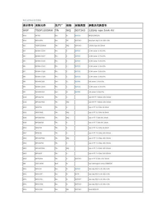
BFP183TRW
Tfk
WQ
npn rf fT 7.4 GHz 10V 65mA
W83
BFP183T
Tfk
X
npn rf fT 7.4 GHz 10V 65mA
W92
BFP92AW
Tfk
X
SOT343
npn rf fT 6 GHz 15V 30mA
WB
2SD1383K
Roh
N
npn darlington comp 2SB852K
WMs
BCR183W
Sie
N
SOT323
pnp dig 50V 10k+10k
WMs
BCR183T
Sie
N
SC75
pnp dig 50V 10k+10k
WMs
BCR183U
Sie
N
SOT457
pnp dig 50V 10k+10k
WMs
BCR183S
Sie
DO
SOT363
dual pnp dig 50V 10k+10k
WKs
BCR119W
Sie
N
SOT323
npn dig 50V 0.1A 4k7
WLs
BCR146
Sie
N
SOT23
dual npn dig 50V 47k+22k
WLs
BCR146W
Sie
N
SOT323
dual npn dig 50V 47k+22k
WMs
BCR183
Sie
N
SOT23
pnp dig 50V 10k+10k
XL1509 DEMO board 说明书
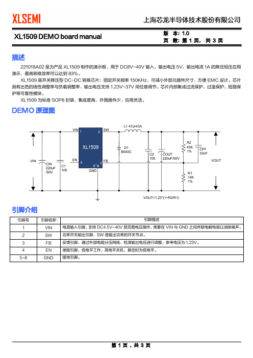
页数:第1 页,共3 页描述221018A02是为产品XL1509制作的演示板,用于DC8V~40V输入,输出电压5V,输出电流1A的降压恒压应用演示,最高转换效率可以达到83%。
XL1509是开关降压型DC-DC转换芯片;固定开关频率150KHz,可减小外部元器件尺寸,方便EMC设计。
芯片具有出色的线性调整率与负载调整率,输出电压支持1.23V~37V间任意调节。
芯片内部集成过流保护、过温保护、短路保护等可靠性模块。
XL1509为标准SOP8封装,集成度高,外围器件少,应用灵活。
DEMO原理图引脚介绍页 数:第 2 页, 共 3 页物料清单序号 数量 参考位号 说明生产商型号 生产商 1 2 C1,C2 1uF,50V,Ceramic,X7R,0805 C2012X7R1H105K TDK 2 1 CFF 33nF,50V,Ceramic,X7R,0603 C1608X7R1H333K TDK 3 2 CIN, COUT220uF,50V,Electrolytic,(10*16) YXJ-50V-220uFRubycon 4 1 D1 40V,5A,SMC,Schottky Barrier RectifierB540CDIODES5 1 L1 47uH,3A,(12*6.5)6 1 R1 14K Ω,1%,1/16W,Thick Film,0603 RC0603FR-0714KL Yageo7 1 R2 43K Ω,1%,1/16W,Thick Film,0603 RC0603FR-0743KLYageo 8 1U140V,2A,BUCK,DC-DC Converter,SOP8XL1509XLSEMIDEMO 实物图PCB 布局35mm顶层 底层25mm页数:第3 页,共3 页应用信息输入电容选择在连续模式中,转换器的输入电流是一组占空比约为VOUT/VIN的方波。
为了防止大的瞬态电压,必须采用针对最大RMS电流要求而选择低ESR(等效串联电阻)输入电容器。
EG1503电源芯片数据手册V1.2
9.1
封装尺寸 SSOP24
.............................................................................................................................. 20
9.2
封装尺寸 SOP8
描述 2.
..................................................................................................................................................................... 4
............................................................................................................................ 5
4.3.
引脚描述 SSOP24
................................................................................................................................ 6
3. 应用领域 手机移动电源 电动车智能和非智能充电器 锂电池充电器 Buck 降压电源
移动设备电源系统 Boost 升压电源 AC/DC 开关电源 可编程数字电源
2013 ©屹晶微电子有限公司 版权所有
4 / 22
屹晶微电子有ቤተ መጻሕፍቲ ባይዱ公司
压力容器设计审核人员培训GB1503-XXXX压力容器第3

54
二、密封结构
GB150.3-2011《压力容器 第3部分 设计》附录C
[ ]tf 设计温度下法兰的许用应力
49
H
R
2
[ ]tf
H T
2
[ ]tf
H 轴向应力 R 径向应力 T 环向应力
[ ]tf 设计温度下法兰的许用应力
50
7.5.3.5 法兰刚度校核
当法兰在相同的操作条件下有成功的使用经验时, 可以免除刚度校核。否则:
对整体法兰和按整体法兰计算的任意法兰,刚度指 数按(7-23)计算:
J
52.14VI MO
λ
Eδ
2 o
K1ho
1
51
式中: K1—刚度系数,取0.3 E—法兰材料的弹性模量,Mpa; 当法兰设计力矩Mo为预紧控制时,E取常温下的弹性模量, 当法兰设计力矩Mo为操作控制时,E取设计温度下的弹性模量, 其他系数同7.5.3.1
立式容器的槽面或凹面应向上,卧式容器的 槽面或凹面应位于筒体上。
22
⑺ 法兰热处理
碳素钢或低合金钢制法兰在下列任一情况下 进行正火热处理: a、法兰断面厚度大于50mm ; b、锻制法兰。
用碳素钢或低合金钢板材或型材制造的法兰环 对接接头、焊制整体法兰,应经焊后热处理。
23
⑻ 选用标准法兰的步骤
a、按照公称直径DN和设计压力P确定法兰类型。 b 、按照P≤[P]的原则确定法兰的公称压力PN。 c、按照公称直径DN和公称压力PN,查出法兰的各
部分尺寸,并标记出标准代号。
24
5、非标法兰设计( GB150.3-2011第7章)
⑴ 螺栓法兰连接设计的内容 a. 确定垫片材料、型式及尺寸; b. 确定螺栓材料、规格及数量; c. 确定法兰材料、密封面型式及结构尺寸; d. 进行应力校核, 计算中所有尺寸均不包括腐蚀
潍柴电力原装发电机组技术说明书

潍柴电力原装720kW柴油发电机组技术说明书潍柴重机股份有限公司产品名称潍柴电力原装柴油发电机组机组品牌潍柴(原装)机组型号WPG900/B73机组产地山东·潍坊柴油机品牌潍柴柴油机型号12M33D792E310柴油机产地山东·潍坊发电机品牌潍柴发电机型号WHA-900-4/0.4智能控制器品牌潍柴智能控制器型号WHC9320断路器电动开关机组尺寸(mm)4340×1992×2140机组重量(kg)7000二、输出功率描述2.1主用功率(基本功率PRP)定义:在商定的运行条件下,并按制造商规定的维修间隔和方法实施维护保养,发电机组能每年运行时间不受限制地为可变负载持续供电的最大功率。
2.2备用功率(限时运行功率LTP)定义:在商定的运行条件下,并按制造商规定的维修间隔和方法实施维护保养,发电机组每年供电达500h的最大功率。
本项目潍柴机组功率按照此功率进行标定。
三、规范性引用文件潍柴柴油发电机组的设计、制造符合下列标准:GB/T20136-2006《内燃机电站通用试验方法》JB/T50054-1999《内燃机电站可靠性考核评定方法》JB/T10303-2001《工频柴油发电机组技术条件》GB/T2820-2008《往复式内燃机驱动的交流发电机组》系列标准JB/T6755-1993《柴油发电机组成套开关设备》JB/T8194-2001《内燃机电站术语》四、环境条件4.1机组的功率标定条件a)绝对大气压力,PX:100kPa(或海拔高度0米);b)环境温度,Tr:298K(25℃);c)空气相对湿度Φr:30%。
4.2机组在下列条件下,应能输出额定功率:a)海拔高度≤1000米;b)环境温度≤40℃;c)空气相对湿度Φr:≤90%。
4.3机组在下列条件下,应能输出规定功率(允许修正功率)并可靠地工作:a)海拔高度不超过3000m;b)环境温度:下限值-25℃,上限值50℃;c)空气相对湿度:最湿月平均最高相对湿度为95%(25℃)五、发电机组的主要技术规格机组型号WPG900/B73输出功率/容量(kW/kVA)720/900额定电压(V)400/230额定频率(Hz)50额定电流(A)1299额定功率因数0.8(滞后)额定转速(r/min)1500相数及接法三相四线、星形接法冷却方式闭式循环强制水冷启动方式DC24V电启动调压方式自动励磁方式无刷励磁绝缘等级H防护等级IP23控制方式手动、自动散热水箱设计温度(℃)≤45六、发动机的主要技术规格机组型号WPG900/B73柴油机品牌潍柴型号12M33D792E310功率(kW)792额定转速(r/min)1500型式V型、高压共轨进气方式增压中冷冲程数4气缸数12燃油系统高压共轨泵调速方式电控ECU调速缸径/行程(mm)150/185排气量(L)39.2机油容量(L)113防冻液容量(L)198启动方式DC24V电启动冷却方式闭式循环强制水冷曲轴旋转方向逆时针(面向飞轮端)七、发电机的主要技术规格机组型号WPG900/B73发电机发电机品牌潍柴型号WHA-900-4/0.4额定功率(kW)720额定转速(r/min)1500额定频率(Hz)50额定电压(V)400/230额定电流(A)1299额定功率因数0.8(滞后)波形正弦波相数及接法三相四线、星形接法、励磁方式无刷励磁调压方式自动绝缘等级/温升等级H防护等级IP23八、机组的主要性能指标8.1机组的主要性能指标(一)性能参数单位运行极限值电压稳定电压偏差δUst%≤±1瞬态电压偏差突减100%负载δU+dyn%≤+20突加负载δU-dyn%≤-15电压恢复时间s≤5电压不平衡度δU%1空载电压调整范围%不小于95~105频率频率降δfst%≤3稳态频率带βf%≤0.5瞬态频率偏差突减100%负载δf+dyn%≤+12突加负载δf--dyn%≤-10频率恢复时间s≤38.2机组的主要性能指标(二)机组型号WPG900/B73经济性指标发动机经济燃油消耗率(g/kW.h)≤198机油消耗率(g/kW.h)≤0.3环境污染限值振动单振幅幅值机组在空载、半载、满载运行时,其振动单振幅幅值≤0.5mm满载时踞机组1米处噪音(dB(A))≤115“三漏”要求机组无漏油、漏水、漏气、漏电等现象可靠性大修时间20000h 平均无故障时间1000h九、机组的主要控制功能控制屏安装潍柴控制器和电动开关,机组控制系统可以选择手动/自动模式对机组实现启停。
- 1、下载文档前请自行甄别文档内容的完整性,平台不提供额外的编辑、内容补充、找答案等附加服务。
- 2、"仅部分预览"的文档,不可在线预览部分如存在完整性等问题,可反馈申请退款(可完整预览的文档不适用该条件!)。
- 3、如文档侵犯您的权益,请联系客服反馈,我们会尽快为您处理(人工客服工作时间:9:00-18:30)。
Part Number: WP1503EB/2GD Green
Features
PRE-TRIMMED LEADS FOR PC BOARD MOUNTING. STACKABLE UNITS. COLORS CAN BE MIXED IN A SINGLE HOUSING. I.C. COMPATIBLE. BLACK CASE ENHANCES CONTRAST RATIO. WIDE VIEWING ANGLE. HIGH RELIABILITY - LIFE MEASURED IN YEARS. UL RATING : 94V-0. HOUSING MATERIAL: TYPE 66 NYLON. RoHS COMPLIANT.
Description
The Green source color devices are made with Gallium Phosphide Green Light Emitting Diode.
Package Dimensions
Notes: 1. All dimensions are in millimeters (inches). 2. Tolerance is ±0.25(0.01") unless otherwise noted. 3. Lead spacing is measured where the leads emerge from the package. 4. Specifications are subject to change without notice.
Notes: 1. 1/10 Duty Cycle, 0.1ms Pulse Width. 2. 2mm below package base. 3. 5mm below package base.
Green 62.5 25 140 5 -40°C To +85°C 260°C For 3 Seconds 260°C For 5 Seconds
Green
WP1503EB/2GD
SPEC NO: DSAF0520 APPROVED: WYNEC
REV NO: V.4 CHECKED: Allen Liu
DATE: MAY/21/2007 DRAWN: Y.L.LI
PAGE: 3 OF 4 ERP: 1102000676
元器件交易网
Units mW mA mA V
SPEC NO: DSAF0520 APPROVED: WYNEC
REV NO: V.4 CHECKED: Allen Liu
DATE: MAY/21/2007 DRAWN: Y.L.LI
PAGE: 2 OF 4 ERP: 1102000676
元器件交易网
Electrical / Optical Characteristics at TA=25°C
Symbol λpeak λD [1] Δλ1/2 C VF [2] IR Parameter Peak Wavelength Dominant Wavelength Spectral Line Half-width Capacitance Forward Voltage Reverse Current Device Green Green Green Green Green Green Typ. 565 568 30 15 2.2 2.5 10 Max. Units nm nm nm pF V uA Test Conditions IF=20mA IF=20mA IF=20mA VF=0V;f=1MHz IF=20mA VR = 5V
Notes: 1.Wavelength: +/-1nm. 2. Forward Voltage: +/-0.1V.
Absolute Maximum Ratings at TA=25°C
Parameter Power dissipation DC Forward Current Peak Forward Current [1] Reverse Voltage Operating/Storage Temperature Lead Solder Temperature [2] Lead Solder Temperature [3]
Part No. Dice Lens Type Iv (mcd) [2] @ 10mA Min. WP1503EB/2GD Green (GaP) GREEN DIFFUSED 5 Typ. 20 Viewing Angle [1] 2θ1/2 60°
Notes: 1. θ1/2 is the angle from optical centerline where the luminous intensity is 1/2 the optical centerline value. 2. Luminous intensity/ luminous Flux: +/-15%.
SPEC NO: DSAF0520 APPROVED: WYNEC
REV NO: V.4 CHECKED: Allen Liu
DATE: MAY/21/2007 DRAWN: Y.L.LI
PAGE: 1 OF 4 ERP: 1102000676
元器件交易网
Selection Guide
PACKING & LABEL SPECIFICATIONS
WP1503EB/2GD
SPEC NO: DSAF0520 APPROVED: WYNEC
REV NO: V.4 CHECKED: Allen Liu
DATE: MAY/21/2007 DRAWN: Y.L.LI
PAGE: 4 OF 4 ERP: 1102000676
