如何快速启动嵌入式系统开发
嵌入式启动流程 汇编代码解析

嵌入式启动流程:汇编代码解析1.加载引导程序嵌入式系统在加电后,第一个执行的程序通常是引导程序(Bootloader)。
它负责从存储设备中加载并执行后续的程序。
引导程序通常在启动时进行硬件设备的自检,然后从特定的存储位置(如闪存或RAM)加载后续程序。
引导程序通常使用汇编语言编写,因为它需要在硬件级别进行操作。
它负责初始化CPU、内存、硬盘等硬件设备,并确保系统环境满足后续程序的要求。
2.初始化硬件设备在引导程序之后,接下来的任务是初始化硬件设备。
这包括初始化CPU、内存、硬盘、显示器等设备。
初始化硬件设备的过程包括设置设备的寄存器、配置设备的接口等。
在这个过程中,硬件设备被配置为适合后续程序运行的状态。
3.设置内存管理器在硬件设备初始化完成后,接下来需要设置内存管理器。
内存管理器负责管理系统的内存资源,包括内存的分配、释放和保护。
内存管理器通常由操作系统内核提供,因此在加载操作系统内核之前,需要先初始化内存管理器。
4.加载操作系统内核在内存管理器初始化完成后,可以加载操作系统内核。
操作系统内核是系统的核心部分,负责管理系统资源、调度应用程序的运行等。
操作系统内核通常被压缩并保存在存储设备中,因此需要先解压缩并加载到内存中。
然后,内核会进行自身的初始化,包括设置系统时钟、配置设备驱动等。
5.启动内核并初始化系统服务在操作系统内核加载并初始化完成后,可以启动内核并初始化系统服务。
系统服务是指为应用程序提供支持的底层服务,如文件系统、网络服务等。
启动内核后,会执行一系列的系统初始化过程,包括设置系统环境变量、加载系统服务等。
这些过程完成后,系统就可以接受应用程序的请求并为其提供服务。
6.加载文件系统和应用程序在系统服务初始化完成后,可以加载文件系统和应用程序。
文件系统是存储和管理文件数据的系统,应用程序则是为用户提供服务的程序。
文件系统通常被加载到内存中,并初始化为可用的状态。
然后,可以按需加载应用程序到内存中并执行。
嵌入式linux系统的启动流程

嵌入式linux系统的启动流程
嵌入式Linux系统的启动流程一般包括以下几个步骤:
1.硬件初始化:首先会对硬件进行初始化,例如设置时钟、中
断控制等。
这一步骤通常是由硬件自身进行初始化,也受到系统的BIOS或Bootloader的控制。
2.Bootloader引导:接下来,系统会从存储介质(如闪存、SD
卡等)的Bootloader区域读取引导程序。
Bootloader是一段程序,可以从存储介质中加载内核镜像和根文件系统,它负责进行硬件初始化、进行引导选项的选择,以及加载内核到内存中。
3.Linux内核加载:Bootloader会将内核镜像从存储介质中加载到系统内存中。
内核镜像是包含操作系统核心的一个二进制文件,它由开发者编译并与设备硬件特定的驱动程序进行连接。
4.内核初始化:一旦内核被加载到内存中,系统会进入内核初
始化阶段。
在这个阶段,内核会初始化设备驱动程序、文件系统、网络协议栈等系统核心。
5.启动用户空间:在内核初始化完毕后,系统将启动第一个用
户空间进程(init进程)。
init进程会读取并解析配置文件(如
/etc/inittab)来决定如何启动其他系统服务和应用程序。
6.启动其他系统服务和应用程序:在用户空间启动后,init进
程会根据配置文件启动其他系统服务和应用程序。
这些服务和应用程序通常运行在用户空间,提供各种功能和服务。
以上是嵌入式Linux系统的基本启动流程,不同的嵌入式系统可能会有一些差异。
同时,一些特定的系统也可以添加其他的启动流程步骤,如初始化设备树、加载设备固件文件等。
嵌入式系统开发技术的使用教程

嵌入式系统开发技术的使用教程嵌入式系统是集成了硬件和软件的计算机系统,用于控制、监测和操作各种电子设备。
它们广泛应用于汽车、家电、医疗设备等领域。
本文将介绍嵌入式系统开发技术的使用教程,帮助读者快速掌握开发嵌入式系统所需的技能和工具。
一、嵌入式系统开发环境搭建在开始嵌入式系统的开发之前,我们需要准备一个合适的开发环境。
首先选择一个适用于嵌入式开发的开发板,如Arduino、Raspberry Pi等。
其次,安装并配置嵌入式开发工具链,如GCC编译器、GDB调试器等。
最后,选择一个嵌入式操作系统,如嵌入式Linux、FreeRTOS等,并将其烧录到开发板上。
二、学习编程语言嵌入式系统开发通常需要使用C/C++语言进行编程。
因此,读者应该熟悉这两种编程语言的基本语法和常用库函数。
了解数据结构和算法也是非常重要的,因为它们在嵌入式系统的开发中扮演着重要的角色。
三、嵌入式硬件编程嵌入式系统的硬件编程是十分关键的一步。
读者需要了解嵌入式系统的硬件接口和寄存器,并学会如何通过编程来控制和操作各种外设,如GPIO、UART、I2C、SPI等。
此外,理解中断的原理和处理方式也是必不可少的。
四、编写驱动程序驱动程序是连接硬件和操作系统的桥梁,读者需要学习如何编写嵌入式系统的驱动程序。
这包括了设备初始化、数据传输、中断处理等内容。
同时,了解和掌握不同类型的设备驱动框架,如字符设备驱动、I2C设备驱动等,对于实现功能强大、稳定可靠的嵌入式系统至关重要。
五、嵌入式操作系统开发对于一些复杂的嵌入式系统,使用操作系统可以提供更好的软件管理和资源调度能力。
学会开发嵌入式操作系统可以大大简化开发工作。
读者可以选择学习嵌入式Linux、FreeRTOS 等操作系统,并了解其内核结构、任务管理、内存管理等基本概念和技术。
六、调试和测试在开发过程中,调试和测试是不可或缺的步骤。
读者需要学习如何使用调试工具进行硬件和软件的调试,如GDB和JTAG等。
嵌入式项目开发流程

嵌入式项目开发流程嵌入式系统是指将计算机系统嵌入到其他设备或系统中,以实现特定功能的一种计算机系统。
嵌入式系统的开发流程是指在实际项目中,从需求分析到系统测试和维护的全过程。
下面将介绍嵌入式项目开发的一般流程。
第一步,需求分析。
在项目启动之初,需要与客户充分沟通,了解客户的需求和期望。
明确项目的功能和性能要求,确定项目的范围和目标。
在需求分析阶段,需要编写需求规格说明书,明确项目的功能模块和接口定义。
第二步,系统设计。
在需求分析的基础上,进行系统设计。
系统设计包括硬件设计和软件设计两个方面。
在硬件设计阶段,需要确定硬件平台和外围设备,进行电路设计和原理图绘制。
在软件设计阶段,需要确定软件架构和模块划分,编写软件设计说明书,明确软件的功能和接口定义。
第三步,开发实现。
在系统设计完成后,进行开发实现工作。
硬件开发包括原型制作、电路调试和外围设备连接。
软件开发包括编码实现、模块测试和集成调试。
在开发实现阶段,需要严格按照设计文档进行开发,保证软硬件的兼容性和稳定性。
第四步,系统测试。
在开发实现完成后,进行系统测试工作。
系统测试包括功能测试、性能测试和兼容性测试。
功能测试是针对系统的功能进行测试,验证系统的功能是否符合需求规格说明书。
性能测试是针对系统的性能进行测试,验证系统的性能是否满足客户的要求。
兼容性测试是针对系统的兼容性进行测试,验证系统在不同环境下的稳定性和兼容性。
第五步,系统部署。
在系统测试通过后,进行系统部署工作。
系统部署包括系统的安装和调试,用户培训和文档编写。
在系统部署阶段,需要保证系统的稳定性和可靠性,确保系统能够正常投入使用。
第六步,系统维护。
在系统部署完成后,进行系统维护工作。
系统维护包括系统的监控和更新,故障处理和优化改进。
在系统维护阶段,需要及时响应客户的需求,保证系统的稳定性和安全性。
总结,嵌入式项目开发流程包括需求分析、系统设计、开发实现、系统测试、系统部署和系统维护六个阶段。
简单描述嵌入式系统的启动流程

简单描述嵌入式系统的启动流程下载温馨提示:该文档是我店铺精心编制而成,希望大家下载以后,能够帮助大家解决实际的问题。
文档下载后可定制随意修改,请根据实际需要进行相应的调整和使用,谢谢!并且,本店铺为大家提供各种各样类型的实用资料,如教育随笔、日记赏析、句子摘抄、古诗大全、经典美文、话题作文、工作总结、词语解析、文案摘录、其他资料等等,如想了解不同资料格式和写法,敬请关注!Download tips: This document is carefully compiled by theeditor. I hope that after you download them,they can help yousolve practical problems. The document can be customized andmodified after downloading,please adjust and use it according toactual needs, thank you!In addition, our shop provides you with various types ofpractical materials,such as educational essays, diaryappreciation,sentence excerpts,ancient poems,classic articles,topic composition,work summary,word parsing,copy excerpts,other materials and so on,want to know different data formats andwriting methods,please pay attention!嵌入式系统的启动流程可以分为以下几个主要步骤:1. 上电复位:当嵌入式系统接通电源时,会发生上电复位。
物联网环境中的嵌入式系统开发流程

物联网环境中的嵌入式系统开发流程随着物联网技术的快速发展,嵌入式系统的开发变得越来越重要。
嵌入式系统是指将计算机硬件和软件嵌入到其他设备或系统中,以实现特定功能。
在物联网环境中,嵌入式系统的开发流程至关重要,它决定了系统的性能、可靠性和安全性。
本文将介绍物联网环境中的嵌入式系统开发流程。
1. 系统需求分析在嵌入式系统开发过程中,首先需要进行系统需求分析。
开发团队需要与客户或项目经理合作,明确系统的功能需求、性能需求、安全需求等。
在这个阶段,开发团队需要与客户沟通,共同确定系统的关键特性,例如实时性、功耗、通信接口等。
2. 硬件设计硬件设计是嵌入式系统开发的重要步骤之一。
在这个阶段,开发团队需要考虑选择合适的嵌入式处理器、传感器、通信模块等硬件组件。
同时,还需要进行原理图设计、电路板布局和制造等工作。
硬件设计的质量直接关系到系统的性能和稳定性。
3. 软件设计软件设计是物联网环境中嵌入式系统开发的核心环节。
在这个阶段,开发团队需要确定适用的软件架构、编程语言和开发工具。
根据系统需求分析阶段的结果,开发团队需要进行软件功能设计、任务分配和接口定义等工作。
同时,还需要进行嵌入式操作系统的移植和驱动程序的编写。
4. 集成和测试集成和测试是确保嵌入式系统性能和稳定性的关键步骤。
在这个阶段,开发团队需要将硬件和软件组件进行集成。
首先,需要进行硬件的组装和连接。
然后,将编写的软件进行整合。
在集成完成后,还需要进行系统的功能测试、性能测试和可靠性测试,以确保系统符合预期的需求。
5. 系统部署和维护当嵌入式系统开发完成后,开发团队需要进行系统的部署和维护。
在物联网环境中,系统的部署可以涉及到设备的安装和配置、网络的搭建和数据的传输等工作。
在系统部署完成后,还需要进行系统的定期维护和升级,以保证系统的正常运行和安全性。
6. 系统优化和改进嵌入式系统开发是一个不断迭代的过程,系统的优化和改进也是非常重要的。
开发团队需要根据用户的反馈和市场的需求,不断进行系统的优化和改进。
A64-OLinuXino 64位开源嵌入式计算机快速启动指南说明书

A64-OLinuXino64-bit open source embedded computer QUICK START GUIDEDocument revision B, October 2017Designed and manufactured by OLIMEX Ltd, 2017All boards manufactured by OLIMEX LTD are RoHS compliantA64-OLinuXino is a single-board open hardware computer. It is a system built on a single circuit board with all hardware for proper operation already available (such as processor, power management unit, memories, peripherals, connectors, and everything else required for basic operation).On the other hand, A64-OLinuXino can also be considered a general purpose development board. It can be used in an infinite number of ways. It can boot different operating systems and distributions. There are a number of options for accessing the operating system. The platform has free general purpose pins and popular hardware interfaces. The board allows different ways of powering. This guide doesn't cover all possible ways to setup the board – it lists the two most typical ways of accessing the board for the first time. The guide is intended for absolute beginners.1. First time setup with HDMI displayThis method might be suitable for people that lack USB ↔ serial cable but have HDMI display. It is also a method that shows the graphical user interface of the operating system. This method is prone to software issues and incompatibilities. Additional access to the board via USB ↔ serial cable is highly recommended, skip to chapter “2. First time setup with USB ↔ serial cable” if you need more details on how to set it up. 1.1. Items requiredBefore you proceed ensure that you have the following items at your disposal:1.1.1. Any version of the A64-OLinuXino board.1.1.2. An external source of power supply. It should be capable of providing at least 1A of current at 5V of voltage. If you power additional components from the board (e.g. USB modem, LCD display, keyboard, mouse, etc.) consider a power supply capable of providing at least 2A of current. The power supply should fit the on-board power jack.The on-board DC barrel jack is center positive and the inner pin is 2.0mm thick. The outer hole diameter is 6.3mm. The corresponding power supply plug (or female jack) that fits the DC barrel jack has 2.1mm inner diameter and 5.5mm outer diameter. The length of the male plug should be between 10mm and 14mm.For basic operation consider the 5V power adapters that we distribute – SY0605E and SY0605E-CHINA (note that you might need additional plug adapter if you live outside of mainland Europe).1.1.3. A monitor or display with native HDMI interface, capable of 1280×720 resolution (or marked as “HD ready” or “720p”).1.1.4. An HDMI cable compatible with the board and the monitor.1.1.5. Input peripherals – like a keyboard and a mouse. Note that the board has only one USB type A host connector exposed and only one USB micro connector exposed – you will either need specific keyboard + mouse hardware (that uses only one USB host port), or specific adapter cable (to fit the USB micro connector), or an external USB hub (USB splitter).1.1.6. A micro SD card card with an official image provided by Olimex suitable for your board. You can use own micro SD card – we provide download links to the official images at the product page and the board's wiki article. The card has to be at least 8GB of size. In this case you would need a card writer tool to prepare the card and a personal computer with Internet access that is capable of running a torrent client freely.Link to the product page, latest official images are available in the “SOFTWARE” paragraph:https:///Products/OLinuXino/A64/A64-OLinuXino/open-source-hardwareWe distribute affordable blank microSD cards here:https:///Products/Components/Storage/MICRO-SD-8GB-CLASS10/1.2. Preparation and bootOnce we have everything require we can proceed booting:1.2.1. Carefully open the box with the board. The box contains only the board in protective packaging and four (4) rubber feet.1.2.2. Remove the board from the protective packaging and place the four rubber feet at bottom of the board. Use the four mounting holes. If you have trouble inserting them straight, try pushing and rotating the rubber. Some surfaces might use conductive materials and placing the board directly over such a surface might lead to short-circuit. The rubber feet allow the board to be placed safely on a flat surface without the risk of short-circuit. Here is a picture of A64-OLinuXino-1G4GW with the four rubber feet properly placed at the bottom and important parts labeled:1.2.3. Download the archive with the latest official image from the board's web-page to your computer. Extract the archive and download theimage to the microSD card via themicroSD card reader/writer. Make sureto back-up any files located on themicroSD card since download theimage to it, would destroy any data.There are a lot of software tools thatcan be used for downloading theimage to the card. If you have noexperience under Windows use“Win32 Disk Imager” tool – point to theimage and select the drive associatedwith the card, then click Write. Refer tothe picture:1.2.4. Connect the input and output peripherals to the board. Insert the microSD card. Connect display to the HDMI of the board. Connect the keyboard and the mouse to the USB ports. Connect LAN cable if you have available. Do not connect the power supply until rest of the hardware had been already connected. The general layout that we aim for is listed below:1.2.5 Power the display and apply the power supply to the board. The graphical user interface should start automatically. By default the super user name is “root” the password is “olimex”.2. First time setup with USB ↔ serial cableThis is the most direct and recommended method of accessing the board. It allows you to access the command line interface of the Linux operating system of the A64 board via your personal computer. Some server Linux images might lack video output capabilities at all and using a USB-serial cable would be one of the ways to access the board.This method is used to execute the video selection script.2.1. Items requiredBefore you proceed ensure that you have the items listed in the this chapter available:2.1.1. Any version of the A64-OLinuXino board.2.1.2. An external source of power supply. It should be capable of providing at least 1A of current at 5V of voltage. If you power additional components from the board (e.g. USB modem, LCD display, keyboard, mouse, etc.) consider a power supply capable of providing at least 2A of current. The power supply should fit the on-board power jack.The on-board DC barrel jack is center positive and the inner pin is 2.0mm thick. The outer hole diameter is 6.3mm. The corresponding power supply plug (or female jack) that fits the DC barrel jack has 2.1mm inner diameter and 5.5mm outer diameter. The length of the male plug should be between 10mm and 14mm.For basic operation consider the 5V power adapters that we distribute – SY0605E and SY0605E-CHINA (note that you might need additional plug adapter if you live outside of mainland Europe)2.1.3. A personal computer with serial terminal software. This guide gives information about the usage of a USB ↔ serial cable and terminal software only under Windows; users of other operating systems can get familiar with serial terminal software and its usage via a quick internet search (it is a very well known process).2.1.4. A USB ↔ serial cable with female leads with connectors for RX, TX, and GND. The cable and its drivers should be compatible with your personal computer. The cable should work at3.3V (not 5V).These adapter cables are not expensive. Such a cable can be purchased from almost any electronics store and online. We also manufacture a CH340T-based cable available here:https:///Products/Breadboarding/BB-CH340T/open-source-hardware and also we distribute PL2303XA-based cable, available here: https:///Products/Components/Cables/USB-Serial-Cable/USB-Serial-Cable-F/2.1.5. A micro SD card card with an official image provided by Olimex suitable for your board. You can use own micro SD card – we provide download links to the official images at the product page and the board's wiki article. The card has to be at least 8GB of size. In this case you would need a card writer tool, in order to prepare the card and a personal computer with Internet access that is capable of running a torrent client freely, in order to download our official images.Link to the product page, latest official images are available in the “SOFTWARE” paragraph:https:///Products/OLinuXino/A64/A64-OLinuXino/open-source-hardwareWe distribute affordable blank microSD cards here:https:///Products/Components/Storage/MICRO-SD-8GB-CLASS10/2.2. Preparation and bootOnce we have everything require we can proceed booting:2.2.1. Carefully open the box with the board. The box contains only the board in protective packaging and four (4) rubber feet.2.2.2. Remove the board from the protective packaging and place the four rubber feet at bottom of the board. Use the four mounting holes. If you have trouble inserting them straight, try pushing and rotating the rubber. Some surfaces might use conductive materials and placing the board directly over such a surface might lead to short-circuit. The rubber feet allow the board to be placed safely on a flat surface without the risk of short-circuit. Here is a picture of A64-OLinuXino-1G4GW with the four rubber feet properly placed at the bottom and important parts labeled:2.2.3. Download the archive with the latest official image from the board's web-page to your computer. Extract the archive and download theimage to the microSD card via themicroSD card reader/writer. Make sureto back-up any files located on themicroSD card since downloading theimage would destroy any previousdata. There are a lot of software toolsthat can be used for downloading theimage to the card. If you have noexperience under Windows use“Win32 Disk Imager” tool – point to theimage and select the drive associatedwith the card, then click Write. Referto the picture below:2.2.4. Insert the already prepared microSD card in the slot at the bottom of the board. It is a push-pushMicroSD connector. If you want to remove the card, do not pull it out directly – first push to release the locking mechanism and then remove it.2.2.5. Connect the USB-serial cable between your computer and the board. At the board's side use the three male pins behind the power jack – this is called the “UART debug” connector. Refer to the picture with the layout of the board on where “UART debug” is located. Connect cable's RX to the TX of the connector; cable's RX to the TX of the connector; GND of the cable ot GND of the connector.Install the drivers for your USB-serial cable if you haven't already. Make sure it is properly recognized by your personal computer – it should be listed as a serial port (COMx; TTYx; etc).2.2.6. Do not connect the power supply until rest of the hardware had been connected. The general layout that we aim for is listed below:2.2.7. Start the terminal software. If you don't have such installed, download and install such for free, few popular free options are PuTTY, TeraTerm, RealTerm. In some operating system there is serial terminal software already installed, installing additional serial terminal software might be redundant. In this guide we use PuTTY and Windows 10. The cable used is Olimex BB-CH340. The first picture on the next page shows how the serial cable gets recognized by Windows once the drivers are properly installed:The serial cable that we use gets assigned COM #2. We need this information in order to start the PuTTY on the same serial port. Start your serial terminal software. PuTTy is shown below – select the proper COM port, the speed, make sure that the connection is set to “Serial” and finally click “Open” at the bottom:This would bring a black empty window, which would be our command interface to the board once we power the board.2.2.8. Apply the power supply to the board. At this point the PuTTY terminal should report boot data information from the board, and eventually we would be requested to provide super user credentials. The user name is “root” and the password is “olimex”.If nothing shows up in the terminal quite likely RX and TX lines of the cable are swapped. Try to change RX and TX. Refer to the pictures and diagrams further up in this document.。
使用计算机进行嵌入式系统开发的教程

使用计算机进行嵌入式系统开发的教程随着科技的不断进步和发展,嵌入式系统已经成为了现代社会中不可或缺的一部分。
从智能手机到汽车电子,从家用电器到工业控制,嵌入式系统无处不在。
因此,学习如何使用计算机进行嵌入式系统开发变得尤为重要。
本文将为你提供一份简明扼要的教程,帮助你入门嵌入式系统开发。
1. 了解嵌入式系统的基础知识在开始学习嵌入式系统开发之前,我们需要先了解一些基础知识。
嵌入式系统是指嵌入到其他设备中的计算机系统,它通常具有特定的功能和任务。
与个人计算机不同,嵌入式系统通常具有更低的功耗、更小的体积和更高的可靠性要求。
了解这些基础知识将有助于我们更好地理解嵌入式系统开发的要求和挑战。
2. 选择合适的嵌入式开发平台在进行嵌入式系统开发之前,我们需要选择合适的嵌入式开发平台。
市面上有许多不同的嵌入式开发平台可供选择,如Arduino、Raspberry Pi等。
选择合适的嵌入式开发平台取决于你的需求和目标。
如果你是初学者,Arduino可能是一个不错的选择,它简单易用,适合快速入门。
如果你有更高的要求,Raspberry Pi可能更适合你,它具有更强大的处理能力和更多的扩展接口。
3. 学习嵌入式系统开发的编程语言嵌入式系统开发通常需要使用特定的编程语言,如C、C++、Python等。
学习这些编程语言将有助于我们编写嵌入式系统的控制程序。
C语言通常是嵌入式系统开发的首选语言,因为它具有高效、可靠和可移植的特点。
学习C语言的基础知识,如变量、函数、指针等,将为我们后续的嵌入式系统开发打下坚实的基础。
4. 掌握嵌入式系统的硬件接口嵌入式系统开发通常需要与各种外部硬件进行交互,如传感器、执行器等。
因此,掌握嵌入式系统的硬件接口是非常重要的。
了解各种常用的硬件接口标准,如GPIO、SPI、I2C等,以及它们的工作原理和使用方法,将有助于我们更好地与外部硬件进行通信和控制。
5. 开发嵌入式系统的应用程序一旦我们掌握了嵌入式系统开发的基础知识和技能,我们就可以开始开发自己的嵌入式应用程序了。
嵌入式mcu启动流程

嵌入式mcu启动流程
嵌入式MCU启动流程是指从MCU上电开始,到系统正常运行的整个过程。
它是嵌入式系统的基础,对于熟悉MCU编程的工程师来说,了解启动流程是非常必要的。
MCU的启动流程一般可以分为以下几个步骤:
1. 外围电路初始化:包括时钟、复位电路、IO口等外围电路初始化,这些电路的初始化对于MCU正常工作至关重要。
2. MCU内部时钟初始化:主要是设置MCU内部时钟源以及分频器等,保证MCU内部时钟的稳定性。
3. 外设初始化:根据硬件设计的需求,初始化各种外设,如串口、定时器、ADC、PWM等。
4. 系统启动代码:指MCU的启动代码,由汇编代码和C语言代码组成,包括堆栈设置、中断向量表设置、系统时钟设置等。
5. 用户应用程序启动:系统启动完成之后,用户应用程序开始运行。
以上是嵌入式MCU启动流程的主要步骤,各个步骤之间存在一定的顺序和依赖关系,必须按照一定的步骤来进行。
熟悉嵌入式MCU启动流程,可以更好地理解嵌入式系统的整体结构和运行原理,对于编写高效、稳定、可靠的嵌入式程序具有重要的指导作用。
- 1 -。
关于嵌入式系统的启动-奋斗中拥有-CSDN博客

关于嵌入式系统的启动-奋斗中拥有-CSDN博客一篇很好的讲解嵌入式linux启动的文章嵌入式Linux启动分为两个部分,系统引导与Linux启动。
系统引导将完成Linux装入内存前,初始化CPU和相关IO设备,并将Linux 调入内存的工作。
系统引导主要由BootLoader实现。
在BootLoader 将Linux内核调入内存之后,将权力交给LinuxKernel,进入Linux的启动部分。
以下详细分析启动的过程与使用的文件。
一、系统引导与BootLoaderBootLoader因嵌入式系统的不同与PC机有很大不同,这里将以Hyper250(Inter Xscale GDPXA250)的启动为例来分析。
由于没有BIOS驱动主板,EnbeddedOS必须由bootloader驱动所有的硬件,并完成硬件的初始化工作。
所有的初始化文件在hyper250/Bootloader目录下。
首先分析开机运行的分件:hyper250/Bootloader/X-Hyper250R1.1-Boot/src/start_xscale.S文件包含两个库文件:hyper250/Bootloader/X-Hyper250R1.1-Boot/src/include/config.hhyper250/Bootloader/X-Hyper250R1.1-Boot/src/include/start_xscale.h文件config.h主要完成系统各硬件的宏定义与设定,xscale.h主要完成对系统芯片的及系统操作的设定。
以下分析config.h文件:(1)存储总线设备的宏定义:定义Flash的大小、字长等信息,定义SRAM的基址、大小和块大小。
(2)动态内存设定:定义DRAM的大小、基址。
(3)软件包信息:包名称、版本号。
(4)设定BOOT LOADER的位置:在DRAM和SRAM的最大值、DRAM装入位置、栈的基址。
(5)设定kernel的位置:在DRAM和SRAM的基址、KERNEL的最大值、KERNEL中块的数量。
手把手教你入门嵌入式开发让硬件编程变得简单易懂

手把手教你入门嵌入式开发让硬件编程变得简单易懂在当今科技飞速发展的时代,嵌入式开发已成为计算机科学领域中备受关注的重要技术。
它将软件和硬件结合起来,通过编程控制硬件设备,实现各种应用功能。
对于那些刚刚接触嵌入式开发的初学者来说,这项技术可能会显得有些复杂和晦涩。
但是,只要掌握正确的方法和技巧,嵌入式开发就能变得简单易懂,就像手把手教你一样。
1. 硬件准备在开始嵌入式开发之前,首先需要做好硬件方面的准备。
准备嵌入式开发所需的硬件设备,例如开发板、传感器和其他外设。
这些硬件设备将为你提供各种学习和实践的机会。
2. 开发环境搭建接下来,需要搭建嵌入式开发的开发环境。
选择一款适合自己的集成开发环境(IDE),例如Arduino IDE、Keil等。
安装并配置好所选IDE,确保其能够正常地与硬件设备通信。
3. 学习基础知识在进行实际的嵌入式开发之前,需要先学习一些基础知识。
了解处理器架构、编程语言和常见的硬件接口等内容,为后续的开发工作打下坚实的基础。
4. 学习编程语言嵌入式开发中最常用的编程语言是C和C++。
因此,学习和掌握这两种编程语言是非常重要的。
可以通过参加培训课程、自学教材或在线教程来学习这些编程语言。
5. 掌握硬件编程嵌入式开发的核心是硬件编程。
掌握硬件编程的关键是理解各种硬件接口和协议的工作原理,并能够编写相应的驱动程序。
通过实际的练习和项目实践,逐渐提升自己的硬件编程能力。
6. 实际项目实践在理论知识的基础上,进行实际的项目实践是提高嵌入式开发能力的最佳方式。
选择一些简单的项目进行实践,例如LED灯控制、温湿度传感器应用等。
通过实践项目,不仅可以加深对嵌入式开发理论的理解,还能够锻炼自己的问题解决能力。
7. 参与开源社区参与开源社区是提升嵌入式开发能力的另一种途径。
加入嵌入式开发相关的论坛、社区或社交平台,与其他开发者交流经验和学习心得。
在开源社区中,可以学到更多实用的技术和最新的开发趋势。
嵌入式操作系统启动流程

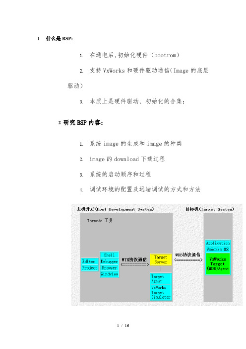
1什么是BSP:1.在通电后,初始化硬件(bootrom)2.支持VxWorks和硬件驱动通信(Image的底层驱动)3.本质上是硬件驱动、初始化的合集;2研究BSP内容:1.系统image的生成和image的种类2.image的download下载过程3.系统的启动顺序和过程4.调试环境的配置及远端调试的方式和方法5.相应BSP设置文件的修改(网络,串口..)6.BSP各文件的组成和作用.7.要对系统底层驱动清楚,也就是对CPU及相关的硬件有所了解.主要是32微处理器(上电启动过程,download image的方式方法,读写ROM,地址空间分配,MMU,寄存器,中断定义,..).参照硬件资料,多读一些源码会有所帮助.3BSP主要文件目录的组成及主要文件的作用:3.1目录target/config/All:这个目录下的文件是所有BSP文件共享的,不是特别需要不要更改里面的任何文件.configAll.h:缺省定义了所有VxWorks的设置.如果不用缺省的设置,可在BSP目录下的config.h文件中用#define或#undef方式来更改设置.bootInit.c:在romInit.s后,完成Boot ROM的第二步初始化.程序从romInit.s中的romInit()跳到这个文件中的romStart().来执行必要的解压和ROM image的放置.bootConfig.c:完成Boot ROM image的初始化和控制.usrConfig.c: VxWorks image的初始化代码.3.2目录target/config/comps/src:涉及系统核心的components,主要由target/config/All中usrConfig.c中函数调用3.3目录target/config/bspname:包含系统或硬件相关的BSP文件.Makefile一些命令行控制images的生成,参见BSP设置部分及生成下载READMEBSP发布纪录,版本,总的文档config.h包括所有涉及CPU主板的设置及定义(includes,definations),参见BSP设置文件及生成下载configNet.h网络驱动的主要设置文件,主要对END驱动设置.romInit.s汇编语言文件,是VxWorks Boot ROM和ROM based image的入口,参见系统启动部分sysALib.s汇编语言文件,程序员可以把自己的汇编函数放在这个文件里,在上层调用.VxWorks image的入口点_sysInit在这个文件里,是在RAM中执行的第一个函数.sysLib.c包含一些系统相关的函数例程,提供了一个board-level的接口,VxWorks和应用程序可以以system-indepent的方式生成.这个文件还能包含目录target/config/comps/src的驱动.sysScsi.c可选文件用于Scsi设备设置和初始化.sysSerial.c可选文件用于所有的串口设置和初始化.bootrom.hexASIC文件包含VxWorks Boot ROM代码VxWorks运行在目标机上,完整的,连结后的VxWorks二进制文件.VxWorks.sym完全的,连结后带有符号表的VxWorks二进制文件VxWorks.st完全的,连结后,standalone,带有符号表的VxWorks二进制文件4VxWorks Image4.1VxWorks images consist of:•Text segment---executable instruction.•Data segment---Initilized global and static varibles.•BSS.4.2分类和工作机理:Bootrom不是VxWorks Image,不参与讨论它本质上是一段Boot program,最少的系统初始化,主要用于启动装载VxWorks image.一般有压缩和不压缩两种形式,如bootrom和boot_uncmp.与VxWorks image的区别在于一个Bootrom调用bootConfig.c,而VxWorks调用usrConfig.c.VxWorks 本质上分为两大类:1.Vxworks分为两大类:1)Uploaded images(通过网口、串口、硬盘、软盘、DOC、ROM中加载到RAM中执行的)vxWorks - basic Tornado, shell 和 symbol table 在主机端vxWorks.st(文件很大)- 独立的 image,包含shell 和 symbol table在目标板运行2)ROM based images(直接烧入ROM的VxWorks):VxWorks_Rom类的Vxworks又分了两类:1)驻留的resident 2)不住留的1.不住留的ROM – Based VxWorks Image2.驻留的VxWorks_rom_resident2.说的再具体点:1)可下载的Vxworks image2)ROM中烧制的Image1.vxWorks_rom - Tornado in ROM,非压缩, 在RAM 中运行2.vxWorks.res_rom_nosym - Tornado in ROM, 非压缩,在 ROM 中运行3.vxWorks.st_rom - Stand-alone in ROM, 压缩, RAM 中运行4.vxWorks.res_rom - Stand-alone in ROM, 非压缩, ROM 中运行3.VxWorks在存储介质中的存放方式5启动5.1启动概述1.Bootrom 的启动最少的系统初始化,主要用于启动装载VxWorks image.一般有压缩和不压缩两种形式,如bootrom和boot_uncmp.与VxWorks image的区别在于一个Bootrom调用bootConfig.c,而VxWorks 调用usrConfig.c.文件romInit.s中的romInit()---->文件bootInit.c中的romStart()---->文件bootConfig.c中的usrInit()----->sysHwInit()----->usrKernelInit()----->Ke rnelInit(usrRoot,...)其中 /target/config/all/bootConfig.c是Boot ROM设置模块.用于通过网络加载VxWorks image.usrRoot()---->bootCmdLoop(void)命令行选择,或autobooting----->bootLoad(pLine, &entry)加载模块到内存(网络,TFFS,TSFS...)----->netifAttach()---->go(entry)-----> (entry)()从入口开始执行,不返回.•各个函数的主要作用romInit()-----power up,disable interrupt,put boot type on the stack,clears caches.romStart()-----load Image Segments into RAM.usrInit()-----Interrupt lock out,save imformation about boot type,handle all the Initialization before the kernel is actually started,then starts the kernel execution to create an initial task usrRoot().This task completes the start up.sysHwInit()-----Interrup locked,Initializes hardware,registers,activation kernelKernelInit(usrRoot,...)-----•Initializes and starts the kernel.•Defines system memory partition.•Activates a task tUsrRoot to complete initalization.•Unlocks inierrupts.•Uses usrInit()stack.usrRoot()•初始化内存分区表(memory partition library)•初始化系统系统时钟(system clock)•初始化输入输出系统(I/O system)----可选•Create devices----可选•设置网络(Configure network)--------可选•激活WDB目标通信(Activate WDB agent)---------可选•调用程序(Activate application)2.VxWorks的启动1)Loadable VxWorks的启动a)使用Bootrom进行最小系统起动b)加载程序段、数据段、BBS段c)跳转到RAM中运行的VxWorks的启动(详见下面)2)VxWork_ROM的VxWorks启动1.ROM中运行的VxWorks的启动VxWorks在ROM中运行,即写入ROM中的VxWorks是非压缩的,不需要解压,系统直接跳到ROM的首地址,运行VxWorks.注意:ROM运行的VxWorks并不支持所有的主扳,应以主扳手册为准.文件romInit.s中的romInit()---->文件bootInit.c中的romStart()---->文件usrConfig.c中的usrInit()----->sysHwInit()----->usrKernelInit()----->Ke rnelInit(usrRoot,...)VxWorks在ROM中运行主要是为了节省RAM空间,以便应用程序有更大的空间运行.只把VxWorks image的data段复制到RAM的LOCAL_LOW_ADRS, text部分留在ROM并在ROM中执行.ROM中运行的VxWorks缺点是运行速度慢.2.RAM中运行的VxWorks的启动VxWorks在RAM中运行,即写入ROM中的Boot或VxWorks Image是压缩的,需要先解压copy所有的text和data到RAM的LOCAL_LOW_ADRS中,下面sysInit()主要是初始化RAM用的,系统直接跳到RAM的首地址,运行VxWorksusrInit()前面不压缩,即romInit(),romStart()不能压缩.文件romInit.s中的romInit()---->文件bootInit.c中的romStart()---->sysaLib.s中的sysInit()---->文件usrConfig.c中的usrInit()----->sysHwInit()----->usrKernelInit()----->Ke rnelInit(usrRoot,...)RAM运行的Boot或VxWorks image的text段或data段会从ROM复制到RAM,在RAM中运行.其中usrRoot()是VxWorks启动的第一个任务,由它来初始化 driver,network等描述:romInit.s first execute in flash,minal initiliz,then jump to romStart.romStart()开始装载和解压image到RAM,sysaLib.s是在RAM中执行的第一个函数.。
- 1、下载文档前请自行甄别文档内容的完整性,平台不提供额外的编辑、内容补充、找答案等附加服务。
- 2、"仅部分预览"的文档,不可在线预览部分如存在完整性等问题,可反馈申请退款(可完整预览的文档不适用该条件!)。
- 3、如文档侵犯您的权益,请联系客服反馈,我们会尽快为您处理(人工客服工作时间:9:00-18:30)。
串虫网h 鳓 c 、 m
集 成
ห้องสมุดไป่ตู้
X LN lI X
很 多人都使用 过嵌 入式 处理器 ,
但 当一开 始在选 择一个 嵌入式处 理器
软 件 流程 《 DK S )
硬件 流 程
(P X S)
图3 简 单 的SD K 软 件 开 发 流 程 步 骤
件的整合和效 能提 升是 一个很大挑战 。
赛灵思 嵌入式 平 台
赛灵思基于 F G P A的嵌入式平 台
的基本 价值在 于为了满 足不断 提高 的
客户要求 。而嵌 入式 目标 参考 设计可
以 让 对 F G 设 计经 验 很 少 的 人 也 能 P A
够快 速开发 软件 。而 内含 目标 参考 没
计 Sa a一 p  ̄ n6和 Vr x6的 嵌 入 式 套 ie - t
件可 以有效地 管理 降低 客 户开 发进度
没计越 来越 多,我们面 临的挑 战也越
・
即便 只有 很少的 F GA设计经验 , P 也能开发软件
一
风险。
来越 多 ,主要挑战分为三个方向 :
编 程 可 以 利 用 u / . 之 类 的 R OS C OS 1 l T
甚至全嵌入式 Ln x iu 在裸金属级 完成 。
嵌入式 设计趋势及挑 战
FG P A的应用 到现在 已经有二 十
多年 的时 间了 ,我 们在各个 领域 都能
看到 各种 F G P A的应 用 ,例如 医疗 、
。 一 nI e n ● j
在 线 座 谈 ( l e S mi r 是 中 电 网 于2 0 年 推 出 的 创 新 服 务 ,通 过 “ Oni e n ) n a 00 视 频 演 示 + 专 家 解 说 +在 线 问答 ” 三 位 一 体 相 结 合 的形 式 ,充 分 发 挥 网 络 平 台 的 便
・
下 载 /渊 试 电缆 、电源
希望花更少的时间创建和调 试定
制 I P模块
一
要求能够选择正确的功能 ( 外设 )
组合
一
快速并行开发和验证软硬件
L …彻 … … 。
Oni e n r ihihs l eS mia g l t n H g
吧 仨 龋 胫
伙 1 干 . 目
ML 0 6 5基 础板
工业 控制 、汽车 电子 、连接 l P、高端 显示 、无线 、监控 、军 事通信 等 等。 然而 ,F G 内使 用嵌 入式 处理 器 的 PA
图 1 嵌 入 式 目标 参 考设 计
世 界 电 子 元 器 件 2 0 1 g ec .om 01 .2 ec. cnc
中电网 在 线 座 谈 精 华
《 ) I SE
作为系统核心时 , 考虑要点是什么呢?
一
个适 用于 该 系统 应用 的处 理器 以及
能够 正确满 足外 设功 能需求 的组 合将 会是最 后 的选择 。这 些选择 处理器 的 条件都是 F G P A嵌入式 处理的挑战 。 除此之 外 ,F GA硬 件设 计的难 P
统被整合到了 F G 上。 P A
随 着 F GA内使 用嵌入式处理器 P
虽然 F G P A的传统用 户是 硬件设 计 者 ,但 是赛 灵思 的新型嵌 入式设 计 平 台 ,使 得软 件开发 人员也 能够在 熟 悉 的 环 境 中轻 松 编 程 ,包 括 E l s cp e i I E、 D 编译器 、 调试器 、 操作系统和库 。
度必须 要有效 降低 ,能 让对 F GA经 P 验 设计 较少 的人 员也 能够开发 软件 ,
这点是因为传统 的 F GA设计工程师 , P
他 们虽然 没有硬 件的设 计经验也 要能 够 开发软件 ,这就必 须要 有一个 易于
制定的预配置 系统 。 在进 度风 险的管理 上 ,F G P A嵌
・
S a a . P A p  ̄ n6F G 嵌入式套件
・
满足 不断提 高的技术要求
一
需 要易于定制 的预配置系统
描述 :
一
要求有一个适用于该应用的处 理
器 系 统
・
降低进度风险
一
该套 件支持使用 Mi o lz c Ba e软 r
处理器 的软 件开发工作 以及使用 S atn6L 4 TF GA的硬件处 p r 一 X 5 P a 理器 系统定制工作 。
图2 E DK软 件 、硬 件 和 集 成 流 程
入式 设 计显得 额 外重要 ,由于 F GA P
嵌入式 设计包 含软件 和硬件 同时在一
个芯 片上 ,所 以 当问题发 生时 ,硬件 人 员和软 件 人员并不能 很快理 清问题 的症结 点 ,所 以常 常延 迟进 度 ,因此 在选 择 F G P A嵌 入式 系统 时 ,使用人 员往 往希 望花更 少的时 问来调 试硬 件 J P模块 ,并 同时开发 验证软件 ,软 硬
如何 快速启动嵌入 式系统 开发
Ho t tr e De eo me t f mb d e y tms Quc l w S a th v lp o t n E o e d d S se ik y
■ 赛灵思公司
为了削减成 本 ,提升性 能和保持 时问只不过是近十年的事情 ,从 1 9 器 在逐 年正向增加 中。 9 9 灵活性 ,在工 业 、医疗 、汽车 、航天 年 到现 在 ,F G P A内使 用嵌 入式 处理 和军用产 品等广 泛的应 用领域 ,包括 处 理器和 外设在 内的 完整 的嵌 入式系
w c N - l 。. w .9 暑 m
捷性 。实现 了先进 半导 体技术提供 商与 系统 设计工程师 的实 时互 动交流 ,其形式 和 内容都 广受 电子行 业工程师 的好评。本刊每 期将挑选 一些精华 内容整理成 文 ,
以 飨读 者 。欲 了解 更 多 、更 详 细 的 内容 ,敬 请 登 录 ht:s mi r c nc m。 t /e n . c . p/ ae o
