产品说明书-压差滑套
管外封投球滑套压裂技术

管外封投球滑套压裂技术董建立;马宏伟;肖诚诚;杨康敏;王新志;高俊山【摘要】Due to the fact the conventional fracturing technology cannot fracture the long horizontal section in open-hole completed horizontal well, which severely restricts the large-scale development of unconventional oil and gas, research was carried out on fractur-ing technology by ball dropping sliding sleeve outside the casing. A series of tools like K342-142 fracturing packer, PS70-140 pressure difference sliding sleeve, BS70-140 ball dropping sliding sleeve and QZ-130 setting ball seat were developed, and a multi-stage fractur-ing technical string applicable to He’nan Oilifeld was generated, which is suitable for tight sandstone fracturing and satisifes the need for rapid development of unconventional resources.%由于常规压裂技术无法实现裸眼完井水平井长水平段的压裂,严重制约了油田非常规油气资源的大规模开发,为此,进行了管外封投球滑套压裂技术研究。
21贝克HMC液控滑套

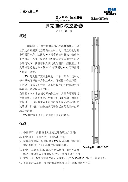
手册号:TU 10421贝克HMC液控滑套产品号:H81134概述HMC滑套是一种控制油管和环空流体循环、分隔以及选择开采油气层的高效控制工具,并且控制过程中不需要停产。
连接到HCM滑套的控制管线,使得在多个滑套、光纤、仪表或HCM滑套安装有地面控制设备的情况下,使滑套投入使用成为现实。
控制腔上很宽的旁通通道允许4条1/4”管线通过HCM,而不需另外再剥下钢管。
HCM是无停产完井系统的一个单一部件,这种无停产系统可降低停产作业成本,降低停产作业风险。
系统设计包括光纤技术,永久性仪表可实时传输更精确数据,以解释油井工况。
当需要对HCM滑套进行开关作业时,只需在地面通过控制管线加压就可实现。
从地面到HCM滑套的双控制管线设计,与目前工业上标准的安全阀系统中控制管线的设计相类似。
控制腔使用平衡活塞的设计来打开或关闭滑套。
HCM具有向上关闭,向下打开通孔的特性。
优点:1、不需停产:滑套的开关是通过地面液压力控制;2、降低成本:不需停产,不需钻机作业;3、可选择隔离层:当使用多个HCM封隔器时,就可实现可选择打开/关闭各油气层或实行混采;4、降低井眼储积效应:在短暂测试期间,由于不需要停产,所以消除了井眼储积效应,减少了停产时间。
5、重复开关:HCM滑套可在最大温度下,压差为1500PSI状况下,重复开关;6、不需要开关工具:液控滑套是通过液压力,远程控制开关的。
手册号:TU 104217、控制液:控制管线可适应水或油。
特点:在设计HCM系列滑套时,BOT(贝克石油工具公司)为其结合了几个特殊的性能,以提高其密封性能,增加工作寿命。
1、使用了现场已证明的CM密封技术;2、采用了一种用赖热高强度塑料制成的扩压环设计,使得流通孔与下部密封单元之间严格隔离;这消除了滑套开关过程中,下部密封单元的损坏。
同时由于提供了比较缓慢的高压差平衡技术,也减少了类似工具串的损坏。
3、精密的金属部件上覆盖了一层QPQ材料,它可防止“金属——金属”运动时所产生的磨损;4、开关压差在环空或油管内都可达到1500PSI;5、额定温度250°F,取决于工具的规格,参见“操作和参数指南”6、用平衡活塞打开或关闭滑套,控制腔的额定液压力与工具的工作压力相当甚至更高。
KHT循环滑套

附件三、KHT-108×53循环滑套技术规范一、结构示意图:
二、技术规范:
最大外径:φ108mm 长度:548 通径:φ40mm 打开压差:纯压差10MPa 配套钢球:φ45mm 三、用途:
该工具接于管柱上后,为打开状态(油管和套管连通状态),,当油井作业需要顶替泥浆时,可以通过该工具进行作业前的顶替泥浆作业。
投φ45mm钢球一枚,在纯压差10MPa左右可将该阀关闭。
打开压差:纯压差10MPa 配套钢球:φ45mm 三、用途:
该工具接于管柱上后,为关闭状态(油管和套管不连通),可实现下次作业的顶替泥浆压井作业,当油井需要顶替泥浆作业时,投φ45mm钢球一枚,在纯压差10MPa左右可将该阀打开,使油管和套管连通,从而进行顶替泥浆作业。
艾顿B-线系列抗滑安全网格产品说明书

Eaton’s B-Line Division, January 2009(Formerly GS Metals Corp.)3764 Longspur RoadPinckneyville, IL 62274PRODUCT GUIDE SPECIFICATIONSpecifier Notes: This product guide specification is written according to the Construction Specifications Institute (CSI) MasterFormat, Three-Part SectionFormat, and PageFormat, contained in the CSI Manual of Practice. Six-digit section numbers are from the MasterFormat, 2004 edition.The section must be carefully reviewed and edited by the Engineer to meet the requirements of the project and local building code. Coordinate with other specification sections and the drawings.Specifier Notes: This section covers Eaton’s B-Line series slip resistant grating products, including safety grating. Grating planks, walkways, treads, ladder rungs and specialty items designed for industrial and commercial walking/working surfaces are included.SECTION 05 53 00, Metal Gratings (05120)Safety Grating, Slip Resistant Walkways, Platforms and TreadsPART 1- GENERAL1.1SECTION INCLUDESA.Safety Grating walkways, planks, stair-treads with reticulated and formed metalcross struts.B.Regular and Heavy Duty Safety Grating products constructed from single-sheetwith integrally-formed channels at the edges.C.Slip resistant walkways, planks and stair-treads with stamped surfacetextures/patterns.1.2RELATED DOCUMENTS & SECTIONSDrawings and general provisions of the contract, including General andSupplementary Conditions and Division 01 Specification Sections, apply to thissection. Other related sections include:A.05 51 00, Metal Stairs05 51 19, Metal Grating Stairs05 51 13, Metal Ladders05 51 36, CatwalksB. 05 55 00, Metals Stair Treads and Nosings1.3SUBMITTALSA.Submit drawings of (Safety Grating) (Slip Resistant Grating) products,accessories and attachments.B.Submit manufacturer’s product data on (Safety Grating) (Slip Resistant Grating)products including, but not limited to; types, materials, finishes, gauge thickness, surface patterns. For each grating cross-section, submit dimensional information, span, load capacity and deflection requirements.C.Shop Drawings:1.Show fabrication and installation details, including plans.2.Coordination of drawings: Floor plans and sections, drawn to scale.Include scaled layout and relationships between grating and adjacentstructural elements.1.4REFERENCESA.ASTM A 123 – Standard Specification for Zinc (Hot-Dip Galvanized) Coatingson Iron and Steel ProductsB.ASTM A 240 – Standard Specification for Chromium and Chromium-NickelStainless Steel Plate, Sheet, and Strip for Pressure Vessels and for GeneralApplicationsC.ASTM A 653 – Standard Specification for Steel Sheet, Zinc-Coated (Galvanized)or Zinc-Iron Alloy-Coated (Galvannealed) by the Hot-Dip ProcessD.ASTM A 924 – Standard Specification for General Requirements for Steel Sheet,Metallic-Coated by the Hot-Dip ProcessE.ASTM A 1011 – Standard Specification for Steel, Sheet and Strip, Hot-Rolled,Carbon, Structural, High-Strength Low-Alloy, and High-Strength Low-Alloy with Improved FormabilityF.ASTM B 209 – Standard Specification for Aluminum and Aluminum-Alloy Sheetand PlateG.OSHA-Occupational Safety and Health Administration- Standards for walking-working surfaces. Part Number 1910, Subpart D.H.RR-G-1602D- Federal Specification For Safety Grating (other than bar type &excluding naval vessels)I.ISO 9001:2000 Quality Management System- Requirements.1.5QUALITY ASSURANCEA.Manufacturers: Firms regularly engaged in the manufacture of (Safety Grating)(Slip Resistant Grating) of the types required, whose products have been insatisfactory use in similar service for not less than 5 years.B.OSHA Compliance: All grating installations must comply with OSHA Standardsfor walking-working surfaces.C.Federal Specification RR-G-1602D (or current revision) defines the criteria foritems to be considered “Safety Grating”. Slip resistant performance data must beavailable to support compliance.D.Manufacturer must have an ISO registered quality system in place, and Manualavailable upon request.1.6DELIVERY, STORAGE AND HANDLINGA.Deliver (Safety Grating) (Slip Resistant Grating) and components carefully toavoid damage, denting and scoring of finishes. Do not install damaged material.B.Store materials in original packaging and in clean, dry space; protect fromweather and construction traffic. Materials to be elevated off of ground by blocks or skids or pallets.PART 2 PRODUCTS2.1 ACCEPTABLE MANUFACTURERSA. Safety Gratings: Subject to compliance with these specifications, SafetyGratings shall be installed as manufactured by Eaton’s B-Line Series Grip StrutSafety Grating (or engineer approved equal).B. Slip Resistant Gratings: Subject to compliance with these specifications, SlipResistant Gratings shall be installed as manufactured by Eaton’s B-Line Division (or engineer approved equal).2.2 MATERIALS AND FINISHA.Hot Rolled, Pickled & Oiled Steel: Commercial steel per ASTM A 1011,minimum yield of 33 ksi.l Galvanized Steel: Commercial steel per ASTM A 653 and ASTM A 924with G-90 coating designation, minimum yield of 33 ksi.C.Hot-Dip Galvanized After Fabrication: Commercial steel per ASTM A 1011,minimum yield of 33 ksi, hot-dip galvanized after fabrication per ASTM A 123.D.Aluminum: Alloy 5052, Temper H32 aluminum per ASTM B 209E.Stainless Steel: Type 304 (Type 316) stainless steel, 2B or 2D finish, per ASTMA 240.2.3 GRATINGS AND COMPONENTSA. Safety Grating: (planks)(walkways)(treads)(ladder rungs) shall meet or exceedthe Federal Standard for Safety Grating, RR-G-1602D.B. Slip Resistant Grating: (planks)(walkways)(treads)(ladder rungs) shall beconstructed from a single sheet with integrally formed side channels and surfacetextures.PART 3 EXECUTION3.1 INSTALLATIONA. Inspect areas to receive Grating for obstacles. Notify the Engineer ofconditions that would adversely affect the installation or subsequent utilization of the areas. Do not proceed with installation until unsatisfactory conditions arecorrected.B. Install Grating according to manufacturer’s recommendations and as shown onthe construction drawings.C. Position Grating sections flat and square with ends bearing minimum 1-1/2” onsupporting structure.D. Keep sections at least ¼” away from vertical steel sections and ½” fromconcrete walls.E. Allow clearance at joints between sections of maximum ¼” at side channelsand maximum 3/8” at ends.F. Band random cut ends and diagonal or circular cut exposed edges with aminimum 1/8” thick bar welded at contact points.G. Join abutting walkway sections with manufacturer supplied splice plates;bolted or welded as specified.END OF SECTION。
Y211型系列封隔器及配套工具使用说明书

Y211型系列封隔器及配套工具使用说明书一、概述:Y211型系列封隔器是一种机械式卡瓦封隔器,采用上提旋转再下放管柱的方式坐封,上提管柱的方式解封。
经多年的现场应用证明:该型系列封隔器具有起下顺利,中途不误坐封,坐封、解封操作简单,密封可靠,承压高,通径大,摩阻小等优点。
同时在使用上具有很大的灵活性,当单独使用该型系列封隔器时,可用于试油、验串、找水等井下作业;当与之配套的水力锚、压差式反循环阀组合使用时可用于分层压裂、分层酸化、保护油层套管等井下作业施工之中。
二、结构和工作原理:1、结构:1)、Y211型系列封隔器主要由密封、支撑、J型换向机构、中心管及上、下接头等部分组成(见附图一)。
2)、YSM型水力锚主要由锚体、锚块、弹簧、压条、衬套、胶件等部分组成(见附图二)。
3)、YFF型压差式反循环阀主要由中心管、滑套、弹簧、剪销环、控制销钉、阻尼塞、胶件等组成(见俯图三)。
2、工作原理:封隔器下井时下接头上的换向销始终位于J形钩的直槽内上下运动,保证下井的顺利进行。
当封隔器下至预定深度后,按要求上提管柱一定高度,使换向销位于J形钩直槽的上死点,正转油管使换向销脱离J形钩的直槽,然后下放管柱,使锥体下移推开卡瓦并咬在套管内壁上,继续下放管柱,胶筒受压胀大,密封油套环形空间,从而完成封隔器的坐封过程。
如果是试油、验串、找水则可进行下步作业,如果是分层压裂、分层酸化或保护油层套管,需在下封隔器前把与之配套的水力锚其上面,压裂过程中,水力锚锚块在油套压差的作用下克服复位弹簧的弹力伸出,紧紧的咬在套管的内壁上,压差越大,咬和力越大,此力可防止封隔器上串,以保证施工的顺利进行。
施工结束后,放掉油管压力,使油套压差平衡,再上提管柱封隔器既实现解封。
三、现场施工要求:1、下井前的准备工作:1)、必须用大于封隔器钢体最大外径1-2mm,长度不小于0.5m的通井规通至人工井底。
2)、用刮管器刮削套管内壁,对封隔器经过的射孔井段和坐封井段要重复刮管两次以上,刮管深度应超过坐封深度10m以上。
裸眼完井工具串示意图

裸眼完井工具串示意图西安瑞兰特石油设备有限公司-杨超2020/3/83-1/2″EUE油管2-7/8″ EUE油管7″套管水平井分段压裂工具管串结构示意图投球滑套2投球滑套1投球滑套3压差滑套带筛管引鞋+浮鞋+球座总成悬挂封隔器+回接筒回接插头裸眼封隔器扣型:3 1/2”EUE母提升短节最大外径:114 mm 最小内径:69mm 长度:1.5m 扣型:41/2”LTC公扣型:41/2”LTC母扣型:41/2”LTC公扣型:41/2”LTC母扣型:31/2”EUE公投球滑套最大外径:146mm 最小内径:32.5mm 长度:1.2m 转换接头最大外径:127mm 最小内径:69mm 长度:1.0m1.5”投球滑套示意图提升短节最大外径:114 mm 最小内径:69mm 长度:1.5m投球滑套最大外径:146mm最小内径:44.7mm长度:1.2m转换接头最大外径:127mm最小内径:69mm长度:1.0m 2.0”投球滑套示意图扣型:3 1/2”EUE母扣型:41/2”LTC公扣型:41/2”LTC母扣型:41/2”LTC公扣型:41/2”LTC母扣型:31/2”EUE公提升短节最大外径:114 mm 最小内径:69mm 长度:1.5m 扣型:41/2”LTC公扣型:41/2”LTC母扣型:41/2”LTC公扣型:41/2”LTC母扣型:31/2”EUE公裸眼封隔器最大外径:147 mm 最小内径:97mm 长度:1.2m 转换接头最大外径:127mm 最小内径:69mm 长度:1.0m裸眼封隔器示意图扣型:3 1/2”EUE母提升短节最大外径:114 mm 最小内径:69mm 长度:1.5m 扣型:41/2”LTC公扣型:41/2”LTC母扣型:41/2”LTC公扣型:41/2”LTC母扣型:31/2”EUE公压差滑套最大外径:143mm 最小内径:98mm 长度:0.8m 转换接头最大外径:127mm 最小内径:69mm 长度:1.0m压差滑套示意图扣型:\扣型:41/2”LTC公扣型:41/2”LTC母扣型:31/2”EUE公悬挂封隔器最大外径:150mm 最小内径:98mm 长度:1.4m转换接头最大外径:127mm 最小内径:69mm 长度:1.0m悬挂器及回接筒示意图回接筒最大外径:147mm 最小内径:133mm 长度:3.1m扣型:41/2”LTC公扣型:41/2”LTC母加长接头最大外径:126mm 最小内径:98mm 长度:1.4m扣型:41/2”Vam Top公扣型:41/2”Vam Top母扣型:3 1/2”EUE母提升短节最大外径:114 mm 最小内径:69mm 长度:1.5m 扣型:41/2”LTC公扣型:41/2”LTC母球座总成最大外径:127mm 最小内径:25.4mm 长度:0.9m 浮鞋最大外径:127mm 最小内径:/长度:0.6m 工具前部示意图加长接头最大外径:126mm 最小内径:100mm 长度:1.4m 扣型:41/2”LTC公带筛管引鞋最大外径:127mm 最小内径:/长度:1.1m扣型:41/2”LTC母扣型:41/2”LTC公扣型:41/2”LTC母扣型:/扣型:/提升短节最大外径:127mm 最小内径:61mm长度:1.5m回接插头最大外径:145.6 mm 最小内径:107.5mm 长度:2.0m 扣型:2 7/8”EUE母扣型:5”LTC公扣型:5”LTC母回接插头示意图。
ALPS ALPINE SSSF Series滑动开关产品基本信息说明书

|Dimensions |Mounting Hole Dimensions |Actuator Configuration |Shape of Frame Leg |Circuit Diagram |Packing Specifications |Soldering Conditions Slide Switch > SSSF Series > SSSF0215008.5(H)mm, 2.0mm-travel Type SSSF Series||Travel 2mmActuator directions Vertical Actuator length 6mm Poles 2Positions 2Operating force Refer to the dimensions.Mounting methodSnap-in (t1.6)Changeover timing Non shorting SolderingManual, DipOperating temperature range-40℃ to +85℃Part number Series Common Info SSSF021500Rating (max.)/(min.) (Resistive load)0.1A 30V DC/50μA 3V DC Electrical performanceContact resistance(Initial performance/After lifetime)25mΩ max./65mΩ max.Insulation resistance 100MΩ min. 500V DC Voltage proof 500V AC for 1 minute Mechanical performanceTerminal strength5N for 1 minuteActuator strengthOperating direction 30N Pulling direction30NDurabilityOperating life without load10,000 cycles 45mΩ max.Operating life with load (at max. rated load)10,000 cycles 65mΩ max.Environmental performance Cold-40℃ 500h Dry heat85℃ 500hDamp heat60℃, 90 to 95%RH 500hMinimum order unit (pcs.)Japan 800Export 4,000DimensionsMounting Hole DimensionsViewed from direction A in the dimensions. Actuator ConfigurationShape of Frame LegCircuit DiagramPacking Specifications BulkNumber of packages (pcs.)1 case / Japan8001 case / export packing4,000Export package measurements (mm)400×270×290Soldering Conditions Reference for Dip SolderingItems Preheating temperature100℃ max. Preheating time60s max.Dip soldering Soldering temperature260±5℃Duration of immersion10±1sReference for Hand SolderingSoldering temperature350±10℃Soldering time3+1/0sNotes are common to this series/models.1. This site catalog shows only outline specifications. When using the products, pleaseobtain formal specifications for supply.2. Please place purchase orders per minimum order unit (integer).3. Products other than those listed in the above chart are also available. Please contact usfor details.Inquiries about ProductsInquiryCOPYRIGHT© 2020 ALPS ALPINE CO., LTD。
Parker Hannifin 产品目录说明书

16
Parker Hanni�n Corporation
Parker Canada Division
Milton, ON Canada
PCD2005-5
Parker Pneumatic Vortex Flow Meter
17
Parker Hanni�n Corporation
Parker Canada Division
22
Parker Hanni�n Corporation
Parker Canada Division
Milton, ON Canada
PCD2005-5
Parker Pneumatic Vortex Flow Meter
23
Parker Hanni�n Corporation
Parker Canada Division
Milton, ON Canada
PCD2005-5
Parker Pneumatic Water Retract Actuator
8
Parker Hannifin Corporation
Parker Canada Division
Milton, ON Canada
PCD2005-5
Parker Pneumatic P8S-G Sensors
Milton, ON Canada
PCD2005-5
Parker Pneumatic Vortex Flow Meter
21
Parker Hanni�n Corporation
Parker Canada Division
Milton, ON Canada
PCD2005-5
Parker Pneumatic Vortex Flow Meter
水平井完井喷砂滑套使用说明书

《水平井完井喷砂滑套使用说明书》
1.产品用途
喷砂滑套主要用于分层压裂的分层控制,投球打开后,建立工作液通道,对储层段进行分级压裂。
2.主要技术参数
3.产品结构及工作原理
1-本体2-剪切销钉3-球座4-喷嘴
该工具主要由本体、剪切销钉、球座、喷嘴等组成;当投球到位后,进行憋压至18-20MPa,销钉剪切,球座下行,喷嘴口打开,球座及球一直滑落到上一级限位器处,封堵上一层,对本层进行压裂。
4.现场使用注意事项
球座打开压力会因地层压力系数不同有一定变化。
5.贮存、运输要求及注意事项
1) 产品各加工表面涂防锈脂,非加工表面涂漆;
2) 运输和贮存过程中应注意防潮,贮存时应放在干燥通风处,以防锈蚀。
非常规油气水平井多级分段压裂完井技术

视频
(四)水平井套管固井预置滑套分段压裂技术 关键工具-预制滑套
压裂滑套采用固井的方式进行分隔 压裂滑套采用专用的开关工具进行打开和关闭 压裂滑套内壁采用特殊涂层,有效防止固井泥浆粘留。
(四)水平井套管固井预置滑套分段压裂技术 关键工具-开关工具
开关工具通过内管大打压的方式胀开开关爪 达到一定拉力可以脱开 随连续油管下入更快捷
1.9
2.025 2.15 2.275 2.4 2.525 2.65 2.775 2.9 3.025 3.15 3.275 3.4 3.525 3.65 3.775
(一)水平井裸眼封隔器投球滑套分段压裂技术 压差式滑套
压差滑套是第一段的压裂通道,采用油管直接打压的方式打开
(一)水平井裸眼封隔器投球滑套分段压裂技术 井筒隔离阀、底部循环阀
全国天然气总产量的 1/4 以上。专家预测, 2015 年 全 国 致 密 气 产 量有望达到 500 亿立方
米。
(二)国内非常规油气发展情况 中石油非常规发展
共完成水平井分段压裂1133口井,4722段 平均单井产量是直井的 3.9 倍,增油 520 万吨, 增气145亿立方米,相当于开发一个中型油气田 自主技术应用比例达到87%以上 2011年完钻1000口水平井,500口井实现了2200 段有效压裂
平 衡 阀
丢 手 球 座
机 械 定 位 器
喷 枪 丢 手 引 导 头
(五)水平井连续油管拖动封隔器套管分段压裂技术
相关设备-压裂车组
2000型泵车8台-压裂车组
2000型泵车2台-喷砂射孔
700型泵车2套-下入循环 混砂车1部-喷砂射孔
(五)水平井连续油管拖动封隔器套管分段压裂技术 相关设备-连续油管
- 1、下载文档前请自行甄别文档内容的完整性,平台不提供额外的编辑、内容补充、找答案等附加服务。
- 2、"仅部分预览"的文档,不可在线预览部分如存在完整性等问题,可反馈申请退款(可完整预览的文档不适用该条件!)。
- 3、如文档侵犯您的权益,请联系客服反馈,我们会尽快为您处理(人工客服工作时间:9:00-18:30)。
产品使用说明书OYLYCHT142压差滑套
2012年1月
OYLYCHT142压差滑套
使用说明书
一、主要技术参数
最大外径:142mm
最小流通面积:80mm
最高工作压力:70MPa
最高工作温度:150℃
开启动力:30-35MPa
工具总长度:780mm
连接螺纹:41/2″园管螺纹
二、结构原理及用途
OYLYCHT压差滑套是一种压力差控制开启式的常闭阀,具有功能可靠、密封性能好的特点,主要有阀体、动力滑套、连接短节、下接头和剪销等组成。
工具下至设计位置后,一旦下部流体通道被封闭,管内外压力则不衡,动力滑套两端的压力不衡时,动力滑套在压力差的作用下,产生向下的推动力,当压力达到30-35MPa时,定位剪销被切断,动力滑套剪切剪销后下行,位于阀体上的出液口打开,管内外建立起流通通道,为压裂提供了工作通道。
该工具主要用于提供压裂液通道。
三、特点
1、控制可靠,操作简单;
2、复式密封,能够有效地防止渗漏;
四、操作规程
1、本工具配套于压裂管柱一起入井,工具下入前必须进行充分的通井、刮管,洗井作业时排量不能超过600L/min。
2、下井前必须严格对阀的密封性能进行检验。
3、开启时,地面打压必须平稳,待压力突降后停泵转入正常的压裂程序。
