i2000差压表说明书
压力表的操作说明书
压力表的操作说明书操作说明书一、产品概述压力表是一种常用的测量仪器,用于测量液体或气体的压力大小。
本操作说明书详细介绍了压力表的使用方法和注意事项。
二、产品结构1. 压力表外观:压力表通常由表头、表身和连接装置组成。
2. 表头:显示压力数值,并设有刻度盘和指针。
3. 表身:固定表头和连接装置,通常采用金属材料制成。
4. 连接装置:与被测介质连接,通常是螺纹接口或法兰接口。
三、操作步骤1. 准备工作在进行压力测量之前,请确保以下准备工作已完成:- 将压力表与被测介质连接,确保连接牢固。
- 检查压力表是否正常运作,并确保指针在零刻度位置。
2. 测量压力(根据实际情况选择合适的测量方法,以下是一种常用方法的步骤)- 确定被测压力介质的性质(液体或气体)和量程范围。
- 打开被测压力介质供应,使其充满压力表。
- 观察压力表指针的位置,根据刻度盘上的刻度读取压力数值。
- 记录压力数值,可以根据需要进行多次测量以提高精确度。
3. 压力表的维护- 使用结束后,及时将压力表从被测介质中取出,并用清洁软布轻轻擦拭表面。
- 避免压力表受到外界冲击或水分侵入,以防止损坏或影响准确度。
- 定期检查压力表的准确度,并根据需要进行校正或更换。
四、注意事项1. 避免超过压力表的量程范围进行测量,以免损坏仪器。
2. 避免过大的冲击或振动,以保持压力表的准确度。
3. 注意压力表的工作温度范围,避免在超出范围的温度下使用。
4. 如遇到故障或不正常情况,请及时停止使用并咨询专业人士。
五、常见问题解答1. 问:为什么压力表指针不动?答:可能是压力表与被测介质连接松动或存在堵塞,请检查连接状态并进行清洗。
2. 问:为什么压力表指针不稳定?答:可能是被测介质存在脉动或压力波动,请检查被测介质的稳定性。
3. 其他问题请咨询售后服务。
六、总结本操作说明书详细介绍了压力表的使用方法和注意事项,希望能帮助用户正确操作压力表,确保测量的准确性和使用的安全性。
2000型铸铝微压差表使用说明
2000型铸铝微压差表使用说明一、产品概述2000型铸铝微压差表是一种用于测量微小压差的仪器。
该仪器采用铸铝材料制作,具有重量轻、结构紧凑、耐腐蚀等特点,广泛应用于工业自动化领域。
二、仪器结构2000型铸铝微压差表由外壳、压差传感器、液晶显示屏等组成。
外壳采用铸铝材料制作,具有良好的耐腐蚀性和机械强度。
压差传感器内部采用高精度的电阻应变片,能够准确测量微小压差变化。
液晶显示屏用于显示压差数值。
三、使用方法1. 将2000型铸铝微压差表连接到需要测量压差的管路上,确保连接紧密,避免泄漏。
2. 打开仪器电源,待液晶显示屏亮起后,仪器即进入工作状态。
3. 在液晶显示屏上可以看到当前的压差数值,单位为帕斯卡(Pa)或毫米水柱(mmH2O)。
4. 如果需要重置仪器,可以按下仪器上的复位按钮,将压差归零。
5. 在使用过程中,如果发现仪器显示异常或不准确,可以进行校准。
校准方法请参考仪器附带的使用手册。
四、注意事项1. 在使用2000型铸铝微压差表之前,请先阅读仪器的使用手册,了解仪器的性能和使用方法。
2. 仪器应在干燥、通风良好的环境下使用,避免受到潮湿和腐蚀物质的影响。
3. 仪器应避免受到强烈的振动和冲击,以免影响仪器的测量精度。
4. 仪器不应接触高温物体,以免损坏仪器。
5. 仪器应定期进行校准和维护,以确保测量结果的准确性和可靠性。
6. 仪器在长时间不使用时,应存放在干燥、阴凉的地方,避免阳光直射和高温环境。
五、维护保养1. 定期清洁仪器外壳,使用干净的软布擦拭,避免使用有腐蚀性的化学溶剂。
2. 仪器应定期进行校准,校准方法请参考仪器附带的使用手册。
3. 如果仪器出现故障或异常,应及时联系售后服务中心进行维修或更换。
六、总结2000型铸铝微压差表是一种重要的测量仪器,在工业自动化领域具有广泛的应用。
使用该仪器能够准确测量微小压差变化,为工业生产提供可靠的数据支持。
在使用过程中,需要注意仪器的正确使用方法和维护保养,以确保测量结果的准确性和仪器的长期稳定性。
Dwyer Series 2000 Magnehelic 差压表说明书

Series2000Magnehelic® Differential Pressure GagesIndicate positive, negative, or differential. Accurate within 2%Service ManualDimensional EnlargementSelect the Dwyer Magnehelic gage for high accuracy - guaranteed within 2% of full scale - and for the wide choice of 81ranges available to suit your needs precisely. Using Dwyer's simple, frictionless Magnehelic movement, it quickly indicates low air or non-corrosive gas pressures--either positive, negative (vacuum) or differential. The design resists shock, vibration and over-pressures. No manometer fluid to evaporate, freeze or cause toxic or leveling problems. It's inexpensive, too.Widely used to measure fan and blower pressures, filter resistance, air velocity, furnace draft, pressure drop across orifice plates, liquid levels with bubbler systems and pressures in fluid amplifier or fluidic systems. It also checks gas-air ratio controls and automatic valves, and monitors blood and respiratory pressures in medical care equipment.MOUNTING. A single case size is used for most ranges of Magnehelic gages. They can be flush or surface mounted with standard hardware supplied. With the optional A-610 Pipe Mounting Kit they may be conveniently installed on horizontal or vertical 1¼" - 2" pipe. Although calibrated for vertical position, many ranges above 1 inch may be used at any angle by simply re-zeroing. However, for maximum accuracy, they must be calibrated in the same position in which they are used. These characteristics make Magnehelic gages ideal for both stationary and portable applications. A 4 9/16"hole is required for flush panel mounting. Complete mounting and connection fittings plus instructions are furnished with each instrument.Vent valvesIn applications where pressure is continuous and the Magnehelic gage is connected by metal or plastic tubing which cannot be easily removed, we suggest using Dwyer A-310A vent valves to connect gage. Pressure can then be removed to check or re-zero the gage.High and medium pressure modelsInstallation is similar to standard gages except that a 4 13/l6" hole is needed for flush mounting. The medium pressure construction is rated for internal pressures up to 35 psig and the high pressure up to 80 psig.Available in all ranges. Because of larger case, will not fit in portable case. Weight 1 lb., 10 oz. (Installationof the A-321 safety relief valve on standard Magnehelic gages often provides adequate protection against infrequent overpressure; see Bulletin S-101).PHYSICAL DATAAmbient temperature range: 20° to 140°F.* (-7° to 140°C)Rated total pressure: -20" Hg. to 15 psig.+ (-68 kPa to 103 kPa)Overpressure: Relief plug opens at approximately 25 psig (172 kPa)Connections: 1/8"' NPT female high and low pressure taps duplicated - one pair side and one pair back.Housing: Die cast aluminum. Case and aluminum parts Iridite-dipped to withstand 168 hour salt spray test. Exterior finish is baked dark gray hammerloid.Accuracy: Plus or minus 2% of full scale (3% on - 0 and 4% on - 00 ranges), throughout range at 70°F. (21°C) Standard accessories: Two 1/8" NPT plugs for duplicate pressure taps, two 1/8" pipe thread to rubber tubing adapter and three flush mounting adapters with screws. (Mounting and snap ring retainer substituted for 3 adapters in MP & HP gage accessories.)Weight: 1 lb. 2 oz. (460 g)* Low temperature models available as special option.+ For applications with high cycle rate within gage total pressure rating next higher rating is recommended. See Medium and High pressure options lower left.OPTIONS AND ACCESSORIESTransparent overlaysFurnished in red and green to highlight and emphasize critical pressures.Adjustable signal flagIntegral with plastic gage cover; has external reset screw. Available for most ranges except those with medium or high pressure construction. Can be ordered with gage or separately.LED Setpoint IndicatorBright red LED on right of scale shows when setpoint is reached. Field adjustable from gage face, unit operates on 12 -24 VDC Requires MP or HP style cover and bezel.Portable unitsCombine carrying case with any Magnehelic gage of standard range (not high pressure) includes 9 ft. (2.7 m) of 3/16"I.D. rubber tubing, stand-hang bracket, and terminal tube with holder.Air filter gage accessory packageAdapts any standard Magnehelic for use as an air filter gage. Includes aluminum surface mounting bracket with screws, two 5 ft. (1.5 m) lengths of 1/4" aluminum tubing, two static pressure tips and two molded plastic vent valves, integral compression fittings on both tips and valves.Quality design and construction featuresBezel provides flange for flush mounting in panel.1.2.Clear plastic face is highly resistant to breakage. Provides undistorted viewingof pointer and scale.3.Precision litho-printed scale is accurate and easy to read.4.Red tipped pointer of heat treated aluminum tubing is easy to see. It is rigidlymounted on helix shaft.5.Pointer stops of molded rubber prevent pointer over-travel without damage.6."Wishbone" assembly provides mounting for helix, helix bearings andpointer shaft.Jeweled bearings are shock-resistant mounted; provide virtually friction-free7.motion for helix. Motion damped with high viscosity silicone fluid.Zero adjustment screw is conveniently located in plastic cover, accessible8.without removing cover. O-ring seal provides pressure tightness.Helix is precision milled from an alloy of high magnetic permeability.Mounted in jeweled bearings, it turns freely to align with magnetic field ofmagnet to transmit pressure indication.9.Samarium Cobalt magnet mounted at one end of range spring rotates helix without mechanical linkages.10.Calibrated range spring is flat spring steel in temperature compensated design. Small amplitude of motionassures consistency and long life. It reacts to pressure on diaphragm. Live length adjustable for calibration.11.Silicone rubber diaphragm with integrally molded O-ring is supported by front and rear plates. It is locked and sealed in position with a sealing plate and retaining ring. Diaphragm motion is restricted to prevent damage due to overpressures.12.Die cast aluminum case is precision made. Iridite-dipped to withstand 168 hour salt spray test. Exterior finished in baked dark gray hammerloid. One case size used for all standard pressure ranges, and for both surface and flush mounting.13.Blowout plug of silicone rubber protects against overpressure on 15 PSIG rated models. Opens at approximately25 PSIG.14."O" ring seal for cover assures pressure integrity of case.15.SERIES 2000 MAGNEHELIC® - MODELS AND RANGESThe models listed below will fulfill most requirements. Custom models can be provided for OEM customers. For special units with scales reading in ounces per square inch, inches of mercury, other metric units, etc., contact the factory.STOCKED MODELS in boldModel NumberRange,Inchesof WaterMinorDiv.2000-00 + 2000-0 + 2001 2002 2003 2004 2005 2006 2008 2010 2015 2020 2025 2030 2040 2050 2060 2080 21002l500-.250-.500-1.00-2.00-3.00-4.00-5.00-6.00-8.00-100-150-200-250-300-400-500-600-800-1000-150.005.01.02.05.10.10.10.20.20.20.50.50.501.01.01.02.02.02.05.0Dual Scale Velocity UnitsModelNumberRange in W.C.IVelocity, F.P.M.MinorDiv.2000-00AV2000-0AV2001AV2002AV2010AV0-.25/300-20000-.50/500-28000-1.0/500-40000-2.0/1000-56000-10/2000-12500-----For use with pilot tube.ModelNumberRangeMM of WaterMinorDiv.2000-6MM +2000-10MM2000-25MM2000-50MM2000-80MM2000-l00MM0-60-100-250 500-800-100.20.20.501.02.02.0ModelNumberRangePascalsMinorDiv.2000-60 Pa +2000-125 Pa +2000-250 Pa2000-500 Pa2000-750 Pa0-600-1250-2500-5000-7502.05.05.010.025.0Zero Center Range2300-250 Pa2300-500 Pa125-0-125250-0-2505.010.0ModelNumberRangeKilopascalsMinorDiv.ModelNumber Range,Zero CenterInches of Water Minor Div .2300-0 +230123022304231023202330.25-0-.25.5-0-.51-0-12-0-25-0-510-0-1015-0-15.01.02.05.10.20.501.0Model Number Range PSI Minor Div.220122022203220422052210*2215*2220*2230**0-10-20-30-40-50-100-150-200-30.02.05.10.10.10.20.50.501.0*MP option standard **HP option standardZero Center Range2300-20MM +10-0-10.50Model Number Range CM of WaterMinor Div.2000-15CM 2000-20CM 2000-25CM 2000-50CM 2000-80CM 2000-l00CM 2000-150CM 2000-200CM 2000-250CM 2000-300CM0-150-200-250-500-800-1000-1500-2000-2500-300.50.50.501.02.02.05.05.05.010.0Zero Center Range2300-4CM 2300-10CM 2300-30CM2-0-25-0-515-0-15.10.201.02000-1 kPa 2000-1.5 kPa 2000-2 kPa 2000-3 kPa 2000-4 kPa 2000-5 kPa 2000-8 kPa 2000-10 kPa 2000-15 kPa 2000-20 kPa 2000-25 kPa 2000-30 kPa 0-10-1.50-20-30 40 50-80-100-150-200-250 30.02.05.05.10.10.10.20.20.50.50.501.0Zero Center Range2300-1 kPa 2300-3 kPa.5-0-.51.5-0-1.5.02.10Dual Scale English/Metric Models Model Number Range In. W.C.Range Pa or kPa 2000-0D 2001D 2002D 2003D 2004D 2006D 2008D 2010D0-0.50-10-20-30-40-60-80-100-125 Pa 0-250 Pa 0-500 Pa 0-700 Pa 0-1.0 kPa 0-1.5 kPa 0-2.0 kPa 0-2.5 kPa+ These rages calibrated for vertical scale position.AccessoriesOptionsSpecial Purpose Ranges A-310A , 3-Way Vent Valve A-321 Safety Relief Valve A-432 Portable Kit A-605 Air Filter Kit A-610 Pipe mount KitASF (Adjustable Signal Flag)HP (High Pressure Option)LT (Low Temperatures to -20°F)MP (Med. Pressure Option)SP (Setpiont Indicator)Scale No. 2401Square Root ScaleSpecify RangeScale No. 2402Blank Scale Specify RangeModel 2000-00N Range: -.05 to +.20" W.C.For room pressure monitoringSuggested SpecificationsA differential pressure gage for measuring (state purpose) shall be installed. Gage shall be the diaphragm-actuated dial type 4¾" O.D., with white dial, black figures and graduations and pointer zero adjustment. Gage shall be Dwyer Instruments, Inc., Magnehelic, Catalog No. 2__reading to __ water column, in. divisions.。
2000系列Magnehelic差压表-洁净室用压差表

2000系列 Magnehelic®差压表指示正压、负压或差压、精度在2%以内标准Magnehelic®差压表有大的易读型4"表盘尺寸图,标准2000系列Magnehelic®差压表(中压和高压型略有不同)选择Dwyer的Magnehelic®差压表当满刻度时可以获得2%以内的高精度,有超过81种型号可供你的需要选择。
差压表采用Dwyer结构简单、无磨损的Magnehelic®运动部件,可迅速指示很低的空气或非腐蚀性气体的压力包括正压,负压(真空)或差压。
其设计抗冲击,抗震,并具有抗过压能力。
它没有压力表液体的蒸发凝结,毒性或位置问题;并且价格低廉。
Magnehelic®表被广泛应用于风扇、鼓风机的压力测量、过滤器阻力、风速、炉体通风、孔板两侧压力下降,发泡系统的液位和流体放大,液压系统的压力。
它也能检测气体、空气比率和自动阀门,及医疗设备中血流监测和呼吸检测。
安装:大多数Magnehelic®差压表采用同一种外壳尺寸。
可以利用产品的标准部件对差压表进行表面安装或嵌入式安装。
如选择A-610型管道装配工具,可以轻易地安装在水平或垂直的1-1/4英寸~2英寸管道上。
虽然标定是在垂直位置的,但很多量程大于1英寸的产品只需简单的调零即可用于任何一个角度。
但为了达到最大精度,产品的使用位置要和标定位置一致。
这些特性使得Magnehelic®差压表可固定安装使用,还可作便携仪表使用。
如要进行嵌入式安装,需要一个4-9/16英寸的孔。
每个设备配有完整的安装和连接件及说明。
通气阀(A-310A):当应用于压力是连续的,而Magnehelic®差压表连着不易移动的金属或塑料管,我们建议您使用Dwyer A-310A通气阀来连接差压表。
可以放掉气压以便检查仪表或对仪表进行调零。
高压和中压型号(HP和MP):安装类似于标准型差压表,但嵌入式安装的孔为4-13/16英寸。
压差表 200060Pa 详细说明(仪器设备操作使用技术资料)

压差表2000-60Pa详细说明
压差表适合于空气的微压差测量,它广泛应用于制药和微电子产业对环境微压差的检测显示。
压差表可采纳嵌入方式或悬挂式安装在干净室的墙体外侧,无需电源,灵敏度高,测量精度较高。
是一种超低量程、廉价、结构坚固的现场指示仪表,它是利用无磨擦的Magnehelic 运动原理,消退了磨损、迟滞和间隙。
无充液,不会汽化和冻结,可快速指示出低压、非腐蚀气体的压力(正压、负压(真空)和差压)。
有81种量程,最小量程0-60Pa或0-6mm水柱或0-0.25英寸水柱)。
这种设计具有防震惊、摇动和高抗过压力量。
(供大家参考)主要技术指标精度:精度2%FS后缀0为3%;后缀00为4%额定压力:-0.7〜lKg/cm2连接:1/8NPT内螺纹,两对高、低压接口,分别在侧面和背面过压:约 1.75Kg/cm2时泄放口自动打开环境温度:-5℃〜60℃重量0.5Kg外壳:铸铝外壳,主体和部件通过168小时喷盐雾试验,外部暗灰色涂层。
标准附件:两个1/8NPT螺纹接头,用作高、低压接头并可与橡胶管联结;两个1/8NPT堵头,用于堵住多余的口;三个带螺纹的埋头安装连接件。
据国家GMP药品生产验证指南对干净厂房的要求,我们建议选型1,对车间或房间加正微压5-10Pa,选用
0.60Pa微差压计。
2•检查粗、中、高效空气过滤器的过滤效果,选用2000-125>250Pa>500Pa或lKpa等差压计,随时观测过滤网的压差,
以便更换过滤器。
常用量程:。
〜60Pa0〜250Pa0〜500Pa0〜
750Pa-60〜0〜60Pa-125〜0〜125PaO〜lkPaO〜2kPa
-2-。
2000标准负荷测量仪仪表说明书

本手册主要介绍2000标准负荷(扭矩)测量仪的连线、校准、设置和使用方法,请用户在使用前仔细阅读。
一、2000标准负荷测量仪简介2000标准负荷(扭矩)系列测量仪是一款经过10年大量实践检验被最广泛认知的基础力学测量仪器,10年来先进的测量器具在基础力学测量领域中的推广应用和称重传感器在性能、质量、产能以及在世界市场上份额的增加,该系列仪器有着不可磨灭的贡献,应用领域包括:精密力值测量;扭矩测量、材料性能测试、应力应变测量、峰值测量以及基于应变原理传感器的生产检测领域。
相关的产品更新信息请参阅第3页。
2000A型仪表为最常用的测力计配套仪表,具有很高的可靠性和性能价格比,6或40个数据通道,额定显示分度5万,重复性、线性<0.01%FS, AD转换速率50~500次/秒,mV/V量值准确度:0.030%+0.020%(准确度采用相对于读数+相对于量程的不确定度描述方法,以下同),温度系数:<20ppm+10ppm,该款仪表主要应用于当量准确度为0.3%的标准测力计和常规力值测量。
2000B型仪表提供更高的准确度和测量效率,适用于当量准确度为0.1%的标准测力计、标准叠加式测力机和高要求测量需求,6或40个数据通道,显示分度20万,重复性、线性<0.005%FS,mV/V量值准确度:0.015%+0.010%,温度系数:<10ppm+5ppm。
2000D型仪表为扭矩测量仪表,6或40个数据通道,额定显示分度5万,重复性、线性<0.01%FS,AD转换速率50次/秒~500次/秒,mV/V量值准确度:0.030%+0.020%,温度系数:<20ppm+10ppm。
2000E型仪表为应变式传感器检测、补偿和调整的专用仪表,可直接显示传感器输出信号mV/V 的测量值,信号输入范围:-12mV/V~+12mV/V,最小分辨率:0.01 V/V(等效于6.5位数字电压表),重复性、线性<0.005%FS,mV/V量值准确度:0.015%+0.010%,温度系数:10ppm+5ppm,内置传感器供桥电源,可替代“稳压电源+数字万用表”的传感器检测、补偿和调整方法。
fluxi2000涡轮流量计安装使用说明

2. 3 安 装 方 式
• 涡轮表可以水平或垂直安装 • 其上流至少应配备一个阀门 • 配备旁通 -旁通不是必须的 -方便安装和维护
• 下流阀门的配备 -假如下流管路复杂 - 假 如 下 流 压 力 达 到 几 个 bar -应方便安装使用
阀门的使用
所 选 用 的 阀 门 必 须 适 用 于 管 网 压 力 ,在 中高 压 管 网 上 ,为 主 阀 门 安 装 一 个 小 旁 通 阀 可 使 主 阀 易 于 开 启 ,并 能 有 效 地 保 证 涡 轮 表 不 受 突 然 开 启 的 高 压 气 流 的 冲 击。
2. 4 通 过 涡 轮 表 的 流 体 2. 4. 1 理 想 状 态
流体流动的理想状态是流量计量的最佳 状态。此时管道中气体的流速是均匀 的。除靠近管壁处以外,各点的流速相 同。
2
Schlumberger
2. 4. 2 涡 轮 表 的 上 流
尽管涡轮表配备有一个高效的整流器,但如果遵循以下的建议,将能获得更好的计量结果 • 使 用 拐 弯 半 径 较 大 的 弯 管 ( 最 好 大 于 5D ) • 流通截面不应有突然的变化,不同口径的管道要采用同心的变径连接 • 管道应合理铺设正确连接,以避免产生不规则的流动 • 涡 轮 表 进 口 处 不 应 设 置 障 碍 。 例 如 :温 度 计 • 如果不影响流动状态,压力传感器可安装在涡轮表的进口处
3. 涡 轮 表 的 投 运
被测量气体应该干燥和清洁并检查涡轮表上游管道内是否清洁,特别应注意清除管道中的异物, 例如焊渣等。
注意: 涡轮表投入运行时只能缓慢地对管道送气以保证通过涡轮表的流体不超过其最大流量。 短 时 间 的 超 负 荷 ( 1. 6 倍 的 最 大 流 量 ) 将 不 会 损 坏 涡 轮 表
压力表使用说明书

压力表使用说明书欢迎您购买并使用我们的压力表。
本使用说明书将为您提供关于压力表的详细信息以及正确的操作步骤,以确保您能够正确使用和维护该设备。
请您仔细阅读以下内容。
一、产品概述我们的压力表主要用于测量液体或气体系统中的压力。
它广泛应用于许多领域,如工业制造、化学工程、石油化工、医药制造等。
该压力表具有以下特点:1. 高精度测量:本压力表采用先进的传感技术,具有高精度的压力测量能力,可满足各种精确测量需求。
2. 耐用可靠:采用优质材料和精密工艺制造,确保了产品的耐用性和可靠性。
3. 易于安装和使用:本压力表结构简单、尺寸小巧,安装方便。
操作简单明了,用户只需按照正确的步骤进行操作即可。
二、使用须知1. 安装位置:在安装压力表之前,请确保选择合适的位置。
应选择远离震动和高温的位置,避免压力表受到外力干扰。
2. 连接方法:使用合适的工具将压力表与管道连接,确保连接牢固、密封良好,避免泄露问题。
3. 测量范围:在使用压力表之前,请确保该压力表的测量范围符合您所测量液体或气体系统的压力要求。
超过压力表的测量范围可能导致设备损坏或测量不准确。
4. 充气和排气:在测量气体系统中的压力时,先将压力表中的气体排空,确保压力表内部没有气泡存在。
同时,若需要对系统进行充气,请按照正确的充气流程进行操作,避免压力过高而导致损坏。
5. 清洁维护:请定期清洁压力表,并避免使用腐蚀性物质接触该设备。
如有损坏或故障,请联系售后服务人员进行修理和更换。
三、操作步骤1. 打开阀门:在测量液体或气体压力之前,请先打开管道的阀门,确保系统中的液体或气体能够流通。
2. 连接压力表:使用合适的工具将压力表与管道连接,确保连接牢固、密封良好。
3. 读取压力值:打开压力表的观察窗,您将能够看到压力表上显示的压力数值。
请注意,读取压力值时,视线应垂直于压力表的观察窗,以确保读取准确。
4. 关闭阀门:在测量完毕后,请关闭管道的阀门,避免不必要的泄露。
dwyer2000差压表中文说明书

dwyer2000差压表中文说明书DWYER2000差压表是一种精准测量气体或液体压力差异的仪器。
它采用了先进的技术和创新设计,可广泛应用于工业、航空航天、化工和环境监测等领域。
本说明书将详细介绍DWYER2000差压表的特性、使用方法以及常见问题解答,以帮助用户更好地了解和使用该仪器。
一、产品特性1. 高精度测量:DWYER2000差压表采用精密的传感器和电子元件,能够准确测量气体或液体的压力差异,并给出相应的数值显示。
2. 大屏幕显示:该差压表配备了宽大的液晶显示屏,可清晰地显示测量结果,使用户能够直观地了解压力变化情况。
3. 高度可调性:DWYER2000差压表支持用户根据具体需求进行测量范围的调整,从而满足不同应用场景的要求。
4. 简便易用:该差压表操作简单,具备友好的用户界面,方便用户进行设置和读取压力数值。
二、使用方法1. 准备工作:(1)确认差压表所需电源电压,确保供电电压在指定范围内。
(2)接通电源,等待差压表启动,并校正时间和日期。
2. 差压测量设置:(1)按下菜单键,进入差压测量设置界面。
(2)根据实际应用需求,选择差压测量的单位,例如帕斯卡(Pa)、毫巴(mbar)或千帕(kPa)。
(3)通过增加或减少测量范围值,设置适合测量对象的差压范围。
(4)根据需要,设置零点校准或自动校准功能,以确保测量结果的准确性。
3. 测量操作:(1)将测量探头与测量介质连接好,确保连接牢固并无泄漏。
(2)打开介质的流通通道,允许介质通过探头。
(3)观察差压表的显示屏,即可看到实时的压力差异数值。
4. 数据记录与分析:(1)差压表支持数据记录和存储功能,用户可通过查阅产品手册了解具体操作方法。
(2)通过数据记录功能,用户可以随时查看历史记录并进行数据分析,以便进行更全面、深入的研究。
三、常见问题解答1. 差压表的电池是否需要经常更换?答:DWYER2000差压表采用节能设计,电池寿命较长,并具备低电量提醒功能。
双针及差压压力表使用说明
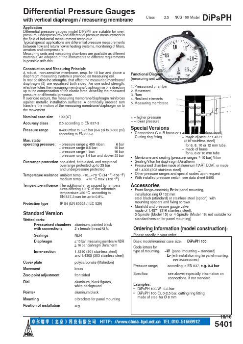
5401Differential Pressure Gaugeswith vertical diaphragm / measuring membraneDiPsPHApplicationDifferential pressure gauges model DiPsPH are suitable for over-pressure, underpressure- and differential pressure measurement in the field of industrial measurement technique.T ypical special applications are differential pressure measurements between flow and return flow in heating systems, monitoring of filters, aerators and compressors.Measuring units and measuring chambers are available as different materials. An adaption of the instruments to different requirements is possible with this.Construction and Measuring PrincipleA robust, non-sensitive membrane, resp. for 10 bar and above a diaphragm measuring system is provided as measuring cell.In rest position the strengths, that effect the measuring membrane/diaphragm (5) are equalised both-sided. An one-sided strength, which switches the measuring membrane/diaphragm in one direction up to the compensation of the elastic force, arises by the measured pressure or differential pressure.If overload occurs, the measuring membrane/diaphragm reinforces against metallic installation surfaces. A centrically ordered ram transfers the motion of the measuring membrane/diaphragm on to the movement.Nominal case size 100 (4")Accuracy class 2.5 according to EN 837-3Pressure range 0-400 mbar to 0-25 bar (0-6 psi to 0-300 psi) according to EN 837-3Max. staticoperating pressure: – pressure range < 400 mbar: 6 bar – pressure range 0.6 bar: 10 bar – pressure range 1 bar: 16 bar – pressure range 1.6 bar and above: 25 bar Overrange protection one-sided, both-sided- and reciprocal overrange protected up to 25 bar and underpressure protectedTemperature resitance ambient temp.: -10...+70 °C (14 °F -158 °F) medium temp.: +70 °C max. (158 °F)Temperature influence The additional error caused by tempera- tures differing 10 °C of the reference temperature +20 °C according to EN 837-3 can be up to 0.8%.Protection type IP 54 (EN 60529 / IEC 529)Standard VersionWetted parts: Pressurised chambers aluminum, painted black with connections 2 x female thread G ¼ Sealings NBRDiaphragm< 10 bar measuring membrane NBR > 16 bar diahragm Duratherm Inner section 1.4310 (301 stainless steel)and 1.4305 (303 stainless steel)Cover plate polycarbonate (Makrolon)Movementbrass Zero point adjustment frontsidedDial aluminum, black figures, white background Pointer aluminum blackMounting3 brackets for panel mounting Position of installationanyClass 2.5 NCS 100 ModelSOrdering Information (model construction):Please specify in your order:Basic model/nominal case size:DiPsPH 100Code letters fortype of mounting: –W (panel mounting = standard) –Er (with installation ring for panel mounting, see accessories)Pressure range: according to EN 837, e.g. 0-4 bar Specifics: see above; especially information onconnections, if not standardExamples:• DiPsPH 100-W, 0-6 bar• DiPsPH 100-Er, 0-2,5 bar, cutting ring fitting made of steel for Ø 8 mmFunctional Diagram(measuring unit with measuring membrane)1. Pressurised chamber 2. Movement 3. Ram4. Resilient elements5. Measuring membrane + = higher pressure – = lower pressure Special Versions• Connections G ¼ B brass or 1.4305 (303 stainless steel); Cutting ring fitting – made of steel or 1.4571 (316 stainless steel) for 6, 8, 10 or 12 mm tube; – made of brass for 6, 8 or 10 mm tube • Membrane and sealing (pressure ranges < 10 bar) Viton • Sealing Viton for diaphragm Duratherm• Pressurised chamber made of aluminum HART COA T , or made of 1.4305 (303 stainless steel)• Other pressure ranges and special scales upon request • With installed pressure switch, see data sheet 5495Accessories• Front flange-assembly Er for panel mounting, installation ring Ø 132 mmsteel black (standard) or stainless steel (option), with mounting spacers and fixing screws • Manifold and pressure gauge valve made of 1.4571 (316 stainless steel),3-Spindle (Model 15) or 4-Spindle (Model 16; not suitable forstandard version for panel mounting)10/10Dimensional data ( mm / inches ) and weights ( kg / lb )NCS a a1b b1b2b3b4c c1c2c3c4c5c6c7D d11004"16.5.65261.021034.061054.13983.86783.07903.545.23.1213.5115.5918 ±0.2.7121.830.8.031.041044.091164.57NG d2d3d4G G1h h1h3h4s SW SW1Weight (approx.)1004"12784.888.31G ¼ female ¼" femaleG ¼ B ¼" BSP823.23773.03863.3920.795.219.7517.671.20 kg2.6 lbs w i t c h p a n e l c u t o u topened openedmeasuring instrumentventilationfunctional diagram。
2000仪表说明书

2105称重显示控制仪使用说明书VER1.0目录第一章前言 (2)1、概述 (2)2、环境参数 (2)3、电源 (2)4、称重传感器 (2)5、主板数字输入端口 (2)6、主板数字输出端口 (2)7、通讯板 (2)8、主要性能 (3)9、主要功能 (3)第二章安装 (5)1、总述 (5)2、安装 (5)3、安全警示 (5)4、接线 (5)5、仪表初始设置 (5)第三章操作明细 (12)1、前面板 (12)2、LED状态指示 (12)3、键盘 (12)4、菜单显示 (12)5、运行显示 (13)第四章菜单 (15)1、主菜单1 (15)2、主菜单2 (18)3、主菜单3 (23)4、主菜单4 (23)5、主菜单5 (28)6、主菜单6 (29)第一章前言1、概述2000系列秤重控制控制器,是以微机为基础的动态皮带秤及配料控制用仪表。
采用人机对话在VFD屏幕上,以中文形式直接显示称重流量、累计有关信息,操作、校准尤为方便。
仪表具有自动零点校准、自动间隔校准、故障报警自动诊断、光隔离输入/输出,标准串口,内置PID控制输出。
2、环境参数1. 储存温度 - 40%—— +70%;运行温度 -10℃—— +50℃;2. 最大相对湿度:95%;3、电源·220VAC+10%—15% 50HZ·保险丝 0.5A·EMI/RFI 滤波器4、称重传感器·仪表提供10VDC,200mA激励电源,可并联4个称重传感器·灵敏度,0.5mV/V-3.5mV/V·最大输入信号33mV·称重传感器屏蔽接地·电缆距离大于60米(不超过900米)时采用激励补偿电路跳线选择本地或远程补偿5、主板数字输入端口仪表主板提供3个可编程输入端口,接收干触点开关信号。
6、主板数字输出端口仪表主板提供3个可编程输出端口,24VDC集电极开路输出,可直接驱动控制继电器。
XINKE AL2000使用说明书

特别注意:
为保证您的利益并使您能够得到及时有效的售后服务,请您认真填写“仪器保修卡”并 将其沿虚线剪下复印后按照我公司联系方式传真或邮寄至我公司。
且不可超过最大使用压力,注意油雾分离器应及时排污!
3.使用方法
3.1 环境要求
务必将测试仪安装在能足够承载仪器的工作台面上,仪器底面安装有四个橡胶地脚,主 要用于防滑、减震和支撑,附件中配有仪器固定安装支架,强烈建议用户加装使用,以免受 到外力作用时,滑落地面损伤乃至摔毁仪器。
安装测试仪时,外围请预留 50mm 以上的空间,以免堵塞散热孔导致仪器内部温度上 升。要在背面预留足够的操作空间,以便连接各种电缆及空压配管。测试仪上部不允许放置 其他物品,尤其是液体,否则有可能倾倒泼溅到仪器内部,导致仪器损坏。
沈阳加金科精密仪器设备有限公司
地址:沈阳市沈北新区正良四路 58 号 电话:024-89738818、89738828
邮编:110136 传真:024-89738618
E-mail: xinke@
产品构成
标准品
型号 AL-2000
如果忽视该类警告中的内容,可能有发生人身事故的危险。
注意: 防止损坏仪器用
如果忽视该类警告中的内容,可能损坏仪器或造成仪器性能的下降。
〔图标说明〕
符号表示注意(包括危险)事项。三角框内画有具体的注意内容。 (左例表示注意高温)
符号表示禁止事项。圆形框内画有具体的禁止内容。 (左例表示禁止拆卸)
IN2000数显面板表说明书

IN2000数显直流电压电流表使用说明书1产品特点:超小型精致模具,全封闭设计,省电液晶显示,时尚美观,宽电压控制芯片,超低功耗,高品质器件,抗干扰佳, 壳体颜色:黑色,蓝色,白色可选。
液晶屏视角:6点,12点可选。
方便阁下多元化选择。
2主要技术指标:1电源:DC5V+5% (其它电源可选) 2功耗W0.6mA 无光 3超量程显示1或者后三位无显示 4工作温度:・10〜60℃湿度:85%以下 5显小字体大小:13*6mm 6测量速率约2.5次/秒准确度:0.2% ±2个字7支持0-20mA/0-10V 等模拟信号输入 8显示±1999 9外形尺寸:48*28* 18mm 建议开孔尺寸:46*26nini 10极性自动识别,自动转换11内置校准电位器12背光效果:蓝色,黄绿色可选带背光电流约50mA3尺寸与接线端子图:信号输入正 信号输入负• —一工作电源负 •工作电源正5应用举例:6注意事项:1仪表为直流供电时.,推荐系统供电电源负与信号负不相连。
2测曷电流时仪表须独立供电,如用户被测信号负与电源负不能分开时,仪表外部须加装DC/DC 隔离模块,否则可能导致烧表测量不准, 跳字等现象。
3测量电压应将表头测量端并联在被测电路中,测量电流应将表头测量端串联在被测电路中(推荐)串联电源低电位端。
4测量电压信号或者测量电流信号,须按照产品的接线图与对应信号连接可靠,并检瓷线路无误再通电。
5使用前,仪表需通电预热15分钟。
6输入导线不易过长,如被测信号输出端较长时请用双绞屏蔽线 7若信号伴随高频干扰,应在线里使用高频过滤器08长时间存放未使用时,请每3个月至少通电一次不小于4小时。
公司专业生产数显电压电流仪表,温度温控仪表,单相三相多功能电力仪表,数显计数器,计时仪,数显转速表,频率表,电阻表,湿度仪表,功率表,变送器,导轨式单三相电能表,承接非标仪表开发生产业务。
IN2000直流 满量程 分辨率输入电阻量程扩展说明电压电流表 士 199.9m V100uV 100MQ (内阻) 1:表格列出量程可以直接信号接入测量,当常用量程:± 1.999V ImV 1 MQ 电流大于2A 以上需外接分流器来扩展量程,± 19.99V lOmV 1MQ 可配2000 A/75mV 分流器来测量2(XX )A 之内 允许输入满 ±199.9V 100mV 1MQ 的大电流.特殊量程可以定制。
新版中分2000说明书

5.1 热导检测器(TCD)......................................................... 27 5.2 氢焰检测器(FID) ..................................................... 30
— I—
第 7 章 操作使用 ................................................... 45
7.1 常用操作项目 .............................................................. 45 7.2 日常开关机操作步骤 .................................................... 48 7.3 操作注意事项 .............................................................. 49 7.4 仪器的保养 .................................................................. 49
1.1 仪器的主要特点
1、 大显示屏中文液晶显示
采用大显示屏液晶点阵汉字显示技术,能同时显示 6-8 行信息, 四路温控、载气流量可同时监视,显示信息量大,操作方便,更符合 操作人员的习惯。
ቤተ መጻሕፍቲ ባይዱ
2、 全微机化操作
采用最新型全集成混合信号单片机控制系统,简化了电路设计, 实现对各路温度参数的设定与控制、检测器控制、流量显示等功能。 大大提高了控制能力和可靠性。
dwyer2000差压表中文说明书

dwyer2000差压表中文说明书摘要:1.Dwyer 2000 差压表概述2.Dwyer 2000 差压表的主要特点3.Dwyer 2000 差压表的工作原理4.Dwyer 2000 差压表的应用领域5.Dwyer 2000 差压表的操作与维护6.Dwyer 2000 差压表的注意事项正文:【Dwyer 2000 差压表概述】Dwyer 2000 差压表是一款高精度的差压测量仪器,适用于各种工业场合,如石油、化工、冶金、电力等。
它能够测量流体中的压力差,为流程控制、生产监测和设备维护提供准确数据。
【Dwyer 2000 差压表的主要特点】Dwyer 2000 差压表具有以下主要特点:1.高精度:采用先进的传感器技术,具有较高的测量精度和稳定性。
2.宽量程:可根据实际需求,选择不同量程的差压表。
3.抗干扰能力强:具有较强的抗电磁干扰和抗射频干扰能力,保证在复杂环境中的稳定测量。
4.耐腐蚀:采用不锈钢材质,具有良好的耐腐蚀性能。
5.易于安装与维护:结构简单,安装方便,便于日常维护。
【Dwyer 2000 差压表的工作原理】Dwyer 2000 差压表的工作原理基于差压传感器。
差压传感器通过测量流体在两个不同位置的压力,计算压力差,从而得到流体的差压值。
当流体通过传感器时,其中一个位置的压力较高,另一个位置的压力较低。
差压表将这两个压力信号转换为标准信号,如4-20mA 或0-10V 等,以供显示、记录或控制。
【Dwyer 2000 差压表的应用领域】Dwyer 2000 差压表广泛应用于以下领域:1.流量控制:通过测量管道中的压力差,可以计算出流速和流量,实现对流量的控制。
2.液位控制:在密闭容器中,通过测量容器内外的压力差,可以判断液位高度,实现液位控制。
3.设备维护:通过对设备内部流体的压力差进行监测,可以发现设备的异常情况,提前进行维护和保养。
【Dwyer 2000 差压表的操作与维护】1.操作:a) 在使用前,检查差压表的表头、传感器和连接管道是否完好。
重型差压式压力表用户手册 型号:SDL720说明书

User ManualHeavy DutyDifferential Pressure ManometerModel SDL720Additional User Manual Translations available at IntroductionCongratulations on your purchase of the Extech SDL720 Pressure Manometer. This devicemeasures gauge and differential pressure in the range of ±29 psi. Supported measurement units are bar, psi, Kg/cm 2, mm Hg, inch Hg, meters of H 2O, inches of H 2O, atmosphere, hPA, and kPA. Logged data readings are stored on an SD card for transfer to a PC. This meter is shipped fully tested and calibrated and, with proper use, will provide years of reliable service. Please visit our website () to check for the latest version of this User Manual, other Translations of this manual, and Customer Support.SafetyInternational Safety SymbolsThis symbol, adjacent to another symbol or terminal, indicates the user must refer to the manual for further information.Meter Description1. P1 Input (positive +)2. P2 Input (negative ‐)3. LCD Display4. HOLD and Backlightkey5. MAX ‐MIN key6. SET and7. RS232 output jack 8. Reset button 9. Power Adaptor jack 10. SD card slot 11. ENTER and LOG key12. Down arrow ▼ key(Press ▼&▲ key at same time to zero meter) 13. Up arrow ▲ / UNIT key(Press ▼&▲ key at same time to zero meter) 14. Power ON ‐OFF keyNotes: Items 7, 8, and 9 are located behind the snap ‐off compartment cover on meter’s right side. Battery compartment, tilt stand, and tripod mount are located on the rear of the instrument.Getting StartedPower ON‐OFF∙Power the meter by pressing and holding the power button for at least 1.5 seconds.∙Press and hold the power button for at least 1.5 seconds to power OFF the meter.∙This meter is powered by six (6) 1.5VDC ‘AA’ batteries or by optional AC adaptor. If the meter will not switch ON please check that fresh batteries are installed in the rear battery compartment or, in the case of the AC adaptor, check that the adaptor is connectedcorrectly to the meter and to an AC source.Display BacklightTo turn the display backlight ON or OFF, press and hold the backlight button for at least 1.5 seconds. The meter will beep when switching the backlight ON or OFF unless the beeper is disabled.Units of MeasureThe currently selected unit of measure is shown below the measurement value on the meter’s LCD. To change the unit of measure, press and hold the UNIT button until the desired unit of measure appears and then release the UNIT button. The meter begins scrolling through the available units of measure (see table below) after the UNIT button has been depressed for at least 1.5 seconds.UNIT DISPLAY INDICATORpsi PSIInch Hg In HgInch H2O In H2OhPA hPAkPA _PABar bArKg/cm2 _g C2mm Hg ‐‐HgMeters H2O ‐t H2OAtmospheres AtPZERO AdjustmentTo null, or zero, the display for a connected sensor, press and hold the up ☐and down ❑arrow keys for at least 1.5 seconds. The meter will show CAL 0 on the bottom left of the screen. Data HoldTo freeze a displayed reading on the LCD, momentarily press the HOLD button (the HOLD icon will appear above the reading). To exit HOLD, press the HOLD button again.Setup ModeBasic settings at a glanceTo view the current configuration of the meter with regard to time, date, and datalogging sampling rate press the SET button momentarily. The meter will now display the configuration in quick succession. If the information is missed on the first try, simply press the SET button again until all of the information is noted.Accessing the Setup mode1.Press and hold the SET button for at least 1.5 seconds to access the Setup menu.2.Press the SET button momentarily to step through the available parameters. The parametertype is shown on the bottom of the LCD and the current selection for that type is shownabove it.3.When a parameter is displayed that is to be changed, use the arrow keys to change thesetting. Press the ENTER button to confirm a change.4.Press and hold the SET button for at least 1.5 seconds to exit the Setup mode. Note that themeter automatically switches out of the Setup mode if no key is pressed within 7 seconds.5.The available Setup parameters are listed below. Additional detailed information isprovided below this list:dAtE Set the clock (Year/Month/Date; Hours/Minutes/Seconds)SP‐t Set the datalogger sampling rate (Hours/Minutes/Seconds)PoFF Automatic power‐off management (Enable or disable the auto‐power offfunction)bEEP Set the beeper sound ON/OFFdEC Set the numerical format; USA (decimal: 20.00) or European (comma: 20,00)Sd F Format the SD memory cardSetting the Clock Time1.Access the dAtE parameter.e the arrow keys to change a valuee the ENTER button to step through the selections4.Press and hold the SET button for at least 1.5 seconds to exit to the normal operation mode(or simply wait 7 seconds for the meter to automatically switch to the normal operatingmode).5.The clock will keep accurate time even when the meter is switched off. However, if thebattery expires the clock will have to be reset after fresh batteries are installed.Setting the Datalogger Sampling Time (Rate)1.Access the SP‐t parameter.2.The sampling rate can be set from ‘0’ seconds (manual log mode) up to 8 hours, 59 minutes,and 59 seconds. (Data lose may occur when logging at a 1 second rate)e the ENTER button to move through the Hours, Minutes, and Seconds digit groups anduse the arrow keys to change the digit values.4.Press the ENTER button to confirm the entry.5.Press and hold the SET button for at least 1.5 seconds to exit to the normal operation mode(or simply wait 7 seconds for the meter to automatically switch to the normal operatingmode).Enabling/Disabling the Auto Power OFF Feature1.Access the PoFF parameter.e the arrow buttons to select ON or OFF. With the Auto Power OFF feature enabled, themeter will automatically switch OFF after 10 minutes of inactivity.3.Press ENTER to confirm setting.4.Press and hold the SET button for at least 1.5 seconds to exit to the normal operation mode(or simply wait 7 seconds for the meter to automatically switch to the normal operatingmode).Set the Beeper Sound ON or OFF1.Access the bEEP parameter.e the arrow buttons to select ON or OFF.3.Press ENTER to confirm setting.4.Press and hold the SET button for at least 1.5 seconds to exit to the normal operation mode(or simply wait 7 seconds for the meter to automatically switch to the normal operatingmode).Numerical Format (comma or decimal)European and USA numerical formats differ. The meter defaults to USA mode where a decimal point is used to separate units from tenths, i.e. 20.00; The European format uses a comma, i.e. 20,00 to separate units from tenths. To change this setting:1.Access the dEC parameter.e the arrow buttons to select USA or EUro.3.Press ENTER to confirm setting.4.Press and hold the SET button for at least 1.5 seconds to exit to the normal operation mode(or simply wait 7 seconds for the meter to automatically switch to the normal operatingmode).SD Card FORMATTING1.Access the Sd F parameter.e the arrow buttons to select YES to format the card (select NO to abort). Note that alldata on the card will be lost if formatting is attempted.3.Press ENTER to confirm selection.4.Press ENTER again to re‐confirm.5.The meter will automatically return to the normal operating mode when formatting iscomplete. If not, press and hold the SET button for at least 1.5 seconds to exit to the normal operation mode.System ResetIf the meter’s keys become inoperable or if the display freezes the Reset button can be used to reset the instrument.∙Use a paper clip or similar item to momentarily press the reset button located on the lower right side of the instrument under the snap‐off compartment cover.∙After pressing the Reset button, switch the instrument ON by pressing and holding the POWER key for at least 1.5 seconds. If using the power adaptor unplug the adaptor and then plug it back in again to power the meter.Max‐Min Reading RecordFor a given measurement session, this meter can record the highest (MAX) and the lowest (MIN) readings for later recall.1.Press the MAX‐MIN button momentarily to access this mode of operation (REC iconappears).2.The meter is now recording the MAX and MIN readings.3.Press the MAX‐MIN button again to view the current MAX readings (MAX icon appears).The readings on the display are now the highest readings encountered since the REC iconwas switched on (when the MAX‐MIN button was first pressed).4.Press the MAX‐MIN button again to view the current MIN readings (MIN icon appears). Thereadings on the display are now the lowest readings encountered since the REC icon wasswitched on (when the MAX‐MIN button was first pressed).5.To exit the MAX‐MIN mode, press and hold the MAX‐MIN button for at least 1.5 seconds.The meter will beep, the REC‐MAX‐MIN icons will switch off, the MAX‐MIN memory willclear, and the meter will return to the normal operating mode.Fittings ConnectionConnect tubing to the P1 (+), P2 (‐), or both input port(s). If both inputs are used (differential mode), the meter displays a positive pressure reading if the P1 (+) pressure is greater than P2 (‐) and a negative reading if P2 (‐) is greater than P1 (+).DataloggingTypes of Data Recording∙Manual Datalogging: Manually log up to 99 readings onto an SD card via push‐button press. ∙Automatic Datalogging: Automatically log data onto an SD memory card where the number of data points is virtually limited only by the card size. Readings are logged at a rate specified by the user.SD Card Information∙Insert an SD card (from 1G size up to 16G) into the SD card slot at the bottom of the meter.The card must be inserted with the front of the card (label side) facing toward the rear of the meter.∙If the SD card is being used for the first time it is recommended that the card be formatted and the logger’s clock set to allow for accurate date/time stamping during dataloggingsessions. Refer to the Setup Mode section for SD card formatting and time/date settinginstructions.∙European and USA numerical formats differ. The data on the SD card can be formatted for either format. The meter defaults to USA mode where a decimal point is used to separate units from tenths, i.e. 20.00. The European format uses a comma, i.e. 20,00. To change this setting, refer to the Setup Mode section.Manual DataloggingIn the manual mode the user presses the LOG button to manually log a reading onto the SD card.1.Set the sampling rate to ‘0’ seconds as described in the Setup Mode section.2.Press and hold the LOG button for at least 1.5 seconds and the DATALOGGER icon willappear on the LCD; the lower portion of the display will show p‐n (n = memory positionnumber 1‐99). Note that if PSI is set as the unit of measure it appears as P51 (where a ‘5’ is used as an ‘S’) in the same area of the LCD where memory locations are shown. This can be disorienting at first.3.Momentarily press the LOG button to store a reading. The DATALOGGER icon will flash andthe beeper will sound (if set to ON) each time a data point is stored.e the ▲ and ▼ buttons to select one of the 99 data memory positions in which to record.5.To exit the manual datalogging mode, press and hold the LOG button for at least 1.5seconds. The DATALOGGER icon will switch off.Automatic DataloggingIn automatic datalogging mode the meter takes and stores a reading at a user‐specified sampling rate onto an SD memory card. The meter defaults to a sampling rate of two seconds. To change the sampling rate, refer to the Setup Mode section (the sampling rate cannot be ‘0’ for automatic datalogging):1.Select the sampling rate in the Setup Mode to a value other than zero.2.Press and hold the LOG button for at least 1.5 seconds. The meter will flash theDATALOGGER icon at the selected sampling rate indicating that readings are now beingautomatically recorded to the SD card.3.If a card is not inserted or if the card is defective, the meter will display EMPTY and exit theDATALOGGER mode. In this case, switch the meter OFF and try again with a valid SD card. 4.Pause the datalogger by pressing the LOG button momentarily. The DATALOGGER icon willstop flashing and the sample rate will display for a short time. To resume logging simplypress the LOG button again momentarily.5.To terminate the datalogging session press and hold the LOG button for at least 1.5seconds.6.When an SD card is used for the first time a folder is created on the card and namedPMA01. Up to 99 spreadsheet documents (each with 30,000 readings) can be stored in this folder.7.When datalogging begins a new spreadsheet document named PMA01001.xls is created onthe SD card in the PMA01 folder. The data recorded will be placed in the PMA01001.xlsdocument until 30,000 readings are reached.8.If the measurement session exceeds 30,000 readings, a new document will be created(PMA01002.xls) where another 30,000 readings can be stored. This method continues forup to 99 documents, after which another folder is created (PMA02) where another 99spreadsheet documents can be stored. This process continues in this same fashion withfolders PMA03 through PMA10 (last allowable folder).SD Data Card to PC Data Transferplete a datalogging session as detailed above in the previous sections. Hint: For thefirst few tests, simply record a small amount of test data. This is to ensure that thedatalogging process is well understood before committing to critical, large scaledatalogging.2.With the meter switched OFF, remove the SD Card.3.Plug the SD Card directly into a PC SD card reader. If the PC does not have an SD card slot,use an SD card adaptor (available at most outlets where computer accessories are sold).4.Power the PC and run a spreadsheet software program. Open the saved documents in thespreadsheet software program (see example spreadsheet data screen below).Spreadsheet data exampleAC Power AdaptorThis meter is normally powered by six (6) 1.5V ‘AA’ batteries. An optional 9V power adaptor is available. When the adaptor is used, the meter is permanently powered and the power button will be disabled.Hose CouplingsThis meter is supplied with a pair of hose couplings. They fit 4.0mm (0.157”) tubing. See diagram on how to connect these couplings to the hose and the meter.Battery Replacement and DisposalWhen the low battery icon appears on the LCD, the batteries must be replaced. Several hours of accurate readings are still possible in this condition; however, batteries should be replaced as soon as possible:∙Remove the two (2) Phillips screws from the rear of the meter (directly above the top of the tilt stand).∙Remove and safely place the battery compartment and screws where they will not be damaged or lost.∙Replace the six (6) 1.5V ‘AA’ batteries observing correct polarity.∙Replace the battery compartment cover with the two (2) Phillips screws.Never dispose of used batteries or rechargeable batteries in household waste.As consumers, users are legally required to take used batteries to appropriatecollection sites, the retail store where the batteries were purchased, or whereverbatteries are sold.Disposal: Do not dispose of this instrument in household waste. The user is obligated to take end‐of‐life devices to a designated collection point for the disposal of electrical and electronic equipment.Other Battery Safety Reminderso Never dispose of batteries in a fire. Batteries may explode or leak.o Never mix battery types. Always install new batteries of the same type.SpecificationsGeneral SpecificationsDisplay Backlit LCD; LCD size: 51 x 37mm (2 x 1.5”)Status indicators Over‐range audible beep and low battery display iconMeasurement Units m Bar, psi, Kg/cm2, hPA, mm Hg, inch Hg, meters H2O, kPA, inchesH2O, ATPAccuracy (Meter) ± (2%FS) at ambient temperature 23°C (± 5°C)Input circuit Differential inputs (P1 and P2)Input Ports Two metal 0.197”(5.0mm), barbed for 0.157" (4.0mm) ID tubing Hose couplings Replacement pair of hose couplings (407915)Sensor Built‐in piezoelectric sensorsDatalogger Sampling Rate AUTO LOGGING: From 1 second up to 8 hours 59 min 59sec. (Data lose may occur when logging at a 1 second rate) MANUAL LOGGING: Set the sampling rate to ‘0’ seconds.Select 1 to 99 locations.Data error number ≤ 0.1% number of total saved dataMemory Card SD memory card; 1G to 16GB sizeData Hold Freeze the displayed readingMemory Recall Record and Recall the Maximum and Minimum readingsDisplay update rate Approx. 1 secondOperating Temperature 0 to 50°C (32 to 122°F)Operating Humidity 85% R.H. max.Auto Power OFF A fter 10 minutes of inactivity (can be disabled)Power Supply Six (6) 1.5 VDC batteries (optional 9V AC adaptor)Power Consumption Normal operation (backlight and datalogger OFF): approx.7mAdcWith backlight OFF and datalogging ON: approx. 25mAdcWith backlight ON add approx. 10mAdcWeight 265g (0.59 lbs.)Dimensions 190 x 68 x 45mm (7.5 x 2.7 x 1.8”)Range/Resolution SpecificationsRange/Units (Max.) Resolution± 2000 mbar 1± 29 psi 0.01± 2.040 Kg/cm2 0.001± 1500 mm Hg 1± 59.05 inches Hg 0.02± 200 kPa 0.1± 2000 hPA 1± 802 inches H2O 0.5± 20.40 m H2O 0.01± 1.974 ATP 0.001ConversionsUseful conversion FactorsFrom To Multiplierin of H2O in of Hg 0.07355in of H2O cm of H2O 2.54mm of Hg in of H2O 0.53524Copyright © 2016 FLIR Systems, Inc.All rights reserved including the right of reproduction in whole or in part in any formISO‐9001 Certified。
压力计量表说明书

0.1 0.2 0.5 0.5 0.5 1 2 5 5 5 10 20 50 50 50 100 200 500 500 1000
Compound – kg/cm2 and bar
Range
Figure interval
–1/0/1.5
0.2
–1/0/3
0.5
–1/0/5
0.5
–1/0/9
1
–1/0/15
50,000 50,000
Compound – (kPa) kilopascal
Range
–100/0/150 –100/0/300 –100/0/500 –100/0/900 –100/0/1500 –100/0/2400
Figure interval
50 50 50 100 200 500
Vacuum – (kPa) kilopascal
30˝ Hg/20 30˝ Hg/40 30˝ Hg/70 30˝ Hg/125 30˝ Hg/215 30˝ Hg/340
Outer scale
30˝ Hg
* 200° Arc
More complete corrosion guide available on our website at .
Minor graduation
in Hg
psi
0.5
0.2
1
0.5
1
1
2
1
5
2
5
2
5
2
5
5
5
5
10
5
Minor graduation
psi
ft H2O
0.5
0.5
0.5
1
0.5
2000系列压差表介绍
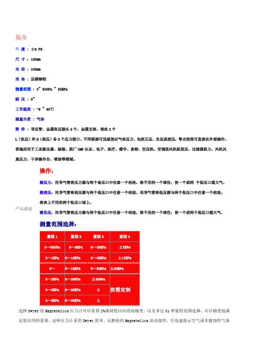
简介精 度 : ±% FS 尺 寸 :120mm 内 径 : 100mm 壳 体 : 压模铸铝测量范围 : 0~ 500Pa ~ 50KPa 耐 压 : 0~工作温度 : -6 ~ 60℃ 测量介质 : 气体附 件 : 导压管、金属取压接头2个、金属支架、堵丝2个L (低压)和H (高压)各2个压力接口。
不同联接可迅速指示气体压力,包括正压、负压或差压;零点校准可直接在外部操作。
普遍应用于工业除尘器、涂装、药厂GMP 认证、电子、医疗、楼宇、食物、空压机、空调送风机组差压、过滤器阻力、风机风扇压力、干净操作台、喷涂等领域。
产品描述选择Dwyer 的Magnehelica 压力计可以获得2%满刻度以内的高精度,以及多达81种量程范围选择,可以精度地满足您应用的需要。
这种压力计采用Dwyer 简单、无磨损的Magnehelica 活动部件,可迅速指示空气或非腐蚀性气体操作:测压力:用导气管将压力源与两个高压口中任意一个相连,将不用的一个堵住;使一个或两 个低压口通大气。
测差压:用导气管将高压源与两个高压口中任意一个相连,用导气管将低压源与两个低压口中任意一个相连; 将表上不用的两个取压口堵上。
测负压:用导气管将压力源与两个低压口中任意一个相连,将不用的一个堵住;使一个或两个高压口通大气。
测量范围选择:的低压-正压、负压(真空)或差压皆可。
2000系列膜片式压差表指示空气、气体和低压--正压、负压或差压精度在2%以内,81种量程范围点击放大尺寸图,标准2000系列Magnehelica压力计(中压和高压型略有不同)标准Magnehelica压力计具有大的易读型4"表盘选择Dwyer的Magnehelica压力计可以获得2%满刻度以内的高精度,以及多达81种量程范围选择,可以精度地满足您应用的需要。
这种压力计采用Dwyer简单、无磨损的Magnehelica活动部件,可迅速指示空气或非腐蚀性气体的低压-正压、负压(真空)或差压皆可。
2000A4型精密数字压力表操作规程
目录目录 (1)1目的 (2)2范围 (2)3设备操作方法 (2)3.1用途 (2)3.2主要技术指标 (2)3.3使用方法 (2)4设备清洁、维护和维修 (3)4.1设备清洁 (3)4.2设备保管 (3)4.3设备维护 (3)4.4设备维修 (3)第 0 页 / 共 2 页1 目的规定了2000A4型精密数字压力表的操作和保养。
2 范围各相关使用部门负责仪器的保养、点检、使用和保管。
3 设备操作方法3.1用途用于普通压力表、压力变送器的校验和检定,也可作为压力基准在实验室及压力仪器生产过程中使用。
3.2主要技术指标1)压力测量范围有:-100~0kPa;0~160kPa;0~600kPa;0~1Mpa;0~1.6Mpa;0~6Mpa;0~10Mpa;0~16Mpa;0~40Mpa;0~60Mpa等。
2)压力测量准确度等级有:0.05%F*S±3个字;0.1%F*S±3个字;0.2%F*S±3个字。
3)正常工作条件A.温度:5~40℃B.湿度:<80%RHC.电源电压:直流4.8~5.6VD.通电预热时间:30minE.参比工作条件。
温度:20±2℃;湿度:<70%RH3.3使用方法1)开机:按下“开关”按钮直至电源通,LCD闪烁显示仪表量程。
2)关机:按“开关”按钮,直至LCD显示“OFF”后熄灭。
3)清零:在压力为零时按“清零”按钮,显示熄灭时松开,显示“00000”;再次按下清零键,则显示非零状态。
4)按下“单位”按钮,显示熄灭时松开,显示单位可自动变换,变换次序为MPa,Psi或Bar。
5)为确保计量准确性,请开机预热10分钟后使用6)使用附带充电器(7.1V充电器)充电,充电灯有红变绿后说明充电完成。
7)电池指示:电源指示符号说明电池的电量状态,当符号显示为空符号时应进行充电。
否则测量将产生误差。
4 设备清洁、维护和维修4.1设备清洁使用干毛巾擦拭设备表面浮尘。
- 1、下载文档前请自行甄别文档内容的完整性,平台不提供额外的编辑、内容补充、找答案等附加服务。
- 2、"仅部分预览"的文档,不可在线预览部分如存在完整性等问题,可反馈申请退款(可完整预览的文档不适用该条件!)。
- 3、如文档侵犯您的权益,请联系客服反馈,我们会尽快为您处理(人工客服工作时间:9:00-18:30)。
2. 安装须知
请确保:待安装表满足测量范围 的要求。 务必保证安装环境温度小于140° F (60°C),安装处压力不超过表的 压力测量量程。 所有标准2000 表都是在垂直状态下进行校准的 ,为此2000表必须垂直安装以保 证所述精度。
3. 安装
表壳安装 在直径为4 1/16"的圆上,钻3个大小相同且等 距离的孔,与表背面的3个孔对应 连接。产品配件包里提供适用的3 个固定用螺钉。
4. 压力连接
正压测量: 将压力管连接到表后面任意一个标有 “high pressure”,即“高压” 的孔,并堵塞另外一个高压孔。 把标有 “low pressure”,即“低压”的两个孔暴露 在大气中。
5. 零校准
在安装后进行零校准。把所 有低、高压孔暴露在大气中,然后 使用表壳下方零校准螺钉调整指针 归零。
安装使用手册
i2000系列
1. 产品特性
压力极限: -20" Hg至15 PSI (0.677 bar至1.034 bar); MP 选项: 35 PSI (2.41 bar); HP 选项: 80 PSI (5.52 bar) 适用介质: 空气及与之兼容的非易燃性气体。 精度: 在21C (70 F)温度时, 2% FS (2000-100Pa 和2000-125Pa:3%; 2000-60Pa:4%) 温度范围: -6.7 至60°C (20 至 140°F) 过程连接: 两对 1/8" NPT内螺纹,即侧面和背面各一对,任 选其一。 表壳:铸铝外壳和丙烯酸表罩。 重量: 1 lb 2 oz (510 g), MP和 HP 2 lb 2oz (963g)
-2-
-1-
安装使用手册
无接缝或嵌入式安装 切下一个直径为4 9/16" 的圆,然后把表嵌入剩余部分的空隙 中,并与适配器连接。利用配件包中 提供的6个螺钉将表固定在适当位置 。
i2000系列
ห้องสมุดไป่ตู้
负压测量: 把压力管连接到表背面任意一个标有 “low pressure” ,即“低压”孔,并堵塞另外一个低 压孔。把标有 “high pressure”,即“高压”的两个孔暴露 在大气中。 差压测量: 把高压管连接到任意一个标有“high pressure”,即“高压”孔上,并堵塞 另外一个高压孔。把低压管连接到任 意一个标有“low pressure”,即“低压”孔上,并堵塞 另外一个低压孔。