PSDB用户手册
bps使用手册.
使用手册目标:掌握 BPS 软件的基本操作流程,以及基本 IP 模块的使用目录:一 . Matlab/simulink建模 (2)1. 在开始栏中打开 Xilinx System Generator ,启动进入 system generator (2)2. 运行‘ bps_new_model’命令,选择 mBEE4,点击 ok (2)3. 保存工作 (3)4. 选择系统配置 (3)5. 添加 IP GPIO Out (4)6. 配置 GPIO Out 参数 (5)7. 添加模块 (5)8. 配置 Counter 和 Slice 参数 (6)9. 添加 Simulink Display 和 Scope 模块 ..................................................................................6 10. 添加相关模块 ......................................................................................................................7 11. 配置相关参数 ......................................................................................................................7 12. 建立 Subsystem. (9)13. 系统进行 Simulink 仿真 ................................................................................................... 10二. Bps 编译综合 (10)1. 打开bps (10)2. 选择 Design rule check ,点击 Run BPS ,检查整个设计是否满足规则 (10)3. 选择 Complete build ,并选择 Fork processes ,点击 Run BPS ,编译工程 .................. 11三. 下载验证 .................................................................................................................................13将配置文件下载到 miniBEE4的 FPGA 中实现功能 ...........................................................131. 使用 FileZilla 将 bin 文件和 cdc 文件上传到远程服务器中 (13)2. 使用 vnc-viewer 进入 Linux 终端,运行 SelectMAP ,将 bin 文件配置到FPGA....... 14四.硬件调试:. (14)1. 使用 VNC 客户端,登陆到 miniBEE4,打开 Xilinx ChipScope Analyzer 软件 (14)2. 将 cdc 文件加入进来 (15)3. 运行查看信号 (15)软硬件协同教育部工程中心过程:一 .Matlab/simulink建模1. 在开始栏中打开 Xilinx System Generator ,启动 matlab R2012a 并进入 system generator 。
db手册

1前言....................................................... 2DB2专有名词解释............................................2.1I NSTANCE(实例) ........................................................................................................................2.2DB2A DMINISTRA TION S ERVER(管理服务器) ...........................................................................2.3C ONTAINER(容器) .....................................................................................................................2.4DRDA .......................................................................................................................................2.5DARI .........................................................................................................................................2.6SPM ...........................................................................................................................................2.7FCM ..........................................................................................................................................2.8ADSM .......................................................................................................................................2.9DCE ........................................................................................................................................... 3DB2编程....................................................3.1建存储过程时C REATE 后一定不要用TAB键 ......................................................................3.2使用临时表...............................................................................................................................3.3从数据表中取指定前几条记录 ...............................................................................................3.4游标的使用...............................................................................................................................3.5类似DECODE的转码操作 (10)3.6类似CHARINDEX查找字符在字串中的位置...........................................................................3.7类似DATEDIF计算两个日期的相差天数................................................................................3.8写UDF的例子.........................................................................................................................3.9创建含IDENTITY值(即自动生成的ID)的表...........................................................................3.10预防字段空值的处理...............................................................................................................3.11取得处理的记录数...................................................................................................................3.12从存储过程返回结果集(游标)的用法 ....................................................................................3.13类型转换函数...........................................................................................................................3.14存储过程的互相调用...............................................................................................................3.15C存储过程参数注意 (13)3.16存储过程FENCE及UNFENCE ...................................................................................................3.17SP错误处理用法 .....................................................................................................................3.18V ALUES的使用..........................................................................................................................3.19给SELECT 语句指定隔离级别.................................................................................................3.20A TOMIC及NOT A TOMIC区别.....................................................................................................3.21C及SQL存储过程名称都要注意长度..................................................................................3.22怎样获得自己的数据库连接句柄 ...........................................................................................3.23类似于ORACLE的N AME PIPE...............................................................................................3.24类似于ORACLE的TRUNCATE清表但不记日志的做法 (14)3.25用CLI编程批量的INSERT........................................................................................................ 4DB2一些不好的限制..........................................4.1临时表不能建索引...................................................................................................................4.2CURSOR不能定义为WITH UR(可以但…) ................................................................................4.3CURSOR ORDER BY以后不能FOR UPDATE ................................................................................4.4程序中间不能自由改变隔离级别 ...........................................................................................4.5UPDATE 不能用一个表中的记录为条件修改另一个表中的记录。
技术服务手册-PS篇(标准版)

第一章
一、特点
1、一体化设计,位置变送器、伺服放大器内装,调校方便。
2、结构简单,体积小巧,重量轻,便于安装维护。
3、采用精密小间隙密封齿轮传动,传动效率高,噪声低,寿命长,稳定性高,无需加油。
X2:执行器电机连接端子,连线方式参考图1。
X3:控制信号输入与位置信号输出端子,该端子标有3、4号的为控制信号输入端子,标有5、6号的为位置信号输出端子,连线方式参考图1。
X5:执行器位置电位器接线端子,连接方式参考图1。在按图示连接方式连接时,应确保执行器的电位器与电机板上端子X0的连接关系如图2所示。
接线如下图:其中X5/1为电机的如下图:
公共端,X5/2为电机开方向的L1
端,X54为电机关方向的L2端。
四、独立位置变送器接线
第四章
一、 限位开关的调整
二、伺服放大板PSAP5调试说明书
1、安全事项
调试过程中不可触摸电路板上导体部分,以防触电。
确保各接线端子正确连接。
2、接线端子介绍
X1:电源端子。
PS+POT+PSMF2DC
开关(24V直流电源)动作模式,输出4--20mA反馈信号
调节型
PS+POT+MSC305+MSC308
调节动作模式,输入/出4--20mA反馈信号
PS+POT+PSAP4C
四、PS反馈齿轮的直径与行程
直径(mm)
H行程(mm)
10.8
H=25(塑料)
db基础操作手册学习教案

Not Pred1
可索引(suǒyǐn)谓词
可索引 Y
注释 ∝代表>,>=,来自,<=,<,但是<>不是可索引的。
Y
在匹配系列中必须是最后的。
Y
仅对一个匹配列
Y
Y
模糊匹配%在后面。
N
模糊匹配%在前面。
N
Col1和col2来自同一个表
N
例如:c1(c1+1)/2
Y
Pred1和Pred2都是可索引的,指相同索引的列
DBHEAP
(LOGBUF,
CATALOG
) CACHE_SZ
Package Cache
Bufferpool
Extended Memory
Sort Heap
UTILITY
HEAP (BACKUP, RESTORE
BUFFER)
Lock List
第3页/共66页
第四页,共66页。
实例(shílì)
第4页/共66页
第18页/共66页
第十九页,共66页。
字符集
Create database db_name using codeset GBK territory zh_CN
第19页/共66页
第二十页,共66页。
模式(móshì)(schema)
模式(móshì)是一组数据库对象的集合,他提供了数据库对象 的逻辑分类
第9页/共66页
第十页,共66页。
连接(liánjiē)到数据库
服务器端配置 设置(shèzhì)db2 profile registry的参数DB2COMM,如: Db2set db2comm=tcpip 设置(shèzhì)实例级参数 Db2 update dbm cfg using svcename 50000 修改该参数,需要重起实例
db pa处理器简明使用方法

dbx PA数字声频处理器简明使用方法一、前面板操作按钮PREV PG 前一页NEXT PG 下一页EQ 均衡器设置。
连续按时可选择输入部分的图示均衡GEQ和输出部分各通道的参量均衡PEQSUBHARMONIC 激励器设置(低频谐波处理)XOVER 分频器设置FEEDBACK 反馈抑制设置COMP/LIMITER 压缩器或限幅器设置DELAY 延时设置PROGRAM 程序模式UTILITY 多用途菜单STORE 程序存储WIZARD “向导”设置,包括SYSTEM SETUP系统设置、AUTO EQ自动EQ和AFS自动反馈抑制二、使用方法1、选择程序打开电源后,旋转DATA数据轮选择程序。
工厂程序FACT不一定符合需要,可在用户程序USER里按所需要的工作方式选择一个程序。
2、系统设置按WIZARD键,灯亮,显示屏显示Sysrem Setup系统设置界面。
按NEXT PG键或数据轮就进入Input Setup输入设置,旋转数据轮,选择MONO单声道或STEREO立体声输入。
再按NEXT PG键,进入GEQ图示均衡设置,旋转数据轮设置为双单声道或立体声应用状态。
再按NEXT PG键,进入Main Speaker主扬声器设置,旋转数据轮,按所用的扬声器型号选择。
如果没有所用的型号,就选择最后的Custom即“用户”。
再一次次按NEXT PG键,就依次进入Sub Speaker低音扬声器和高、中、低音各通道功放型号及其输入电平设置。
如果没有所用的型号,就选择最后的Custom,此时就没有输入电平设置项。
全部设置好以后,再按NEXT PG键,就提示Load New Program加载新程序,这时按一下数据轮,显示Loading……,最后提示Program Loaded!程序已加载,系统设置完成,按PROGRAM退出系统设置。
3、调整输入级系统均衡器(手动方式)按调试系统均衡的常规接好频谱仪。
按EQ键,灯亮,显示屏显示图示均衡界面,旋转数据轮选择ON。
DB-RAD (PLUS) BATTERY SERIES 70 - 4.000 Nm 用户手册说明书

- INNOVATION DRIVEN PERFORMANCEDB-RAD (PLUS) BATTERY SERIES 70 - 4.000 NmUser manual for:• DB-RAD (PLUS) 700-2• DB-RAD (PLUS) 1400-2• DB-RAD (PLUS) 2000-2• DB-RAD PLUS 4000-2Table of contents1. General instructions2. Assembly3. Setting torque3.1 Setting direction of rotation3.2 Operating the torque wrench4. User interface4.1 Main Screen4.2 Main Menu4.3 Error display screen4.4 Torque PLUS Angle function (DB-RAD PLUS only)5. Battery5.1 Battery pack faults6. Battery charger6.1 Removing and inserting the battery pack7. Movement of the reaction arm7.1 Installing the reaction arm7.2 Reactie arm height7.3 Reaction arm foot7.4 Reaction point8. Safety9. Warranty9.1 New tool warranty9.2 Repaired tool warranty10. ContactFigure 1Weatherproof case Digital B-RAD torque wrench Li-Ion battery packStandard reaction armBattery charger1. General instructionsCAUTION: After long durations of continuous use, the Digital B-RAD case will become hot. To avoid personal injury it is recommended to use the tool in short intervals. This allows cooling between use,and will prevent the case from becoming too hot to handle.NOTE: Do not operate the tool before reading these instructions. If breakdown, malfunction or damage occurs, do not attempt to repair, please contact RAD Torque Systems B.V. immediately.RAD battery torque wrenches are reversible, non-impacting, torque controlled tightening tools and must always be operated with the following:• Fully charged battery• Impact sockets with locking pin and o-ring • Proper reaction arm with retaining ring.• The intended use of the Digital B-RAD torque wrench is for commercial and industrial bolting applications.• Do not operate the Digital B-RAD torque wrech before reading and understanding this user manual and noting the safety notices displayed on the Digital B-RAD torque wrench and throughout this manual.• Only qualified personnel with training in the safe operation of torque tooling and the Digital B-RAD torque wrech should attempt the installation, operation and diagnosis of the Digital B-RAD torque wrech.• The Digital B-RAD torque wrech is connected to high voltage power and consists of external rotating parts. Improper training and use can cause serious or fatal injury.• Do not disassemble or attempt to repair the Digital B-RAD torque wrench; doing so will void warranty. If breakdown, malfunction or damage occurs and the Digital B-RAD torque wrench fails to operate correctly, contact RAD Torque Systems B.V.• The Digital B-RAD torque wrench should only be used if environmental storage and operation specifications have been met.• Do not operate the Digital B-RAD torque wrench in explosive atmospheres, including, but not limited to, the presence of flammable liquids, gases or dust. The Digital B-RAD torque wrech creates sparks which could ignite these substances.• Do not expose the Digital B-RAD torque wrench to wet conditions. Water in the Digital B-RAD torque wrech will cause damage to the tool and increase the risk of electric shock.• After long durations of use, the Digital B-RAD torque wrech will become hot. It is recommended to use the tool in short intervals and allow for cooling between uses to prevent injury to the operator or damage to the Digital B-RAD torque wrench.• While operating the Digital B-RAD torque wrench, always wear safety goggles and keep all body parts clear of moving parts and the reaction arm contact point.•Never exceed the Mmximum torque of the Digital B-RAD torque wrench. Failure to comply will result in void warranty.The Digital B-RAD torque wrench has been calibrated by a qualified calibration technician; calibration must be done by a qualified calibration technician. Improper calibration can cause damage to the torque wrench and joint.NOTE: These torque wrenches contain metal components that can be dangerous in hazardous areas.3. Setting torqueSet torque by using the up or down arrow on the LCD display. Once this is done, select forward or reverse and you are ready to work when you depress the trigger.2. Assembly1. Make sure the battery is fully charged2. Slide in the battery pack until it engages3.Fasten and secure the reaction arm on the jagged side of the gearbox with the retaining ringRotational direction switchTool triggerLithium-ion batteryBattery release buttonBattery indicator lightsDB-RAD torque wrenchLCD display with access to menus and controlsFigure 23.1 Setting direction of rotationOnly operate the rotational direction switch and transportation switch when the motor is at standstill, seeFigure 3.Figure 3Right setting = Tightening Left setting = LooseningCentral setting=Transportation position3.2 Operating the torque wrench• Use only suitable and proper impact sockets.• The handle can be rotated for ease of installation.• The reaction arm is placed against a solid reaction point before the trigger is pulled. This preventsmovements of reaction arm.• Check that the desired target torque is selected on the display screen.• Press the trigger, the trigger can be released at any time to stop the tool and cancel the torque cycle. • When the tool stops moving the peak torque result will be displayed on the screen. The results willremain displayed for 10 seconds, or until the tool is reversed or a new torque cycle starts.• When the tool reaches the desired torque, the torque wrench will automatically stop.• Once “Pass” or “Fail” has been displayed the tool is ready to perform another torque.WARNING: Keep your hand and body parts clear of the reaction arm and barrel when the tool is in operation.4. User interfaceThe Digital B-RAD offers a user friendly LCD interface with push button navigation.4.1 Main Screen67010TARGET NMPASS READY REVERSEFAILPRESET1Navigate (Row)Set torqueTarget AngleDB-RAD PLUS onlyTorque unit Tool modelNavigate (Column)Preset Status Tightening LooseningSuccessful torque cycle Unsuccessful torque cycleNOTE! Be sure to hold the push button press down for a duration of 1 second. This will ensure that the button was properly registered.Lock/Unlock Indicator Figure 4PRESETSelect pre-defined target torque values.SAVEModify pre-defined preset values.HARD JOINTAllows to operate on a joint with a joint rate of less than 10°.LOCKPassword protection for three user levels: basic, intermediate and advanced.When activated, a “lock” icon will appear at the top of the screen.UNITSSwitch between FTLB and Nm.SETUPThis option contains the Calibration mode and Angle mode (DB-RAD PLUS only) and will only be displayed in advanced lock level.INFOThis option contains the tool info, last result, life cycles, maintenance cycles, and zero maintenance.EXITReturn to main screen.To activate the main menu simply hold down the “select” button from the main screen, see Figure 5. Use the “up arrow” button and the “down arrow” button to highlight the desired menu option and press the “select” button to select the menu option.4.2 Main MenuPRESET SAVEHARD JOINT LOCK UNITS SETUP INFO EXITFigure 55.1 Battery pack faultsWarning indicator stays onThe battery pack is not being charged. The temperature is too high or too low. If the temperature of the battery pack is between 0–49 degrees Celsius, the charging process begins automatically.Warning indicator flashes onThe battery pack is defective, remove from charger immediately.The battery fails to charge, contacts may be dirty. Remove the battery pack, clean the contacts and replace the charger.NOTE: In the case of prolongued activity of electromagnetic disturbances, the battery charger ends the charging process prematurely for safety reasons. Remove the plug and plug in again after 2 seconds.Lithium-ion battery chargers are to be used exclusively for charging RAD 18V Lithium-ion battery packs with the maximum capacity of 5.2AH.5. BatteryWarning!Warning!Warning!Warning!Warning!Warning!Before initial use, check that the voltage and frequency stated on the charger’s rating plate match the figures for your own electrical supply.Unplug charger immediately if the cable or charger is damaged. Unplug immediately if any sign of smoke or flames.To reduce risk of injury, charge only rechargeable RAD batteries, other types of batteries may burst causing personal injury and damage.Do not submit the casing to impact or drill into the casing. Do not throw battery packs or charger in fire or immerse in water. Keep battery packs dry. Do not use any damaged or deformed battery packs.RAD chargers should only be operated between 0-49 degrees Celsius. Keep away from moisture.Slightly acidic, flammable fluid may leak from defective Li-ion battery packs. If battery fluid leaks out and comes into contact with your skin, rinse immediately with plenty of water. If battery fluid leaks and comes into contact with your eyes, wash them with clean water and seek medical treatment immediately.4.3 Error display screenThe tool could experience some malfunctioning, when this occurs an error message will be displayed on the display screen. The error messages could be one of the following:• STALL = Tool has detected high torque at start up• HI CURR = Tool has detected high current during wind-up • NO CURR = Tool has not detected current during wind-up•LO BATT=Tool has detected a low battery voltage during wind-up4.4 Torque PLUS Angle function (DB-RAD PLUS only)The Torque PLUS Angle function controls the angle, in degrees, that the Digital B-RAD PLUS will rotate after the target Torque is reached. If the Digital B-RAD PLUS detects that the Angle produces a torque greater than the tool’s maximum torque capacity, the Torque and Angle cycle will fail and the tool will stop moving.Note: To prevent the battery from draining, always remove battery from tool before storage.6. Battery chargerBefore initial use, check that the voltage and frequency stated on the rating plate match the figures for your own electrical supply and check that the ventilation slits are clear. Minimum clearance from other objects is 5 centimeters.1. Connect to electrical supply, the red and green indicator lights up for approximately 1 second.2. Once the self test is completed, the indicator lights are off.3. Insert the battery pack into the charging shaft socket; push it to the back until it engages.4.Charge the battery pack before use. Only once it has been charged and discharged five charging cycles does the battery pack reach its full charging capacity. You may store charged Lithium-ion battery packs and recharge them after an interval of no more than six months.6.1 Removing and inserting the battery packRemoval: Press in the release button and remove the battery pack.Inserting: Slide in the battery pack until it engages.7. Movement of the reaction armFigure 6Reaction pointClockwise operationCounter clockwise operation7.1 Installing the reaction armEnsure the reaction arm and retaining ring are installed securely to hold the reaction arm in place. Make sure the reaction arm is in contact with a solid reaction point before you operate the tool. When the tool is in operation the reaction arm rotates in the opposite direction to the output square drive and must be allowed to rest squarely against a solid object or surface adjacent to the bolt to be tightened, see Figure 6.WARNING: In use, this tool must be supported at all times in order to prevent unexpected release in the event of a fastener or component failure!Warning beepIn the case of a too high operating temperature, the battery will give a loud beep tone. The Lithium-ion battery should be disconnected immediately to cooldown. The Lithium-ion battery can be used again if it is cooled down.Afbeelding 9AAfbeelding 9BAfbeelding 9C✔✘✘NOTE: Improper reaction will void warranty and can cause premature tool failure.7.2 Reacti on arm heightEnsure the height of the socket is even with the height of the reaction arm as seen below in Figure 7A. The height of the socket cannot be shorter or higher than the height of the reaction arm as seen below in Figure 7B and 7C.Figure 7AFigure 7BFigure 7C✔✘✘WARNING: Always keep your hand and body parts clear of the reaction arm and barrel when the tool is in operation, see Figure 9C.7.3 Reaction arm footEnsure the foot of the reaction arm aligns with the length of the nut as seen in Figure 8A. The length of the foot cannot be shorter or longer than the nut as seen in Figure 8B and 8C.Figure 8AFigure 8BFigure 8C✔✘✘7.4 Reaction pointEnsure the reaction arm reacts off the middle of the foot as seen in Figure 9A. Do not react off the heel of the reaction foot as seen in Figure 9B.Please contact RAD Torque Systems B.V. or your local RAD authorized distributor for custom reaction arms.8.SafetyRAD tools are developed for tightening and loosening threaded fasteners using very large forces. For your safety and that of others, warning labels and attention labels are prominently attached to the torque wrench and its accessories.NOTE: Make sure you observe the directions on the warning labels at all times.RAD tools have been designed with safety in mind however, as with all tools you must observe all general workshop safety practices, and specifically the following:• Before using your new tool, get familiar with all its accessories and how they work• Always wear safety goggles when the tool is in operation• Make sure the reaction arm is in contact with a solid contact point before you operate the tool• Keep your body parts clear of the reaction arm and the contact point• Make sure the reaction arm snap ring is securely in place to hold the reaction arm or blank in place. RAD tools are safe and reliable. Not following precautions and instructions outlined here can result in injury to you and your fellow workers. RAD Torque Systems B.V. incorporated is not responsible for any such injury.9. Warranty9.1 New tool warrantyAny new tool branded with the RAD name and purchased from RAD Torque Systems B.V., or through one of its authorized distributors or agents, is warranted to the original purchaser against defects in materials and workmanship for a period of twelve (12) month from the date of delivery to the end user. This guarantee is valid until fifteen (15) months after the original calibration date.Furthermore, the warranty conditions determine that no warranty applies if:1. The defect, wholly or partly, is due to unusual, inappropriate, improper or careless use of the product;2. The defect, wholly or partly, is due to unusual, is due to normal wear and tear or lack of propermaintenance;3. The defect, wholly or partly, is due to unusual, is due to installation, assembly, modification and / orrepair by the customer or by third parties;4. The product altered, modified, used or processed is;5. The product is transferred to a third party;6. RAD Torque Systems B.V. has abtained the product, wholly or partly, from a third party, and RADTorque Systems B.V. can not claim compensation under warranty;7. RAD Torque Systems B.V. in manufacturing of the product raw materials, and suchlike has used onthe instructions of the customer;8. The product has a small deviation in it’s quality, finishing, size, composition and suchlike, which is notunusual in the industry or if the defect was technically unavoidable;9. The customer has not fulfilled all obligations under the agreement promptly and correctly towards RADTorque Systems B.V..9.2 Repaired tool warrantyAfter the warranty has expired a three (3) month warranty applies to the original purchaser against defective in material or workmanship or both from the date of repair.To qualify for the above mentioned warranties, written notice to RAD Torque Systems B.V. must be given immediately upon discovery of such defect, at which time RAD Torque Systems. will issue an authorization to return the tool. Freight costs must be paid in advance. When returning a tool, the reaction arm/s being used with the tool must also be returned.For the latest warranty terms, please see our sales conditions on our website www.radtorque.nl.10. ContactRAD Torque Systems B.V.Zuidergracht 193763 LS SoestPhone: +31(0) 35-5882450Website: www.radtorque.nlMININGOIL & GASWINDPOWERAEROSPACEPETROCHEMICALMANUFACTURINGCOMMERCIAL VEHICLE INDUSTRYMASTER DISTRIBUTOR FOR EUROPE, MIDDLE EAST AND NORTH AFRICA:RAD TORQUE SYSTEMS B.V.ZUIDERGRACHT 193763 LS SOESTTHE NETHERLANDSPHONE.: +31 (0)35 - 5882450E-MAIL: INFO@RADTORQUE.NLSALES@RADTORQUE.NLH SUPPORT@RADTORQUE.NLTECWWW.RADTORQUE.NL。
PSCAD使用手册(中文版)
PSCAD简明使用手册Chapter 1: EMTDC/PSCAD简介 (1 1.1 功能 (11.2 技术背景 (11.3 主要的研究范围 (11.4 目前应用情况 (21.5 各版本限制 (31.6 目前最新版本:PSCAD 第四版 (3 Chapter 2: 安装及License设置 (42.1 安装 (42.2 License设置 (6Chapter 3: PSCAD工作环境 (93.1 术语和定义 (93.1.1 元件 (93.1.2 模块 (103.1.3 工程 (103.2 各工作区介绍 (103.2.1 工作空间窗口 (103.2.2 输出窗口 (143.2.3 设计编辑器 (163.3 工作区设置 (163.4 在线帮助系统 (18 Chapter 4: 基本操作 (194.1 工程 (194.2 元件和模块 (224.2.1 元件 (224.2.2 模块 (254.3 常用工具栏及快捷键 (25 4.3.1常用工具栏 (254.3.2快捷键 (27Chapter 5: 在线绘图和控制 (29 5.1 控制或显示数据的获取 (29 5.2 图形框 (305.3 图、曲线及轨迹 (315.4 在线控制器及仪表 (345.5 几种特殊表计 (365.5.1 XY绘图 (365.5.2多测计 (385.5.3相量计 (39参考文献 (41Chapter 1: EMTDC/PSCAD简介Dennis Woodford博士于1976年在加拿大曼尼托巴水电局开发完成了EMTDC 的初版,是一种世界各国广泛使用的电力系统仿真软件,PSCAD是其用户界面,PSCAD的开发成功,使得用户能更方便地使用EMTDC进行电力系统分析,使电力系统复杂部分可视化成为可能,而且软件可以作为实时数字仿真器的前置端。
可模拟任意大小的交直流系统。
操作环境为:UNIX OS, Windows95, 98,NT等;Fortran 编辑器;浏览器和TCP/IP协议。
PS模块配置手册

目录Part 1: 硬件环境和文档更改记录 (4)Part 2:企业结构 (5)2.1 Enterprise structure graphics (5)Part 3: PS module (7)3.1 Activate project management in controlling area OKKP (7)3.2 Settings for Operative Structure WBS (8)3.2.1 Define project coding mask OPSJ (8)3.2.2 Create project types for WBSE (9)3.2.3 Define priorities for WBSE (9)3.2.4 Create project profile OPSA (9)3.2.5 Specify persons responsible for WBSE OPS6 (12)3.2.6 Define field selection for WBS OPUJ/ OPUK (12)3.2.7 Create user-defined fields for WBSE OPS1 (13)3.2.8 Other setting for WBS (14)3.2.8.1 Validation (14)3.2.8.2 Enhancement (16)3.3 Settings for Operative structure - Network (16)3.3.1 Maintain network types OPSC (16)3.3.2 Specify network parameters for network type OPUV (17)3.3.3 Define control key OPSU (18)3.3.4 Maintain network profile OPUU (20)3.3.5 Set up Number ranges for network CO82 (22)3.3.6 Define and assignment change profile (22)3.3.7 Define screen selection for default work center (23)3.3.8 Define Work center usage for PS (24)3.3.9 Define fields selection for networks (25)3.3.10 Assign network profile to project profile (25)3.4 Basil Settings for Milestone (25)3.4.1 Define milestone usage (25)3.4.2 Define Selection Profiles (26)3.5 COST (26)3.5.1 Specify default for project definition object class (26)3.5.2 Specify default for network header object class (26)3.5.3 Define value category and assign costE to value category (27)3.5.3.1 Define value category (27)3.5.4 Cost planning (27)3.5.4.1 Create/ change planning profile OPSB (28)3.5.4.2 Assign plan profile to project profile (29)3.5.4.3 Easy cost planning (29)3.5.4.3.1 Define CO versions for easy cost planning (29)3.5.4.3.2 Create cost variant - OKKT (29)3.5.4.3.3 Assign plan profile to cost variant (31)3.5.4.3.4 Define cost component structure (31)3.5.4.4 Automatic costing in Network/activity (38)3.5.4.5 EXECUTION SERVICE (39)3.6 Budget (40)3.6.1 Maintain Budget profile OPS9 (40)3.6.2 Stipulate default budget profile for project definition (41)3.6.3 Define Tolerance limits (41)3.6.4 Specify Exempt cost elements OPTK (41)3.7 Automatic and periodic Allocation (42)3.7.1 Field control for funds commitment (42)3.7.2 Check number range for CO document (42)3.8 Revenues and Earnings (42)3.9 Payments (43)3.9.1 Commitment item (43)3.10 Dates (43)3.10.1 Specify parameters for network Scheduling OPU6 (43)3.10.2 Define parameter for WBS scheduling (44)3.10.3 Assign WBS scheduling profile to project profile (45)3.11 Resource (45)3.12 Materials (45)3.12.1 Define procurement indicators for material component OPS8 (45)3.12.2 Monitoring dates (46)3.12.2.1 Define events (46)3.12.2.2 Assign reference dates to events (46)3.12.2.3 Define status (47)3.12.2.4 Define profile for monitoring dates (47)3.12.3 PROMAN project-driven production and procurement management (48)3.12.4 Available check (48)3.12.5 BOM Transfer (48)3.12.6 Control of Sales-order-related prodution (49)3.13 Confirmation (49)3.13.1 Define confirmation parameters OPST (49)3.14 Project Version (51)3.14.1 Define version profile OPTS (51)3.15 Information system (52)3.15.1 Define project view OPUR (52)3.15.2 Define database selection profiles OPTX (53)3.15.3 Define overall profiles for information system OPSM (53)5.5 PS模块增加配置 (58)5.5.1 Change planning profile for planned costs and revenue OPSB (58)5.5.2 Maintain Component Structure OKTZ (58)5.5.3 Commitment Item and fund commitment (59)5.5.3.1 Create Commitment Item FMCIA (59)5.5.3.2 Create and assign commitment items FIPOS (59)5.5.3.3 Check the Assignment (59)5.5.3.4 Commitment item test CJ48 OF32 (60)5.5.4 Automatic and periodic allocations (61)5.5.4.1 Edit Settlement cost elements KA06 (61)5.5.4.2 Create allocation structure (62)5.5.4.3 Create PA transfer structure KEI1 (62)5.5.4.4 Create Settlement Profile and assign to Project profile (63)5.5.4.5 Define strategies for determining settlement rules (64)5.5.5 Result Analysis (65)5.5.5.1 Edit results analysis cost elements KA06 (65)5.5.5.2 Maintain results analysis keys OKG1 (65)5.5.5.3 Maintain results analysis versions OKG2 (65)5.5.5.4 Define valuation methods for results analysis OKG3 (67)5.5.5.5 Define Line IDs (69)5.5.5.6 Define assignments for results analysis OKG5 (69)5.5.5.7 Define Update for results analysis OKG4 (70)5.5.5.8 Define posting rules for settlement to accounting (70)5.5.5.9 Specify default results analysis keys for project definition (71)Part 1: 硬件环境和文档更改记录Part 2:企业结构2.1 Enterprise structure graphicsIn this section, we define the enterprise structure and the relationships between. According to different function module, three structures had been set up, which are:Company code and plantPlant, Purchasing organization, purchasing group and storage locationsCompany code, Sales organization, Distribution channel and DivisionPart 3: PS moduleA classic set of PS business settings will be implemented in this section.Many settings can be directly used because PS module is org. independent. That isthe extreme difference compared to most of other modules in R3 system.SAP library divided sap PS module into several parts, such as structure, cost, process, simulation etc. So, this frame is extended in this document.The PS configuration are subdivided intoPart no Sub-ContentsA-PS- Structure WBS, Network, Planning Board and Milestone.B-PS-Cost Easy cost planning, structure based manually cost planning, Automatic costingfor general cost activitiesC-PS-Payment and Revenue Planning profile, Commitment itemsD-PS-Dates Parameters for Network and WBS schedulingE-PS-Resource Work center used in PS moduleF-PS-Materials Material procurement, ProMAN, Monitoring dates, BOM transfer, ATP, Controlof sales-order-related productionG-PS-Confirmation Confirmation parameterH-PS-Versions Version profileI-PS-Information system Status Selection profile, DB profile, Overall profileJ-PS-Process3.1 Activate project management in controlling area OKKPIMG- Project system – Cost – Activate project management in controlling areaStep 1select controlling area AAA0 and double click Activate components/ control indicator,Step 2 create new entry and save.To 9999 is determined by system and can not be input and changed.Tips, notificationsJust like other module, this step is the proven of PS operating for onecontrolling area.Fisal year The To fisal year is 9999. This fields can not be changed and input. 3.2 Settings for Operative Structure WBS3.2.1 Define project coding mask OPSJIMG- Project system- Structure –work breakdown structure –project coding mask –define project maskSteps Delete existing coding mask. Enter new coding mask, keep the status lck and lKs indictor uncovered.Tips, notificationsNumber or charagcter coding maskIt’s so weared that you can create project definition only includs number or character even if you have not define coding mask for them.Relationship between XX and 00If you define coding mask with XXX, you still use 000 to cover it in instance. But you can not do that by contrast.3.2.2 Create project types for WBSEIMG-Project system – Structure – operative structure – WBS – Create project types for WBSETips, notificationsUse Auth. Control, statstics, substitution etc..3.2.3 Define priorities for WBSEIMG-Project system – Structure – operative structure – WBS – Define priorities for WBSE3.2.4 Create project profile OPSAIMG-Project system – Structure – operative structure – WBS – Create project profile1. Control TAB2. Organization TAB3. Plg board/ dates4. Controlling TABTips, notificationsUse Project profile specify almost all important characters,profiles, parameters for the project. It is also a meanningfulindex of PS module.Notice Many profiles and parameters, such as costing sheet,network profile, settlement profile etc. , are not assigned duringthis phase due to not been defined. In the process below will bedefined and assigned.Create another project profile V for internal constructionproject in the same way. Differences are that V can has manyroots and the project type is V.3.2.5 Specify persons responsible for WBSE OPS63.2.6 Define field selection for WBS OPUJ/ OPUKTips, notificationsUse The definition here can not be conflicted whit the parametershas been maintained in Project profile.The same rules will be effect when you define fieldsselection for WBS element, network, orders or etc.Settings Default setting is input, and u can change that status to req,disp or hide.The field selection for WBS element is defined as3.2.7 Create user-defined fields for WBSE OPS1Tips, notificationsUse To specify the user fields displayed in USER FIELDS for WBSE. Settings Just modify the profile 0000001 due to having assigned user fieldprofile 0000001 to project profile.The layout of this definition is in the details screen of WBS elements.3.2.8 Other setting for WBSSub-StructureValidation To set up rules to check the information in the instanceproject is right or not.substitution To set up rules to make the information in the instancesubstitute automatically.Enhancement for project defin and wbs element Is more useful than user-field. You can define 255 userfields to enhance the project information.3.2.8.1 ValidationStep 1Create New substitution and enter the nameStep 2 Create and save new prerequisiteStep 3Create and save new substitutionsStep 4Create user exit if requiredThe mode pool is RGGBS000, and you can create own user exit and corresponding form in it, then draw the user exit in the substitutions.Step 5The same method to define ValidationNotices and ExplanationsUse The substitution defined above is to set the field project typefor WBS element to W automatically if the project profile is equalto W.About user exit RGGBS000is default program for this usage. Anotherstandard program called fgbbgd00 is called here, which definesall standard types used in your system. A subprogram offgbbgd00 and RGGBS000 is shown as follows.1.DATA: be_wflo LIKE be_subrule VALUE 'W' ,be_such LIKE be_subrule VALUE 'S' ,2. DATA: BEGIN OF exits OCCURS 50,name(5) TYPE c,param LIKE c_exit_param_none,title(60) TYPE c,END OF exits.exits-name = 'U200'.exits-param = c_exit_param_field.exits-title = text-200.APPEND exits.FORM u200 USING e_rmvct TYPE bseg-bewar.PERFORM xref_to_rmvct USING bkpf bseg 1 CHANGING e_rmvct.ENDFORM.The standard user exit in project system CMOD3.2.8.2 Enhancement3.3 Settings for Operative structure - Network3.3.1 Maintain network types OPSCIMG- Project system – Structure – Operative Structure – Network –Settings for networks –Notices and ExplanationsUse Auth. Check; Different number range; Different business;Different settlement.IMM Rel. The network will be released when you create it if you setthis indicator for the network profile.3.3.2 Specify network parameters for network type OPUVIMG- Project system – Structure – operative structure – network – settings for network –specify network for network type.Step 1 , Delete the existing parameter for the target plantsStep 2, Create new records for the plant and assign the right network type for these plant.Step 3, The same way to create network parameters for Plant AAA1.Notices and ExplanationsStrategy Settlemt strategy for network which is defined in automaticsettlement for network.Defult Rule Specified by system and can not changeCost variant Act./ Plan Use default value PS02/ PS03 defined in Automatic costingin network/ activates;There are three types of cost variant in PS.◆For Unit costing in network auto.◆For costing in network auto.◆For Easy cost planning and manually costplanning in WBSNotices and ExplanationsActvtyAcctAsgn. Indicator The cost will settle to upper WBS element if you set thisindicator. Or else, the cost will settle to network header and thento the upper WBS element of network header.This indicator will take effect to control how the costwill be settled with the Header assigned/ Act. Assignedindicator in project profile and the settlement rules fornetwork and WBS elements.Change XX indicator If these indicators are set, the changes of correspondingobject will be record by system.The definition and assignment of change profile will beillustrated later.3.3.3 Define control key OPSUIMG- Project system – Structure – Operative structure – Network – Settings for networkControl Key Description Main charactersWK01Internal process CNF Req.WK02 Internal process Possible CNFWK03 External process CNF Req.WK04 External process CNF Req. – ServiceWK05 General cost activity3.3.4 Maintain network profile OPUUIMG- Project System – Structure – Operative Structure – Network – Settings for Networks- Maintain network profileNetwork TABGraphic TABActivities TABNoticesGraphic Use default settingsParameters Parameters, including procurement, field key, version profile willbe defined and assigned laterNoticesOrg. conflict The conflication of organization assignment will be be warning inthe configuration process, but will cause interruption in thebusiness process. Example, Purchasing org. can be assigned toother plants which has not been defined in Enterprise Structurepart.3.3.5 Set up Number ranges for network CO82IMG- Project system – Structure – Operative Structure – Network – Settings for networks – set up number ranges for network.Step 1 Choose edit group buttonStep 2 Create new group for Network type WK01Interval is from 90001 to 99999Step 3 Assign Order type WK01 to Group3.3.6 Define and assignment change profileIMG- Project system- Structure – Operative Structure – Network – Define change profileNoticesD on’t delete manuallyCan not delete manuually add object automaticallyadded objectsAssignment Must assignment change profile to network profile. It seem likethe common ways in SAP system to control message when userchange some objects. Change documents, change profiles etc3.3.7 Define screen selection for default work centerIMG- Project system – Structure – Operative structures – network – Work center –Define screen selection for default work center3.3.8 Define Work center usage for PS1. Use the default settings work center categories 0006 and usage 009 for project work center.2. Maintain data for default work centerIMG- Project system –Structure –Operative structures –network –Work center –Maintain data for default work center.Basic data settingsNoticesCapacities/ scheduling/ costing Will be configed in PP module. Technically, the work center in PS module can act as the work center in PP module. It also can collect cocst/ capacities for activites and users can also schedul the network activies based on the time set in work center.3.3.9 Define fields selection for networksIMG- project system – structure – operative structure – network – user interface settings- define fields selection for networksFor network header, WBS element must be input, which means network header must be assigned to a WBS element.Default settings for network overviewDefault settings for network detail. Modify work center3.3.10 Assign network profile to project profileIMG- Project System- Operative structure- WBS – Create Project profileIn the plg board/ dates screen3.4 Basil Settings for Milestone3.4.1 Define milestone usageIMG – Project system – Structure – Operative structure – Milestones- Define milestone usageDefine four milestone usage for down payment billing, partials billing, final billing, keypoints in project processing.QuestionWhat is corresponding configuration in SD billingmodule, and how it used in milestone.3.4.2 Define Selection ProfilesIMG- Project System –Structure –Operative Structure- Milestones- Define Selection ProfilesStep 1 Create new selection profileStep 2 Create selection rulesThe definition above means only milestones with CNF and not TECO will be selected. Exp. CN41, choose the status selection profile3.5 COST3.5.1 Specify default for project definition object classIMG- Project system –costs –object class default values- specify default for project definition object classThe values has exist because it has been maintained in project profile3.5.2 Specify default for network header object classIMG- Project system –costs –object class default values- specify default for networkheader object classThe value has exist because it has been maintained when we define network type.NoticeUse For Statistics purpose3.5.3 Define value category and assign costE to value category不知道干什么用的,看1000的设置,跟挣值分析有关,先定义好,以后研究。
DB使用说明书
“深呼吸”系统Deep-Breath System使用说明书Instructions感谢您购买艾尔产品!Thank you for purchasing a AIR product.在使用本产品之前,请务必先仔细阅读本使用说明书。
请务必妥善保管好本书,以便日后能随时查阅。
请在充分理解内容的基础上,正确使用。
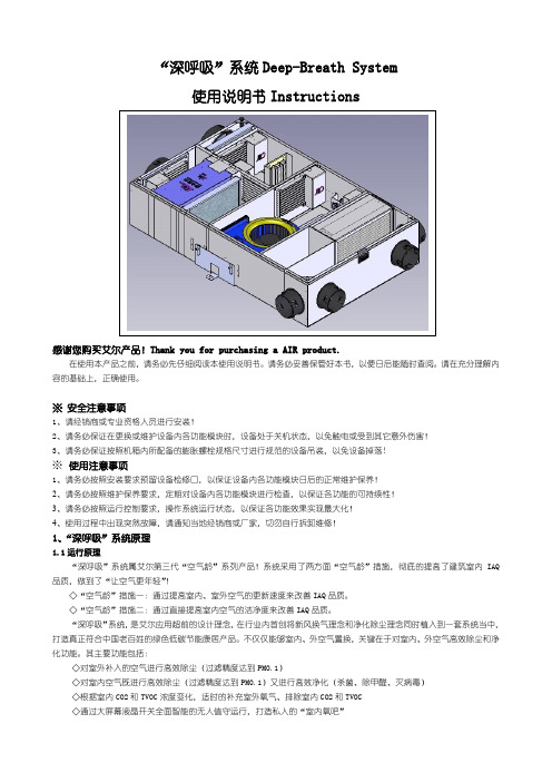
※安全注意事项1、请经销商或专业资格人员进行安装!2、请务必保证在更换或维护设备内各功能模块时,设备处于关机状态,以免触电或受到其它意外伤害!3、请务必保证按照机箱内所配备的膨胀螺栓规格尺寸进行规范的设备吊装,以免设备掉落!※使用注意事项1、请务必按照安装要求预留设备检修口,以保证设备内各功能模块日后的正常维护保养!2、请务必按照维护保养要求,定期对设备内各功能模块进行检查,以保证各功能的可持续性!3、请务必按照运行控制要求,操作系统运行状态,以保证各功能效果实现最大化!4、使用过程中出现突然故障,请通知当地经销商或厂家,切勿自行拆卸维修!1、“深呼吸”系统原理1.1运行原理“深呼吸”系统属艾尔第三代“空气龄”系列产品!系统采用了两方面“空气龄”措施,彻底的提高了建筑室内IAQ 品质,做到了“让空气更年轻”!◇“空气龄”措施一:通过提高室内、室外空气的更新速度来改善IAQ品质。
◇“空气龄”措施二:通过直接提高室内空气的洁净度来改善IAQ品质。
“深呼吸”系统,是艾尔应用超前的设计理念,在行业内首创将新风换气理念和净化除尘理念同时植入到一套系统当中,打造真正符合中国老百姓的绿色低碳节能康居产品。
不仅仅能够室内、外空气置换,关键在于对室内、外空气高效除尘和净化功能。
其主要功能包括:◇对室外补入的空气进行高效除尘(过滤精度达到PM0.1)◇对室内空气既进行高效除尘(过滤精度达到PM0.1)又进行高效净化(杀菌、除甲醛、灭病毒)◇根据室内CO2和TVOC浓度变化,适时的补充室外氧气、排除室内CO2和TVOC◇通过大屏幕液晶开关全面智能的无人值守运行,打造私人的“室内氧吧”1.2结构原理2、“深呼吸”系统安装2.1主机安装◇请将主机安装在足以承受机器重量的地方。
DB 操作流程新版

Row pitch 行间距
4.55
Pad size x Pad x 尺寸 2
Pad size y Pad y 尺寸 3
备注
需求文件PCB 图纸,PCB不同, 参数设置会有所不同
CORPORATE CONFIDENTIAL 内部资料
9
三 ASIC Bonding程序编辑
2、work holder调试,align LF position设定; 校准方法如下: 使用摇杆将镜头中心对准第一个产品中心位置
释义
设置参数
点胶器XY在点胶器Z开始上移之后 10 的延迟时间
点胶器Z在点胶之前和点胶器XY在 10 开始移到点胶位置之后的时间
根据委托单确认PCB型号,胶水型号,芯片物料是否正确 根据PCB行列要求准备压块,根据胶水型号及工艺准备点胶针头 可根据芯片尺寸选择吸嘴
4
二 设备配件更换及校准
1、压块更换 根据PCB间距选择相对应的压块, 装压块要素:
① 拧紧两个大螺丝到适当位置, 保证四根压筋紧贴轨道 ②4个小顶丝 对角顶丝相互拧紧调 试,保证四根压筋紧贴轨道,一直 调试到压块固定为止
备注
一般情况下 与焊接个数 设置相同
需求文件PCB 图纸
CORPORATE CONFIDENTIAL 内部资料
8
三 ASIC Bonding程序编辑
lead frame 参数编辑;
修改项目
释义
设置参数
Number of PCB 列数 26 columns
Column
列间距
2.93
pitch
Number of PCB 行数 12 Rows
CORPORATE CONFIDENTIAL 内部资料
DB Technologies Ingenia IG1T 快速启动用户手册说明书

IG1TQuick start user manualSection 1The warnings in this manual must be observed together with the "User Manual - Section 2".Le avvertenze nel presente manuale devono essere osservate congiuntamente al “MANUALE D’USO - Sezione2”.Die Warnungen in diesem Handbuch müssen in Verbindung mit der "BEDIENUNGSANLEITUNG - Abschnitt 2" beobachtet werden”.Les avertissements specifiés dans ce manuel doivent être respectés ainsi que les "CARACTERISTIQUES TECHNIQUES -Section 2"A.E.B. Industriale Srl Via Brodolini, 8 Località Crespellano 40053 VALSAMOGGIA BOLOGNA (ITALIA)Thank you for choosing a dBTechnologies Product!INGENIA IG1T is a powerful 2-way vertical speaker, equipped with one 1” compression driver with a 1.4” voice coil and two 6.5” woofers, in an innovative shape. The horn of the driver is vertically asymmetrical, for a precise acoustical coverage in different kind of installations, indoor and outdoor. The powerful DIGIPRO ® G3 amplifier section, capable of handling up to 400 W (RMS power), is controlled by a DSP, which can perform a detailed customization of the output sound of the speaker. In particular, the DSP can recognize if 2 INGENIA IG1Ts are installed together, stacked or flown, through the special IR communication handles, and can perform a digital steering, making them sound as one single source with a selectable inclination. All the DSP parameters can be viewed and selected in the user-friendly interface, equipped with a self-rotating OLED display, and can be saved and reloaded in different custom settings by the user, who can protect his choices with a password.Check the site for the complete user manual!1) Unpacking: The box contains:N°1 INGENIA IG1TN°1 Mains cable with Neutrik® powerCON TRUEconnectorN°1 100-120 V FUSEThis quick start and warranty documentation.2) Easy Assembly:The speaker can be configured in 4 main modes:Option 1: Single Mode (1 or 2 speakers mounted on an optional pole stand)The speaker is equipped with a standard pole-mounting hole, so it can be mounted on a D35 mm optional pole stand (tripod). The user must check the stability of the system. The maximum admitted height is 150 cm (47.25 inch.) for one speaker, 120 cm (59.1 inch) for two speakers.Option 2: Stacked on a subwoofer (1 or 2 speakers) The speaker can be mounted on a subwoofer using a DS2-S optional mini pole. When using a 2-speakers configuration, it is mandatory to use a couple of LP-IG optional link brackets to mount them together.Option 3: Pole-mounted on a subwoofer (1 speaker) Only one speaker can be installed on a D35 pole (maximum height: 150 cm – 59.1 in.), mounted on asubwoofer. It is mandatory to use an additional fastening system to secure properly the installation. Option 4: Flown (1 or 2 speakers)The speaker can be mounted flown, using an optional DRK-IG fly bar and TA-IG truss adapter. In a 2-speakers configuration, it is mandatory to use a couple of LP-IG optional link brackets to mount them together . / Other kinds of installation not illustrated in this manual are not admitted. /Don’t cover the handles inany way, they are equipped with infrared ports!3) Connections and OLED DisplayThe INGENIA speakers are equipped with an intuitive OLED display. All the connections are in the amplifierpanel side:1 – Peak led.2 – OLED Display.3 – Push rotary encoder (rotate: select, push: confirm).4 – Mini B-type USB port (for firmware updating).5 – Link audio output.6 – Combo line/mic input.7 – Input sense switch (LINE/MIC).Single Mode (1 or 2 IG1T ) Stacked on a subwoofer (1 or 2 IG1T)Flown(1 or 2 IG1T)Pole-mounted on a subwoofer(1 IG1T)8 – Auto-range mains (power) input. 9 – Mains (power) link output. 10 – Mains fuse.The fuse is factory setted for 220-240 V operation.If it is necessary to change the fuse to 100-120V range:1. Disconnect the speaker from any cable2. Wait 5 minutes3. Substitute the fuse with the correct one suppliedUse only cables with Neutrik® connectors!4) Ready in less than a minute – Build System menu The internal DSP provides an easy setup of installation and allows to configure quickly the IG1T. Even if you turn off the speaker, your setting will be saved for the next session!Set up instructionsOnce you have properly connected the power supply and audio input (remember to select the proper “LINE”/”MIC” choice in input sense switch (7)), select the gain level in the first display window, rotating the push rotary encoder, then push it to access the menu choice wizard.1. Select and confirm“Build System”,2. Select and confirm the"Selfcheck System” to launch the automatic recognition procedure and select and confirm “NEXT”3. In the next “SystemStructure” menu you can find the number of“Speakers” automatically recognized, and you can choose and confirm the number of “Subwoofers” you want to use in your configuration. Then select and confirm “NEXT” 4. In “System Type” you can specify the “Stacked”(pole mounting – subwoofer mounting) or “Flown” (fly-bar mounting) type of installation. Then select and confirm “NEXT”Holding the rotary encoder, you return to the main Gain/Level window, from each submenu window.If the system has automatically recognized the presence of 2 speakers, the next menu will be “System coverage”. If you have selected the presence of a subwoofer in your installation, the next menu will be the “Subwoofer Matching” menu.5) System CoverageThe INGENIA IG1T’s powerful DSP can act as a custom delay line on the transducers, inorder to direct the final acoustical coverage of the speaker. This menu will appear only when the DSP has recognized 2 IG1Ts thanks to the infrared handles. You can choose up to 7 factory settings:a. UP +10°, for the maximum inclination angle(with speakers mounted on a stand or a subwoofer)b. UP +5°, for a medium inclination angle (withspeakers mounted on a stand or a subwoofer) c. UP +2.5°, for a low inclination angle (withspeakers mounted on a stand or a subwoofer) d. FAR 0°, for the maximum distance coverage ina position directly at the level of the audience e. DOWN -2.5°, for a long-distance coverage(flown speakers)f. DOWN -5°, for a medium-distance coverage(flown speakers)g. DOWN -10°, for a short-distancecoverage(flown speakers)6) Subwoofer MatchingOnceyouhave chosen to match the system to one or more subwoofers, a menu will appear allowing you to select: the model and the HPFilter frequency, and the system will suggest you the correct subwoofer delay.7) System DelayYou can set a custom delay on your speakers inmilliseconds, meters or feet, in order to align yourspeakers with the main sound system (see the picture below).8) Stage AlignmentWhen you are on stage and you have different acoustic sources (for example thedrums of a band) you can choose to align yourspeaker with those sources. In this menu you can set the distance in meters or feet, or the time in ms.SUPERUSER PASSWORDYou can set a Password in OPTIONS PASSWORD in order to protect your custom settings.If you forget the password, use the code: Q2R5D9 to unlock the system.Technical DataSpeaker Type : 2-way Active SpeakerAcoustical dataFrequency Response [-10dB]: 85 - 20.000 Hz Frequency Response [-6dB]: 92 – 19.200 Hz Max SPL : 128 dBHF compression driver : 1" Exit HF voice coil : 1.4” TitaniumHorn Coverage (HxV): 100 x 80° (+15°/-65°) Directivity : Vertical asymmetricHF type : Neodymium compression driver Crossover frequency : 2100 Hz LF : 2x6.5”LF Voice Coil : 1.5”LF Type : NeodymiumAmplifierAmp Technology : Digipro® G3 Amp Class : Class-D RMS Power : 400 WPeak Power: 800 WProcessorController : DSP 56 bitAD/DA Converter : 24 bit / 48 kHzLimiter : Dual Active, Peak, RMS, ThermalInputSignal Input : 1x Combo IN (XLR/Jack) Signal Out : 1 XLR link OUT USB connector : Yes – mini USBMechanicsHousing: Polypropylene PP reinforced by internal metal structureGrille : FULL / Invisible screws Flyable: YesHandles : 1x on TOP / 1x on BOTTOM Pole Mount : Yes, 36 mm Width : 195 mm (7.68 in) Height : 536 mm (21.10 in) Depth : 271 mm (10.67 in) Weight : 10.8 kg – (23.81 lbs.)User Interface : OLED display + push rotary encoder Self-rotating display : yesPositioning : EPD (Element Position Detection) Display mirroring : YesDownload the complete user manual on: www.dbtechnologies/Downloads.aspxEMI CLASSIFICATIONAccording to the standards EN 55103 this equipment is designed and suitable to operate in E3 (or lower E2, E1) Electromagnetic environments. FCC CLASS B STATEMENT ACCORDING TO TITLE 47, PART 15, SUBPART B, §15.105This equipment has been tested and found to comply with the limits for a Class B digital device, pursuant to part 15 of the FCC Rules. These limits are designed to provide reasonable protection against harmful interference in a residential installation.This equipment generates, uses and can radiate radio frequency energy and, if not installed and used in accordance with the instructions, may cause harmful interference to radio communications.However, there is no guarantee that interference will not occur in a particular installation. If this equipment does cause harmful interference to radio or television reception, which can be determined by turning the equipment off and on, the user is encouraged to try to correct the interference by one or more of the following measures: 1. Reorient or relocate the receiving antenna.2. Increase the separation between the equipment and receiver.3. Connect the equipment into an outlet on a circuit different from that to which the receiver is connected.4. Consult the dealer or an experienced radio/TV technician for help.WARNING: Make sure that the loudspeaker is securely installed in a stable position to avoid any injuries or damages to persons or properties. For safety reasons do not place one loudspeaker on top of another without proper fastening systems. Before hanging the loudspeaker check all the components for damages, deformations, missing or damaged parts that may compromise safety during installation. If you use the loudspeakers outdoor avoid spots exposed to bad weather conditions.Contact dB Technologies for accessories to be used with speakers. dBTechnologies will not accept any responsibility for damages caused by inappropriate accessories or additional devices.Features, specification and appearance of products are subject to change without notice.dBTechnologies reserves the right to make changes or improvements in design or manufacturing without assuming any obligation to change or improve products previously manufactured.Scan with your QR Reader App to download the complete User Manual。
PS6000+自动化系统用户操作手册(汇编)

国电南自PS 6000+自动化系统用户操作手册国电南京自动化股份有限公司GUODIAN NANJING AUTOMATION CO.,LTD.PS 6000+自动化系统用户操作手册国电南京自动化有限公司2009年12月1日* 本说明书可能会被修改,请注意最新版本资料* 200 年月第版第次印刷版本声明本说明书适用于PS 6000+自动化系统V1.2版本1.软件软件版本V1.22.硬件产品说明书版本修改记录表* 技术支持电话:(025)83537220传真:(025)83537201* 本说明书可能会被修改,请注意核对实际产品与说明书的版本是否相符* 2009年10月第3版第1次印刷* 国电南自技术部监制目录版本声明1 启动控制台 (1)1.1启动方法 (1)1.2启动进程 (1)1.3用户管理 (2)1.4退出进程 (5)2 实时进程 (6)2.1实时库服务进程 (6)2.2103规约进程 (6)2.3在线系统 (6)2.4告警显示窗 (25)2.5用户管理 (30)2.6计算服务 (30)2.7历史服务 (30)2.8保护设备管理 (30)2.9曲线 (38)2.10实时库浏览 (41)3 高级应用 (42)3.1拓扑分析 (42)3.2事故追忆 (42)4 报表浏览器 (44)4.1报表浏览器菜单项 (44)4.2报表打印 (46)5 故障录波分析软件 (49)5.1使用界面整体介绍 (49)5.2菜单 (50)1 启动控制台PS 6000+自动化系统的进程都集中在控制台,用户可以通过控制台启动或停止各进程。
1.1 启动方法方法一:单击电脑桌面上的控制台图标方法二:打开终端,输入命令:$cd $CPS_ENV/bin$./console控制台启动后界面如图1所示:图 11.2 启动进程控制台把进程分为三类,分别是配置工具、功能配置和实时进程。
每类对应一个按钮,点击按钮,弹出下拉框,列出该分类下的常用进程,选中即可启动对应进程。
DBMANUAL精讲

禁用相机图 设置图像显示器 设置图像显示器 设置图像显示器显 像显示器 显示Wafer图像 显示Preform图像 示Bonding图像
显示F/W/P/B manual move常用 的一些操作选项
显示现在所设定的类 别
显示Frame 手 设置为自动〔连续〕作业流程模式 动传送的界面
启用/禁用导线架 传送功能,该项 选中即可自动传 送导线架到轨道
显示Wafer 手 动移动的界面
显示Preform 手 动移动的界面
启用/禁用Wafer 传送功能
显示Bonding手 动移动的界面
显示主菜单栏
开启/关闭晶 圆地图功能
设定上片 预定数
显示实际上 设定估量要作
片的数量
业的导线架数
显示作业的导 线架总数量
手动移动 Wafer table
移动Wafer table到 接收/弹出Wafer处
按pitch步进 移动wafer
传送出Wafer到Cassette
取一枚Wafer到 Wafer holder
Wafer扩张环 上升/下降
胡椒罐上 升/下降
Cassette 按 层上升/下降
手动移动Wafer table上升/下降
Y方向手动移 动导线架吸 取装置
Stage手动移 动上升/下降
复归Load导线架 和料盒的动作
Z方向手动 移动导线架 吸取装置
复归Unload料盒的动作
执行导线架吸 取的周期操作
执行导线架吸取 的单步操作
移动Frame Stacker到添加 导线架处的高度,Loader arm停在丢纸的位置
Prefrom处夹 子翻开/闭合
在Y方向移动导线架吸 取装置到轨道位置
ABB 软启动器 PS D 和 PS DH 产品说明书

Softstarter range type PSD & PSDH2ABB Automation Technology Products AB/ Control, Id No: 1SFC132002C0201, March 2003Softstarters type PS D and PS DHABB’s solid state starter range is used when it is important to have a smooth start-up of various types of motor drives.Instead of switching directly to full voltage the softstarter ensures a gradual voltage increase.ABB’ s Softstarter is available in four versions, PS 75…840and PS DH 30…720.PS D 75…PS D 840 and PS DH 30…PS DH 720 softstart-ers have a robust design in metal housing for many types of applications, both normal duty and heavy duty. Flexible parameter settings with potentiometers and clear indication with LEDs of status and faults on front of the unit. Theoptional built in advanced electronic overload relay (always included as standard for PS DH versions) provides much better motor protection than a conventional bimetallic relay,for example in intermittent duty.DescriptionThe operator panels for PS DH have LED´s, potentiometers and switches for indication and settings.1S F T 98899-032Quck guide for selectionBy using the guide below you can quickly select a suitable ABB Softstarter for the most common applictions. If a more precise selection is required you can use Prosoft, a selection software available at /lowvoltage.3ABB Automation Technology Products AB/ Control, Id No: 1SFC132002C0201, March 2003Motor power Rated220-230 V 380-400/415 V 500 V 690 Vmotor current Order codeP e P e P e P e I e Type Supply voltage U s Supply voltage U s kWkWkWkWAPS D110-127 V,50/60 Hz220-240 V,50/60 Hzkg2237––28–757510––45–28-7575103055––70–1101101SFA 88 4205-F 1SFA 88 4205-L 11––75–70–110110113775––87.5–14514513––90–87.5–145145134590––105–17517525––110–105–1751752555110––140–21021028––132–140–2102102875132––140–25025028––160–140–2502502890160––175–30030028––200–175–30030028110200––210–37037051––250–210–37037051–––355100–3703701SFA 88 6211- A51132250––280–47047051––315–280–47047051–––450250–4704701SFA 88 6212- A 51160315––350–57057054––400–350–57057054–––560300–5705701SFA 88 6213-1SFA 88 6213-A 54200400––420–72072054––500–420–72072054–––710375–7207201SFA 88 6214-1SFA 88 6214-A 64250450––525–84084064––560–525–84084064–––800500–8408401SFA 88 6215-1SFA 88 6215-A 64Ordering data Softstarter PS D 75 (840)PS D 75…840 For normal startsWeight4ABB Automation Technology Products AB/ Control, Id No: 1SFC132002C0201, March 2003Ordering data Softstarter PS DH 30 (720)Motor power Rated 220-230 V 380-400/415 V 500 V motor current Order codeP e P e P e I e Type Supply voltage U s Supply voltage U s WeightkWkWkWAPS DH110-127 V,50/60 Hz220-240 V,50/60 Hzkg7.515–14–30301SFA 88 4301-B 1SFA 88 4301-10––18.514–30301SFA 88 5301-B 1SFA 88 5301-101522–28–45451SFA 88 4302-B 1SFA 88 4302-10––3028–45451SFA 88 5302-B 1SFA 88 5302-1018.530–35–60601SFA 88 4303-B 1SFA 88 4303-10––3735–60601SFA 88 5303-B 1SFA 88 5303-102237–42–75751SFA 88 4304-B 1SFA 88 4304-11––4542–75751SFA 88 5304-B 1SFA 88 5304-113055–70–1101101SFA 88 4305-B 1SFA 88 4305-13––7570–1101101SFA 88 5305-B 1SFA 88 5305-133775–87.5–1451451SFA 88 4306-B 1SFA 88 4306-25––9087.5–1451451SFA 88 5306-B 1SFA 88 5306-254590–105–1751751SFA 88 4307-B 1SFA 88 4307-28––110105–1751751SFA 88 5307-B 1SFA 88 5307-2855110–140–2102101SFA 88 4308-B 1SFA 88 4308-28––132140–2102101SFA 88 5308-B 1SFA 88 5308-2875132–140–2502501SFA 88 4309-B 1SFA 88 4309-28––160140–2502501SFA 88 5309-B 1SFA 88 5309-2890160–175–3003001SFA 88 4310-B 1SFA 88 4310-52––200175–3003001SFA 88 5310-B 1SFA 88 5310-52110200–210–3703701SFA 88 4311-B 1SFA 88 4311-52––250210–3703701SFA 88 5311-B 1SFA 88 5311-52132250–280–4704701SFA 88 4312-B 1SFA 88 4312-55––315280–4704701SFA 88 5312-B 1SFA 88 5312-55160315–350–5705701SFA 88 4313-B 1SFA 88 4313-55––400350–5705701SFA 88 5313-B 1SFA 88 5313-55200400–420–7207201SFA 88 4314-B 1SFA 88 4314-65––500420–7207201SFA 88 5314-B1SFA 88 5314-65PS DH 30...720 For heavy duty starts* For 690V red code letters are used.5ABB Automation Technology Products AB/ Control, Id No: 1SFC132002C0201, March 2003General technical dataGeneral technical data PS D 75...840 and PS DH 30 (720)PS D 75 (145)PS D 175 (840)PS DH 30 (110)PS DH 145 (720)Rated insulation voltage U i V 690690690690Rated operational voltage U e V 220–500220–690220–500220-500Starting capacity at max rated current I e4,5 x I e for 14s5 x I e for 7s 5 x I e for 25s 5 x I e for 25s Number of starts per hour6 4) 3 4) 6 4) 1 4)Overload capacity Overload class A 10103030Service factor %100100100100Ambient temperature During operation 1)°C 0 – 500 – 500 – 500 – 50During storage°C -40 – +70-40 – +70-40 – +70-40 – +70Degree of protectionIP 00IP 00IP 00IP 00SettingsRamp time during start sec 0.5 – 600.5 – 600.5 – 600.5 – 60Initial voltage during start %10 – 6010 – 6010 – 6010 – 60Ramp time during stopsec 0.5 – 2400.5 – 2400.5 – 2400.5 – 240Step down voltage special ramp %100 – 30100 – 30100 – 30100 – 30Current limit function2 – 5 x I e 2 – 5 x I e 2 – 5 x I e 2 – 5 x I e Adjustable rated motor current I e 2)%70 – 10070 – 10070 – 10070 – 100Switches forEnergy saving function ON/OFF (PF)Yes Yes Yes Yes Kick start, YES/NO(KICK)Yes Yes Yes Yes High current switch off, YES/NO (SC)Yes Yes Yes Yes Reaction time for energy saving normal/slow(TPF)Yes Yes Yes Yes Signal relays Fault signalK6Yes Yes Yes Yes By-pass signal, start ramp completed K5Yes Yes Yes Yes Run signalK4Yes Yes Yes Yes Overload signalYes Yes Yes Yes Rated operational voltage U e V 250250250250Rated thermal current I thA 5555Rated operational current I e at AC-15 (U e =250V)A1.51.51.51.5Signal indication (LED)Fault (F1 and/or F2) red Yes Yes Yes Yes Overload (OVL) yellow 3)Yes 3)Yes 3)Yes Yes Ready to start/stand by (ON) green Yes Yes Yes Yes Running (R) yellow Yes Yes Yes Yes Completed start ramp (T) yellow Yes Yes Yes Yes Energy saving function active (P) yellow Yes Yes Yes Yes1) Above 40 °C, up to max 50 °C, reduce the rated current with 0.8 % per °C. 2) For U e = 690 V; setting 50 – 100 %. 3) Optional for PSD types.4) When more than stated starts per hour are required, contact your sales office.Cross section of connection cables PS D and PS DHType PS D 75110...145175...570720840Type PS DH 30 (60)75 (110)145 (470)570720Main circuitConnection clampCu-cable mm 235––––Al-cable mm 235––––Connection barWidth x thickness mm –15x425x640x650x6Hole diameter mm –7111111Tightening torque min.Nm 2.5 2.4(M6)12.0(M10)12.0(M10)12.0(M10)(For guidance only)max.Nm 3.0 3.2(M6)16.0(M10)16.0(M10)16.0(M10)Supply and control circuit Connection clampmm 22.52.52.52.52.56ABB Automation Technology Products AB/ Control, Id No: 1SFC132002C0201, March 2003Recommended ABB Power re-Overload protection Maxquirements Current rangepower loss of supply at max /e Max fuse rating main circuit 4)circuit SizeTypeAWBussman fusesFerraz fusesVAPS S03TA 25 DU 2.2–3.1–16 A 170M1359212TA 25 DU 10–14–40 A 170M1363225TA 25 DU 18–25–50 A 170M13645PS S18/30TA 25 DU 6–183)50 A 170M13645)63 A 6.6 URB 000 D08 V 0063930/52TA 25 DU 10–303)80 A 170M13665)100 A 6.6 URB 000 D08 V 0100937/64TA 42 DU 22–373)125 A 170M13685)160 A 6.6 URB 000 D08 V 0160944/76TA 75 DU 29–443)160 A 170M13695)200 A 6.6 URD 30 D08 A 0200950/85TA 75 DU 29–503)160 A 170M13695)200 A 6.6 URD 30 D08 A 02001060/105TA 75 DU 29–603)200 A 170M13705)250 A 6.6 URD 30 D08 A 02501072/124TA 75 DU 45–723)250 A 170M13715)315 A 6.6 URD 30 D08 A 03151085/147TA 110 DU 65–853)315 A 170M13725)400 A 6.6 URD 30 D08 A 040036105/181TA 110 DU 65–1053)400 A 170M30196)400 A 6.6 URD 30 D08 A 040036142/245TA 200 DU 100–1423)450 A 170M30206)500 A 6.6 URD 30 D08 A 050036175/300TA 200 DU 100-1753)500 A 170M30216)530 A 6.6 URD 30 D08 A 055065250/430TA 450 DU 130-2503)700 A 170M40176)630 A 6.6 URD 31 D08 A 063065300/515TA 450 DU 130-3003)900 A 170M50156)900 A 6.6 URD 32 D11 A 090065PS D75TA 75 DU 7)45–753)250 A 170M13715)315 A 6.6 URD 30 D08 A 031540110TA 110 DU 7)65–1103)315 A 170M13725)400 A 6.6 URD 30 D08 A 040040145TA 200 DU 7)100–1453)400 A 170M30196)400 A 6.6 URD 30 D08 A 050040175TA 200 DU 7)100–1752)450 A 170M30206)500 A 6.6 URD 30 D08 A 050065210TA 450 DU 7)130–2102)500 A 170M30216)530 A 6.6 URD 30 D08 A 055065250TA 450 DU 7)130–2502)630 A 170M40166)550 A 6.6 URD 31 D08 A 055065300TA 450 DU 7)130–3002)700 A 170M40176)630 A 6.6 URD 31 D08 A 063065370TA 900 DU 7)265–3702)900 A 170M50156)900 A 6.6 URD 32 D11 A 090090470TA 900 DU 7)265–4702)900 A 170M50156)1250 A 6.6 URD 33 D11 A 125090570TA 900 DU 7)265–5702)1500 A 170M60186)1250 A 6.6 URD 33 D11 A 125090720TA 900 DU 7)465–7202)1800 A 170M60206)2000 A 6.6 URD 233 PLAF 200090840TA 900 DU 7)465–8402)1800 A170M60206)2000 A6.6 URD 233 PLAF 200090PS D(690V)370TA 450 DU 130–3702)900 A 170M50156)900 A 6.6 URD 32 D11 A 090090470TA 900 DU 265–4702)1250 A 170M50186)1250 A 6.6 URD 33 D11 A 125090570TA 900 DU 265–5702)1500 A 170M60186)1250 A 6.6 URD 33 D11 A 125090720TA 900 DU 465–7202)1500 A 170M60186)2000 A 6.6 URD 233 PLAF 200090840TA 900 DU465–8402)1500 A 170M60186)2000 A 6.6 URD 233 PLAF 200090PS DH301)3)125 A 170M13685)160 A 6.6 URD 30 D08 A 016040451)3)200 A 170M13705)200 A 6.6 URD 30 D08 A 020040601)3)250 A 170M13715)250 A 6.6 URD 30 D08 A 025040751)3)315 A 170M13725)315 A 6.6 URD 30 D08 A 0315401101)3)400 A 170M30196)450 A 6.6 URD 30 D08 A 0450401451)2)450 A 170M30206)500 A 6.6 URD 30 D08 A 0500651751)2)500 A 170M30216)550 A 6.6 URD 30 D08 A 0550652101)2)630 A 170M40166)630 A 6.6 URD 31 D08 A 0630902501)2)700 A 170M40176)700 A 6.6 URD 32 D08 A 0700903001)2)900 A 170M50156)900 A 6.6 URD 32 D08 A 0900903701)2)900 A 170M50156)1000 A 6.6 URD 33 D08 A 1000904701)2)1250 A 170M50186)1250 A 6.6 URD 33 D08 A 1250905701)2)1500 A 170M60186)1600 A 6.6 URD 33 TTF A 1600907201)2)1800 A 170M60206)2000 A 6.6 URD 233 PLAF 200090Technical data1) Electronic overload relay built in, class 305) Fuse holder 170H 10072) Total power loss: P Ltot = [3 x I e x 1.0] + 100 (W) Reduced to 100 W only when using by-pass 6) Fuse holder 170H 30043) Total power loss: P Ltot = [3 x I e x 1.0] + 50 (W) Reduced to 50 W only when using by-pass 7) Not required if using the optional electronic o.l.4) For the supply circuit: 6 A delayedSize related data7ABB Automation Technology Products AB/ Control, Id No: 1SFC132002C0201, March 2003DimensionsPS D 75PS DH 30 (60)PS D 370...840PS DH 300 (720)PS D 110...145PS DH 75 (110)PS D 175...300PS DH 145 (250)1S F T 98899-0141S F T 98899-0191S F T 98899-0181S F T 98899-0151S F T 98899-020 e d .21S F T 98899-021All dimensions in the table +/- 5 mmDimensionTypeE F K L M N PS D370…570PS DH300…47033.52562.5125173.526PS D720PS DH570414060110173.55PS D840PS DH720465060100173.551S F T 98899-027Dimensions Type No.E F G H PS D75PS DH30...60280360313218PS D110...145PS DH75...110280*********PS D175...300PS DH145...250382444402310PS D370...840PS DH300 (720)540600600310Minimum distance to wall/front A = 20 mm B = 10 mm C = 100 mm Both top and bottom D = 150 mm Both top and bottomMinimum distance to wall/front8ABB Automation Technology Products AB/ Control, Id No: 1SFC132002C0201, March 2003Circuit diagramsE1Circuit board E3–E5FanF6Temperature monitor J1–J3Contact blocks K4Relay, actuated in operational position K5Relay, actuated at full voltage (U e = 100 %)K6Relay, fault signal T2Current transformer T5Control transformerV1–V6Thyristor X1–X3Terminal blockPS D without electronic overload relayE1Circuit board E2Circuit board OVL E3–E5Fan F6Temperature monitor J1–J3Contact blocks K3Relay, overload K4Relay, actuated in operational position K5Relay, actuated at full voltage (U e = 100 %)K6Relay, fault signal T2Current transformer T3Current transformer T5Control transformerV1–V6Thyristor X1–X3Terminal blockPS D and PS DH with electronic overload relay1S F T 98899-0241S F T 98899-025。
SAP_PS-PS模块配置和操作手册-V1.1-trigger_lau

SAP PS模块配置和操作手册SA P PS模块配置和操作手册Overview项目管理项目管理总的来说就是需要管理整个项目实施的过程,在这个过程中,需要将各级任务进行分解,也就是通常说的WBS。
对于分解的任务需要相当于一个单独的计划,需要有对应的开始结束时间、资源,具体每个任务还会涉及到具体的处理过程,例如:内部加工、采购材料、提交某个文档等,需要依据不同的任务类型进行不同的管理。
项目下可以设置WBS,以分解各项工作进行管理。
在SAP中,为了核算的需求,在每个wbs下设置了network,用于成本的归集network也是一种订单,同内部订单一样,类型不同而已。
在每个network分不同的作业,如果是一个内部作业,下面可以挂一个物料组件,直接关联到MM 模块,进行采购操作。
PS 模块说明SAP的PS模块一方面的功能是可以按照项目管理的要求进行项目、WBS的管理,同时为了进行日常事务的细分管理,使用了网络(Network)的概念,在网络下可以定义不同的作业,每个做再对应到是一个物料采购任务还是说一个工序加工任务。
SAP的PS模块提供生成甘特图,并通过图形化方式管理Network。
项目定义(Project Definition)和WBS都是一个成本对象,可以进行成本的归集,月底进行成本的结转,具体如何结转通过结算规则来控制.预算、结算的设置是通过参数文件的方式来定义,然后分配给项目定义和WBS,这一点是同内部订单类似的。
SAP的PS模块中还可以对资源的能力进行查看,操作者就可以依据资源的情况进行调整TableConfigureCreate User Status —OK02IMG菜单路径:项目系统一>结构->实施结构-〉工作分解结构一> WBS用户状态一〉创建参数文件可以配置一下看看,和内部订单的比较类似,暂时没有使用这个状态。
执行继续后双击状态参数.分配状态参数使用的类型.Create Project Profile-计划版和日期、控制需要重新配IMG 菜单路径:项目系统->结构一〉实施结构-〉工作分解结构一〉创建项目参数文件事务代码:OPSACreate Project type for WBS elementsIMG菜单路径:项目系统一>结构一>实施结构一〉工作分解结构(WBS)—>创建WBS 元素项目类型此处的定义是为了维护WBS主数据中的项目类型字段的值。
DBSPI配置手册说明书

DBSPI Configuration Manual:1.Add the virtual node in the node bank. Also configure the advance option in add node wizard.Please check Induction manual “Addition of the Node”.NOTE: In the advance option check the Cluster Virtual Node and fill the HA ResourcesGroup. Add the nodes where DB is running.2.Put the virtual node into the Oracle (UNIX) node group.3.To configure the DBSPI we required some information as shown below…Database NameResource group nameVirtual NameOracle HomeCluster serversServer where Database is ONLINEListener Name and PathRMAN PathAlert Log File PathTable Space Monitoring or HPOVO log file Path.See below…this information will be provided by the Oracle Database team.New HP Open View policies are to be deployed for monitoring the BSISPRD database.The Oracle home is:BSISPRD - /opt/local/bsispdbs/oracle/10gPlease configure the policies accordingly.1. RMAN log policyRMAN log file location:/opt/local/bsispdbs/oracle/10g/scripts/rman/logs/hotbackups/opt/local/bsispdbs/oracle/10g/scripts/rman/logs/coldbackups/opt/local/bsispdbs/oracle/10g/scripts/rman/logs/archive_logs2 .Tablespace monitoring policyHp open view log files:/opt/local/bsispdbs/oracle/10g/scripts/check/logs/hpopen.log3. Alert Log and Listener Log Monitoring PolicyAlert Log Path:/opt/local/bsis pdbs/admin/bdump/alert_bsisprd.logListener Log Path:/opt/local/bsispdbs/oracle/10g/network/log/bsisprd_listener.logDatabase is clustered in (TCPPDBS061, TCPPDBS007, TCPPDBS005, and TCPPDBS044).The HP_DBSPI user is also created according to the SEC1.Also find the information in the format below:4.Always remember that to configure you required a DBSPI user.er name: hp_dbspiii.Password: hp_dbspiIf the database is in cluster:•Based on the resource group name and information provided, apminfo.xml file has to be created with the mapping and copied to the following directory on each node in the cluster:/var/opt/OV/conf/conf•Always maintain a local copy in the management server Path: /opt/local/software.•Also check the following parameter locally on the server (DB node)o/opt/OV/bin/ovconfget | grep MONITORIf the parameter has not set or set to FALSE then set the parameter by running the following command. (This will enable cluster monitoring by setting MONITOR_MODE=TRUE key in conf.cluster namespace of that particular server.)On the manage node issue the command,sudo /opt/OV/bin/ovconfchg -change –ns conf.cluster -set MONITOR_MODE TRUE sudo /opt/OV/bin/ovc -restartOr you can usesudo /opt/OV/bin/ovc –killsudo /opt/OV/bin/ovc –start5.Assign Discovery and Message Templates to virtual node and deploy it by selecting templates,action, commands, and monitor.6.Now you required to run the DB Discovery program by selecting node. This is required becausethe discovery program creates some specific folder or files in on manage node which required by the DBSPI to configure DBSPI – Templates to setup the monitoring.DBSPI Discovery program is present in OVO bank go to windows tab --- Application Bank --- here a windows will open which has lists of all the application. Here you will find an icon named DBSPI. Double click on the icon. A new window will open. This window will have the DBSPI Admin and DBSPI. This will make entry in the different files or folder.7.To configure the DBSPI on the UNIX management server, you required to go into the DBSPIapplication…Here select the node and run the “Configure DB Connections”. Here an editor will appear where you need to provide the information in the EOF (End of the File) as given below…8.Then save the information…first time you may see a failed word which means the Database isnot running on that server or may be some error in the hp_dbspi user. If this is not a problem with the user then run the following command from the management server…sudo ovdeploy –cmd “dbspicol OFF <instance_name>” –host <node-name>9.Then again try to save the configuration. This time you see that everything is fine.See the below following screen shots…Enter the configurationinformation.Example of the FAILED…10.Also put the physical node in Node Group bank in group Oracle-Custom.11.Set the File System monitoring for given Database.Go to the Template window…Toyota > Toy OS Sun > File System.Click on the condition option or button. A window will appear.Find Name “Space on FileSystem [OSSPI-FileSystemMsg-4.2] for the Databases(x).Where x is the number 1, 2, 3…Put the name of the instance in the “Message Text” area.Select the template then click on the “condition” button. You can find it on the right hand side at the bottom of appear window or Template Window.Find the condition for the Database File System (DB FS) monitoring. As seen below…The condition name should be like as underline below in the screen shot. Then click modify you can able to see a new window with some information…as shown next…Enter the database instance name in the under line area and click OK.NOTE: Do not enter more than 15 instance name as the template work will be affected. If the instance reached to 15 then create a new template my copying the existing template change the name according to the naming convention. Then remove the entry from the under line area. (Only the instance name). Then do same as previously.12.Set the Listener monitoring Policy for given Database.Go to the Template window…Toyota > Toy Oracle RMAN > Toy Listener for Database(x)This is a logfile policy. Click Modify by selecting template. Here you need to add the Database instance name in the message text in the condition area like crippdbs*…as show in the figure…Note: In above two policies do not make entry more then 15 names. As it will not work. If such condition will happen then create a new set of policy by copying the existing policy.13.RMAN and Alert logfile policy were all ready define and there we don’t require making newentry in it. It does not require any changes.14.Assign the Templates (Group DBSPI Oracle - Quick Start PRD) to the virtual node and deploythe templates to virtual node by selecting virtual node.15.This process will make take more then 2 to 4 hours to deploy some time may be less 30 mins.16.When template deployment/distribution process will complete, you can able to see a successfulmessage in the history message browser. Or you can verify with the running the command from the management server.Sudo ovpolicy –list –host <node name>Or you can also verify by checking the level 4 information. For that you can run following commandSudo ovpolicy –list –level 4 –host <node name>Here you are able to see the HA Resource Group Name.17.Finally run the verify deployment from the DBSPI Tools sets. This will provide you everyinformation about the DBSPI configuration…like dbtab information, defaults file information, Template information, instances info, check connection info and others…。
FEPS维护使用说明书

2.系统介绍 ...........................................................................................................................................7
2.1 系统组成 ................................................................................................................................7
2.3.3.2、充电器连接关系.......................................................................................... 21
2.3.3.3、充电模块 .....................................................................................................22
2.3.2.1、逆变器连接关系.......................................................................................... 16
2.3.2.2、启动步骤 .....................................................................................................17
2.3.4.2、分体柜电池连接线图.................................................................................. 23
- 1、下载文档前请自行甄别文档内容的完整性,平台不提供额外的编辑、内容补充、找答案等附加服务。
- 2、"仅部分预览"的文档,不可在线预览部分如存在完整性等问题,可反馈申请退款(可完整预览的文档不适用该条件!)。
- 3、如文档侵犯您的权益,请联系客服反馈,我们会尽快为您处理(人工客服工作时间:9:00-18:30)。
编号:X2010电网计算数据库使用说明(PSDB6.0版)中国电力科学研究院北京清河2006年2月工作单位:中国电力科学研究院系统所专题负责人:刘丽平工作人员:陈印李汉香刘丽平工作日期: 1998年3月-1999年12月报告编写:刘丽平李汉香陈印报告审核:系统室:李永庄系统所:汤涌科研处:胡学浩院学术委员会:印永华报告批准:院总工:周孝信目录1概述 (1)1.1PSDB功能简介 (1)1.2PSDB的运行流程 (2)1.3PSDB的安装、启动及界面 (2)1.3.1 PSDB安装 (2)1.3.2 PSDB的启动 (3)1.3.3 PSDB界面 (3)1.3.4 PSDB主菜单 (3)1.4PSDB数据结构 (5)1.5PSDB性能 (6)1.5.1 主要特点 (6)1.5.2检错能力 (6)1.5.3用户输入数据 (6)1.5.4输出文件种类 (7)2 系统功能 (7)2.1设置路径功能 (7)2.2确认电网名 (8)2.3数据导入 (10)2.4文件输出功能 (10)2.5退出系统功能 (13)3 “结构”功能 (13)3.1更新结构 (13)3.2修改结构 (14)3.3改库名..等 (15)3.4建立自定义文件的方法 (16)4编辑功能 (16)4.1全屏幕编辑 (16)4.1.1“选表”页面 (17)4.1.2 “选记录”页面 (18)4.1.3 “选字段”页面 (19)4.2记录编辑 (21)4.3按厂站编辑 (23)4.4形成节点名 (23)4.5形成汉字标号 (24)4.6记录排序 (25)5 检查功能 (26)5.2检查设备连接 (27)5.3检查参数范围 (28)6 处理功能 (29)6.1合并记录 (29)6.2分离记录 (30)6.3批量替换记录 (31)6.4删除数据 (31)6.4“中西文节点转换” (32)7.图显功能 (33)7.1电网图 (33)7.2厂站图 (35)7.2.1原库厂站图 (36)7.2.2计算网厂站图 (37)8 查询功能 (38)8.1条件查询 (38)8.2统计 (39)8.3专题统计 (40)9 计算功能 (42)9.1计算标么值 (42)9.2指定停运设备 (42)9.3计算负荷值 (43)9.4形成计算网 (44)9.5检查计算网 (44)9.6查看计算网表文件 (45)9.7计算电力平衡 (45)9.8节点名转换 (46)10接口功能 (47)10.1形成BPA程序数据文件接口 (47)11 辅助功能 (49)11.1比较文件 (49)11.2拷贝文件 (49)11.3转换文件 (50)11.4编辑文件 (51)12 帮助功能 (52)12.1内容(主题) (52)12.2关键字(索引) (52)12.3重要提示 (52)12.4关于本软件 (52)1概述电网计算数据库(Power System Calculation Data Base)简称PSDB,用于电网离线计算的数据库系统,是电力科学研究院系统所为全国我国电力系统计算开发的大型软件。
从1987年以来,随着计算机技术的不断发展及用户的要求,对版本多次更新。
截止1999年底,已经将PSDB数据库系统由Foxprow2.5平台升级到Visual Foxpro6.0平台上。
它是用Visual Foxpro 6.0 开发的,适用于Windows 95/ Windows 98/ Windows NT环境。
本数据库是以二维自由表为基本存放数据的形式,可将电力系统的设备参数,分设备类型存入二维自由表。
主要存放的内容是:①电网中发电厂、变电站的有关数据,发电机调相机的数据,变压器的数据,输电线路的数据及某年度负荷的数据等;②这些设备的联接关系,也称拓扑(TOP)关系。
一般电力系统的设备手册中只有①,没有②。
一个大区电网或省电网的数据可存放在一个子目录中,也可分成若干块存放在不同的子目录中。
1.1 PSDB功能简介PSDB的功能主要有:1)数据处理功能。
用户可以建立数据库表文件、并对表文件进行编辑。
例如,对记录进行增、删、修改、排序并生成打印各种手册;可以按给定条件对表文件的内容进行操作:例如统计、查询、对数据进行分离或合并等。
该项功能主要由编辑、查询、统计、打印、处理模块来完成。
2)图形处理功能。
显示电网的结构图及某个厂、站主接线图,从厂站图中可以查询、直接修改设备的参数,做到了图库相连。
主要由显示模块来完成。
3)检查功能。
对数据库表文件进行各种检查,并显示不合理的数据。
例如检查设备的计算参数是否在常规的范围内等。
对抽取用于计算的网络可进行网络结构的检查。
由检查、计算等模块完成。
4)参数计算功能。
主要是对设备有名值参数进行标么值计算,其中,对用户设备缺少的参数可按典型值自动予以补充后,计算标么值。
由计算模块完成。
5)与各个应用程序的接口功能。
主要是生成中国版电力系统分析程序BPA、电力系统综合分析程序(PSASP)的潮流计算和稳定计算的数据文件。
由接口模块完成。
6)辅助及帮助信息处理。
主要包括编辑处理表文件,拷贝和比较表文件内容等,以及联机帮助信息。
由辅助、帮助模块完成。
1.2 PSDB的运行流程PSDB的运行过程按功能主要分为两部分,一部分是对各类表的管理功能,另外一部分是与潮流稳定计算程序的接口功能。
运行流程示意图如图 1.1。
图 1.1 PSDB运行流程图由图1.1可见,首先用户输入专用1库文件的内容,即进行建库工作,用户可以对该库的表文件进行检查、查询、统计等操作。
还可以对用户没填的重要数据,在形成标么值库文件时进行自动补充,再由标么值库文件形成计算网库文件,最后形成BPA程序或电力系统分析综合程序(PSASP)的潮流和稳定计算文件。
1.3 PSDB的安装、启动及界面1.3.1 PSDB安装在A驱动器中插入带有“Disk1-Setup”标签的软盘。
在“资源管理器”中,双击A驱动器的setup.exe,然后按照屏幕上显示的提示进行操作。
1.3.2 PSDB的启动PSDB的启动方式有两种:(1)双击“PSDB”图标;启动PSDB时,出现PSDB封面。
等待8秒钟或双击该画面,出现PSDB的界面如图1.2,屏幕出现主菜单。
(2)单击“启动|程序| PSDB|PSDB”菜单项。
1.3.3 PSDB界面由图1.2可见:●界面的首行是标题“电网计算数据库”。
●第二行是PSDB的菜单标题栏,菜单是标注Windows应用程序命令输入的另外一种方式,本软件的菜单包括:系统、结构、编辑、检查、处理、图显、查询、计算、接口、辅助和帮助。
●界面的最后一行是状态栏:主要用于提示目前的操作及程序运行状态。
1.3.4 PSDB主菜单下面介绍图1.2中菜单的内容:系统:主要设置程序路径和数据路径、确认电网名、数据导入及文件输出。
结构:修改表文件结构,修改电网名(即子库名),建立各类空文件。
编辑:实现全屏幕编辑,记录编辑,记录排序,表文件增、删、修改、拷贝等。
检查:检查必填数据,检查设备连接关系,检查数据范围。
补充专用表文件的省缺值。
处理:实现合并表文件内容,分离表文件内容,替换表文件内容,删除表文件内容。
图显:可显示电网图,显示厂站图,调厂站的经纬度,实现图形与表文件的信息交换。
查询:包括查询和统计,查询有条件查询,统计可进行累加求和,求平均值、最大最小值,统计个数,统计种类,专题统计。
计算:为各接口做准备工作,包括:计算标么值,指定停运设备,形成负荷值,形成计算网表文件,检查计算网,检查电力平衡,修改发电出力及负荷大小。
接口:由PSDB数据库中的表文件转换成各个专用程序文件。
BPA程序接口,综合程序接口,短路电流程序,离散潮流等;第二部分是由PSDB形成的BPA程序数据文件及综合程序数据文件中的运行数据转回PSDB表文件。
辅助:实现编辑任意文件,打印任意文件,比较两个文件,拷贝记录等。
帮助:PSDB使用说明的主要内容。
图1.2 PSDB的界面1.4 PSDB数据结构PSDB表文件是许多二维数据表格的集合,表格中的‘列’称为〖字段〗,表格中的‘行’称为〖记录〗。
设计〖字段名〗建立表文件的结构是PSBD程序设计的一个组成部分,〖字段名〗应包括各类接口程序计算时所需数据及有关信息,表格中的记录则是用户存入的本电网的数据,记录数与电网规模有关。
PSDB设计有4种类型的表文件,目前常用的为3种,即电网专用表文件1,公用表文件,标么值表文件,电网专用表文件2主要为经济运行等程序接口所设计的,这里不详细介绍。
表1.1中给出上述3类表的详细内容。
1.5 PSDB性能本节将简要叙述程序的主要特点、检错能力,介绍用户输入数据的主要内容及格式、输出文件种类。
1.5.1 主要特点PSDB数据库软件具有一般数据库系统共有的优点外,主要还具有以下特点:(1)在PSDB的程序设计中不但适用于全国联网及大区电网的使用,也适用于省、市、县电网的使用,采用了积木式结构,在所提供的专用表文件字段内容的基础上,用户可以很方便地增加并管理专用表文件中用户自定义字段,从而使该软件可以满足主网、城网、农网等各类用户的基本需求。
(2)PSDB数据库不仅存入了设备的原始参数,还存入了设备间的联接关系,从而使得程序可以实现自动显示电网的结构图及某个厂、站的主接线图、形成计算网、形成潮流稳定计算文件等功能。
(3)PSDB数据库对一个电网除了考虑设备间的联接关系,还考虑了设备的投运及退出时间,因此适用于运行电网和规划电网。
1.5.2检错能力PSDB软件设计了检查模块,它可以从多方面检查数据错误。
检查专用1库文件的8种表文件主要填写内容是否正确,对不正确的数据进行提示,图显模块的显示厂站图,也可以显示厂站的接线是否正确,还可以对用于计算的计算网进行网络结构的检查。
1.5.3用户输入数据表1.1中的电网专用1表文件,是用户输入的电网计算数据库的基本文件,设计了10种类型的表文件,常用的前8种类型表文件主要涉及到交流系统,分别存储了主设备铭牌参数及设备之间的连接关系;其它两种类型的表文件是根据葛上交直流系统设计的交直流换流站和直流输电线路表文件,不具有代表性,这里不做详细介绍。
下面简要介绍每个表文件所存放的主要设备参数。
1)发电厂变电站表文件:描述了系统中发电厂或变电站的总体概况,存储的主要内容有厂站名、按一定规则形成的厂站名的拼音标号、该厂站的地理位置,即经度、纬度和省名、厂站的能源类型、总装容量和总装台数、厂站的最高出线电压及该厂站的投入年。
2)发电机调相机表文件:发电厂内的‘发电机’和变电站内的‘调相机’数据都填在这个文件里。
主要填写发电机或调相机所在厂站名,厂内编号,发电机或调相机型号、容量、额定电压、功率因数、各种电抗值、惯性常数、投入年等。