FDG6318PZ中文资料
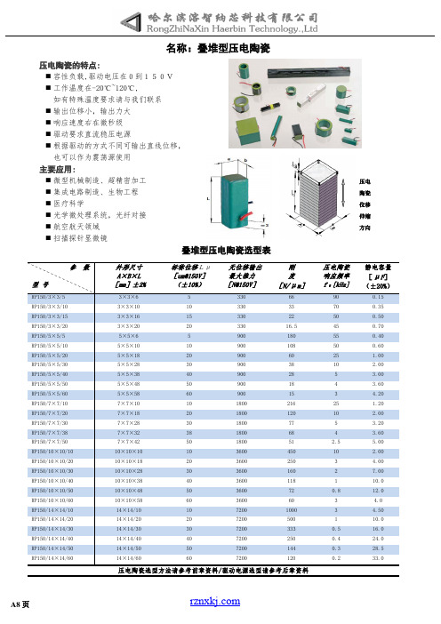
压电陶瓷PZT型号
-50 V~+200V
■
pst 150 系列 0V~+150V 的电压与位移曲线
■
pst 150 系列-30 V~+150V 的电压与位移曲线
Pst-HD 200 系列 0V~+150V 的电压与位移曲线 Pst-HD 200 系列-30 V~+150 的电压与位移曲线
50
7200
144
14×14/60
60
7200
120
压电陶瓷选型方法请参考前章资料/驱动电源选型请参考后章资料
压电 陶瓷 位移 伸缩 方向
压电陶瓷 响应频率 f 0 [kHz]
90 70 50 45 55 50 25 10 5 4 3 25 10 5 4 2.5 10 3 2 1 0.8 3 3 1 0.5 0.4 0.3 0.2
工作原理 该产品是由两片相同的沿厚度方向极化的压电陶瓷片粘接而成,将致动器一端固定,构成悬臂梁结构,沿 Z 方向
施加电场,压电陶瓷双晶片一片收缩,另一片伸长,变形方向可以通过改变正负极连线来控制,压电陶瓷片非固定端便 可以发生弯曲变形。
具体用途 低负载(一般从几克到几十克)、大位移(可达几 mm)如:选针器、盲人阅读器、压电泵、电子锁、摄像机快门、
静电容量 [nF]
80 335 320 47 46 74 84 204 38 10 44
工作动态图
外形尺寸图
电气接线图
备注: 除上述规格外,我公司也可以根据客户要求定制
A11 页
名称:光纤拉伸-压电陶瓷
环形压电陶瓷的特点 多层共烧一体 轴向响应频率大 d31 和 d33 可靠运行 在力传感器/发电机中的广泛应用 小的驱动电压到 50 V 可以驱动非常高负荷 温度范围:-273°C ~ + 130°C 表面绝缘:镀银电极,表面无涂层
6N134中文资料

6N134中⽂资料FeaturesDual Marked with Device Part Number and DSCC Drawing NumberManufactured and Tested on a MIL-PRF-38534 Certified LineQML-38534, Class H and K Five Hermetically Sealed Package Configurations Performance Guaranteed over -55°C to +125°C ? High Speed: 10 M Bit/sCMR: > 10,000 V/µs Typical 1500 Vdc Withstand Test Voltage2500 Vdc Withstand Test Voltage for HCPL-565X High Radiation Immunity 6N137, HCPL-2601, HCPL-2630/-31 Function Compatibility ? Reliability DataTTL Circuit CompatibilityApplicationsMilitary and SpaceHigh Reliability SystemsTransportation, Medical, and Life Critical SystemsLine ReceiverVoltage Level ShiftingIsolated Input Line Receiver Isolated Output Line Driver Logic Ground Isolation Harsh Industrial EnvironmentsIsolation for Computer,Communication, and Test Equipment SystemsDescriptionThese units are single, dual and quad channel, hermetically sealed optocouplers. The products are capable of operation and storage over the full military temperature range and can be purchased as either standard product or with full MIL-PRF-38534 Class Level H or K testing or from the appropri-ate DSCC Drawing. All devices are manufactured and tested on a MIL-PRF-38534 certified line and are included in the DSCC Quali-fied Manufacturers List QML-38534 for Hybrid Microcircuits.Quad channel devices areavailable by special order in the 16 pin DIP through hole packages.Truth Table(Positive Logic)Multichannel DevicesInput Output On (H)L Off (L)HFunctional DiagramMultiple Channel Devices AvailableSingle Channel DIP Input Enable Output On (H)H L Off (L)H H On (H)L H Off (L)LH*See matrix for available extensions.Hermetically Sealed, High Speed,High CMR, Logic Gate Optocouplers Technical Data6N134*81028HCPL-563X HCPL-663X HCPL-565X 5962-98001HCPL-268K HCPL-665X 5962-90855HCPL-560XCAUTION: It is advised that normal static precautions be taken in handling and assembly of this component to prevent damage and/or degradation which may be induced by ESD.V CC V OUTV E GNDThe connection of a 0.1 µF bypass capacitor between V CC and GND is recommended.Selection Guide–Package Styles and Lead Configuration OptionsPackage16 Pin DIP 8 Pin DIP 8 Pin DIP 8 Pin DIP 16 Pin Flat Pack 20 Pad LCCC Lead Style Through Hole Through Hole Through Hole Through Hole Unformed Leads Surface MountChannels 212242Common Channel V CC , GND None V CC , GND V CC , GND V CC , GND None WiringWithstand Test Voltage 1500 Vdc 1500 Vdc 1500 Vdc 2500 Vdc 1500 Vdc 1500 Vdc Agilent Part # & Options Commercial6N134*HCPL-5600HCPL-5630HCPL-5650HCPL-6650HCPL-6630MIL-PRF-38534, Class H 6N134/883BHCPL-5601HCPL-5631HCPL-5651HCPL-6651HCPL-6631MIL-PRF-38534, Class K HCPL-268K HCPL-560K HCPL-563K HCPL-665K HCPL-663K Standard Lead Finish Gold Plate Gold Plate Gold Plate Gold Plate Gold PlateSolder PadsSolder Dipped Option #200Option #200Option #200Option #200Butt Cut/Gold Plate Option #100Option #100Option #100Gull Wing/Soldered Option #300Option #300Option #300Class H SMD Part #Prescript for all below None 5962-None None None None Either Gold or Solder 8102801EX 9085501HPX 8102802PX 8102805PX 8102804FX 81028032XGold Plate 8102801EC 9085501HPC 8102802PC 8102805PC 8102804FCSolder Dipped 8102801EA 9085501HPA 8102802PA 8102805PA81028032A Butt Cut/Gold Plate 8102801UC 9085501HYC 8102802YC Butt Cut/Soldered 8102801UA 9085501HYA 8102802YA Gull Wing/Soldered 8102801TA 9085501HXA8102802ZA Class K SMD Part #Prescript for all below 5962-5962-5962-5962-5962-Either Gold or Solder 9800101KEX 9085501KPX 9800102KPX 9800104KFX 9800103K2XGold Plate 9800101KEC 9085501KPC 9800102KPC 9800104KFCSolder Dipped 9800101KEA 9085501KPA 9800102KPA 9800103K2AButt Cut/Gold Plate 9800101KUC 9085501KYC 9800102KYC Butt Cut/Soldered 9800101KUA 9085501KYA 9800102KYA Gull Wing/Soldered9800101KTA 9085501KXA 9800102KZA*JEDEC registered part.Each channel contains a GaAsP light emitting diode which isoptically coupled to an integrated high speed photon detector. The output of the detector is an open collector Schottky clamped transistor. Internal shields provide a guaranteed common mode transient immunityspecification of 1000 V/µs. For Isolation Voltage applications requiring up to 2500 Vdc, the HCPL-5650 family is also available. Package styles for these parts are 8 and 16 pin DIP through hole (case outlines P andE respectively), and 16 pin surface mount DIP flat pack(case outline F), leadless ceramic chip carrier (case outline 2).Devices may be purchased with a variety of lead bend and plating options. See Selection Guide Table for details. Standard Microcircuit Drawing (SMD)parts are available for each package and lead style.Because the same electrical die (emitters and detectors) are used for each channel of each device listed in this data sheet, absolute maximum ratings, recommended operating conditions, electrical specifications, and performance characteristics shown in the figures are identical for all parts.Occasional exceptions exist due to package variations and limitations,and are as noted. Additionally, the same package assembly processes and materials are used in all devices. These similarities give justification for the use of data obtained from one part torepresent other parts’ performance for reliability and certain limited radiation test results.Outline Drawings16 Pin DIP Through Hole, 2 ChannelsFunctional DiagramsNote: All DIP and flat pack devices have common V CC and ground. Single channel DIP has an enable pin 7. LCCC (leadless ceramic chip carrier) package has isolated channels with separate VCC and ground connections. All diagrams are “top view.”Leaded Device MarkingLeadless Device MarkingNOTE: DIMENSIONS IN MILLIMETERS (INCHES).COMPLIANCE INDICATOR,*DATE CODE, SUFFIX (IF NEEDED)COUNTRY OF MFR.Agilent CAGE CODE*Agilent DESIGNATORDSCC SMD*PIN ONE/ ESD IDENTAgilent P/N DSCC SMD** QUALIFIED PARTS ONLYCOMPLIANCE INDICATOR,*DATE CODE, SUFFIX (IF NEEDED)DSCC SMD*Agilent CAGE CODE*Agilent DESIGNATORCOUNTRY OF MFR.Agilent P/N PIN ONE/ ESD IDENTDSCC SMD** QUALIFIED PARTS ONLYOutline Drawings (continued)16 Pin Flat Pack, 4 Channels8 Pin DIP Through Hole, 2 Channels 2500 Vdc Withstand Test Voltage20 Terminal LCCC Surface Mount,2Channels8 Pin DIP Through Hole, 1 and 2 Channels0.36 (0.014)NOTE: DIMENSIONS IN MILLIMETERS (INCHES).2.29 (0.090) 2.79 (0.110)NOTE: DIMENSIONS IN MILLIMETERS (INCHES).NOTE: DIMENSIONS IN MILLIMETERS (INCHES).NOTE: DIMENSIONS IN MILLIMETERS (INCHES). SOLDER THICKNESS 0.127 (0.005) MAX.Hermetic Optocoupler OptionsRecommended Operating ConditionsParameterSymbol Min.Max.Units Input Current, Low Level, Each Channel I FL 0250µA Input Current, High Level, Each Channel*I FH 1020mA Supply Voltage, OutputV CC 4.55.5VFan Out (TTL Load) Each ChannelN6*Meets or exceeds DSCC SMD and JEDEC requirements.Absolute Maximum Ratings(No derating required up to +125°C)Storage Temperature Range, T S ...................................-65°C to +150°C Operating Temperature, T A..........................................-55°C to +125°C Case Temperature, T C ................................................................+170°C Junction Temperature, T J ...........................................................+175°C Lead Solder Temperature ...............................................260°C for 10 s Peak Forward Input Current, I F PK , (each channel,≤1 ms duration)......................................................................40 mA Average Input Forward Current, I F AVG (each channel)................20 mA Input Power Dissipation (each channel).....................................35 mW Reverse Input Voltage, V R (each channel).........................................5 V Supply Voltage, V CC (1 minute maximum)........................................7 V Output Current, I O (each channel)...............................................25 mA Output Power Dissipation (each channel). (40)mW Output Voltage, V O (each channel)..................................................7 V*Package Power Dissipation, P D (each channel)........................200 mW*Selection for higher output voltages up to 20 V is available.Single Channel Product OnlyEmitter Input Voltage, V E ...............................................................5.5 VNote enable pin 7. An external 0.01 µF to 0.1 µF bypass capacitor must be connected between V CC and ground for each package type.8 Pin Ceramic DIP Single Channel SchematicESD Classification(MIL-STD-883, Method 3015)HCPL-5600/01/0K ...............................................................(?), Class 16N134, 6N134/883B, HCPL-5630/31/3K, HCPL-5650/51, HCPL-6630/31/3K and HCPL-6650/51/5K.......................(Dot), Class 3Electrical Characteristics (T= -55°C to +125°C, unless otherwise specified)*Identified test parameters for JEDEC registered parts.**All typical values are at V CC = 5 V , T A = 25°C. Recommended Operating Conditions (cont’d.)Single Channel Product Only [10]ParameterSymbol Min.Max.Units High Level Enable Voltage V EH 2.0V CC V Low Level Enable VoltageV EL0.8VElectrical Characteristics, (Contd.) T= -55°C to +125°C unless otherwise specifiedSingle Channel Product Only Low Level I EL V CC = 5.5 V,1, 2, 3-1.45-2.0mA Enable Current V E = 0.5 V High Level V EH 1, 2, 3 2.0V10Enable Voltage Low Level V EL 1, 2, 30.8VEnable Voltage*Identified test parameters for JEDEC registered part.**All typical values are at V CC = 5 V , T A = 25°C.Typical Characteristics, T = 25°C, V = 5 VDual and Quad Channel Product Only Input-Input I I-I 0.5nA Relative Humidity = 45%4Leakage CurrentV I-I = 500 V, t = 5 s Resistance (Input-Input)R I-I 1012V I-I = 500 V 4Capacitance (Input-Input)C I-I0.55pF f = 1 MHz4Notes:1. Each channel.2. All devices are considered two-terminal devices; I I-O is measured between all input leads or terminals shorted together and alloutput leads or terminals shorted together.3. Measured between each input pair shorted together and all output connections for that channel shorted together.4. Measured between adjacent input pairs shorted together for each multichannel device.5. t PHL propagation delay is measured from the 50% point on the leading edge of the input pulse to the 1.5 V point on the leadingedge of the output pulse. The t PLH propagation delay is measured from the 50% point on the trailing edge of the input pulse to the1.5 V point on the trailing edge of the output pulse.6. The HCPL-6630, HCPL-6631, and HCPL-663K dual channel parts function as two independent single channel units. Use the singlechannel parameter limits for each channel.7. CM L is the maximum rate of rise of the common mode voltage that can be sustained with the output voltage in the logic low state(V O < 0.8 V). CM H is the maximum rate of fall of the common mode voltage that can be sustained with the output voltage in the logic high state (V O > 2.0 V).8. This is a momentary withstand test, not an operating condition.9. It is essential that a bypass capacitor (0.01 to 0.1 µF, ceramic) be connected from V CC to ground. Total lead length between bothends of this external capacitor and the isolator connections should not exceed 20 mm.10. No external pull up is required for a high logic state on the enable input.11. The t ELH enable propagation delay is measured from the 1.5 V point on the trailing edge of the enable input pulse to the 1.5 Vpoint on the trailing edge of the output pulse.12. The t EHL enable propagation delay is measured from the 1.5 V point on the leading edge of the enable input pulse tothe 1.5 Vpoint on the leading edge of the output pulse.13. Standard parts receive 100% testing at 25°C (Subgroups 1 and 9). SMD and 883B parts receive 100% testing at 25, 125, and-55°C (Subgroups 1 and 9, 2 and 10, 3 and 11, respectively).14. Parameters are tested as part of device initial characterization and after design and process changes. Parameters are guaranteedto limits specified for all lots not specifically tested.15. Not required for 6N134, 6N134/883B, 8102801, HCPL-268K and 5962-9800101 types.16. Required for 6N134, 6N134/883B, 8102801, HCPL-268K and 5962-9800101 types.17. Not required for HCPL-5650, HCPL-5651 and 8102805 types.18. Required for HCPL-5650, HCPL-5651 and 8102805 types only.Figure 1. High Level Output Currentvs. Temperature.5 VV O * C L INCLUDES PROBE AND STRAY WIRING CAPACITANCE. Figure 4. Test Circuit for t PHL and t PLH .*I +5 V OUTPUT V O MONITORING NODEFigure 7. Test Circuit for Common Mode Transient Immunity and Typical Waveforms.11OUTPUT V OMONITORINGNODET A = +125 °C* ALL CHANNELS TESTED SIMULTANEOUSLY.V CCI O = 25 mAFigure 10. Operating Circuit for Burn-In and Steady State Life Tests. Figure 8. Test Circuit for t EHL and t ELH.Figure 9. Enable Propagation Delayvs. Temperature.MIL-PRF-38534 Class H,Class K, and DSCC SMDTest ProgramAgilent’s Hi-Rel Optocouplers arein compliance with MIL-PRF-38534 Classes H and K. Class Hand Class K devices are also incompliance with DSCC drawings81028, 5962-90855 and 5962-98001.Testing consists of 100% screen-ing and quality conformanceinspection to MIL-PRF-38534./doc/4e2d970a03d8ce2f006623a8.htmlData subject to change.Copyright ? 1999 Agilent TechnologiesObsoletes 5968-4743E5968-9407E (10/00)。
JASO D618-2013(翻译中文版)

从电线取长度 350 mm 以上的样品,剥云两端大约 25 mm 的绝缘,让导体露出,将两端扭绞在一起。
6.2.2.2 装置
盛满能将环状试样中间部分约 300 mm 浸入容量盐水的非导电容器(氯化钠质量比 3 %);50 Hz 或 60
Hz、能够调压的最大 5 kV(有效值)的交流电源。
6.2.2.3 步骤
2013表1电线类型类型名称标记适用标准汽车用聚氯乙烯绝缘低压电线avhebhdebjasod611汽车用无卤绝缘低压电线hfjasod611汽车用厚壁铝低压电线aljasod603薄壁1汽车用薄壁低压电线1avsjasod611薄壁2汽车用薄壁低压电线2avsscavscavjasod611汽车用极薄壁无卤绝缘低压电线hfssjasod611汽车用压缩导体极薄壁无卤绝缘低压电线chfsjasod611汽车用薄壁铝低压电线alssjasod603薄壁3汽车用薄壁低压电线3cavusjasod611汽车用压缩导体超薄壁无卤绝缘低压电线chfusjasod611汽车用超薄壁铝低压电线alusjasod603汽车用压缩导体超薄壁聚氯乙烯绝缘低压电线civus接地用汽车用接地低压电线ebjasod611耐热1汽车用交联聚氯乙烯绝缘耐热低压电线avxavfxhebxjasod611薄壁1汽车用薄壁型交联聚氯乙烯绝缘耐热低压电线avsxavxsjasod611薄壁2汽车用极薄壁型交联聚氯乙烯绝缘耐热低压电线avssxjasod611汽车用极薄壁型聚氯乙烯绝缘耐热低压电线avsshjasod611汽车用极薄壁型聚氯乙烯绝缘耐热低压电线ivssh接地用汽车用交联聚氯乙烯绝缘耐热接地低压电线ebxjasod611耐热2汽车用交联聚乙烯绝缘耐热低压电线aexjasod611薄壁2汽车用极薄壁型交联聚乙烯绝缘耐热低压电线aessxjasod611jisc3406中没有规定的结构
凡甲产品资讯

凡甲电子(苏州)有限公司
USB 2.0 CONNECTOR
• ALLTOP SERIES C107 • PHITCH 2.0/2.5mm, 4PIN • TEPY Straight Right Angle SMT DIP MINI MICRO
USB 3.0 CONNECTOR
• ALLTOP SERIES C190 • PHITCH 2.0/2.5mm, 9PIN • TEPY Straight Right Angle SMT DIP MINI MICRO
• ALLTOP SERIES C995 C996
• RATING :Power 50A max@2000V ac, Signal 3A max@500V ac CERTIFICATIONS : UL/CSA/ETC
POWER TEN 60 CONNECTOR
ALLTOP SERIES C225 C226
凡甲电子(苏州)有限公司
D-SUB CONNECTOR
• ALLTOP SERIES C105 • PHITCH 1.145mm, 15PIN • TEPY Right Angle DIP
DVI CONNECTOR
• ALLTOP SERIES C162 C182 • PHITCH 1.905mm, 24PIN • TEPY Right Angle DIP
DIN 41612 CONNECTOR
• ALLTOP SERIES C993 C994 • PHITCH 2.54mm
• RATING: Signal@2A,Power@up to 11A CERTIFICATIONS UL/CSA/TUV
凡甲电子(苏州)有限公司
INFINITY HIGH POWER CONNECTOR
P8P中文资料
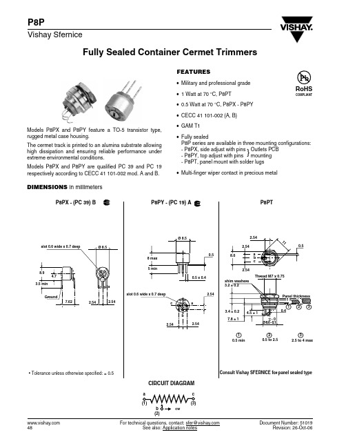
Fully Sealed Container Cermet Trimmers For technical questions, contact: sfer@See also: Application notesDocument Number: 5101948Revision: 26-Oct-06P8PVishay SferniceFEATURES•Military and professional grade •1 Watt at 70 °C, P8PT•0.5 Watt at 70 °C, P8PX - P8PY •CECC 41 101-002 (A, B)•GAM T1•Fully sealedP8P series are available in three mounting configurations:- P8PX, side adjust with pins - P8PY, top adjust with pins - P8PT, panel mount with solder lugs•Multi-finger wiper contact in precious metalModels P8PX and P8PY feature a TO-5 transistor type,rugged metal case housing.The cermet track is printed to an alumina substrate allowing high dissipation and ensuring reliable performance under extreme environmental conditions.Models P8PX and P8PY are qualified PC 39 and PC 19respectively according to CECC 41 101-002 mod. A and B.DIMENSIONS in millimetersP8PX - (PC 39) B• Tolerance unless otherwise specified: ± 0.5P8PTCIRCUIT DIAGRAM}Outlets PCB mountingDocument Number: 51019For technical questions, contact: sfer@See also: Application notes Revision: 26-Oct-0649P8PFully Sealed Container Cermet TrimmersVishay SferniceELECTRICAL SPECIFICATIONSResistive Element cermet Electrical Travel 270° ± 15°Resistance Range 10 Ω to 2.2 M ΩStandard series E3 1 - 2.2 - 4.7 and on request 1 - 2 - 5Tolerance Standard ± 10 %On Request ± 5 %Power RatingP8PX - P8PY 0.5 W at 70 °C P8PT1 W at 70 °CTemperature CoefficientSee Standard Resistance Element T ableLimiting Element Voltage (Linear Law)250 VContact Resistance Variation 2 % Rn or 1 ΩEnd Resistance (Typical) 1 Ω Dielectric Strength (RMS)1000 V Insulation Resistance (500 VDC)1 GΩMECHANICAL SPECIFICATIONSMechanical Travel300° ± 5°Operating Torque (max. Ncm)3End Stop Torque (max. Ncm)6Unit Weight (max. g)1... 3.1ENVIRONMENTAL SPECIFICATIONSTemperature Range - 55 °C to + 125 °C Climatic Category 55/125/56Sealingfully sealed container IP67POWER RATING CHARTPERFORMANCECECC 41100TYPICAL VALUES AND DRIFTS TESTSCONDITIONSΔRTRT (%)REQUIREMENTS ΔR 1-2R 1-2(%) ΔRTRT (%) ΔR 1-2R 1-2(%)Climatic SequencePhase A dry heat 125 °C Phase B damp heat Phase C cold - 55 °CPhase D damp heat 5 cycles± 2 %± 3 %± 0.5 %± 1 %Long Term Damp Heat56 days 40 °C, 93 % RH ± 2 %± 3 %± 0.5 %± 1 %Dielectric strength: 700 VInsulation resistance: > 100 M ΩDielectric strength: 1000 V Insulation resistance: > 104 M ΩRotational Life 200 cycles± 2 %± 1 %Contact res. variat.: < 5 % Rn Contact res. variat.: < 2 % Rn Load Life1000 h at rated power 90’/30’ - ambient temp. 70 °C± 2 %± 3 %± 1 %± 2 %Contact res. variat.: < 5 % Rn Contact res. variat.: < 1 % Rn Rapid Temperature Change 5 cycles- 55 °C to + 125 °C ± 1.5 %ΔV 1-2V 1-3≤ ± 1 %± 0.2 %ΔV 1-2V 1-3≤ ± 0.5 %Shock50 g at 11 m secs 3 successive shocks in 3 directions ± 1 %± 2 %± 0.1 %± 0.5 %Vibration 10 - 55 Hz 0.75 mm or 10 g during 6 hours± 1 %ΔV 1-2V 1-3≤ ± 2 %± 0.2 %ΔV 1-2V6≤ ± 0.5 % For technical questions, contact: sfer@See also: Application notesDocument Number: 5101950Revision: 26-Oct-06P8PVishay SferniceFully Sealed Container Cermet TrimmersSTANDARD RESISTANCE ELEMENT DATASTANDARD RESISTANCE VALUESP8PX - P8PYP8PT TCR - 55 °C + 125 °C MAX.POWER AT 70 °CMAX.WORKING VOLTAGEMAX. CUR.THROUGH WIPERMAX.POWER AT 70 °CMAX.WORKING VOLTAGEMAX. CUR.THROUGH WIPERΩW V mA W V mA ppm/°C 102247 0.52.23.34.822415010313.164.696.863162131460+ 2001002204701K 2.2K 4.7K 10K 22K 47K 100K 220K 470K 1M 2.2M0.50.280.130.060.028710.515.322.433.248.57.710515322425025025025070473222151074.83.22.21.11.530.250.1110.630.280.130.060.0310.014.821.731.646.968.6100.0148217250250250250250100674632211510.06.74.62.51.10.50.30.1± 100MARKINGPrinted :- VISHAY trademark - NF type if applicable - series - style- ohmic value (in Ω , k Ω, M Ω)- tolerance (in %)- manufacturing date - marking of terminal: 3PACKAGING- Plastic box of 50 pieces for P8PX and P8PY - Plastic box of 24 pieces for P8PTORDERING INFORMATIONP8MODEL PY STYLE 10 k ΩOHMIC VALUE ± 10 %TOLERANCE BL50PACKAGING e2LEAD FINISHP8PX and P8PY: BL50P8PT: BL24e2: SnAg alloyDocument Number: 91000Revision: 18-Jul-081DisclaimerLegal Disclaimer NoticeVishayAll product specifications and data are subject to change without notice.Vishay Intertechnology, Inc., its affiliates, agents, and employees, and all persons acting on its or their behalf (collectively, “Vishay”), disclaim any and all liability for any errors, inaccuracies or incompleteness contained herein or in any other disclosure relating to any product.Vishay disclaims any and all liability arising out of the use or application of any product described herein or of any information provided herein to the maximum extent permitted by law. The product specifications do not expand or otherwise modify Vishay’s terms and conditions of purchase, including but not limited to the warranty expressed therein, which apply to these products.No license, express or implied, by estoppel or otherwise, to any intellectual property rights is granted by this document or by any conduct of Vishay.The products shown herein are not designed for use in medical, life-saving, or life-sustaining applications unless otherwise expressly indicated. Customers using or selling Vishay products not expressly indicated for use in such applications do so entirely at their own risk and agree to fully indemnify Vishay for any damages arising or resulting from such use or sale. Please contact authorized Vishay personnel to obtain written terms and conditions regarding products designed for such applications.Product names and markings noted herein may be trademarks of their respective owners.元器件交易网。
FDG6316中文资料

Features
• –0.7 A, –12 V. RDS(ON) = 270 mΩ @ VGS = –4.5 V RDS(ON) = 360 mΩ @ VGS = –2.5 V RDS(ON) = 650 mΩ @ VGS = –1.8 V
Applications
• Battery management • Load switch
2. Pulse Test: Pulse Width < 300µs, Duty Cycle < 2.0%
FDG6316P Rev D (W)
元器件交易网
FDG6316P
Typical Characteristics
2
3 RDS(ON), NORMALIZED DRAIN-SOURCE ON-RESISTANCE
(Note 2)
VDS = –6 V, f = 1.0 MHz
V GS = 0 V,
146 60 48
pF pF pF 10 23 16 4 2.4 ns ns ns ns nC nC nC –0.25 A V
Switching Characteristics
Turn–On Delay Time Turn–On Rise Time Turn–Off Delay Time Turn–Off Fall Time Total Gate Charge Gate–Source Charge Gate–Drain Charge
the drain pins. RθJC is guaranteed by design while RθJA is determined by the user's board design. RθJA = 415°C/W when mounted on a minimum pad of FR-4
PSL631说明书

4.4 输出接点 ..................................................................................................................................... 24 4.5 结构与安装 ................................................................................................................................. 25 4.6 各插件原理说明 ........................................................................................ 26 5 PSL 631C定值清单及整定说明.....................................................................................................35 5.1 断路器保护定值清单及整定说明 ............................................................................................. 35 5.2 重合闸定值清单及整定说明 ..................................................................................................... 36 5.3 压板定值 ..................................................................................................................................... 38
汉钟螺杆压缩机产品说明书 - RC系列

CNC Cutter Measuring System
High Efficiency Motor
CNC Cutter Sharpener
Machine
Premium-grade low-loss core steel with the special RC motor cooling slot design
+5°F ~ +59°F -15°C ~ +15°C
R22 R134a R407C R404A R507
NSourtphpAblimyederinica
Compressor
Description
Displacement @ 60 Hz. Displacement @ 50 Hz. Rated Speed Volume Ratios Available Capacity Control System Refrigerant Lubrication Oil Heater Wattage Lubricant Type
2734 1240
3 Phase, 2 Pole, Induction Motor
YD Starting ~ (60Hz. and 50Hz.)
460/3/60, 575/3/60 - Standard
380/3/50, 400/3/50, 415/3/50 Class F
PTC Protection
195.8 156.6 15.0 237.0 166.4 17.1 177.9 181.6 11.8 216.1 192.8 13.4
256.1 202.7 15.2 310.0 215.4 17.3 232.7 234.9 11.9 282.6 250.3 13.6
631-632说明书
19>。绝缘电阻符合IEC255-5标准100MΩ/500V
20>。耐压测试IEC255-5标准2.0KV/50Hz/1min
21>。脉冲电压测试IEC-255-5标准5KV/1.2/50μS/0.5J
22>。抗干扰
【1】共模干扰IEC255-22-1标准2.5KV/1MHz/2S
df/dt频率的变化率,df滑差整定值
U母线电压,DYD低电压闭锁定值,软件定义50V,无需整定
DL断路器状态
单相接地跳闸或选线
当中性点经电阻接地或零序电流较大时应直接作用于跳闸
I0I0D
TI0S
I0实测零序电流值,I0D零序电流动作整定值
T延时时间,I0S零序延时整定值
当中性点不接地或经消弧线圈接地,若零序电流较小不需跳闸时,装置自动识别线路零序电流5次谐波的功率方向为正且经CAN通讯网确认本线路零序电流值最大时发单相接地予报信号。(CAN总线为无主站系统,可实现任意装置间的通讯)
控制部分由遥控跳合闸、手动跳合闸及防跳回路组成。
测量部分由电流测量、电压测量、频率测量、功率测量、功率因数测量、电度测量组成。
监视部分配有装置故障报警、保护定值不合理报警、控制回路断线报警、PT断线报警及每种保护动作的独立信号空接点输出。
CAN总线网络控制部分实现装置同网络上其它设备间进行实时的数据交换。完成遥测、遥信、遥控、遥调及远方修改保护定值、远方信号复归等功能,直接构成发电厂、变电站综合自动化系统。
【2】电气测量
三相电流、电压、有功及无功功率、功率因数、频率、有功电度及无功电度。
开关事件记录
直接记录外部8个开关状态事件的时间及顺序并对脉冲计数,对不同的应用8个开关状态定义可以不同。
1730638资料

Extract from the online catalogThe illustration shows a 12-position version Printed circuit terminal block, nominal current: 12 A, rated voltage: 250 V, pitch: 5.08 mm, no. of positions: 4, mounting: Press in, type of connection: Screw connection, connection direction from the conductor to the PCB: 0°Order No.1730638Ord designation EMKDS 2,5/ 4-5,08 Catalog page information Page 19 (CC-2005) Technical dataTightening torque, min 0.5 NmTechnical dataInsulating material group IRated surge voltage (III/3) 2.5 kV Rated surge voltage (III/2) 2.5 kV Rated surge voltage (II/2) 2.5 kV Rated voltage (III/2) 320 V Rated voltage (II/2) 630 V Connection in acc. with standard EN-VDE12 A Nominal current IN250 V Nominal voltage UNNominal cross section 2.5 mm²Maximum load current 12 A Insulating material PA Inflammability class acc. to UL 94 V0 Internal cylindrical gage A3 Stripping length 8 mm Connection dataConductor cross section, rigid min. 0.14 mm²Conductor cross section, rigid max. 2.5 mm²Conductor cross section flexible min. 0.14 mm²Conductor cross section, flexible max. 2.5 mm²0.25 mm²Conductor cross section flexible, with ferrule withoutplastic sleeve min.Conductor cross section flexible, with ferrule without2.5 mm²plastic sleeve max.0.25 mm²Conductor cross section flexible, with ferrule with plasticsleeve min.1.5 mm²Conductor cross section flexible, with ferrule with plasticsleeve max.Conductor cross section AWG/kcmil min. 26 Conductor cross section AWG/kcmil max 162 conductors with same cross section, solid min. 0.14 mm²2 conductors with same cross section, solid max. 0.75 mm²2 conductors with same cross section, flexible, min. 0.14 mm²2 conductors with same cross section, flexible max. 0.75 mm²0.25 mm²2 conductors with same cross section, flexible, ferruleswithout plastic sleeve min.0.5 mm²2 conductors with same cross section, flexible, ferruleswithout plastic sleeve, max.2 conductors with same cross section, flexible, TWIN0.5 mm²ferrules with plastic sleeve, min.2 conductors with identical cross section, flexible TWIN1.5 mm²ferrules with plastic sleeve, max.CertificatesCSA300 V Nominal voltage UN10 A Nominal current INAWG/kcmil 28-12 CUL300 V Nominal voltage UNNominal current I10 ANAWG/kcmil 30-12 UL300 V Nominal voltage UNNominal current I10 ANAWG/kcmil 30-12Drawings Drilling diagramDimensioned drawingApproval logoAccessoriesItem Designation DescriptionMarking0804293SK 5,08/3,8:FORTL.ZAHLEN Marker card, printed horizontally, self-adhesive, 12 identicaldecades marked 1-10, 11-20 etc. up to 91-(99)100, sufficient for120 terminal blocksTools1205053SZS 0,6X3,5Screwdriver, bladed, matches all screw terminal blocks up to 4.0mm² connection cross section, blade: 0.6 x 3.5 mm, without VDEapprovalAddressPHOENIX CONTACT Inc., USA 586 Fulling Mill Road Middletown, PA 17057USAPhone (800) 888-7388Fax (717) 944-1625 Phoenix ContactTechnical modifications reserved;。
德力西低压配电箱系列

303
383
暗装(箱体尺寸)
A
B
163
200
199
200
272
200
343
200
413
200
282
364
厚度 C 90 90 90 90 90 90
产品位数
6 9 12 15
明装(箱体尺寸)
A
B
217
214
271
214
325
214
372
214
暗装(箱体尺寸)
A
B
188
191
242
191
296
191
352
Delixi Electric
CDPZ30 照明配电箱
技术参数
阻燃塑料门,可向上开启90° 额定工作电压:230/400V AC 短时耐受电流:4.5kA 最大额定工作电流:100A 材料 面板采用冷轧钢板制造,表面通过静电喷塑技术处理,坚固耐用 塑料小门,采用透明树苯材料,门框采用阻燃ABS材料,防火自熄 底箱:采用冷轧钢板制造,表面通过静电喷塑或镀锌处理,防腐蚀效果好 防护等级:IP30 安装及布线: 底箱周围有敲落孔,便于进出线 底箱与导轨间有间距,满足客户底部布线需求 可在垂直方向调整导轨深度,准确安装 符合标准:GB7251 /GB17466
138 210 71 180 108 20 55 130 48
138 210 71 180 108 20 55 130 48
157 210 71 180 127 20 55 130 57
280 209 85 180 230 20 140 115 114
290 225 85 225 290 42.5 55 140 180
无锡小压缩机说明书

LGFD-3.6/7-X 型 LGFD-2.8/10-X 型LGFD-2.8/7-X 型 LGFD-3/10-X 型 LGFD-3/7-X 型固定式喷油螺杆压缩机使 用 说 明 书SM-2002 DC 、、B A、003003003003003无锡压缩机股份有限公司二○○二年一月用户须知1本说明书叙述如何操作LGFD-3.6/7-X型及其变型机组LGFD-2.8/10-X型、LGFD-2.8/7-X型、LGFD-3/10-X型、LGFD-3/7-X 型螺杆压缩机。
在安装及启动之前,应仔细阅读本说明书。
在充分了解机组各部分结构功用、使用维护保养方法以后,方可对机组进行正确使用和保养。
这对于延长使用寿命并使其处于良好的工作状态是极为重要的。
2本机切不可反转,电动机旋转方向必须与压缩机接筒上所示箭头方向一致。
3 机组无意外情况不允许按紧急停机按钮停机。
正常停机采用延时停机,即按下停机按钮后约20秒机组自行停机。
4 使用中应注意,机组在卸载过久停机保护后,如若供气压力降至机组加载压力时,机组会自行起动加载。
5 压缩机用润滑油不允许混用。
6 机组工作时,不允许松动和拆卸任何连接部件。
只有在切断电源和排空压力后,才可以做检修工作,以免被高温高压气体伤害。
7 油管路附近不得进行焊接,不能用烧焊或其他方法修改任何压力容器。
8 开车前须详细阅读机组上的《操作须知》,严格按规定要求做,并做好运转时间、保养效果、油耗量、修理项目及内容等记录。
9 由于产品结构的不断改进,一定时期后,本说明书所述内容将会与实际产品有所出入,尚希用户注意。
目录第一章机组技术特性 (3)第二章系统说明 (5)一、结构特征及工作原理二、气管路系统三、油管路系统四、冷凝水的排放系统五、调节系统六、电气系统第三章安装指南 (9)第四章操作指南 (10)一、开机前的准备工作二、机组启动三、机组工作运行四、停机五、安全保护项目及调整值六、机组正常工作条件及压差数据七、长期停机之处理方法第五章维修与保养 (12)一、维修保养周期二、润滑油规范及使用保养第六章故障及排除 (14)一、故障及排除方法二、调整与维修附图一:机组外形图 (19)附图二:电气原理图 (20)附表:低噪声喷油螺杆压缩机运转记录表 (22)第一章 压缩机技术特性本系列压缩机主要技术特性见下表: 名 称 低噪声喷油螺杆压缩机国家标准型号 LGFD-3/7-X L G F D -2.4/10-X L G F D -2.4/10-X L G F D -2.5/7-X L G F D -2.5/7-X 企业型号 LGFD22/003 L G F D 22/003AL G F D 18.5/003B LGFD22/003C LGFD18.5/003D企业代号 003 003A 003B 003C 003D型 式 固定单级风冷喷油螺杆压缩介质空气 容积流量(m 3/min) 3.6 2.83进气压力(MPa) 常压 排气压力(MPa) 0.7 1.0 0.7 1.0 0.7排气温度(℃) <110 驱动功率 (kW) <22<18.5 <22<18.5 驱动转速(r /min) 2940 2930 2940 2930冷却方式 风冷 传动方式联轴器直接传动转子公称直径(mm) 120 安全阀开启压力(MPa) 0.77 1.10 0.77 1.10 0.77型 号 Y 2180M-2TY 2160L -2T Y 2180M -2TY 2160L -2T功 率(kW) 22 18.5 22 18.5转 速(r /min) 2940 2930 2940 2930配套主电机 电 压(V) 380 型 号 Y90S-2 功 率(kW) 1.5 转 速(r /min) 2840 风扇电机电 压(V)380 噪 声dB(A) <80 机组净重(kg)850外形尺寸(长×宽×高)mm1350×1030×1255压缩机机组总图见图一 压缩机机组外形图见附图一第二章系统说明一、结构特征及工作原理(压缩机系统流程图见图二)本系列机组是压缩空气用,单级、喷油、风冷、由电机驱动的低噪声固定式小型螺杆压缩机。
湖南三德科技热值分析系列产品说明书

官方微信官方网站目 录SDAC6000(u)量热仪SDACM4000量热仪SDACM3100量热仪SDC712量热仪SDC715量热仪01-05热值分析系列020*********-11元素分析系列SDCHN536碳氢氮元素分析仪SDCH536红外碳氢仪SDH536红外测氢仪SDS350红外定硫仪SDS820自动定硫仪SDS720自动定硫仪SDS-V 定硫仪SDFCl3000自动氟氯分析仪SDFCl1000(a)氟氯分析仪070707080909101111SDTGA8000(a)工业分析仪SDTGA6000工业分析仪SDTGA6000A 工业分析仪SDTGA6000V 工业分析仪SDTGA5000a 工业分析仪SDTGA520(a)水分测试仪SDTGA500光波水分测试仪SDIMF200智能马弗炉SDMF300马弗炉SDIDB413智能干燥箱SDDH315通氮鼓风干燥箱SDDH323鼓风干燥箱SDDH313鼓风干燥箱SDDH306鼓风干燥箱12-22成分分析系列1314151516171819202121222222SDAF105(a /b )灰熔融性测试仪SDAF4000灰熔融性测试仪SDHG60a 哈氏可磨性指数测定仪23-26物理特性分析系列242526S DUC3150(D )联合制样机S DHD150t 锤式破碎缩分机S DHC锤式破碎机S DJC颚式破碎机S DRC对辊破碎机S DHCW400×260湿煤破碎机S DPP制样粉碎机S DMD16自动机械缩分器S DNS300环保振筛机S DNS200a标准振筛机S DRD二分器采制样辅助工具30-38样品制备系列313232333334343535353637-38激光盘料仪系列SDLM200便携式激光盘料仪SDLM1250固定式激光盘料仪39-41404142-43公司简介44发展历程45运维服务2829S DVD25风透 式快速除湿干燥系统S DVD3mm 风透 干燥机27-29风透 式低温快速除湿干燥系列热值分析系列适用范围符合标准GB/T213-2008GB/T384-1981 GB/T30727-2014ASTM D5865-2007ISO 1928-2009 JC/T1005-2006《煤的发热量测定方法》《石油产品热值测定法》《固体生物质燃料发热量测定方法》《煤与焦炭总热值的标准试验方法》《固体矿物燃料-氧弹式量热计测定总值并计算净热值》《水泥黑生料发热量测定方法》三德科技是中国第一台自动量热仪(1996年)的发明者,先后自主研发出6代量热仪,缔造了2个“国家重点新产品”。
山特维克长效空压机油产品说明书
1.1: 产品标识产品名称山特维克长效空压机油产品代码SANDVIK OC10-C1.2: 物质或混合物相关的确定的用途和禁止使用建议推荐用途液压油限制用途勿超出推荐的使用场合。
化学品及企业标识1.3: 安全技术说明书供应商详情生产企业 / 供应商山特维克矿山工程机械贸易(上海)有限公司地址上海市嘉定工业区兴荣路1200号8幢电子邮件地址********************1.4: 应急电话号码应急电话号码在化学急救事故发生时(泄漏,火灾,暴露或事故),拨打我们的服务提供商英国国家化学急救中心(NCEC ):欧洲: +44 1865 407 333巴西: +55 11 3197 5891美国: +1 202 464 2554墨西哥: +52 55 5004 8763非洲: +27 21 300 2732澳大利亚: +61 2 8014 4558新西兰: +64 9 929 1483中国 (大陆): + 86 532 8388 9090中国 (大陆以外): +86 512 8090 3042工作时间24小时/天,7天/周D V I K O C 10-C /C H N /ME T R I C © 山特维克矿山2017,瑞典和其他国家的山特维克拥有这个注册商标及其全部知识产权。
安全技术说明书山特维克高性能油品长效空压机油SANDVIK OC10-C根据法规(EC )第1907/2006(REACH )号第31条,修订的附录II 。
发布日期:2017年6月20日内部代码:SDS-SANDVIK OC10-C/CHN/METRIC3: 成分/组成信息4: 急救措施2.2: 标签要素EUH208: 含有成分 有机硫代磷酸盐. 可能产生致敏反应。
EUH210: 安全技术说明书方便索取。
4.1: 急救措施说明吸入供应新鲜空气,感到持续不适时要就医。
眼睛接触撑开眼睑时立即用大量水冲洗。
皮肤接触用肥皂和水冲洗。
南美豹空压机说明书
南美豹空压机说明书摘要:一、南美豹空压机简介二、南美豹空压机的主要功能与用途三、南美豹空压机的工作原理四、南美豹空压机的操作与维护五、南美豹空压机的适用行业与优势正文:一、南美豹空压机简介南美豹空压机是一款性能卓越、质量可靠的空气压缩设备。
该系列空压机在全球范围内享有较高的声誉,广泛应用于各个行业领域。
我国引进南美豹空压机后,其出色的性能和稳定的运行效率得到了用户的一致好评。
二、南美豹空压机的主要功能与用途南美豹空压机主要用于压缩空气,为各类气动设备提供动力。
此外,它还具有制冷、气体分离、气体输送等功能。
在电力、石油、化工、冶金、机械、纺织等行业中,南美豹空压机的应用极为广泛。
三、南美豹空压机的工作原理南美豹空压机采用往复活塞式、旋转叶片或旋转螺杆等技术,对空气进行压缩。
以螺杆空压机为例,其工作循环可分为进气、压缩和排气三个过程。
在进气过程中,外界空气通过进气口进入阴阳转子的齿沟内;在压缩过程中,阴阳转子相互啮合,将空气压缩;在排气过程中,压缩空气通过排气口排出。
四、南美豹空压机的操作与维护南美豹空压机的操作简单便捷,通过电动机驱动压缩机,实现活塞的往复运动。
在运行过程中,应定期检查机油量、冷却水流量、排气压力等参数,确保空压机在正常工作状态下运行。
同时,要定期清理空压机内部的杂质,以延长设备使用寿命。
五、南美豹空压机的适用行业与优势南美豹空压机适用于各种规模的企业和工厂,特别是在对空气压缩品质要求较高的场合。
南美豹空压机具有以下优势:1.高效节能:采用先进的螺杆式压缩技术,具有较高的压缩效率,节省能源消耗。
2.稳定可靠:运行稳定,故障率低,降低了维修成本。
3.噪音低:采用降噪设计,降低了空压机的运行噪音,有利于工作环境的改善。
4.智能化控制:配备智能控制系统,实现空压机的自动启停和故障报警等功能。
5.适应性强:南美豹空压机可适应各种恶劣环境,满足不同场景的需求。
总之,南美豹空压机凭借其优异的性能和实用的特点,成为了各领域用户的首选设备。
FDG型半封锁干式放电线圈技术参数
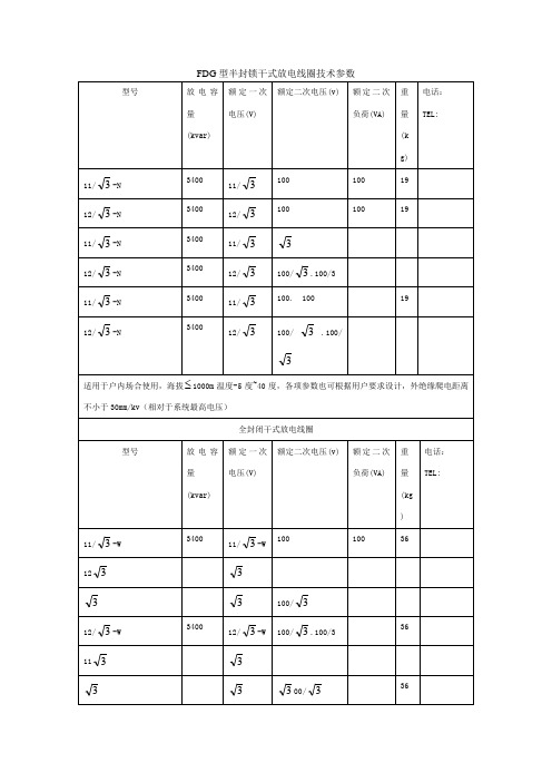
型号
放电容量
(kvar)
额定一次电压(V)
额定二次电压(v)
额定二次负荷(VA)
重量
(kg)
电话:
TEL:
11/ -W-1
3400
11/
100
100
19
12/ -W-1
3400
12/
100
100
19
11/ -W-1
3400
11/
100 100/
100
19
12/ -W-1
3400
12/
5000
6/
6/
100 100
100 100
36
适用于户内外各种场合使用,海拔 2000m,温度-25度~40度,各项参数也可根据用户要求设计,外绝缘爬电距离不小于50mm/kv(相对于系统最高电压)
100/ 100/3
19
11/ -W-1
3400
11/
100 100
100 100
19
12/ -W-1
3400
12/
100/ 100/
19
适用于户内外各种场合使用,海拔 2000m,温度-25度~40度,各项参数也可根据用户要求设计,外绝缘爬电距离不小于50mm/kv(相对于系统最高电压)
全封闭式差压式放电线圈
3400
11/
100. 100
19
12/ -N
3400
12/
100/ .100/
适用于户内场合使用,海拔 1000m温度-5度~40度,各项参数也可根据用户要求设计,外绝缘爬电距离不小于30mm/kv(相对于系统最高电压)
全封闭干式放电线圈
型号
Eaton PDG63P1600E4MN 电源防御型字型封装电路保护器数据手册说明书
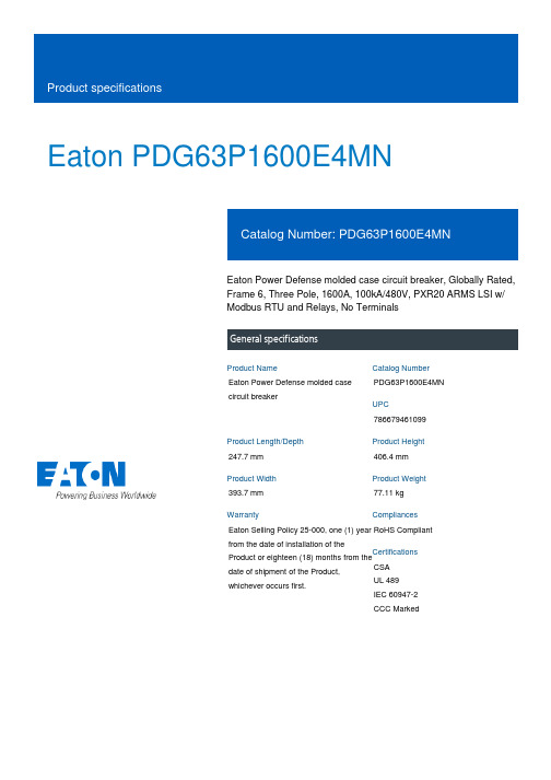
Eaton PDG63P1600E4MNEaton Power Defense molded case circuit breaker, Globally Rated, Frame 6, Three Pole, 1600A, 100kA/480V, PXR20 ARMS LSI w/ Modbus RTU and Relays, No TerminalsEaton Power Defense molded case circuit breakerPDG63P1600E4MN 786679461099247.7 mm 406.4 mm 393.7 mm 77.11 kg Eaton Selling Policy 25-000, one (1) year from the date of installation of theProduct or eighteen (18) months from thedate of shipment of the Product,whichever occurs first.RoHS Compliant CSAUL 489IEC 60947-2CCC MarkedProduct NameCatalog Number UPCProduct Length/Depth Product Height Product Width Product Weight WarrantyCompliancesCertifications1600 AComplete breaker 6Three-polePD6 Global Class A PXR 20 LSI w/ARMSModbus RTU600 Vac600 VNo Terminals100 kAIC at 480 Vac 200 kAIC @240V (UL)200 kAIC Icu/ 100 kAIC Ics/ 440 kAIC Icm @240V (IEC) 100 kAIC Icu/ 50 kAIC Ics/ 220 kAIC Icm @440V (IEC) 100 kAIC @480/277V (UL) 65 kAIC @600/347V (UL)100 kAIC Icu/ 50 kAIC Ics/ 220 kAIC Icm @380-415V (IEC) 40 kAIC Icu/ 25 kAIC Ics/ 84 kAIC Icm @525V South Africa (IEC)35 kAIC Icu/ 18 kAIC Ics/ 73.5 kAIC Icm @690V (IEC) 85 kAIC Icu/ 40 kAIC Ics/ 187 kAIC Icm @480V Brazil (IEC)1600 AEaton Power Defense PDG63P1600E4MN 3D drawingAmperage Rating Circuit breaker frame type Frame Number of poles Circuit breaker type Class Trip TypeCommunication Voltage rating Voltage rating - max Terminals Interrupt rating Interrupt rating range Trip rating 3D CAD drawing packageApplication notesPower Xpert Protection Manager x32Power Xpert Protection Manager x64Consulting application guide - molded case circuit breakersBrochuresPower Defense technical selling bookletPower Defense brochurePower Defense molded case circuit breaker selection posterCatalogsPower Xpert Release trip units for Power Defense molded case circuit breakersPower Defense molded case circuit breakers - Frame 6 product aid Molded case circuit breakers catalogCertification reportsEU Declaration of Conformity - Power Defense molded case circuit breakersPDG6 CSA certificationPDG6 CCC certificatePDG6 CB reportPDG5 CCC certificationPower Defense Declaration concerning California’s Proposition 65PDG6 UL AuthorizationInstallation instructionsPower Defense Frame 6 walking beam interlock installation instructions - IL012286ENPower Defense Frame 6 key interlock installation instructions -IL012282ENPower Defense Frame 6 handle lock hasp installation instructions -IL012292ENPower Defense Frame 6 bar rear connectors (copper), 2000A - 5000A instructions - IL012256EN H01Power Defense Frame 2/3/4/5/6 voltage neutral sensor module wiring instructions – IL012316ENPower Defense Frame 6 flex shaft handle mech assembly instructions - IL012285ENPower Defense Frame 6 tunnel terminal (aluminum), 2000A, 3 pole, imperial hardware instructions - IL012255EN H01Power Defense Frame 6 aux, alarm, shunt trip and uvr instructions -IL012202ENPower Defense Frame 6 modbus and relay board installation -IL012306ENInstallation videosPower Defense Frame 6 Aux, Alarm, ST and UVR Animated Instructions.rh Power Defense Frame 6 Trip Unit Replacement Animated Instructions Power Defense Frame 6 UVR Trip How-To VideoPower Defense Frame 6 Shunt Trip How-To VideoPower Defense Frame 6 Aux and Alarm Trip How-To Video MultimediaPower Defense Frame 3 Variable Depth Rotary Handle Mechanism Installation How-To VideoPower Defense BreakersPower Defense Frame 5 Trip Unit How-To VideoEaton Power Defense for superior arc flash safetyPower Defense Frame 6 Trip Unit How-To VideoPower Defense Frame 2 Variable Depth Rotary Handle Mechanism Installation How-To VideoPower Defense molded case circuit breakersSpecifications and datasheetsEaton Specification Sheet - PDG63P1600E4MNTime/current curvesPower Defense time current curve Frame 6 - PD6White papersSingle and double break MCCB performance revisitedIntelligent power starts with accurate, actionable dataIntelligent circuit protection yields space savingsMaking a better machineMolded case and low-voltage power circuit breaker health Implementation of arc flash mitigating solutions at industrial manufacturing facilitiesSafer by design: arc energy reduction techniquesMolded case and low-voltage breaker healthEaton Corporation plc Eaton House30 Pembroke Road Dublin 4, Ireland © 2023 Eaton. All Rights Reserved. Eaton is a registered trademark.All other trademarks areproperty of their respectiveowners./socialmedia。
NFPA318(繁体中文)

NFPA318無塵室防護標準(Standard for the Protection of Cleanrooms;1995 Edition)第一章概述1.1範圍此標準適用於所有本篇所定義之無塵室及潔淨區之半導體廠。
1.2目的本標準旨在提供無塵室避免火災及相關危害合理的安全防護,而這些防護措施可避免或減少人員及財產之損害。
1.3應用此標準所考慮是以合理的預防火災及爆炸,避免造成人員傷亡及財產之損害,此時所需考慮之環境狀況及活動狀態為本標準所討論之重點;除非其它地方有所規範,否則本標準不用於要求已經安裝完成設備除非在該狀態下已造成生命危害或鄰進近地區之財產損失。
1.4名詞定義§高架地板系統(Access Floor System)配電盤架設於基座上以提供地面下空間供安裝機械通訊或作為供風或回風空間。
§管轄權(Authority Having Jurisdiction)組織部門或個人負責對設備安裝或製程之認可,在NFPA, 管轄權會隨區域有所變化,可能是聯邦,州,地區或地區部門,或個人可能是消防首長,副首長,州消防局長機動小組或衛生局營建部門及其它經法律授權的單位。
保險公司亦有檢查權,原設計或擁有者亦有此權利。
§潔淨區(Clean Zone)定義為區間內之空氣中之灰塵粒子濃度控制在一定的範圍內。
§無塵室(Clean Room)定義為房間內之空氣中之灰塵粒子濃度控制在一定的範圍內。
§壓縮氣體(Compressed Gas)於容器中之任何氣體或混合氣體其在70O F(21.1℃)時,絕對壓力大於40psi(275.8Kpa);或在70 O F時絕對壓力小於40psi,但在130O F(54.4℃)時其壓力大於104psi;或易燃性氣體在100 O F (37.8℃)時,其蒸氣壓大於40psi稱為壓縮氣體。
§爆炸(Explosion)氣體體積突然的擴增,可能為化學性質(如氧化)的改變或物理性質(壓力筒破裂)的變化。
DCM-631系列使用手册
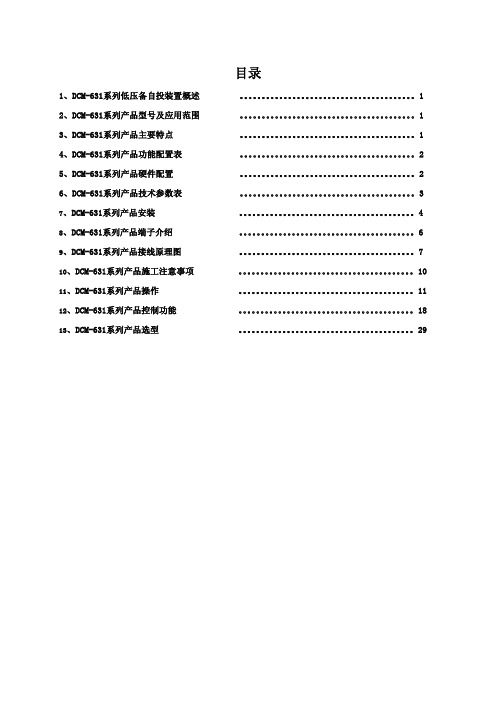
目录1、DCM-631系列低压备自投装置概述 。
12、DCM-631系列产品型号及应用范围 。
13、DCM-631系列产品主要特点 。
14、DCM-631系列产品功能配置表 。
25、DCM-631系列产品硬件配置 。
26、DCM-631系列产品技术参数表 。
37、DCM-631系列产品安装 。
48、DCM-631系列产品端子介绍 。
69、DCM-631系列产品接线原理图 。
710、DCM-631系列产品施工注意事项 。
1011、DCM-631系列产品操作 。
1112、DCM-631系列产品控制功能 。
1813、DCM-631系列产品选型 。
291DCM-631系列低压备自投装置概述DCM-631系列低压备自投装置主要用于690V 以下配电系统,对主备电源进行迅速可靠的切换,确保生产供电的可靠。
具有多种逻辑功能选择,满足不同场合的需求。
并集合三相电量测量/显示、数字输入/输出与网络通讯于一身。
DCM-631低压备自投装置可安装在配电系统内的不同位置。
DCM-631广泛应用在电力系统、工矿企业、公用设施、智能大厦的低压配电系统中,DCM-631具有电力参数测量功能,通过其标准的RS-485通讯接口及双绞线网络与监控系统连接,轻松实现数据的远方管理功能。
DCM-631系列产品型号及应用范围产品型号适用范围DCM-631B:分段备自投装置 两进线开关互为备自 DCM-631Z:主备电源自投自复装置 主备电源互为备用DCM-631M:进线备自投装置 两进线、分段开关相互备用DCM-631F:带发电机备自投装置两进线互为备用,发电机为进线的备用DCM-631系列产品主要特点● DCM-631系列低压备自投装置是针对低压配电系统设计,超小外型尺寸,适用于GCK、GCS、GGD、MNS等各种抽出式(包括1/4抽屉)、固定式及混合式的柜型安装。
具有方便安装、布局合理、维护方便、节约电缆、安全可靠等多种优点;● 全面采用嵌入式SOC (System On Chip 片上系统)设计、32位DSP(Digital Signal Processing 数字信号处理 )技术和冗余现场总线技术,交流采样采用优化全波FFT(Fast Fourier Transform 快速傅立叶变换)技术,软件采用模块化、高抗干扰设计;● 具有多种备自投逻辑功能,充分满足现在电源切换需求;● 装置电源、通讯状态、工况、告警均有LED 指示,方便检测、维护系统; ● 具有多达8路的开入量采集,和最多配置8路开出量的控制;● 可与SIEMENS、SCHNEIDER、GE、AB 等多种品牌的PLC 联网;同时可与KINGVIEW、FIX、WinCC、Intouch 等软件组网;● 配合可拆分式、小型化的中文液晶显示终端,友好的人机界面,可直接监视设备运行状态、运行参数,以及修改保护定值和参数。
- 1、下载文档前请自行甄别文档内容的完整性,平台不提供额外的编辑、内容补充、找答案等附加服务。
- 2、"仅部分预览"的文档,不可在线预览部分如存在完整性等问题,可反馈申请退款(可完整预览的文档不适用该条件!)。
- 3、如文档侵犯您的权益,请联系客服反馈,我们会尽快为您处理(人工客服工作时间:9:00-18:30)。
SGDDGSPin 1On CharacteristicsDynamic CharacteristicsSwitching Characteristics (V GS = -4.5V)Drain-Source Diode CharacteristicsNotes:1. R θJA is the sum of the junction-to-case and case-to-ambient thermal resistance where the case thermal reference is defined as the solder mounting surface of the center drain pad. R θJC is guaranteed by design while R θCA is determined by user’s board design. R θJA = 415 o C/W when mounted on a 1inch 2 copper pad.I DSS Zero Gate Voltage Drain Current V GS = −16V , V GS = 0V ---3µA I GSSGate to Source Leakage CurrentV GS = ±12V , V GS = 0V--±10µAV GS(TH)Gate to Source Threshold VoltageV GS = V DS , I D = -250µA-0.65-0.9-1.5Vr DS(ON)Drain to Source On Resistance I D = -0.5A, V GS = -4.5V - 580 780m ΩI D = -0.4A, V GS = -2.5V- 910 1200C ISSInput CapacitanceV DS = -10V, V GS = 0V,f = 1MHz-85.4-pFC OSSOutput Capacitance - 24.9 - pF C RSSReverse T ransfer Capacitance -8.83-pF Q g(TOT)T otal Gate Charge at -4.5V V GS = 0V to -4.5V V DD = -10VI D = -0.5A I g = 1.0mA- 1.08 1.62nC Q g(-2.5)T otal Gate Charge at -2.5V V GS = 0V to -2.5V-0.67 1.0nC Q gs Gate to Source Gate Charge -0.21-nC Q gdGate to Drain “Miller” Charge-0.33-nCt ON T urn-On Time V DD = -10V , I D = -0.5A V GS = -4.5V, R GS = 120Ω--35ns t d(ON)T urn-On Delay Time -10-ns t r Rise Time-13-ns t d(OFF)T urn-Off Delay Time -40-ns t f Fall Time -24-ns t OFFT urn-Off Time--96nsV SD Source to Drain Diode Voltage I SD = -0.5A--0.9-1.2V t rr Reverse Recovery Time I SD = -0.5A, dI SD /dt = 100A/µs --22ns Q RRReverse Recovered ChargeI SD = -0.5A, dI SD /dt = 100A/µs--16nCFigure 1. Normalized Power Dissipation vsAmbient TemperatureFigure 2. Maximum Continuous Drain Current vsCase TemperatureFigure 3. Normalized Maximum Transient Thermal ImpedanceFigure 4. Peak Current CapabilityT A , AMBIENT TEMPERATURE (oC)P O W E R D I S S I P A T I O N M U L T I P L I 02550751001500.20.40.60.81250.20.4255075100125150-I D , D R A I N C U R R E N T (A T A , CASE TEMPERATURE (oC)V GS = -4.5VV GS = -2.5V0.010.1110-410-310-210-1100101102103210-5t, RECTANGULAR PULSE DURA TION (s)Z θJ A , N O R M A L I Z E DT H E R M A L I M P E D A N C ENOTES:DUTY FACTOR: D = t1/t2PEAK T J = P DM x Z θJA x R θJA + T AP DMt 1t 20.50.20.10.050.010.02DUTY CYCLE - DESCENDING ORDER 1100.42010-510-410-310-210-1100101102103-I D M , P E A K C U R R E N T (A )t, PULSE WIDTH (s)TRANSCONDUCTANCE MAY LIMIT CURRENT IN THIS REGIONV GS = -2.5VT A = 25o CI = I 25150 - T A 125FOR TEMPERATURESABOVE 25o C DERA TE PEAK CURRENT AS FOLLOWS:V GS = -4.5VFigure 5.Forward Bias Safe Operating AreaFigure 6. Transfer CharacteristicsFigure 7. Saturation CharacteristicsFigure 8. Drain to Source On Resistance vs GateVoltage and Drain CurrentFigure 9. Normalized Drain to Source On Resistance vs Junction Temperature Figure 10. Normalized Gate Threshold Voltage vsJunction Temperature0.111100.0530V DS , DRAIN TO SOURCE VOLTAGE (V)-I D , D R A I N C U R R E N T T J = MAX RA TED T A = 25o CSINGLE PULSE LIMITED BY r DS(ON)AREA MA Y BE OPERATION IN THIS100µs10ms1ms121234-I D , D R A I N C U R R E N T -V GS , GATE TO SOURCE VOLTAGE (V)T J = 150o CT J = 25o CT J = -55o C1230.51.01.52.02.53.0-I D , D R A I N C U R R E N T (A )-V DS , DRAIN TO SOURCE VOLTAGE (V)V GS = -2.5VPULSE DURATION = 80µs DUTY CYCLE = 0.5% MAXV GS = -2VT A = 25o CV GS = -4.5V0.50.60.70.80.91.023456I D = -0.1A-V GS , GATE TO SOURCE VOLTAGE (V)I D = -0.5Ar D S (O N ), D R A I N T O S O U R C E O N R E S I S T A N C E (Ω)PULSE DURATION = 80µs DUTY CYCLE = 0.5% MAX0.751.001.251.50-80-404080120160N O R M A L I Z E D D R A I N T O S O U R C E T J , JUNCTION TEMPERATURE (oC)O N R E S I S T A N C EV GS = -4.5V, I D = -0.5APULSE DURATION = 80µs DUTY CYCLE = 0.5% MAX0.60.81.01.2-80-404080120160N O R M A L I Z E D G A T E T J , JUNCTION TEMPERATURE (oC)V GS = V DS , I D = 250µAT H R E S H O L D V O L T A G EFigure 11. Normalized Drain to Source Breakdown Voltage vs Junction TemperatureFigure 12. Capacitance vs Drain to SourceVoltageFigure 13. Gate Charge Waveforms for Constant Gate Currents0.951.001.05-80-404080120160T J , JUNCTION TEMPERA TURE (o C)N O R M A L I Z E D D R A I N T O S B R E A K D O W N V O L T A 100.1110520C , C A P A C I T A N C E (p F -V DS , DRAIN TO SOURCE VOLTAGE (V)V GS = 0V, f = 1MHzC OSS ≅ C DS + C GDC RSS = C GD24681000.51.01.52.0-V G S , G A T E T O S O U R C E V O L T A G E (V )Qg, GATE CHARGE (nC)V DD = -10VI D = -0.5A I D = -0.1AWAVEFORMS INDESCENDING ORDER:DBREAK 7 11 DBREAKMOD DPLCAP 10 6 DPLCAPMOD EBREAK 5 11 17 18 -23.3EDS 14 8 5 8 1EGS 13 8 6 8 1ESG 5 10 8 6 1EVTHRES 6 21 19 8 1EVTEMP 6 20 18 22 1IT 8 17 1LDRAIN 2 5 1e-9LGATE 1 9 0.47e-9LSOURCE 3 7 0.47e-9MMED 16 6 8 8 MMEDMOD MSTRO 16 6 8 8 MSTROMOD MWEAK 16 21 8 8 MWEAKMOD RBREAK 17 18 RBREAKMOD 1RDRAIN 50 16 RDRAINMOD 280e-3RGATE 9 20 12.4RLDRAIN 2 5 10RLGATE 1 9 4.7RLSOURCE 3 7 4.7RSLC1 5 51 RSLCMOD 1e-6RSLC2 5 50 1e3RSOURCE 8 7 RSOURCEMOD 190e-3RVTHRES 22 8 RVTHRESMOD 1RVTEMP 18 19 RVTEMPMOD 1S1A 6 12 13 8 S1AMOD S1B 13 12 13 8 S1BMOD S2A 6 15 14 13 S2AMOD S2B 13 15 14 13 S2BMOD VBAT 22 19 DC 1ESLC 51 50 VALUE={(V(5,51)/ABS(V(5,51)))*(PWR(V(5,51)/(1e-6*20),2.5))}.MODEL DBODYMOD D (IS = 7.7e-11 N=1.277RS = 1e-3TRS1 = 2.8e-1TRS2 = 3e-4 XTI=0 IKF=0.5CJO = 3.9e-11TT=33e-9 M = 0.50).MODEL DBREAKMOD D (RS = 5.3e-1TRS1 = 5.5e-3TRS2 = -9e-5).MODEL DPLCAPMOD D (CJO = 0.5e-10IS = 1e-30N = 10 M = 0.55).MODEL MMEDMOD PMOS (VTO = -1.17 KP = 0.6 IS=1e-30 N = 10 TOX = 1 L = 1u W = 1u RG = 12.4).MODEL MSTROMOD PMOS (VTO = -1.45 KP = 1.5 IS = 1e-30 N = 10 TOX = 1 L = 1u W = 1u).MODEL MWEAKMOD PMOS (VTO = -0.99 KP = 0.05 IS = 1e-30 N = 10 TOX = 1 L = 1u W = 1u RG = 124 RS = 0.1).MODEL RBREAKMOD RES (TC1 = 5.5e-4TC2 = -1e-7).MODEL RDRAINMOD RES (TC1 = 2.8e-3TC2 = 4.9e-6).MODEL RSLCMOD RES (TC1 = 3.7e-3 TC2 = 7.8e-6).MODEL RSOURCEMOD RES (TC1 = 3e-3 TC2 = 5.2e-6).MODEL RVTHRESMOD RES (TC1 = 9e-4 TC2 = 3e-7).MODEL RVTEMPMOD RES (TC1 = -5.5e-4TC2 = -1e-9).MODEL S1AMOD VSWITCH (RON = 1e-5ROFF = 0.1VON = 0.5VOFF= 0.2).MODEL S1BMOD VSWITCH (RON = 1e-5ROFF = 0.1VON = 0.2VOFF= 0.5).MODEL S2AMOD VSWITCH (RON = 1e-5ROFF = 0.1VON = 0.4VOFF= -0.1).MODEL S2BMOD VSWITCH (RON = 1e-5ROFF = 0.1VON = -0.1VOFF= 0.4).ENDSNote: For further discussion of the PSPICE model, consult A New PSPICE Sub-Circuit for the Power MOSFET Featuring Global Temperature Options ; IEEE Power Electronics Specialist Conference Records, 1991, written by William J. Hepp and C. Frank Wheatley.1GATE RGA TE EVTEMP18229+1213814131315S1A S1B S2AS2BCACBEGSEDS CINMWEAKRDRAINDBREAKEBREAKDBODYRSOURCESOURCERBREAK RVTEMPVBATITEVTHRES DPLCAPESLC RSLC1RSLC265150551162111814586873171819++++++19822MMEDMSTRO RVTHRESLSOURCERLSOURCERLDRAINLGA TERLGA TE2081718dp..model dbreakmod = (rs = 5.3e-1, trs1 = 5.5e-3, trs2 = -9.0e-5)dp..model dplcapmod = (cjo = 0.5e-10, isl=10e-30, nl=10, m=0.55)m..model mmedmod = (type=_p, vto = -1.17, kp=0.6, is=1e-30, tox=1)m..model mstrongmod = (type=_p, vto = -1.45, kp = 1.5, is = 1e-30, tox = 1)m..model mweakmod = (type=_p, vto = -0.99, kp = 0.05, is = 1e-30, tox = 1, rs=0.1)sw_vcsp..model s1amod = (ron = 1e-5, roff = 0.1, von = 0.5, voff = 0.2)sw_vcsp..model s1bmod = (ron = 1e-5, roff = 0.1, von = 0.2, voff = 0.5)sw_vcsp..model s2amod = (ron = 1e-5, roff = 0.1, von = 0.4, voff = -0.1)sw_vcsp..model s2bmod = (ron = 1e-5, roff = 0.1, von = -0.1, voff = 0.4)c.ca n12 n8 = 0.6e-10c.cb n15 n14 = 1.1e-10c.cin n6 n8 = 0.75e-10dp.dbody n5 n7 = model=dbodymod dp.dbreak n7 n11 = model=dbreakmod dp.dplcap n10 n6 = model=dplcapmod i.it n8 n17 = 1l.ldrain n2 n5 = 1e-9l.lgate n1 n9 = 0.47e-9l.lsource n3 n7 = 0.47e-9m.mmed n16 n6 n8 n8 = model=mmedmod, l=1u, w=1u m.mstrong n16 n6 n8 n8 = model=mstrongmod, l=1u, w=1u m.mweak n16 n21 n8 n8 = model=mweakmod, l=1u, w=1ures.rbreak n17 n18 = 1, tc1 = 5.5e-4, tc2 = -1e-7res.rdrain n50 n16 = 280e-3, tc1 = 2.8e-3, tc2 = 4.9e-6res.rgate n9 n20 = 12.4res.rldrain n2 n5 = 10res.rlgate n1 n9 = 4.7res.rlsource n3 n7 = 4.7res.rslc1 n5 n51= 1e-6, tc1 = 3.7e-3, tc2 =7.8e-6res.rslc2 n5 n50 = 1e3res.rsource n8 n7 = 190e-3, tc1 = 3e-3, tc2 =5.2e-6res.rvtemp n18 n19 = 1, tc1 = -5.5e-4, tc2 = -1e-9res.rvthres n22 n8 = 1, tc1 = 9e-4, tc2 = 3e-7spe.ebreak n5 n11 n17 n18 = -23.3spe.eds n14 n8 n5 n8 = 1spe.egs n13 n8 n6 n8 = 1spe.esg n5 n10 n6 n8 = 1spe.evtemp n20 n6 n18 n22 = 1spe.evthres n6 n21 n19 n8 = 1sw_vcsp.s1a n6 n12 n13 n8 = model=s1amod sw_vcsp.s1b n13 n12 n13 n8 = model=s1bmod sw_vcsp.s2a n6 n15 n14 n13 = model=s2amod sw_vcsp.s2b n13 n15 n14 n13 = model=s2bmod v.vbat n22 n19 = dc=1equations {i (n51->n50) +=iscliscl: v(n51,n50) = ((v(n5,n51)/(1e-9+abs(v(n5,n51))))*((abs(v(n5,n51)*1e6/20))** 2.5))}}1GA TE RGA TE EVTEMP18229+1213814131315S1A S1B S2A S2BCA CB EGSEDS CINMWEAKRDRAINDBREAKEBREAKDBODYDRAIN RSOURCESOURCERBREAK RVTEMPVBATITEVTHRES ESGDPLCAPISCL RSLC1RSLC268610551501621118145868731718192++++++19822MMEDMSTRORVTHRESLSOURCERLSOURCELDRAINRLDRAINLGATERLGATE2081718CTHERM3 c3 c4 5.5e-4CTHERM4 c4 c5 1.4e-3CTHERM5 c5 c6 2.2e-3CTHERM6 c6 c7 2.6e-3CTHERM7 c7 c8 6.6e-3CTHERM8 c8 Ambient 0.29 RTHERM1 Junction c2 11.2 RTHERM2 c2 c3 11.5RTHERM3 c3 c4 12.5RTHERM4 c4 c5 27RTHERM5 c5 c6 81RTHERM6 c6 c7 88RTHERM7 c7 c8 92RTHERM8 c8 Ambient 93 SABER Thermal Model SABER thermal model FDG6318PZ Copper Area= 1sq.intemplate thermal_model th tlthermal_c th, tl{ctherm.ctherm1 th c2 = 0.17e-4ctherm.ctherm2 c2 c3 = 2.7e-4 ctherm.ctherm3 c3 c4 = 5.5e-4 ctherm.ctherm4 c4 c5 = 1.4e-3 ctherm.ctherm5 c5 c6 = 2.2e-3 ctherm.ctherm6 c6 c7 = 2.6e-3 ctherm.ctherm7 c7 c8 = 6.6e-3 ctherm.ctherm8 c8 tl = 0.29 rtherm.rtherm1 th c2 = 11.2 rtherm.rtherm2 c2 c3 = 11.5 rtherm.rtherm3 c3 c4 = 12.5 rtherm.rtherm4 c4 c5 = 27 rtherm.rtherm5 c5 c6 = 81 rtherm.rtherm6 c6 c7 = 88 rtherm.rtherm7 c7 c8 = 92 rtherm.rtherm8 c8 tl = 93}RTHERM6RTHERM8RTHERM7RTHERM5RTHERM4RTHERM3CTHERM4CTHERM6CTHERM5CTHERM3CTHERM2CTHERM1tl234567AMBIENT8RTHERM2RTHERM1CTHERM7CTHERM8TRADEMARKSThe following are registered and unregistered trademarks Fairchild Semiconductor owns or is authorized to use and is not intended to be an exhaustive list of all such trademarks.DISCLAIMERFAIRCHILD SEMICONDUCTOR RESERVES THE RIGHT TO MAKE CHANGES WITHOUT FURTHER NOTICE TO ANY PRODUCTS HEREIN TO IMPROVE RELIABILITY, FUNCTION OR DESIGN. FAIRCHILD DOES NOT ASSUME ANY LIABILITY ARISING OUT OF THE APPLICATION OR USE OF ANY PRODUCT OR CIRCUIT DESCRIBED HEREIN;NEITHER DOES IT CONVEY ANY LICENSE UNDER ITS PATENT RIGHTS, NOR THE RIGHTS OF OTHERS.LIFE SUPPORT POLICYFAIRCHILD’S PRODUCTS ARE NOT AUTHORIZED FOR USE AS CRITICAL COMPONENTS IN LIFE SUPPORT DEVICES OR SYSTEMS WITHOUT THE EXPRESS WRITTEN APPROVAL OF FAIRCHILD SEMICONDUCTOR CORPORATION.As used herein:1. Life support devices or systems are devices or systems which, (a) are intended for surgical implant into the body,or (b) support or sustain life, or (c) whose failure to perform when properly used in accordance with instructions for use provided in the labeling, can be reasonably expected to result in significant injury to the user.2. A critical component is any component of a life support device or system whose failure to perform can be reasonably expected to cause the failure of the life support device or system, or to affect its safety or effectiveness.PRODUCT STATUS DEFINITIONS Definition of TermsACEx™ActiveArray™Bottomless™CoolFET™CROSSVOLT™DOME™EcoSPARK™E 2CMOS™EnSigna™FACT™FACT Quiet Series™FAST ®FASTr™FRFET™GlobalOptoisolator™GTO™HiSeC™I 2C™ImpliedDisconnect™ISOPLANAR™LittleFET™MicroFET™MicroPak™MICROWIRE™MSX™MSXPro™OCX™OCXPro™OPTOLOGIC ®OPTOPLANAR™PACMAN™POP™Power247™PowerTrench ®QFET™QS™QT Optoelectronics™Quiet Series™RapidConfigure™RapidConnect™SILENT SWITCHER ®SMART START™SPM™Stealth™SuperSOT™-3SuperSOT™-6SuperSOT™-8SyncFET™TinyLogic ®TruTranslation™UHC™UltraFET ®VCX™Across the board. Around the world.™The Power Franchise™Programmable Active Droop™Datasheet Identification Product Status DefinitionAdvance InformationFormative or In Design This datasheet contains the design specifications for product development. Specifications may change in any manner without notice.PreliminaryFirst ProductionThis datasheet contains preliminary data, andsupplementary data will be published at a later date.Fairchild Semiconductor reserves the right to make changes at any time without notice in order to improve design.No Identification Needed Full ProductionThis datasheet contains final specifications. Fairchild Semiconductor reserves the right to make changes at any time without notice in order to improve design.Obsolete Not In ProductionThis datasheet contains specifications on a product that has been discontinued by Fairchild semiconductor.The datasheet is printed for reference information only.。
