基础光学使用说明书(新)
光学仪器操作指南说明书
光学仪器操作指南说明书1. 前言光学仪器是一种高精度的科学工具,它广泛应用于各个领域的研究和实验中。
为了正确而安全地操作光学仪器,本指南将详细介绍光学仪器的操作步骤和注意事项。
请在使用前仔细阅读本指南,并严格按照操作要求进行操作,以确保实验的准确性和安全性。
2. 仪器概述光学仪器是一种用来观测和测量光学现象和参数的工具。
它包括但不限于显微镜、光谱仪、反射折射测量设备等。
每种仪器都有其特定的功能和使用方法,下面将对常见的光学仪器进行操作指南。
2.1 显微镜2.1.1 准备工作在使用显微镜之前,首先确保显微镜放置在水平台面上,并清洁镜头。
使用纯净水或者专门的清洁液擦拭镜头,注意避免划伤镜片。
接下来,启动显微镜并调整光源亮度以获得清晰的观察环境。
2.1.2 操作步骤- 将待观察的样本放置在显微镜的载物台上,并确保样本与镜头垂直对齐。
- 先用低倍镜进行初步观察和调焦,然后再切换到高倍镜进行细节观察。
注意调整焦距以获得清晰的图像。
- 操作时要轻柔移动镜头,避免碰撞和折损。
- 观察完毕后,关闭显微镜,及时清理并保养好仪器。
2.2 光谱仪2.2.1 准备工作将光谱仪放置在水平台面上,并连接电源线和输入输出线。
确保光谱仪与计算机的正常连接。
2.2.2 操作步骤- 启动光谱仪软件,并调整参数以适应实验需求。
- 将待测样品放置在光谱仪的光路上,确保光线正常通过。
- 点击软件上的开始测量按钮,记录数据。
- 根据实验要求进行光谱曲线的分析和处理。
- 实验结束后,关闭软件并及时断开电源线。
清理光谱仪并保养好仪器。
3. 安全注意事项3.1 使用个人防护装备在操作光学仪器时,必须佩戴适当的个人防护装备,如实验室专用眼镜、手套等,以防止意外事故和受伤。
3.2 避免长时间直视强光源光学仪器中常常存在强光源,长时间直视强光会对眼睛造成损伤。
在操作中,应避免用肉眼直接盯着强光源,尽量采取相应的眼部保护措施。
3.3 谨慎操作、轻拿轻放使用光学仪器时要谨慎操作,轻拿轻放。
基础光学(赵凯华版)Chap1 Introduction
1光学2009.02~2009.06教师简介•董建文–2003年理学学士中山大学物理学系光信息–2000-03年辅修中山大学信科学院计算机系–2003-07 光学博士光电材料与技术国家重点实验室–2007年助理研究员香港科技大学物理系•办公室:南校区激光所403•Phone: (020)84111469,84037563-8403•E-email:dongjwen@ •Homepage: /dong/•Course website: http://202.116.84.117:403/2课程提纲(Syllabus )1.引言(Introduction)2.几何光学(Geometrical Optics)3.光的干涉(Interference)4.光的衍射(Diffraction)5.光的偏振(Polarization)6.光的吸收、散射、色散(Absorption,Scattering, Dispersion)7.光的量子现象(Quantum of the light)8.激光(Laser)9.现代光学进展(Progresses of Optics)包括:全息(Holography),光子晶体与负折射率材料(Photonic crystals & Negative refraction metamaterials),量子光学11(Quantum Optics)12参考书(Reference Texts )•《光学》,赵凯华钟锡华,北京大学出版社•《光学》章志鸣等编著,高等教育出版社•《基础光学》,李良德,中山大学出版社•《普通物理学教程——光学》,易明,高等教育出版社•Principles of Optics 7th edition, Born & Wolf, Cambridge•课程要求成绩考核•课堂笔记•平时作业25%•考试成绩20%(Midterm) + 45%(Final)•严肃纪律(点名) 10%•课程网址:http://202.116.84.117:403/第1章引言§1.1 光学发展史1.中国古代它是一门古老的学科。
零基础光学显微镜使用方法
零基础光学显微镜使用方法编撰:杨历佳我在本文中主要介绍的内容有:光学显微镜的组成、各部件的作用和原理、具体的操作方法及注意事项、保养和清洁。
普通光学显微镜按物镜放大倍数可以分10倍、40倍和100倍等。
根据微生物等样本的大小,选择不同的放大倍数。
例如要观察真菌(如酵母菌等)10×10就可以看的很清楚;如果要观察细菌的话至少要用到10×40;想要看的更为清楚就要用100倍的油镜来看,使用油镜时需要滴加香柏油。
一般的镜检用400倍(10×40)基本上就足够了。
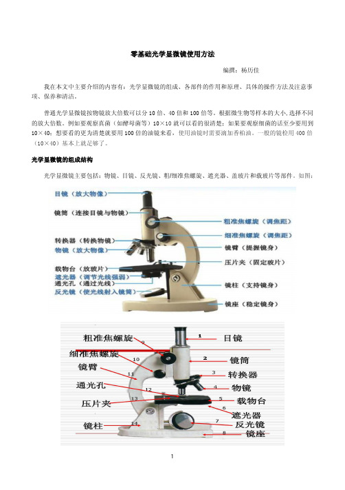
光学显微镜的组成结构光学显微镜主要包括:物镜、目镜、反光镜、粗/细准焦螺旋、遮光器、盖玻片和载玻片等部件。
如图:1、物镜:显微镜的放大作用主要取决于物镜,是显微镜最重要的光学部件,利用光线使被检物体第一次成像。
物镜质量的好坏直接影响显微镜映像质量,它是决定显微镜的分辨率和成像清晰程度的主要部件。
所以对物镜的质量和校正很重要,它是衡量一台显微镜质量的首要标准。
物镜刻有“10×”符号的为低倍镜,刻有“40×”符号的为高倍镜,刻有“100×”符号的为油镜。
以40×物镜为例,物镜上的数字分别为:40/0.65和160(∞)/0.17(1)40表示物镜的放大倍数:放大倍数是指眼睛看到的像的大小与对应标本大小的比值。
它指的是长度的比值而不是面积的比值。
例:放大倍数为100×,指的是长度是1μm的标本,放大后,像的长度是100μm。
要是以面积计算,则放大了10,000倍。
显微镜的总放大倍数等于物镜和目镜放大倍数的乘积;(2)0.65为数值孔径(mm),数值孔径越大,样本观察的分辨率和放大率越大,视场宽度与工作距离越小。
数值孔径的定义是:物镜前透镜与被检物体之间介质的折射率(n)和孔径角(u)半数的正弦之乘积。
(3)160为镜筒长度(mm),∞指无穷大。
机械镜筒长(镜筒长度)是指从物镜的安装定位处到显微镜镜筒上端面的距离,标准定为160mm;(4)0.17为所需盖玻片的标准厚度单位(mm);工作距离(物距):样本调准焦点时,物镜前端与试样或盖玻片顶面的距离。
特里多尼克基础照明控制与连接性产品说明书

Product description• Compact dimensions for luminaire installation• For up to 20 DSI or DALI devices (max. 10 per output channel)• DALI IN input• 2 DALI/DSI output channels with adjustable offset from channel 2 to channel 1• 1 relais output• Sensor input for up to 4 basicDIM DGC sensors 5DPI 14• 2 switch inputs for on/off switching and dimming• Individual adjustment of the parameters withbasicDIM DGC Programmer orsoftware masterCONFIGURATOR• 5 years guarantee (conditions at )ÈWiring diagrams and installation examples, page 10basicDIM DGC Compact control moduleTechnical dataRated supply voltage220 – 240 V Mains frequency50 / 60 Hz Power 2.5 WStand-by power0.5 WCurrent draw, input (DALI bus) 2 mAMax. number of switched drivers2Max. Inrush current of the load (peak / duration)55 A / 400μs Typ. number of switching cycles150,000Max. resistive load500 WMax. inductive / capacitive load200 VA Dimming range 1 – 100 %tc70 °C Operating temperature0 ... +60 °C Storage temperature-25 ... +70 °C Type of protection IP20 Dimensions L x W x H159 x 30 x 21 mm basicDIM DGCCompact control moduleOrdering dataType Article number Mounting Packaging carton Weight per pc. basicDIM DGC28000920Luminaire installation10 pc(s).0.06 kgSpecific technical dataType Inputs Outputs CH2 as Link LineDimming switch Max. cable length at1.5 mm²Max. basicDIMDGC sensorsMax. sensor linelength at 0.2 –1.5 mm²Digital controlline DALI/DSIControl output per physicaloutput (devices)Maximum cablelength at 1.5mm²Voltage DC Maximum cablelength at 1.5mm²Number ofcombinablemodulesbasicDIM DGC double100 m410 m210100 m13 V100 m10 1 See data sheet 8.2 Switching cycles.Product description• Light measurement and motion detection• Up to 4 basicDIM DGC sensors on one basicDIM DGC• Can be remote controlled• Light measurement and motion detection can be deactivated • Individual adjustment of the parameters with basicDIM DGC Programmer or software masterCONFIGURATOR• Power supply via basicDIM DGCTechnical dataØ of detection range, mounted at a height of 2.5 m 4.5 mSwivel design noDetection angle84°Light measurement at the sensor head 110 – 650 lxInfra-red control range 5 mMax. mounting height 5 mOperating temperature0 ... +50 °CStorage temperature-25 ... +55 °CType of protection IP20basicDIM DGC Sensor 5DPI 14f44,4Ø13,916,41,9312,8219,7Ordering dataType Article numberPackaging,Weight per pc.1The measured value at the sensor head corresponds to approx. 15 to 2,000 lux on the surface measured.Product description• Mounting frame for attaching all 5DP 14f sensor directly to the luminaire housing• Shutter for preventing movement detection in one direction•Glow wire test with 750 °C according to EN 61347-15DPI 14f Mounting KitOrdering dataProduct description• Mounting frame for wired 5DP 14f sensors allowing direct mounting to the ceiling• Easy …click in“ installation of the sensor• IP20• Casing: plastic, white• UV stabilized plastic• DALI MSensor 5DPI 14 is powered via DALI circuit, basicDIM DGC Sensor 5DPI 14f powered via control unit• Optional shutter for reduction of movement detection area allowing to decrease the movement detection area from 360° to 240°• Mounting kit with screws and decorative plugs• 0.5 mm wiring for the sensor• Two 3 x 1.5 mm² clamps with cable management (2 entry points on oppsite sides)• Glow wire test with 750 °C according to EN 61347-1ACU Sensor Housing 14rs IP20Ordering databasicDIM DGC Sensor 5DPI 14rc65,45,5Ø46,75Ø58128Ordering dataTypeArticle number Packaging, Weight per pc.Product description• Light measurement and motion detection• Up to 4 basicDIM DGC sensors on one basicDIM DGC • Can be remote controlled• Light measurement and motion detection can be deactivated • Individual adjustment of the parameters with basicDIM DGC Programmer or software masterCONFIGURATOR • Power supply via basicDIM DGC Technical dataØ of detection range, mounted at a height of 2.5 m 4.5 m Swivel design no Detection angle84°Light measurement at the sensor head 110 – 650 lx Infra-red control range 5 m Max. mounting height 5 m Operating temperature 0 ... +50 °CStorage temperature -25 ... +55 °C Type of protectionIP201The measured value at the sensor head corresponds to approx. 15 to 2,000 lux on thesurface measured.Product description• Optional infra-red programming unit for basicDIM DGC • Setting of predefined discrete parameter values • Programmable functions such as light level, time delay,P.I.R., bright-out, power upbasicDIM DGC ProgrammerOrdering dataREMOTECONTROL IR6A C C E S -S O R I E SOrdering dataProduct description• Optional infra-red remote control • Switching on and off (On/Off button)• Dimming (Up/Down button)• Activation of automatic lighting control •Setting the threshold control point (Set button)Strain-relief setOrdering dataProduct description• Strain relief for up to 3 cables suitable for cable with diameter from 2.5 up to 9 mm • A: 2.5 – 5 mm diameter • B: 5 – 9 mm diameter • C: 5 – 9 mm diameter• Optional strain-relief set for independent applications • Transforms the unit into a full Class II compatible unit (e.g. for ceiling installation)• One set includes 2 pieces strain-reliefs • 5 years guarantee1. StandardsEN 55015EN 61000-3-2EN 61347-1EN 61347-2-11EN 61547EN 62386-101EN 60598-11.1 DALI standardThe basicDIM DGC is designed to control control gear with DALI standardIEC 60929 (DALI V0) and IEC 62386 (DALI V1).1.2 Glow-wire testaccording to EN 61347-1 passed.2. CommonThe basic DIM DGC provides the basis for an easy-to-use and cost-effective lighting system with motion detection.When the sensor detects movement it triggers a individual adjustable motion detection profile in the control unit.As the amount of natural ambient light changes the illuminance from the artificial lighting system is adjusted.The connected luminaires can be switched on and off via momentary-action switch or remote control possible.The DALI IN interface allows integration of the basicDIM DGC module also into a comfortDIM system.The basicDIM DGC module has 5 preprogrammed profiles which can be selected using the basicDIM DGC Programmer.The profiles can be adjusted to your application via the masterCONFIGURATOR (≥ V2.12) software.If the basicDIM DGC module is used in the basic application, the CH2 can be used as control channel for controlling subordinate basicDIM DGC modules (basic connection), so that the controlling and the subordinate basicDIM DGC modules can be programmed and allocated to groups using the masterCONFIGURATOR software. Every single basicDIM DGC module can be allocated to a group and respond to the presence of up to 5 groups (for more detailed information please refer to the masterCONFIGURATOR documentation).3. Interfaces / communication3.1 DALI INThe DALI IN interface allows integration of the basicDIM DGC module alsointo a comfortDIM or other BMS systems.However, not all DALI commands are supported. The DALI commandssupported are listed in the operating instructions.By using the DGC in basic configuration (additional DGC‘sconnected to CH2) DALI IN interface will be deactivated.3.2 DALI/DSI output channels CH1 - CH2The output channels can be set to DSI or DALI (default) using the basicDIMDGC Programmer or the masterCONFIGURATOR software.After mains failure the basicDIM DGC will set new the followingparameters to CH1/CH2:POWER ON LEVELSYSTEM FAILURE LEVELFADE TIMEMIN LEVELMAX LEVELFor more detailed information please refer to the manual.4. Installation• basicDIM DGC can be operated without sensor.The motion detection must be disabled via masterCONFIGURATOR or with unique connecting a sensor and basicDIM DGC Programmer.• DSI/DALI is not SELV. The installation instructions for mains voltage therefore apply.• The maximum cable length between the external switch and basicDIM DGC is 100 m.• The maximum cable length between the sensor and basicDIM DGC is 10 m.• A synchronous operation of DALI and DSI ballasts at the same control gear is not possible.• The output channels (for a cable cross-section of 1.5 mm2) must not be exceeded 100 m.• If CH2 is used as link line, the maximum cable length must not exceed 100 m (at 1.5 mm²).• If a basicDIM DGC is connected to CH2, DALI IN is disabled and CH2 is used as Link-Line (neighbourhood function).No control commands are transmitted via CH2, to reactivate DALI IN see basicDIM DGC manual.• Any number of push to make switches may be connected in parallel to the inputs.• Do not connect standard switches to the input.• Please ensure that the detection range of the sensor lies in the lighting area of the controlled luminaires.• Heaters, fans, printers and copiers located in the detection zone may cause incorrect presence detection.• To avoid false readings, the sensor should be installed so there is no direct light from the lamp in the detection zone.• Sensor wires must be routed separately from the lamp wires andmains cables otherwise the lighting control system may malfunction.If separate routing is not possible (for reasons of space) shieldedlamp wires and mains cables must be used.• Avoid direct illumination of the light source on the sensor includinghousing.3.3 SwitchbasicDIM DGC has two inputs (T1 and T2) for two external switches. Any number of switches can be connected in parallel to the inputs(parallel connection of T1 and T2 possible).Short press (< 500 ms):ON/OFFLong press (> 500 ms):Dim up/downA change in the light value deactivates lighting regulation only temporarily. As soon as the luminaire has beenautomatically switched on again (motion detection) or manually switched off and on again, regulation isactivated again.2 x short press:The overwritten setpoint light value is stored (luminaire acknowledges by flashing twice)Function is lockable via the DSI programmerDifferent output channels are controlled, depending on the profile selected.4.1 Wiring diagram basicDIM DGC DALIN L DA DA* must be the same phase as for LRelais in standbyN L L’DA DAmax. 64 DGC* must be the same phase as for LWiring diagram basicDIM DGC for Inteligent LuminaireNL DA DAmax. 64 DGCNL4.2 Wiring diagram basicDIM DGC with DALI PS1(2)Use only in combination with DALI Repeater (86458401) and one of the following DALI supplies:DALI PS1 (24034323), 200 mA, max. 100 additional devices DALI PS2 (28000876), 240 mA, max. 120 additional devices This combination can be used on CH1 and CH2.SensorD1D2D1D2D1D2C0C1B0B1A1A24.3 Wiring and mounting ACU Sensor Housing 14rs IP20wire preparation:4.4 Wiring type and cross-sections for basicDIM DGC For wiring use solid wire from 0.5 to 1.5 mm².wire preparation:4.5 Wiring type and cross section for sensor rc versionFor wiring use stranded wire with ferrules or solid wire from 0.2 to 1.5 mm².���� – ��� mm² solid or 4.6 Wiring type and cross section for sensor f versionFor wiring use stranded wire with ferrules from 0.2 to 0.5 mm² or solid wire from 0.14 to 0.5 mm².4.7 Mounting variants luminaire installation sensor Size of the sheet: 0.8 – 1.8 mmø14,1+0,21,5 – 2,5Size of the sheet: 0.8 – 3.0 mmSize of the sheet: 0.6 – 0.8 mm3,2 0 -0,15ø1,8 +0,1 020 +0,1 -0,14+0,2 02,2+0,219,1-0,24.8 Mounting in luminaire housing with Mounting Kit:Size of the sheet: 0.8 – 2.0 mmDimension drawing for neededmounting opening4.9 Mounting Kit mounting4.10 Mounting Kit Shutter Area which is masked by the shutter.4.11 Mounting in class II luminaireThe Sensor provides basic insulation as required by IEC 62386-101 and defined in IEC 61347-1.If the sensor is built into a class II luminaire which has to provide double or reinforced insulation it has to be considered that the Sensor is not a class II device. Still the Sensor can be used for such projects as the front of the sensor is tested to fulfill the class II requirements for double or reinforced insulation.Class II5. basicDIM DGC sensor functions5.2 Presence / motion detection5.1 Light level recognition area* The recommended maximum room height for officeapplications is 3 m and for corridor applications for example 4 m. Up to 2 m mounting height presence is detected andover 2 m motion is detected.Calculation of the diameter (light area):x1 = tan(a x1) × h x2 = tan(a x2) × h y = tan(a y ) × hCalculation of the diameter (motion area):d = 2 × tan(0,5 × a ) × hh *x1x2y d 1.7 m1.3 m 0.7 m 1.0 m 3.0 m2.0 m 1.6 m 0.8 m 1.2 m3.6 m 2.3 m 1.8 m 0.9 m 1.3 m4.1 m 2.5 m 2.0 m 1.0 m 1.4 m 4.5 m 2.7 m 2.1 m 1.1 m 1.6 m 4.9 m 3.0 m 2.3 m 1.2 m 1.7 m5.4 m 3.5 m 2.7 m 1.4 m 2.0 m6.3 m 4.0 m3.1 m1.6 m2.3 m7.2 mExample for light and motion detection area at height of 1.7 m:6. Functions6.1 RelaisThe relay can be used in four different operating modes:• Reduction of standby losses (standby wiring example)• Independent output channel for switching non-dimmable luminaires (DALI wiring example)Depending on the profile used, the relay will respond differently. For the 5 main profiles, the two relay profiles used are Standby and OnlyOFF. The masterCONFIGURATOR software allows to enable or disable the relay profiles as well.Depending on the profile used, different operating modes arepreprogrammed for the presence detector. These can be changed using thebasicDIM DGC Programmer or the masterCONFIGURATOR software.6.2 Run-on timeRun-on time of the presence detector, run-on time starts when no presence is detected.The run-on time may vary depending on the profile used.You can choose whether you want the basicDIM DGC module to switch off the light completely or to dim it down to the absence value after the run-on time.It can also be changed using the basicDIM DGC Programmer or the masterCONFIGURATOR software.Absence valueSwitch-off delayThe absence value (light level) and the switch-off delay (the period for which the level is maintained) differ depending on the profile used; theseparameters may be changed using the basicDIM DGC Programmer or themasterCONFIGURATOR software.6.3 OffsetDepending on the profile used, a negative offset may be enabled between CH2 and CH1. Using the basicDIM DGC Programmer and themasterCONFIGURATOR software, this parameter may be changed (also positive offset possible).6.4 Manual-off delayIf the light is switched off manually via momentary-action switch or remote control, the presence detector is disabled. After a period of delay without any presence detected, the presence detector is enabled again. If the sensor detects presence during the “Manual Off” delay, the delay time will start all over again. It can only be changed by using the masterCONFIGURATOR software.6.5 Lighting controlLighting control is started via the Auto key of the basicDIM Programmer or REMOTECONTROL IR6.If the basicDIM DGC module has been switched on via the ON key, lighting control is disabled.If you want to use lighting control, you need to start the DGC module via the Auto key.Lighting control can also be disabled using the masterCONFIGURATOR software.6.6 Set target valueThe light level can be set via following options: • REMOTECONTROL IR6 (press the key for > 3 s)• basicDIM DGC Programmer (press the key for > 3 s)•masterCONFIGURATOR software • external momentary-action switch: By briefly pressing the momentary-action switch twice the currently measured light level is saved as new target value.(Depending on the profile used, this function is enabled or disabled, but it can be changed using the basicDIM DGC Programmer or the masterCONFIGURATOR software)6.7 Bright-outIf the nominal illuminance level (e.g. 500 lx) is exceeded for 10 minutes at over 150 % (e.g. 750 lx), the light is switched off, even if presence is detected.The light is switched on again as soon as the measured light level falls below the target value.Depending on the profile used, this function is either enabled or disabled and can be changed using the basicDIM DGC Programmer orthe masterCONFIGURATOR software.The bright-out status can be indicated on the sensor by a slowly flashing green status LED.By default this function is disabled, but it can be enabled using the masterCONFIGURATOR software.Light control incl. bright-out activated for CH1. CH2 is not illuminated controlled.6.8 Neighbourhood functionDepending on the profile used, the basicDIM DGC can respond to presence detected in other groups.These functions can be changed using the basicDIM DGC Programmer or the masterCONFIGURATOR software.6.9 Momentary-action switch inputs6.10 Basic functions 6.12 Behaviour after return of powerThe basicDIM DGC module features two different types of starting behaviourafter mains failure.6.11 ProfilesProfile 1: Individual room Profile 2: Classroom Profile 3: Corridor Profile 4: WCProfile 5: Free-standing luminaire (default profile)Profile Test:You may use the Profile Test to check the profile you selected.All times relevant to the profile are reduced to 15 s.The Profile Test will automatically be terminated after 1 h, or by pressing the Auto key of the basicDIM DGC Programmer.The profiles can be adjusted to your needs via the masterCONFIGURATOR software or the DGC Programmer.For more detailed information please refer to the masterCONFIGURATOR documentation at .7. Brief description of profiles7.1 Individual room profile7.2 Classroom profile7.3 Corridor profile7.4 WC profile7.5 Free-standing luminaire profile (default)8. Miscellaneous8.1 DisposalAccording to the WEEE directive return old equipment at appropriate collection facilities.8.2 Additional informationAdditional technical information at → Technical Data Guarantee conditions at → ServicesLifetime declarations are informative and represent no warranty claim.No warranty if device was opened.8.3 Switching cyclesThe number of switching cycles is directly related to the level and duration of the inrush current. To increase the number of cycles either LED drivers with lower inrush current (e.g. Tridonic Industry LED drivers) oran additional external relay can be used.。
XGS-2型信息光学及基础实验使用说明书
目录实验一用自准法测薄凸透镜焦距f (2)实验二用位移法测薄凸透镜焦距f (3)实验三目镜焦距f e的测量 (5)实验四自组显微镜 (6)实验五自组望远镜 (8)实验六自组透射式幻灯机(投影系统) (10)实验七测节点位置及透镜组焦距 (11)实验八自组加双波罗棱镜的正像望远镜 (15)实验九杨氏双缝干涉 (16)实验十菲涅尔双棱镜干涉 (19)实验十一菲涅尔双面反射镜干涉 (22)实验十二洛埃镜干涉 (25)实验十三牛顿环装置 (27)实验十四夫郎和费单缝衍射 (29)实验十五夫郎和费圆孔衍射 (32)实验十六菲涅尔单缝衍射 (33)实验十七菲涅尔圆孔衍射 (34)实验十八菲涅尔直边衍射 (36)实验十九偏振光分析 (38)实验二十全息照相 (44)实验二十一制作全息光栅 (49)实验二十二阿贝成像原理和空间滤波 (52)实验二十三θ调制和颜色合成 (55)实验一用自准法测薄凸透镜焦距f (测量实验)一、实验目的⑴掌握简单光路的分析和调整方法⑵了解、掌握自准法测凸透镜焦距的原理及方法二、实验原理当发光点(物)处在凸透镜的焦平面时,它发出的光线通过透镜后将成为一束平行光。
若用与主光轴垂直的平面镜将此平行光反射回去,反射光再次通过透镜后仍会聚于透镜的焦平面上,其会聚点将在发光点相对于光轴的对称位置上。
三、实验仪器1、带有毛玻璃的白炽灯光源S2、品字形物象屏P:SZ-143、凸透镜L:f=190mm(f=150mm)4、二维调整架:SZ-075、平面反射镜M6、二维调整架:SZ-077、通用底座:SZ-048、二维底座:SZ-029、通用底座:SZ-0410、通用底座:SZ-04四、仪器实物图及原理图五、实验步骤1、把全部元件按图一的顺序摆放在平台上,靠拢,调至共轴。
而后拉开一定的距离。
可调成如图一所示的距离2、前后移动凸透镜L ,使在物像屏P 上成一清晰的品字形像。
3、调M 的倾角,使P 屏上的像与物重合。
2024年度ZEMAX中文使用说明书pdf

设计流程与关键步骤
明确设计目标
确定光学系统的性能指标,如焦距、视场角 、分辨率等。
选择合适的光学元件
根据设计目标,选择适当的透镜、反射镜等光 学元件。
建立光学模型
利用ZEMAX等光学设计软件,建立光学系统的数 学模型。
2024/3/23
优化设计
通过调整光学元件的参数,优化光学系统的性能, 使其达到设计目标。
29
06 ZEMAX高级功能 与应用拓展
2024/3/23
30
非序列模式设计技巧
1 2 3
灵活设置光源和探测器
在非序列模式中,用户可以自由定义光源和探测 器的位置、方向和属性,以模拟实际光学系统中 的复杂光线传播。
使用非序列元件
ZEMAX提供了丰富的非序列元件库,如反射镜 、透镜、棱镜等,用户可以根据需要选择合适的 元件进行建模。
3
软件背景及发展历程
创立初期
ZEMAX软件最初是由美国Focus Software Inc.公司开发,专注于 光学设计领域。
发展壮大
随着光学行业的快速发展, ZEMAX软件不断更新迭代,逐渐 成为光学设计领域的标准工具。
收购与整合
2018年,ZEMAX被美国Radiant Vision Systems公司收购,进一 步整合资源,拓展应用领域。
偏振光优化
ZEMAX的优化算法同样适用于偏振光系统 ,可以对系统进行优化以提高偏振性能。
32
激光束传播模拟技术
激光束建模
ZEMAX支持激光束的建模和分析,用户可以定义激光束 的波长、功率、光束质量等参数。
01
激光束追迹
通过激光束追迹功能,可以模拟激光束 在光学系统中的传播过程,并分析光束 形状、功率分布等特性。
实验30 基础光学综合设计实验系统说明书

基础光学综合实验系统实验说明书北京方式科技有限责任公司基础光学综合实验系统基础光学综合设计实验系统是以专用光学实验平台为实验操作面,配置大量光学、机械附件和器件,通过灵活搭配和组合;我公司推荐如下几种实验科目,其他拓展实验科目,用户可根据实际需要自行设计。
实验内容及步骤如下一、光的衍射实验1.将所需磁性底座的开关置于开的状态,即可随意移动。
2.将半导体激光器放置于一磁性底座上固定好,同时在平台的左端将磁性底座固定好;将白屏固定于另一磁性底座上,将白屏放置于平台右端,调整半导体激光器,使激光器平行平台表面。
3.将缝元件架紧靠激光器放置,将一维位移架放置在白屏处,并放上12档光探头并锁紧,调节光探头到一维位移架的中间区域。
4.调整激光器指向方位和光探头的高低,使激光准确进入探测光栏孔。
5.在缝元件架上放上缝元件,根据实验内容将要被测的缝或光栅调入光路,在光探头端就会出现一条干涉或衍射图案。
6.旋转探头上的光栏盘使0.2mm缝光栏进入探测位置。
7.转动一维位移架上的丝杠钮,使探头从一端向另一端进行扫描探测,并记录下光探头位置与光功率指示值的对应关系,验证光强分布与波长和缝参数的关系。
二、几何光学实验:1.自准直法测凸透镜焦距:设备:实验平台、白炽灯、品字屏(含毛玻璃)、反射镜、被测凸透镜。
方法:按白光源、品字屏、被测凸透镜、反射镜依次排列。
如下图设备:实验平台、白光源、品字屏(含毛玻璃)、反射镜、f=100mm的凸透镜、被测凹透镜、白屏。
方法:1.将白光源、“品”字屏、凸透镜、白屏依次排列。
2.仔细调整品字屏、f=100mm的凸透镜和白屏之间的距离,使白屏上呈现一个清晰的、略微缩小的倒立的像。
记下像(白屏)在平台上的位置。
要想呈现一个缩小的、倒立的实像,“品”字屏距透镜的距离应是多少?有什么规律?3.取下白屏,在凸透镜后放上被测凹透镜和反射镜。
见下图。
设备:实验平台、白光源、“品”字屏(含毛玻璃)、白屏、被测凸透镜。
GDxPRO 光学仪器操作手册说明书

Frequently Asked Questions for GDxPRO1.What product support is available for GDxPRO™ instruments and for how long?Carl Zeiss Meditec, Inc. guarantees service and product support for GDxPRO instruments for seven years starting from January 1, 2014. For any technical support issues please contact your local ZEISS distributor.2.What are the clinical applications of GDxPRO?GDxPRO technology (Scanning Laser Polarimetry) provides structure analysis of the RNFL (RetinalNerve Fiber Layer) as an aid in the diagnosis of glaucoma.3.What instruments can be used instead of GDxPRO for RNFL structure analysis?OCT technology has become a standard of care for obtaining structure imaging for your patients.We recommend ZEISS CIRRUS™ OCT instruments (CIRRUS HD-OCT or CIRRUS photo) for RNFLstructure analysis. CIRRUS OCT provides more comprehensive structure analysis for glaucomadiagnostics including RNFL, ONH (Optical Nerve Head) and ganglion cell analysis, GPA™ (GuidedProgression Analysis™) and combined structure and function reports.4.Are there any other benefits for transitioning to OCT in addition to the more comprehensive structureanalysis?Additional benefits of using CIRRUS OCT in place of GDxPRO are:∙Efficient workflow, better connectivity, and data management advantages of CIRRUS OCT.∙Association with a fast growing information pool of the OCT clinical data.∙Ability to diagnose wide range of ophthalmic conditions in addition to glaucoma.5.What are my options for acquiring a CIRRUS OCT to replace my GDxPRO?You can explore potential opportunities related to replacing your GDxPRO with CIRRUS OCTinstruments by contacting your local distributor.6.How can the data be transferred from a GDxPRO instrument for archiving?There are several ways of transferring data from the GDxPRO instrument.∙Export a PDF report to a shared folder on the network or attached USB storage device. Reports must be exported individually. This involves manual transfer of data, one scan at a time.∙Export a DICOM ePDF report to a DICOM Storage Provider such as FORUM®. Reports must be exported individually. This involves manual transfer of data, one scan at a time.∙The entire database can be transferred from the GDxPRO instrument to a GDxPRO Review Software installed on a PC.Please consult with your local ZEISS technical support for more details.7.What computer operating systems can be used with the GDxPRO Review software?The GDxPRO Review software was released for Windows XP and Windows Vista 32Bit. GDxPROReview software was not designed for and will not operate on newer Operating Systems such asWindows 7, Windows 8, or similar. Please consult with your local ZEISS technical support forGDxPRO Review System Requirements.8.Can I view my old GDxPRO data sets with CIRRUS Review or any other OCT software?No, OCT and GDxPRO data are not compatible.9.Can I compare my GDxPRO data sets with OCT data?No. Even if the formats of the GDxPRO and CIRRUS reports look similar the data in the reports are different. Neither the numerical results nor the thickness maps or deviation maps should be directly compared. The GDxPRO and OCT technologies are based on different optical properties. GDxPRO uses changes in the polarization properties of light as it traverses the eye to determine thickness at each point and construct an image. OCT uses the interference of light that passes through the tissue of the eye with a reference optical path to determine thickness at each point and construct an image.These two methods do not yield directly comparable results, but there are multiple publications that demonstrate that each method can be used for diagnosis of glaucoma and monitoring ofprogression.10.I have my GDxPRO connected into FORUM. When I switch to OCT could I use all the benefits ofFORUM with OCT as I use with GDxPRO?Yes, and the benefits are much more significant for OCT.For GDxPRO it was possible to transfer only the reports. For OCT you can transfer raw data and analyze data in FORUM. This allows more informative types of analysis and reports, such as structure and function Combined Reports with FORUM Glaucoma Workplace.。
光学仪器使用说明书
光学仪器使用说明书第一部分:引言感谢您购买我们的光学仪器!本使用说明书将帮助您正确使用和维护您的光学仪器。
请仔细阅读以下内容,并按照指导逐步操作。
在使用前,确保您已经完全理解并掌握了以下操作指南。
第二部分:基本信息1. 产品概述我们的光学仪器是一款先进的光学设备,用于实现精确的光学测量和观察。
它采用先进的光学技术和高质量材料,以确保优异的性能和持久的使用寿命。
2. 主要特点- 高分辨率和高清晰度的成像- 广范的测量功能和应用- 稳定的性能和可靠的精度- 简单易用的操作界面3. 产品组成我们的光学仪器由以下主要组件组成:- 光学镜头和镜片- 显示屏和操作按钮- 数据存储器和接口- 电源适配器和电池部件4. 产品规格- 尺寸:xxxxx- 重量:xxxxx- 电源:xxxxx- 支持的测量模式:xxxxx第三部分:使用方法1. 准备工作在开始使用光学仪器之前,请确保已经完成以下准备工作: - 将光学仪器放置在稳定平整的表面上- 连接电源适配器或确保电池已充满电- 擦拭光学镜头和镜片,确保表面清洁2. 开机和操作- 长按电源按钮以打开光学仪器- 在操作界面选择所需的测量模式和参数- 使用操作按钮进行调整和设置- 确保光学仪器稳定放置以避免晃动或抖动3. 测量和观察- 将待测物件放置在光学仪器下方,并调整焦距以获得清晰图像 - 根据需要进行放大或缩小操作,以便获得所需的观察结果- 根据操作界面指示进行测量,记录和存储数据以备后续分析和使用4. 关机和维护- 在使用完毕后,及时关闭光学仪器以节省电量和提高设备寿命 - 清洁光学镜头和镜片,确保表面无尘或污渍- 定期维护和保养光学仪器,确保其性能和使用寿命第四部分:常见问题解答1. 光学仪器无法打开- 确保电源适配器已连接到插座并插入光学仪器- 检查电池是否已充满电或替换新电池2. 图像模糊或不清晰- 检查光学镜头和镜片是否有灰尘或污渍,需及时清洁- 确保焦距已正确调整以获得清晰的图像3. 光学仪器出现故障或异常- 请勿私自修理或打开光学仪器,应联系售后服务中心进行维修 - 在保修期内,可凭购买凭证和保修卡享受免费维修服务第五部分:安全提示在使用光学仪器时,请务必注意以下安全事项:- 避免将光学仪器暴露在湿润环境中,以防水或损坏- 尽量避免将光学仪器接近高温或极寒环境- 使用原装配件或建议的配件以确保光学仪器性能- 在使用时保持光学仪器稳定,防止滑落或损坏第六部分:售后服务如有关于光学仪器的问题或需要售后服务,请联系我们的售后服务中心,我们将竭诚为您提供帮助和支持。
光学仪器的使用方法与调整 (2)

使用注意事项
保持清洁:定期清 洁光学仪器表面, 避免污垢和指纹影 响光路。
避免强烈震动:避 免将光学仪器放置 在不稳定的环境中, 防止强烈震动导致 光学元件移位。
防潮防尘:保持存 放环境的干燥,避 免灰尘和湿气侵入 仪器内部。
轻拿轻放:避免用 力碰撞或摔落,以 免损坏光学元件或 支撑结构。
存储方式
光学仪器将具备更强的适应性, 能够适应各种不同的应用场景和 需求,实现一机多用。
光学仪器将更加注重智能化发展, 通过引入人工智能、机器学习等 技术,实现自主测量、自动识别、 智能分析等功能。
新材料、新工艺的应用展望
新型光学材料:如超材料、光子晶体等,具有优异的光学性能,为光学仪器的发展提供更 多可能性。
显微镜的使用方法
打开电源,确保显微镜的电源已接通。
调整焦距,旋转显微镜的调焦旋钮, 使样本清晰可见。
调整光源,根据需要调整显微镜的光 源,确保光线充 据需要调整焦距和光源。
放置样本,将需要观察的样本放置在显 微镜的载物台上,并确保固定好。
记录观察结果,使用显微镜配备的记 录设备或笔记本记录观察结果。
调节放大倍数: 转动调焦轮,选 择合适的放大倍 数
显微镜的调整方法
粗调焦距:旋转粗调焦旋钮,使物象清晰 细调焦距:微调焦距旋钮,使物象更加清晰 光源调整:调整光源亮度,使物象清晰可见 聚光镜调整:调整聚光镜,使光源更好地聚焦在样本上
测距仪的调整方法
调整测距仪目镜,以获得 清晰的观察图像。
调整测距仪的倍率,确保 测量精度。
摄影摄像
摄影摄像领域中,光学仪器常用于镜头调焦和曝光控制。 光学仪器能够提高摄影摄像的清晰度和色彩还原度。 在摄影摄像领域,光学仪器还用于拍摄特殊效果,如微距、广角和鱼眼镜头等。 光学仪器对于摄影摄像领域的进步和发展起到了重要的推动作用。
《基础光学》课件

光纤通信技术已经广泛用于互联网数据传输和长距离通讯领域,并随着科技进步和技术更新 不断发展创新。
激光科学和应用
相关领域
激光应用涵盖了生物医学、制造工艺、能源、环境、 文化艺术等各种领域,具有重要的经济和科学价值。
应用举例
激光的应用很多,包括激光打印机、激光制导系统、 激光测距仪、激光雕刻等等都是用激光科技实现的 现实生产和创新领域。
3
波动理论
了解光的波动性是探究光学奥秘中必不 可少的一步,还可以帮助我们理解干涉、 衍射现象。
波粒二象性
通过深入理解光的波动性和粒子性,我 们将会发现光体现出独特的波粒二象性。
光的干涉和衍射
干涉现象
光的干涉现象和干涉公式是光学中的重要部分,发 挥着重要作用。
衍射现象
光的衍射是一种重要的物理现象,应用于光栅、衍 射仪等。了解衍射现象有助于我们研究和理解更多 光学知识。
《基础光学》PPT课件
通过本文,您将学到光学的定义和作用,光的传播与折射,光的反射和成像, 光的波动性和粒子性,光的干涉和衍射,光的偏振,光学仪器和设备,光纤 通信技术,激光科学和应用。
光的传播与折射
作用原理
光线传播是基础光学的基础,了解光线的传播过程 和折射原理对理解后续内容很重要。
折射现象
光线穿过不同介质时的折射现象被广泛应用于晶体 分析、显微镜和人眼视觉等领域,有丰富而奇妙的 物理现象。
光的反射和成像
镜面反射
了解镜面反射的基本原理有助于解释成像现象, 并广泛应用于光学仪器和现代科技。
成像定律
光的反射与折射定律是光学中重要的数学工具, 通过对定律的应用和理解实现对成像原理的掌 握。
光的波动性和粒子性
1
光学手册教案:必修1中光学相关的手册使用教案2

光学手册教案:必修1中光学相关的手册使用教案2中光学相关的手册使用教案随着科技的发展和人们对知识的需求不断提高,教育也在不断地改革和创新。
而作为教育中不可或缺的工具,教材和手册的使用也越来越重要。
特别是对于课堂教学而言,教材和手册的使用直接影响到学生对知识的理解和掌握程度。
在此,我们将重点介绍光学手册教案:必修1中光学相关的手册使用教案。
一、教学目标通过光学手册教案的使用,我们的教学目标主要包括以下几个方面:1.掌握基本光学概念和理论知识。
2.了解光学实验的操作方法和流程。
3.培养学生分析和解决光学问题的能力。
4.提高学生的创新能力和实际应用能力。
二、手册使用方法1.光学手册的使用需要与课堂教学相结合,在课堂上进行手册相关知识的讲解和解释。
同时,也要注意手册中实验步骤和注意事项的详细介绍。
2.在进行光学实验时,要遵循手册中的实验流程和操作规范,注意安全和实验数据的准确性。
3.使用手册时,要注意手册中的重点和难点内容,在课后进行针对性的复习和巩固。
4.对于手册中不理解的内容,可借助教师和同学的帮助进行解决。
三、手册内容概述光学手册教案主要包含以下四个模块:1.基础光学概念和理论:主要介绍光学相关概念和基本原理,如光的传播规律、光的反射和折射等。
2.光学实验:主要涉及各种光学实验的操作方法和步骤,如光的反射实验、透镜成像实验等。
3.实验结果分析和处理:主要介绍如何对实验结果进行分析和处理,如数据测量、误差估算等。
4.应用与拓展:在前三个模块的基础上,介绍光学理论在实际应用中的具体应用领域,如光学成像、光谱分析、激光等。
四、教学手册优点1.教学手册具有结构清晰、内容丰富、操作规范的特点,可以帮助学生准确理解和掌握光学知识。
2.通过教学手册中的光学实验,学生可以亲身体验和理解光学现象,提高兴趣和参与度。
3.教学手册中的应用和拓展模块,可以帮助学生建立光学理论与实际应用的联系,提高学生的创新和应用能力。
光学手册教案是必修1中教学的重要组成部分。
光学基础教案讲解与实践

光学基础教案讲解与实践在现代科技发展的背景下,光学已经成为了我们生活中不可或缺的一部分。
从眼镜到光纤,从数码相机到激光技术,光学技术在现代科技中的应用非常广泛。
因此,在教育和科研领域中,对光学基础的教学和实践非常重要。
本文将介绍光学基础教学的主要内容和实践方法。
一、光学基础教学的主要内容1.光的基本特性通过教学,我们需要介绍光线传播的基本规律,包括光的直线传播、光的反射、折射等等。
此外,还需要介绍光的波动特性,包括波长、频率、能量等信息,以及通过光的干涉、衍射、偏振等现象来进一步了解光的波动性质。
2.光学元件在光学基础中,学习者需要了解各种光学元件的基本类型、特性和应用。
例如,透镜和反射镜等光学元件的应用和设计,光栅与棱镜的衍射效应和荧光物质等。
3.光学参数光学参数非常重要,因为它们决定了光学元件的性能。
在教学中,需要介绍折射率,物质色散,光学稳定性,镜头的焦距等光学参数,以及它们对光学系统行为的影响和解释。
4.光学成像光学成像是非常重要的光学基础。
通过成像,我们可以观察到我们周围的世界。
因此,在教学中,需要介绍光学成像的基本规律和公式,以及显微镜、望远镜、摄影机、望远镜等光学成像设备的原理和特性。
二、光学基础教学的实践方法在光学基础的教学中,讲授和实践都是非常重要的环节。
下面是一些可行的实践方法:1.光学实验通过实验,可以加深学生的理解和知识,同时也可以提高他们的研究生活能力和科学思维能力。
例如,通过用稀薄的干涉环来验证折射率;观察通过光栅的白光干涉和衍射,以及通过望远镜的观察来了解光学成像的原理等。
2.模拟光学设计在实践中,我们也可以使用计算机软件如Zemax模拟轻波浆的光线进行设计和分析。
学生们可以通过电脑模拟器来进行不同问题的模拟光学设计,以加深对实际设计的理解和掌握程度。
3.光学产品的解读在日常生活中,光学产品也随处可见。
可以通过分析光学产品,了解其工作原理、使用和设计特性。
光学基础教学是非常重要的科学教育的一部分,其中实践对于学生们的实际掌握也非常重要。
光学工程技术手册
光学工程技术手册
光学是一门关于光的传输和控制的科学,它可以解释光的各种特性。
光学应用广泛于工业、医疗、航空、计算机技术等多个领域。
因此,
为了满足这些不同领域的需求,光学工程技术手册已经被广泛使用。
第一章:光学概述
本章将会介绍光学的基本原理,包括反射、折射和干涉等基础概念。
第二章:光学器件
本章将介绍各种常见的光学器件,如透镜、棱镜、反射镜等。
将会
介绍器件的优缺点、使用场合以及典型应用。
第三章:光学制造技术
本章将探讨各种常见的光学制造技术,如旋转反射、磨削和抛光等。
将会介绍技术的细节,包括材料种类、工具选择等。
第四章:光学测量技术
本章将会探讨各种常见的光学测量技术,如精密测量、分光测量和
散射测量等。
将会介绍技术的优点和缺点以及相应的使用场合。
第五章:光学应用
本章将会探讨光学在不同领域的应用,如医疗、通信、计算机技术
和工业生产等。
我们将会从实际应用角度来介绍光学技术在这些领域
中的作用。
第六章:光学工程案例分析
本章将会介绍一些实际的光学工程案例,从而帮助读者更好地理解光学技术在现实世界中的应用。
我们将会探讨这些案例的背景、技术方案和使用效果等方面。
光学工程技术手册是一个经过专业人员研发、编写和修改的集成化工具包,旨在提供全方位的光学工程服务。
我们希望这本手册能够帮助您更好地理解和应用光学技术。
光学显微镜使用说明书
光学显微镜使用说明书使用说明书目录一、产品介绍二、安全须知三、操作说明3.1 安装及拆卸3.2 调节镜筒3.3 调节焦距3.4 照明系统操作3.5 目镜和物镜的使用四、故障排除五、维护与保养六、技术支持七、常见问题解答八、免责声明一、产品介绍光学显微镜是一种用来观察微小物体的仪器,通过使用透镜或物镜放大样本并通过物镜投影到目镜的方式,使用户可以清晰地观察微观世界。
产品特点:1. 高清晰度:采用先进的光学技术,确保图像清晰度和亮度。
2. 大观察范围:具有大视野,可观察样本更广范围的细节。
3. 易于操作:操作简便,适用于不同年龄和专业水平的用户。
4. 耐用性:坚固耐用的材料制造,长时间使用也不易损坏。
二、安全须知在使用光学显微镜之前,请仔细阅读以下安全须知:1. 请确保操作环境安静,避免噪音和干扰。
2. 镜头表面非常脆弱,请注意避免碰撞和刮擦。
3. 在操作过程中,注意保持正确的坐姿,避免过度疲劳。
4. 请勿使用损坏的电源线或插座,以免发生电击或短路。
5. 镜筒内部存在精密的光学元件,请不要随意拆卸或修复。
三、操作说明3.1 安装及拆卸a) 将底座放置在平稳的工作表面上。
b) 将支臂固定在底座上,并确保支臂稳固不松动。
c) 根据需要安装照明系统,接通电源并调整至适当的亮度。
d) 轻轻拿起光学显微镜,将其安装在支臂上,并确保固定螺丝牢固。
3.2 调节镜筒a) 使用手轮或旋钮轻轻调节镜筒的位置,使其达到合适的观察角度。
b) 确保镜筒与工作表面垂直,以获得最清晰的图像。
3.3 调节焦距a) 使用焦距调节旋钮,将样本调至最高倍数,然后慢慢调节焦距,直到获得清晰的图像。
b) 如果图像模糊,请逐渐调整焦距直到达到所需的清晰度。
3.4 照明系统操作a) 打开照明系统开关,并根据需要调整亮度大小。
b) 调整照明角度,确保样本能够得到适当的照明,以获得最佳的观察效果。
3.5 目镜和物镜的使用a) 选择合适的物镜放大倍数,并将其安装在目镜之上。
光学学具使用说明

光学学具使用说明、光源:小型激光器和微型手电筒激光器能发出一束极细的红色激光,可以观察光在透明介质中的传播径迹。
微型手电筒和档光板配合,可以组合出单线光源,三线光源,用于探究光的反射规律(图)、光的折射规律、观察光线通过透镜时的光路(图)等。
图探究光的反射规律图观察柱状透镜对光的作用图探究平面镜成像的规律、档光板:单缝(配方形支架,在光具座上使用,如图)、三缝(插在光具盘上使用,如图)、光具:玻璃板(配方形支架)、平面镜(配方形支架)、小平面镜(配光具盘)、半透明板(配方形支架);柱状凸透镜、柱状凹透镜、凸透镜(带支架)、凸透镜(配...半圆支架)、凹透镜(配半圆支架)、球面镜(配半圆支架)。
n恣、光具座和光具盘:选用不同光具组装光具座,可进行有关光路的探究(图、图)和成像规律的探究(图、图)。
、折射水槽:用于光的色散、折射规律的探究(图)。
热学学具使用说明多功能胶塞铁架台底座(光具盘)温度计小试管大试管无烟蜡图热学配件可完成以下实验探究:()自制温度计。
()探究固体熔化时温度的变化规律(图)()探究水沸腾的特征。
()探究沸点与气压的关系(图)火是很危险的,要注意安全。
()探究水的汽化和液化的过程(图):把水沸腾产生的水蒸气,引导到冷水中。
观察冷水中的温度计示数变化。
()观察碘的升华和凝华(图)。
()观察霜:在试管中盛一些冰和盐的混合物,过一会可以看到在试管外壁上有一层薄薄的霜。
()探究热传递改变内能。
()探究做功改变内能(图):用力晃动装有沙子的试管若干次,观察温度计示数的变化。
()比较不同物质的吸热能力:在两个试管中分别盛以质量相等的水和沙子,同时加热。
用温度计测量水和沙子的温度变化。
图探究沸点与气压的关系1*Fl--水II冷水II晃动图探究水的汽化和液化的过程图观察碘的升华和凝华图探究做功改变内能图探究凸透镜成像的规律图探究光的折射规律。
光学手册说明书
第32卷 第6期光 学 学 报Vol.32,No.62012年6月犃犆犜犃犗犘犜犐犆犃犛犐犖犐犆犃犑狌狀犲,2012《光学手册》印象吴重庆(北京交通大学发光与光信息技术教育部重点实验室,光信息科学与技术研究所,北京100044)收稿日期:2012 04 20 近半世纪以来,光学和光技术已经从传统光学本性研究和简单应用发展成为跨越各行各业、独立于电子科学与技术、能源技术的一个大学科、大产业。
编撰一本全面总结光学成果的光学手册,全面展现光学的整体概貌,梳理学科的发展思路,是一项非常重要而艰巨的工作,对于学科发展、产业发展都有重要意义,甚至会影响到国民经济的各行各业。
光学手册不仅是初学者之所需,而且是从事信息技术、控制技术、能源技术、生物技术等专业人员之所需,同时也是光学专业人员、甚至专家之所需。
由李景镇教授主编的新版《光学手册》,洋洋六百万字,集我国光学界之大成,囊括了近几十年我国和国际上各个光学分支的经典成果,其贡献十分卓著。
在初读了新编《光学手册》之后,笔者颇有感慨。
鉴于笔者的水平所限,不能对本书做出一个全面完整的评价。
但觉得本手册颇具特色,借此文推荐给广大读者。
(1)学科分支的新界定随着光学和光技术研究和应用领域的迅速膨胀,原有的传统光学分支界限逐渐被突破,使得原有的学科分支界限变得模糊,出现了许多学科交叉,因此需要重新界定。
面对如此庞大的学科内容,如何进行重新分类,不单单是一个简单的光学手册章节的编撰问题,而且也是一个科学分类学的难题。
正如该书前言中所述,原本计划按照“篇、章、节”的三级层次结构来编撰,但是由于近年来光学内部各个学科分支的交叉渗透非常深入,你中有我我中有你的现象非常普遍,因此很难将若干章概括成为一篇。
该书顺应了当前光学的发展形势,提出了39章结构的新学科分支,不仅回归了大光学的自然分类,而且也是一个创新,为进一步明确学科分支隶属关系打下了良好的基础。
虽然本书采用了39章的结构,但是从章节的编排顺序来看,还是遵循基础在前、演绎在后的原则。
光学仪器说明书

Field-oriented spectrophotometer for reliable color measurementUnprecedented ease of handling and easy operation with color LCD screenSpectrophotometerCM-700d/600d19Standard accessories Optional accessoriesWrist Strap CR-A73Target Mask ø8 mm (with glass)CM-A183ZeroCalibration Box CM-A182Dust Cover Set CM-A185Replacement Dust Cover(Polyolefine)CM-A186USB cable IF-A36 (2 m)WhiteCalibration Cap CM-A177Granular-Materials Attachment (for CM-700d/600d) CM-A184ø8 mm CM-A180(w/o plate)ø8 mm CM-A178(w/ plate)ø3 mm CM-A181(w/o plate)ø3 mm CM-A179(w/ plate)AC AdapterCM-700d/600dHard Case CM-A176* For storageColor Data Software CM-S100wBluetooth Adapter (commercially available)Bluetooth Printer (commercially available)* For information on compatible products, please contact your Konica Minolta Sensing sales representative.CM-600d CM-700dPC(commercially available)Target Mask<System Diagram>Optional accessoriesZeroCalibration Box Dust Cover SetTarget Mask ø8 mm (with glass)ø8 mm ø8 mm ø3 mm ø3 mm White Target MasksColor Data SoftwareScreen creation according to the applicationY ou can create screens suitable for your application by laying out and editing variousobjects including data lists, spectral graphs, color difference graphs and Pass/Fail displays. Y ou can also create print screens to print inspection reports after measurements.OS: Windows ® 7 Professional 32 bit, 64 bit;Windows ® 8.1 Pro 32 bit, 64 bit; Windows ® 10 Pro 32 bit, 64 bit• The hardware of the computer system to be used must meet or exceed the greater of the recommended system requirements for the compatible OS being used or the following specifications.CPU: Pentium ® III 600 MHz equivalent or faster Memory: 128 MB or more (256 MB or more recommended)Hard disk: 450 MB or more of free space for installation Display: Resolution: 1,024 x 768 dots or more/ 16-bit colors or more Other: DVD-ROM drive (required for installation); one free USB port for protection key; one free port (serial port or additional USB port) for connection to instrument when connecting via cable (or USB port for USB Bluetooth ® adapter when using a USB Bluetooth ® adapter for performing communication with CM-700d or CM-600d via Bluetooth ®); Internet Explorer Version. 5.01 or later.• Windows is a trademark or registered trademark of Microsoft Corporation in the USA and other countries.• Pentium is a trademark of Intel Corporation in the USA and other countries.• The specifications given here are subject to change without prior notice.• Bluetooth is a registered trademark of Bluetooth SIG, Inc. and is used under license agreement.CM-S100w(Optional accessory)We are surrounded by abundant colors. In the automotive, home appliance, portable phone, textile and clothing industries the variation in colors are increasing in order to differentiate products. In the food industry, the importance of color management CM-700d/600d: Compact, lightweight spectrophotometers with wirelessMain specificationsModel CM-700d CM-600dIllumination/ viewing system di: 8°, de: 8° (diffused illumination, 8-degree viewing angle), SCI (specular component included)/SCE (specular component excluded) selectable with automatic switching (Conforms to CIE No. 15, ISO 7724/1, DIN5033 Teil 7, ASTM E 1164, and JIS Z 8722)Integrating sphere sizeø40 mmDetector Silicon photodiode array (dual 36-element) Spectral separation device Diffraction gratingWavelength range400 nm to 700 nmWavelength pitch10 nmHalf bandwidth Approx. 10 nmReflectance range0 to 175%, Display resolution: 0.01% Light source Pulsed xenon lamp (with UV cut filter) Measurement time Approx. 1 secondMinimum measurement interval Approx. 2 seconds (in SCI or SCE mode)Battery performance With alkaline dry batteries: Approx. 2,000 measurements* Stand-alone continuous measurement fixed to either SCI or SCE mode at 10-second intervals at 23°CMeasurement/ illumination area MAV: ø8 mm/ ø11 mm SAV: ø3 mm/ ø6 mm* Changeable by replacing target mask and selecting lens positionMAV: ø8 mm/ ø11 mm onlyRepeatability Spectral reflectance: Standard deviation within 0.1%, Chromaticity value: Standard deviation within ΔE*ab 0.04 (When a white calibration plate is measured 30 times at 10-second intervals after white calibration)Inter-instrument agreement Within ΔE*ab 0.2 (MAV/SCI) * Based on 12 BCRA Series II color tiles compared to values measured with a master body at 23°C No. of averaging measurements 1 to 10 (Auto averaging), 1 to 30 (Manual averaging)Display 2.36-inch TFT color LCDInterface USB1.1; Bluetooth® standard version 2.1+EDR*Observer2° or 10° Standard ObserverIlluminant A, C, D50, D65, F2, F6, F7, F8, F10, F11, F12 (Simultaneous evaluation with two light sources possible)Displayed data Spectral values/graph, colorimetric values, color difference values/graph, PASS/FAIL result, pseudocolor, color assessment Colorimetric data L*a*b*, L*C*h, Hunter Lab, Yxy, XYZ, Munsell, and color difference in these spaces (except for Munsell)Index MI, WI(ASTM E313-73/E313-96), YI(ASTM E313-73/ASTM D1925), ISO Brightness, 8° gloss valueColor difference formulasΔE*ab (CIE 1976), ΔE*94 (CIE 1994), ΔE00 (CIE DE2000), CMC (l: c), Hunter ΔEData memory Measurement data: 4,000 sets/T arget color difference data: 1,000 setsPass/Fail judgment Tolerances can be set to colorimetric values (excluding Munsell), color difference values, color values (excluding 8° gloss value) respectively Power Special AC Adapter; 4 AA-size alkaline dry batteries or nickel-metal-hydride rechargeable batteriesSize (W x H x D)73 x 211.5 x 107 mmWeight Approx. 550 g (without white calibration cap and batteries)Operation temperature/ humidity range 5 to 40°C, relative humidity 80% or less (at 35°C) with no condensationStorage temperature/ humidity range0 to 45°C, relative humidity 80% or less (at 35°C) with no condensation©2019 SINODEVICES 。
- 1、下载文档前请自行甄别文档内容的完整性,平台不提供额外的编辑、内容补充、找答案等附加服务。
- 2、"仅部分预览"的文档,不可在线预览部分如存在完整性等问题,可反馈申请退款(可完整预览的文档不适用该条件!)。
- 3、如文档侵犯您的权益,请联系客服反馈,我们会尽快为您处理(人工客服工作时间:9:00-18:30)。
基础光学综合设计实验系统说明书北京方式科技有限责任公司基础光学综合设计实验系统是以专用光学实验平台为实验操作面,配置大量光学、机械附件和器件,通过灵活搭配和组合,开设大专院校的普通物理实验课中的光学部分的实验。
我公司推荐的如下几种实验科目涵盖了几何光学、波动光学和信息光学比较重要的基础课题,即有测量要求,也有局限于观察现象。
各实验所需学时长短不一,教师可按教学要求搭配实验内容,组织实验课教学。
实验目录Ⅰ、几何光学1)、用自准直法测凸透镜焦距2)、贝塞尔法(两次成像法)测凸透镜焦距3)、透镜成像公式求凸透镜的焦距4)、自准直法测凹透镜焦距5)、球差6)、慧差7)、色差8)、景深9)、投影仪11)、伽利略望远镜12)、显微镜Ⅱ、波动光学1)、光的衍射实验2)、双棱镜干涉3)、组合干涉仪实验1.迈克尔逊干涉仪2.马赫-曾德尔干涉仪3.萨格奈克干涉仪4)、光的偏振特性以及马吕斯定律1.光的偏振特性以及马吕斯定律2.1/4λ波片的光学特性3.半导体激光器的偏振特性4.物质的旋光特性Ⅲ、信息光学1)、全息照相2)、傅立叶光学和空间滤波试验3)、θ调制实验实验内容Ⅰ、几何光学几何光学中最常用到的光学器件是凸透镜和凹透镜,它们对光线分别有汇聚与发散的作用。
通过不同透镜的组合,将物体发出或反射的光线光路改变,最终得到物的各种像。
透镜最重要的参数是其焦距,不同的焦距反应了透镜聚光或散光的能力。
当一束平行光平行于光轴通过凸透镜时,光线将汇聚到其焦点上;而通过凹透镜时,光线将发散,发散光线的反向延长线将汇聚到其焦点。
通过凸透镜和凹透镜的这两个基本性质,我们可以得到下面两个推论:从凸透镜前焦面上一点发出的光,通过凸透镜后变成平行光,由于光路可逆,任意方向的平行光通过凸透镜后将汇聚到其后焦面上;汇聚到凹透镜后焦面上的光通过凹透镜后,将变成平行光。
1)自准直法测凸透镜焦距:设备:导轨、白炽灯、品字屏(含毛玻璃)、反射镜、被测凸透镜。
步骤:按白光源、品字屏、被测凸透镜、反射镜依次排列。
如下图2)自准直法测凹透镜焦距:(可让学生自己设计实验方案)设备:导轨、白光源、品字屏(含毛玻璃)、反射镜、f=100mm的凸透镜、被测凹透镜、白屏。
步骤:1、将白光源、“品”字屏、凸透镜、白屏依次排列。
2、仔细调整品字屏、f=100mm的凸透镜和白屏之间的距离,使白屏上呈现一个清晰的、略微缩小的倒立的像。
记下像(白屏)在导轨上的位置。
要想呈现一个缩小的、倒立的实像,“品”字屏距透镜的距离应是多少?有什么规律?3、取下白屏,在凸透镜后放上被测凹透镜和反射镜。
见下图。
使被测凹透镜与反射镜尽量靠近。
3) 贝塞尔法测凸透镜焦距: 设备:导轨、白光源、“品”字屏(含毛玻璃)、白屏、被测凸透镜。
步骤:将被测透镜置于“品”字屏与白屏之间(白屏距“品”字屏的距离应大于4倍焦距),前后滑动透镜、可在显示屏得到两次清晰的实像、利用贝塞尔公式求出焦距。
贝塞尔公式推导:设“品”子屏位置为0,白屏位置为L ,成像时凸透镜位置为x ,则有:()f x L fx L x +-=- 整理得:02=+-fL Lx x此方程有解的条件为:042≥-fL L ,即f L 4≥两次成像时凸透镜的位置分别为:24,242221fLL L x fL L L x -+=--=有:fL L x x 4212-=-所以()Lx x L f 42122--=4) 透镜成像公式求凸透镜的焦距:凸透镜成像中物距、像距与焦距之间的关系有(学生自己推导)1/u +1/v = 1/f放大率为m =v/u 设备:白光源、“品”字屏、凸透镜、白屏。
步骤:将一凸透镜置于品字屏与白屏之间,反复移动透镜和白屏,直到得到一清晰实象,利用透镜成像公式求出焦距f 和放大率m 。
5)透镜成像公式求凹透镜的焦距:(可让学生自己设计实验方案,类似(4)) 设备:白光源、“品”字屏、凸透镜、白屏、被测凹透镜。
步骤:先用凸透镜成一实像(记为像1),记下像1的位置,再在凸透镜与白屏之间加入待测凹透镜,调整凹透镜与白屏位置,再次在白屏上成像(记为像2),记录下此是凹透镜和像2的位置。
设凹透镜与像2之间的距离为u ,凹透镜与像1之间的距离为v ,从光路图中我们可以得到:uvu f f =+ 整理后即得:uv f 111-=6)球差:设备:白光源、“品”字屏、球差屏(2个)、凸透镜、白屏。
将白光源、圆孔球差屏、“品”字屏、凸透镜、白屏依次排列,如下图。
7)慧差:设备:白光源、“品”字屏、凸透镜、白屏。
如下图摆放。
8)色差:设备:白炽灯、2个滤色片、“品”字屏、凸透镜、白屏。
如下图摆放。
9)景深:设备:白光源、“品”字屏、可变光栏、凸透镜、白屏。
10) 投影仪:设备:白光源、2个凸透镜、“品”字屏、白屏。
11) 开普勒望远镜:设备:f=100mm 和f=60mm 的2个凸透镜,标尺屏。
步骤:凸透镜之间的距离约为两个焦距之和,仔细调整间距,直到得到远处景物的清晰倒立的像。
放大倍数M=f1/f2。
将标尺屏放在导轨的另一端,重新调整两透镜间的距离,直到可清晰地看到标尺屏上的刻度为止。
用两只眼睛分别从透镜里和透镜外同时观察标尺屏,根据两个像的大小比例,估测望远镜的放大倍数。
画出物体在有限远时的望远镜的光路图,推导出放大倍数的公式。
放大倍数是图中所示视张角的正切值之比,从图中可以容易看到2211t a n ,t a n f hf h ==θθ,放大倍数2112tan tan f f M ==θθ处景物的清晰正立的像。
放大倍数21f f M =。
将标尺屏放在导轨的另一端,重新调整两透镜间的距离,直到可清晰地看到标尺屏上的刻度为止。
用两只眼睛分别从透镜里和透镜外同时观察标尺屏,根据两个像的大小比例,估测望远镜的放大倍数。
设备:f=100mm 和f=60mm 的2个凸透镜、标尺屏。
步骤:将凸透镜、凸透镜、显微镜物依次排列。
标尺屏位于物镜一倍焦距外一点,两透镜相距300mm 以上。
移动目镜,直到得到显微镜物的清晰倒像。
1tan s y=θ,0s 为明视距离;E f y 12tan ≈θ。
所以 E E f sy y s y f y M 010112t a n t a n ⋅===θθ 从图中可以看到O O f f y y +∆≈1,因为筒长O f >>∆,所以有Of y y ∆≈1 最终放大倍数为 EO f f s M ⋅∆=Ⅱ、波动光学1)光的衍射实验实验装置衍射和干涉一样,也是波动的重要特征之一。
波在传播过程中遇到障碍物时,能够绕过障碍物的边缘前进。
这种偏离直线传播的现象称为波的衍射现象。
波的衍射现象可以用惠更斯原理作定性说明,但不能解释光的衍射图样中光强的分布。
菲涅耳发展了惠更斯原理,为衍射理论奠定了基础。
菲涅耳假定:波在传播过程中,从同一波阵面上各点发出的子波,经传播而在空间相遇时,产生相干叠加。
这个发展了的惠更斯原理称为惠更斯-菲涅耳原理【实验目的】1.研究单缝夫琅禾费衍射的光强分布;2.观察双缝衍射和单缝衍射之间的异同,并测定其光强分布,加深对衍射理论的了解; 3.学习使用光电元件进行光强相对测量的方法。
【实验仪器】缝元件、光学实验导轨、半导体激光器、激光功率指示计、白屏、大一维位移架、十二档光探头。
【实验原理】(一)产生夫琅禾费衍射的各种光路夫琅禾费衍射的定义是:当光源S和接收屏∑都距离衍射屏D无限远(或相当于无限远)时,在接收屏处由光源及衍射屏产生的衍射为夫琅禾费衍射。
但是把S和∑放在无限远,实验上是办不到的。
在实验中常常借助于正透镜来实现,实际接收夫琅和费衍射的装置有下列四种。
1.焦面接收装置(以单缝衍射为例来说明,下同)把点光源S放在凸透镜L1的前焦点上,在凸透镜L2的后焦面上接收衍射场(图1)2.远场接收装置在满足远场条件下,狭缝前后也可以不用透镜,而获得夫琅禾费衍射图样。
远场条件是:①光源离狭缝很远,即λ42a R >>,其中R 为光源到狭缝的距离,a 为狭缝的宽度;②接收屏离狭缝足够远,即λ42a Z >>,Z 为狭缝与接收屏的距离。
(至于观察点P ,在λ42a Z >>的条件下,只要要求P 满足傍轴条件。
)图2为远场接收的光路,其中假定一束平行光垂直投射在衍射屏上。
如图1所示,从光源S 出发经透镜L 1形成的平行光束垂直照射到缝宽为a 的狭缝D 上,根据惠更斯-菲涅耳原理,狭缝上各点都可看成是发射子波的新波源,子波在L 2的后焦面上叠加形成一组明暗相间的条纹,中央条纹最亮亦最宽。
(二)夫琅禾费衍射图样的规律 1.单缝的夫琅禾费衍射实验中以半导体激光器作光源。
由于激光束具有良好的方向性,平行度很高,因而可省去准直透镜L 1。
并且,若使观察屏远离狭缝,缝的宽度远远小于缝到屏的距离(即满足远场条件),则透镜L 2也可省略。
简化后的光路如图3所示。
实验证明,当Z 约等于100cm ,a 约等于8⨯10-3cm 时,便可以得到比较满意的衍射花样。
图3中,设屏幕上P 0(P 0位于光轴上)处是中央亮条纹的中心,其光强为I 0,屏幕上与光轴成θ角(θ在光轴上方为正,下方为负)的P θ处的光强为I θ,则理论计算得出:220sin ββθI I = (1)其中 λθπβs i n a =式中θ为衍射角,λ为单色光的波长,a 为狭缝宽度,由式(1)可以得到:(1) 当0=β即(0=θ)时,0I I =θ,光强最大,称为中央主极大。
在其他条件不变的情况下,此光强最大值I 0与狭缝宽度a 的平方成正比。
(2) 当πβk =时(k =±1, ±2, ±3),0,sin ==θλθI k a ,出现暗条纹。
在θ很小时,可以用θ代替sin θ。
因此,暗纹出现在ak λθ=的方向上。
显然,主极大两侧两暗纹之间的角距离aλθ20=∆,为其他相邻暗纹之间角距离aλθ=∆的两倍。
(3) 除了中央主极强以外,两相邻暗纹之间都有一次极强出现在0)sin (22=βββd d 位置上,要求β值为:±1.43π,±2.46π,±3.47π,…对应的sin θ值aλ43.1±,aλ46.2±,aλ47.3±…,各次极强的强度依次为0.047 I 0,0.017 I 0,0.008 I 0,…以上是单缝夫琅禾费衍射的理论结果,其光强分布曲线如图4所示。
2.双缝衍射将图1中的单缝D 换成双缝,每条缝的宽度仍为a ,中间隔着宽度为b 的不透明部分,则两缝的间距为d=a+b,如图5所示。
理论计算得出,屏幕上P θ处的光强分布为:νββθ2220cos sin 4I I = (2)其中λθπνλθπβsin ,sin d a ==级级级级级级衍射光强分布式(2)表明,双缝衍射图样的光强分布由两个因子决定:其一是22sin ββ,即单缝夫琅禾费衍射图样的光强分布;其二是4I 0cos 2v ,它表示光强同为I 0而相位差2v 的两束光所产生的干涉图样的光强分布。
