HC-100液位数显仪
赫特尔 HPC-100CT-2系列胶囊式水位传感器说明书
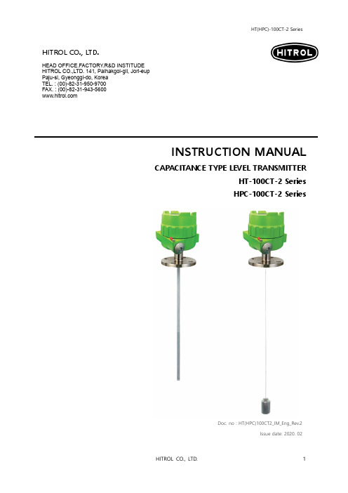
Doc. no : HT(HPC)100CT2_IM_Eng_Rev.2Issue date: 2020. 02HITROL CO., LTD.HEAD OFFICE.FACTORY .R&D INSTITUDE HITROL CO.,LTD. 141, Palhakgol-gil, Jori-eup Paju-si, Gyeonggi-do, Korea TEL. : (00)-82-31-950-9700 FAX. : (00)-82-31-943-5600 INSTRUCTION MANUALCAPACITANCE TYPE LEVEL TRANSMITTERHT-100CT-2 Series HPC-100CT-2 SeriesTable of contentsOverview (3)Characteristics (3)Operating Principle (3)Specifications (4)Weather-Proof Version (4)Ex -Proof Version (4)Amplifier Specification (5)Product Composition & Technical Data (6)Installation (8)Metal Tanks (10)Non-metal Tanks (10)Wiring & AMP Composition (11)Failure Check & Maintenance (18)Product Check (18)Failure Check (18)Precautions for Removal (18)Precautions for Transportation & Assembly .. 19 Precautions for Installation (19)Precautions for Grounding ......... 19 Safety and Environment (19)Marking (20)User Training (20)Warranty and Contact (20)OverviewCharacteristicsOperating Principle■Widely used to measure various liquid levels■Strong structure and semi-permanent life cycle due to moveless part■Various probe types for wide application■Easy installation of wire type. (HT-100CTW-2)■Applicable to corrosive liquid■Interface measurement between water and oil is available■Applicable to explosive area (HPC-100CT-2 Series)■Have KC certificate and CE certificateHT(HPC)-100CT-2 Series is a Capacitance Type Level Transmitter which continuously measures liquid levels using of liquid’s dielectric constant. It can be easily installed and adjusted, and can be easily applied to corrosive liquids and widely used in general industries, chemical and oil plants.When there are two conductors insulated each other, the value of capacitance formed between two conductors is a function of the sizes of two conductors, relative location of two conductors and the dielectric constant of material placed between two conductors. Under the conduction that air of dielectric ε₁exists in the space between two concentric conductors, lower part of space between two conductors is filled material of dielectric constant ε₂as shown below, the change of capacitance is expressed as follows.ΔC =Since is a constant value as an initial condition, and get this value as K, ΔC becomes a function of level of material only. Therefore, level can be obtained through the measurement of ΔC.log D/d10(ε₂- ε₁X l)[pF]10log D/d(ε₂- ε₁): Dielectric constant of air: Dielectric constant of medium (contents): Height of tank: Level of medium (contents): Outer diameter of tank: Outer diameter of sensing probeε₁ε₂LIDdSpecifications Weather-Proof VersionEx-Proof VersionAmplifier SpecificationProduct Composition & Technical DataMaterial :PBT(Aluminum) [Housing][Connection] Material : AluminumDielectric Constant Valuewebsite .InstallationThe capacitance type level transmitter can be installed in screw (PT, NPT, PF) and flange (ANSI, JIS, DIN) as well as tri-clamp and other various locations. Pay attention to the following matters during installation.■ Product shall be installed at the place far from inlet in order to avoid the malfunction.(a) ■ Protection tube shall be applied if there is a flow or slopping of the medium of the tank. (b) ■ Probe shall be installed within Max. 300mm from the tank wall and ground tube type shall be applied if the distance between the tank wall and sensing probe is far or the tank material is non-conductive. (c)■ Ground rod type shall be used for corrosive liquid. (d)■ Bracket insulated to a sensing probe shall be installed at the bottom of probe in order tofix it if the probe length is long or there is slopping of medium in the tank. (e)■ Ground tube or ground rod type shall be applied for concrete or non-conductive tank as per above figure. (g)■ Ground tube type shall be applied for ball tank and external chamber shall be installed forside mounting of tank. (h)■ When side mounting, the chamber shall be installed. (i)(g)(i)(h)■Metal Tanks (Conductive tank)When installing on a conductive tank, the transmitter housing and tank shall be grounded as shown below.■Non-metal tanks (Non-conductive tank)When installed on a non-conductive tank, use the ground tube (rod) or ground wire type.Also, the transmitter housing and tank shall be grounded as shown below.Wiring & AMP Composition■ Set Menu Function: Level : Distance0.0 ~ 95.0% or 4.000 ~ 19.200 mA setting [T able 1] Setting Menu List■ Module Composition- Make sure to connect the power with correct polarity (+, -), and the power supply shall be between +17V ~ 40V . - Do not connect the wire with the power connected.1. S : Function setting / Save the setting2. M : Mode Change / Cancellation3. ▲ : Span Set / Setting the value left / up4. ▼ : Zero Set / Setting the value right / down5. LCD : Display of operating and setting status6. LED : Display of power and status7. UART : Communication port of HT-100CT-2 setup and operation status 8. PWR : For supply power and current output / check for output current 9.N/A : Not used■ Operating methodThe cursor moves sequentially whenever the button is pressed. The order of movement is as follows.mA → % → m → ft → → → mA → % →…□ Into the Setting MenuIn the Setting Mode, press button for 1 second then the green LED will be flickering and you can go into the Setting Menu.□ Return to the Setting ModeIn the Setting Menu, press button for 1 second then the green LED will be flickering and you can go back to the Setting Mode.□ Select the Setting Menu⏹ In the Setting Menu, use / buttons to select the user setting function. ⏹Pressingbutton for 1 second will enter the function.About 1 sec./About 1 sec.About 1 sec. Display mode Cursor SegmentBar graph(User setting)(User setting)□ Change the User SettingIf just 1 digit is flickering , it can be moved between the digits. If full digits are flickering , it can only be set up to the specified number.□ User Key Button■ Height SettingChange of digitsand valueLevelThis refers to the direction in which the medium is raised based on the bottom of the tank.Zero HeightThe distance from the bottom of the tank to the zero point is called “Zero Height ”.Span HeightThe distance from the bottom of the tank to the span point is called “Span Height ”.T ank HeightThe distance from the bottom of the tank to the top of the tank is called “T ank Height DistanceThis refers to the direction of the downing of the medium from the top of the tank.[T able 2] Key Button Guidance□ Zero, Span Quick Setting■ Zero Setting■ Span Setting■ Others▶ Zero & Span can be set regardless of display mode status▶ It can set, save, and cancel the values. (Refer to T able 2) ▶ The level shall not be changed when Zero & Span are setting.mA SettingPercent Setting■ UART MonitoringYou can only check the state of the adjusted setting values using your PC or Smartphone, and the execution method is the same. (Password: 1975)Run screen configuration: You can check the sensor measurement status, sensitivity setting value, relay setting status, etc.■ Monitoring using a PCComponent – PC, USB Extension cable (typical USB to Micro USB B), UART ADAPTORZero SettingSpan SettingPress for 1 sec.Press for 1 sec.Press for 1 sec.Press for 1 sec.Input the valueInput the value[USB Extension cable][HT-100CT-2 PC UART Compositions]No. No. ContentsContentsSettingSetting[HT-100CT-2 PC UART Launch Screen Compositions]OutputInput[A Description of the Current Operating Status (##Err State)][HT-100CT-2 PC UART Launch Screen Compositions Function]Unit SetSetSet SetHeight Set (Based on level)Height Set (Based on level) Height Set (Based on level)Function SetSetAdjustmentAdjustmentAdjustmentSelectResetCapacity Value of Current MeasuredCapacity Value of Span SettingCapacity Value of Zero SettingCurrent Output of Current V alue (01. B a s e d o n O u t p u t S e l e c t S e t t i n g ) Current Output of P ercentage V alue (01. B a s e d o n O u t p u t S e l e c t S e t t i n g )Current Output of Length V alue (01. B a s e d o n O u t p u t S e l e c t S e t t i n g )Current Output of Feet V alue (01. B a s e d o n O u t p u t S e l e c t S e t t i n g )Current Operating StateNormal operationProblem for sensing B el ow or ab ov e t he set v a l ue o f Z er o or S p a n Abnormal settingSensor cable open circuit, short, broken probe insulation, module sensor failure, etcNAMUR ME43 Caution area (below 4mA, above 20mA)Zero, Span conversely set stateNo.ContentsDescriptionRemarks■Monitoring using a SmartphoneComponent – Smartphone (Android OS), OTG, USB Extension cable (typical USB to Micro USB B), UART ADAPTORApplication – Refer to “Serial USB Terminal Install & Setting Guide”[USB Extension cable][HT-100CT-2 Smartphone UART Compositions][Enter PW and Fly command]Continue[Open App] [Home screen] [Select the UART Connection] [Enter the password] [Operation screen][HT-100CT-2 Smartphone UART Launcher][Enter exit and Fly command][Enter exit command] [End of program] [Select the UART Disconnection][HT-100CT-2 Smartphone UART Exit]Failure Check & MaintenancePrecautions For Removal ■Check the level and presence of medium in the tank before removing it.■Wear gloves when removing it, to prevent a burn.■If there is explosive gas atmosphere, do not open the cover.■Disassemble work shall be done with the power off.■Make sure than any O-ring or gasket is not damaged while opening or closing the cover of product.■Product CheckThe major parts of the HT(HPC)-100CT-2 Series level transmitters to be inspected are divided into the sensor element and the transmission element. The life spans of major parts vary with user environments and can be used in optimum conditions through periodic inspections. Therefore, the user shall maintain and repair the product through periodic inspections conducted at least once a year. In addition, check for the exterior of the product like visual damage. If the medium or foreign substance is attached to the probe, it will cause bad accuracy, so it shall be removed regularly. Be careful not to damage the Teflon part during removal.■Failure CheckThe level of measured object changes, but the output does not change.▶Insufficient power supply▶Wrong adjustment of ZERO and SPANOnly a slight change of output to the change of level of medium is present.▶Wrong adjustment of ZERO and SPAN▶A slight change of probe ΔC valueNo change of level, but output fluctuation is present.▶Wrong grounding▶Noise on the lines▶Extreme fluctuation of medium▶Bad insulation of probeOutput indicates full (20mA) of higher regardless of the change of level of the medium.▶Wrong adjustment of ZERO and SPANPrecautions forT ransportation& AssemblyPrecautions for InstallationPrecautions for Grounding (Ex-proof)Safety and Environment ■Precautions for Use- Make sure to connect the product and vessel using required tools for sure.- Keep the lock key safe and make sure that it is locked.- Do not apply high impact to the product.■Precautions for Wiring- Make sure to wire contacts correctly. (Refer to Wiring)- Wire and supply the power to the device after checking the specifications.- Pay attention to prevent electric shock.■Disposal of Product- Make sure to separate the amplifier and main unit from housing before disposing the products. Also, the amplifier shall be detached and discard the metal and non-metallic materials. No part (ex. Mercury switch) has influence on the environment, so no special attention is required.■Pay special attention to prevent any impact on the device during transportation or assembly.■Pay attention to prevent any damage to any packing when transporting or mounting the machine to the vessel.■Use the same standard flange or screw.■Make sure to insert washers between bolts and nuts to prevent loosening.■Make sure to insert gaskets between flanges.(Select the gaskets in consideration of temperature of content and pressure of vessel.)■Install an Ex-proof product only in an Ex-proof zone.■After the installation is complete and the cover of the product is assembled, power it on.Please do not apply high impact to the product.■When connecting to an external ground, the ground wire shall be 4㎟(4mmSQ).Make sure to insert a washer if the terminal lug is removed from ground terminal and then re-connected. (Loosening prevention)HEAD (Weather-proof) HEAD (Ex-proof)External ground 4㎟(4mmSQ)MarkingUser TrainingWarranty and Contact■Warranty and ServiceThis product is subject to the warranty for 2 years of shipments and unpaid service will be provided for any damage found under normal operating conditions. If it is not about the failure of product, the service charge will be payable.You can request A/S at our website or by contacting our headquarters.■Headquarters ․Factory ․Laboratory Contact NumberAddress: HITROL CO., LTD 141, Palhakgol-gil, Jori-eup, Paju-si, Gyeonggi-do, Korea TEL: 031-950-9700 (Headquarters & A/S)FAX: 031-950-9796 ~ 9799 (Headquarters & A/S)■Product Identification- The product identification mark is attached onto the housing and shows the model name, serial number, working temperature, working pressure, and matters regarding output. The serial number is a unique manufacturing number for the identification of products.The fluid temperature of the container shall be up to 80℃for Weather-proof type. For high temperature, the fluid temperature shall not exceed 150℃. In addition, make sure that the ambient temperature of housing is kept at -20℃~ +60℃.An Ex-proof product is pressure-resistant and Ex-proof type, so never open the coverduring operation.Do not apply the Non Ex-proof product in an Ex-proof zone.Ex-proofWeather-proof。
液位继电器说明书

液位继电器说明书篇一:JYB系列液位继电器使用说明书JYB系列液位继电器使用说明书JYB系列液位继电器型号定义:工作电压42X56X10940.5X62X97设计序号(系列代号;见表)二.工作特性与工作原理本系列电子式液位继电器采用进口集成电路。
通过检测水阻的方法,控制继电器自动接通水泵电源进行供水,水满后自动切断水泵电源停止供水。
由于采用交流辅助电源作为有源控制探头,增强了产品抗干扰能力和产品远距离控制的能力。
采用大功率继电器输出,可直接控制1KW以内的水泵正常工作,采用螺钉或标准导轨安装,使用方便。
三.安装。
使用操作说明供水方式接线时,低端探头放在水池的底部,假如要把水池中的水用光后再打水,尽量可把中端探头靠近水池的底部,如需要水池中水位始终在高处,可调整中端探头的高度,高端探头为水池打水最高度的限制,当水池的水打满到高端探头时,水泵停止打水,当水池中的水用到低于中端探头时,水泵又开始打水,严禁自来水或外界无水时继电器工作,否则时间过长将烧坏水泵。
排水方式接线时,低端探头放在水池的底部,假如要把水池中的水排光,尽量可把中端探头靠近水池的底部,当外界的水流满至高端探头时,水泵开始排水,当水池中的水位排到低于中端探头时,水泵停止工作。
四.接线图JYB714、JYB714A供水方式接线图JYB714、JYB714A排水方式接线图篇二:C61F-GP说明书篇三:仪表说明书HC系列智能测控仪使用说明书北京京汇川仪表科技有限公司地址(Add):北京海淀区知春路甲48号盈都大厦C座1-11A电话(TEL):010-8212461982121435 58731899传真(FAX):010- 82124619一、概述HC—100智能测控仪是智能型、高精度的数显温度、压力、液位测量控制仪表,与温度、压力、液位传感器及变送器配接可构成各种量程和规格的温度、压力、液位测控系统。
HC—100智能测控仪的输入信号通过参数设置不需用户做硬件跳线,输入端子只需3个就能满足热电偶、热电阻、0~10mA或4~20mA标准电流、0~5V、1~5V标准电压信号的要求。
XMT100说明书
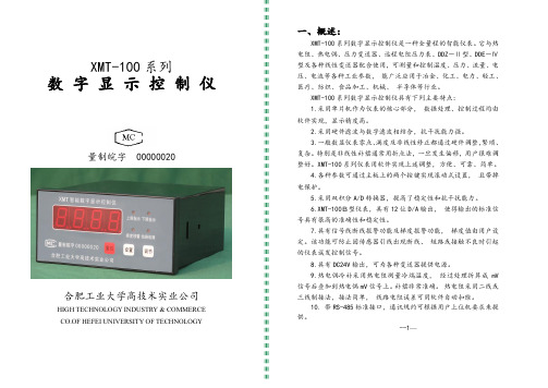
1.6 XMT-102A 型热电阻表零点、满度的调准方法:
将电阻箱接在仪表后面端子上,(以 Pt100 热电阻为例),先将电 阻箱调在 100Ω阻值上(零点对应欧姆值),调节“调零电位器”使 仪表显示为 0℃,然后将电阻箱调到满量程对应的电阻值上,(Pt100 量程为 150 ℃, 对应的电阻值为 157.33Ω),量程值和对应的欧姆 数参见附表 1。调节“调满电位器”,使仪表显示为对应的满度值。 然后再将电阻箱调在 0℃对应的电阻值上(如 pt100 零度时对应电阻 值为 100Ω),仪表显示应在 0℃左右,误差在允许值范围内,则校准 完成,否则要重复上述调整过程。
变送器
由用户选择
高低限 报警
继电器 标准信号输出
--4--
四、工作原理:
由传感器或变送器输出的模拟信号经放大后送到 A/D 变成数字 信号后,由单片机进行处理,包括数字滤波, 非线性补偿,热电偶 冷端补偿,热电阻的线路电阻修正等, 得出准确的测量值后再送去 显示、报警或控制。
原理框图见图一:
D/A 转换
4. XMT-101B、XMT-102B 温控仪的调准方法:
4.1 XMT-101B、XMT-102B 温控仪的参数设置、零点和满度调准 方法与 XMT-101A、XMT-102A 完全相同。
4.2 XMT-101B、XMT-102B 温控仪输出 0-10mA 或 4-20mA 标准信 号的调准方法参见图 6:
-10-
附1:不同传感器的零点和满度值:
传感器
G Cu50 Pt100
T E K S B
零点
53Ω 50Ω 100Ω
0 0 0 0 0
满度
86.79Ω 82.13Ω 157.33Ω 20.869mV 76.358mV 41.269mV 17.942mV 13.585mV
gl-100超声波液位计说明书

gl-100超声波液位计说明书ALT-GL-100超声波液位计超声波液位计是由微处理器控制的数字液位仪表。
在测量中超声波脉冲由传感器(换能器)发出,声波经液体表面反射后被同一传感器接收或超声波接收器,通过压电晶体或磁致伸缩器件转换成电信号,并由声波的发射和接收之间的时间来计算传感器到被测液体表面的距离。
由于采用非接触的测量,被测介质几乎不受限制,可广泛用于各种液体和固体物料高度的测量。
ALT-GL-100超声波液位计,超声波液位计可采用二线制、三线制或四线制技术,二线制为:供电与信号输出共用;三线制为:供电回路和信号输出回路独立,当采用直流24v供电时,可使用一根3芯电缆线,供电负端和信号输出负端共用一根芯线;四线制为:当采用交流220v供电时,或者当采用直流24v供电,要求供电回路与信号输出回路完全隔离时,应使用一根4芯电缆线。
直流或交流供电,具有4~20mADC,高低位开关量输出。
量程范围:0-50米,多种形式可选,适合各种腐蚀性、化工类场合,精度高,远传信号输出,PLC系统监控。
ALT-GL-100超声波液位计,超声波液位计工作原理是由超声波换能器(探头)发出高频脉冲声波遇到被测物位(物料)表面被反射折回反射回波被换能器接收转换成电信号.声波的传播时间与声波的发出到物体表面的距离成正比.声波传输距离S与声速C和声传输时间T 的关系可用公式表示:S=C×T/2.由于发射的超声波脉冲有一定的宽度,使得距离换能器较近的小段区域内的反射波与发射波重迭,无法识别,不能测量其距离值。
这个区域称为测量盲区。
盲区的大小与超声波物位计的型号有关。
探头部分发射出超声波,然后被液面反射,探头部分再接收,探头到液(物)面的距离和超声波经过的时间成比例:距离[m] = 时间×声速/2 [m]声速的温度补偿公式:环境声速= 331.5 + 0.6×温度现场条件在下面的任何一种情况,要注意:有泡沫的液体/固体周围有强电压,强电流,强电磁干扰,尽量避免高电压,高电流及强电磁干扰大风和太阳直晒强震动上海威尔太超声波液位计是由微处理器控制的数字物位仪表。
多个串口设备数据的连续采集

数据名称
数据类型
数据长度(byte)
系数
无符号整数
2
量程
浮点数
采样周期
无符号整数
2
扭矩报警值
浮点数
4
转速报警值
无符号整数
2
小电机转速
无符号整数
2
定时打印时间
无符号整数
2
转速模拟输出范围
无符号整数
2
标定温度
无符号整数
1
使用温度
无符号整数
1
14:写模拟通道量程。仪器收到命令后准备接收8个通道的量程表。每个量程2个 字节,共16个字节。数据类型是无符号整数,高位在前。低14位表示数值大小, 最高2位表示小数点位置。小数点位置为0,有0位小数点;小数点位置为1,有1位 小数点,小数点位置为2,有2位小数点。上位机应按上述读模拟通道量程的顺序依
常用的循环冗余校验标准多项式为: CRC-16:X16+ X15+X2+1 CRC-CCITT:X16+X12 +X5+1 CRC-32:X32+X26+X23+X16+X12+X11+X10+ X8+X7+X5+X4+X2+X+1
其中CRC-16多项式对应多项式码为1000 0000 0000 0101(0x8005),CRC-CCITT 对应的多项式码为0001 0000 0010 0001(0x1021)。
表2.4.1 发送给HC100的数据格式
EOT 仪表编号(十位) 仪表编号(个位) R 参数
04H 30H
31H
52 30H H 30H
HC—100智能测控仪

HC—100智能测控仪说明书目录一、概述 (1)二、主要技术指标 (1)三、型号说明 (3)四、操作说明 (4)五、报警 (8)六、变送输出 (9)七、打印功能 (9)八、通讯说明 (10)九、举例 (11)十、端子接线 (13)十一、关于HC-600智能光柱调节仪的几点说明 (16)十二、常见故障处理 (17)一、概述HC—100智能测控仪是智能型、高精度的数显温度、压力、液位测量控制仪表,与温度、压力、液位传感器及变送器配接可构成各种量程和规格的温度、压力、液位测控系统。
HC—100智能测控仪的输入信号可通过内部微型继电器任意改变,输入端子只需3个就能满足热电偶、热电阻、0~10m A或4~20m A标准电流、0~5V、1~5V标准电压信号的要求。
主要特点:◆采用当今最先进的ATMEL单片微机作主机,减少了外围部件,提高了可靠性。
◆集多种输入型号、输出方式于一机。
◆采用W ATCHDOG电路、软件陷阱与冗余、掉电保护、数字滤波等技术,注重现场容错能力,使整机具有很强的抗干扰能力。
◆采用双四位LED数码显示,可同时显示测量值与报警点设定值。
二、主要技术指标:基本误差:0.2%FS±1个字分辨力:1、0.1显示:双四位LED数码管显示输入信号:标准电流0~10m A、4~20m A标准电压0~5V,1~5V热电偶K、S、B、T、E、J、WRE、N热电阻Pt100、Cu50、Cu100冷端补偿误差:±1℃报警输出:二限报警或四限报警,每个输出根据需要可设定为上限报警、下限报警或禁止使用,继电器输出触点容量AC220V/3A或AC220V/1A。
变送输出:4~20m A(负载电阻≤500Ω)、0~10m A(负载电阻≤1000Ω)1~5V、0~5V(负载电阻≥200KΩ)通讯输出:接口方式——隔离串行双向通讯接口RS485/RS422/RS232/Modem波特率——300~9600bps内部自由设定馈电输出:DC24V/30m A温度补偿0~50冷端温度自动补偿,误差:±1℃电源:开关电源85~265V AC功耗:4W环境温度:0~50℃环境湿度:<85%RH面板尺寸:160mm×80mm、96mm×96mm、96mm×48mm、72mm×72mm、48mm×48mm三、型号说明四、操作说明(一)面板说明HA-HA报警灯LA-LA报警灯OUT-输出指示灯COM- 通讯指示灯AT-自整定状态灯PV-测量值显示窗SV-设定值显示窗(二)上电自检⑴按仪表的端子接线图连接好仪表的电源、输入、输出、报警等接线。
单光柱液位显示控制仪说明书2014年

单光柱液位显示控制仪说明书2014年单光柱液位显示控制仪说明书目录一、产品概述 (3)二、技术参数 (4)三、产品特点 (5)四、安装及使用 (6)4.1 安装说明 (6)4.2 使用注意事项 (7)五、操作方法 (8)5.1 开机与关闭 (8)5.2 菜单操作 (9)5.3 设置液位报警 (10)5.4 设置报警延迟 (10)六、故障排除 (11)七、常见问题解答 (12)八、售后服务 (13)九、产品维护 (14)十、安全警示 (15)一、产品概述本产品为单光柱液位显示控制仪,可用于测量和显示液体或固体物体的高度及液位报警。
采用先进的光学原理,具有高精度、高可靠性和便捷的操作特点。
广泛应用于化工、石油、电力、冶金、水处理等行业中的液位监控与显示。
二、技术参数1. 输入电压:AC220V±10%,50Hz2. 量程范围:0-10米(可定制其他量程)3. 分辨率:1mm4. 精度等级:0.5级5. 输出信号:0-20mA、4-20mA、RS4856. 工作温度:-20℃ ~ +70℃7. 防护等级:IP658. 受力方式:法兰连接、法兰螺栓固定三、产品特点1. 采用先进的光学原理,测量精度高,误差小。
2. 内置液位报警功能,可根据用户需求设置报警点。
3. 具备RS485接口,可与上位机进行通讯,实现远程监控。
4. 简单的操作界面,直观显示液位高度,方便使用。
5. 采用优质材料制作,具有良好的耐腐蚀性和稳定性。
6. 适用于各种工业环境,具有较高的可靠性和稳定性。
7. 可根据用户要求定制不同的量程和输出信号。
四、安装及使用4.1 安装说明1. 将控制仪与液位传感器进行连接,确保连接牢固可靠。
2. 液位传感器的安装位置应与液体/物体的高度相对应,确保测量准确。
3. 接通电源后,进行电源线接线,确保接线无误。
4. 控制仪的液晶显示屏上会显示当前液位的数值。
4.2 使用注意事项1. 在使用过程中,应注意避免与强酸、强碱等有害物质接触。
gaohan液位显示器说明书

gaohan液位显示器说明书摘要:一、产品概述1.1 产品名称:高瀚液位显示器1.2 产品型号:GLS-1001.3 产品用途:用于实时监测储罐、容器等液位高度二、产品特点2.1 采用先进的超声波测量技术2.2 具有高精度、高稳定性、高可靠性2.3 支持多种输出方式,如:电流、电压、RS485 等2.4 抗干扰能力强,适应各种复杂环境2.5 结构紧凑,安装维护方便三、技术参数3.1 测量范围:0-10 米3.2 测量精度:±0.01 米3.3 工作温度:-20℃~+70℃3.4 工作电压:DC24V3.5 输出信号:电流0-20mA,电压0-5V,RS485四、安装与调试4.1 安装环境要求4.2 安装步骤与方法4.3 接线与参数设置4.4 调试与校准五、使用与维护5.1 使用注意事项5.2 常见故障排除5.3 定期维护与保养正文:【产品概述】高瀚液位显示器(GLS-100)是一款采用超声波测量技术的液位测量设备,具有高精度、高稳定性、高可靠性等特点。
该产品主要用于实时监测储罐、容器等液位高度,为工业生产、仓储物流等领域提供便捷的液位监控解决方案。
【产品特点】1.采用先进的超声波测量技术,测量结果准确可靠;2.具有高精度、高稳定性、高可靠性,满足不同环境下的测量需求;3.支持多种输出方式,如:电流、电压、RS485 等,方便与其他设备连接;4.抗干扰能力强,适应各种复杂环境,保证设备稳定运行;5.结构紧凑,安装维护方便,节省空间与成本。
【技术参数】1.测量范围:0-10 米,适用于各种储罐、容器等;2.测量精度:±0.01 米,保证测量结果的准确性;3.工作温度:-20℃~+70℃,适应不同环境温度;4.工作电压:DC24V,保证设备稳定运行;5.输出信号:电流0-20mA,电压0-5V,RS485,满足不同用户需求。
【安装与调试】1.安装环境要求:避免阳光直射、避免高温、避免潮湿、避免有腐蚀性气体和液体;2.安装步骤与方法:根据产品尺寸和安装要求,选择合适的安装位置,进行水平、垂直校准;3.接线与参数设置:按照接线图连接电源、输出信号等,并进行相关参数设置;4.调试与校准:通电后,观察显示器上的液位数值,如有偏差,进行校准。
液位检测仪表技术标准
Q/CDT液位检测仪表技术标准河北大唐国际王滩发电有限公司发布Q/CDT-1WT 106 0001-2010目次前言 (1)1 范围 (1)2 引用文件和资料 (1)3 概述: (1)4 技术规范............................................................ 错误!未定义书签。
5 零部件清册 (1)6 检修专用工器具 (1)7 液位检测仪表基本检修项目及质量要求 (2)8 试验项目与技术标准.................................................. 错误!未定义书签。
9 液位检测仪表运行维护................................................ 错误!未定义书签。
Q/CDT-1WT 106 0001-2010前言为实现河北大唐国际王滩发电有限公司企业设备技术管理工作规范化、程序化、标准化,制定本标准。
本标准由(人力资源部)提出。
本标准由设备部归口并负责解释。
本标准起草单位:设备部热工室。
本标准主要起草人:高春雷。
本标准是首次发布。
(液位检测仪表)技术标准1 范围本标准规定了(液位检测仪表)的概述、设备参数、零部件清册、检修专用工器具、检修特殊安全措施、检修工序及质量标准、检修记录等相关的技术标准。
本标准适用于液位检测仪表运行和检修的技术管理工作。
2 引用文件和资料下列文件中的条款通过本标准的引用而成为本标准的条款。
凡是注日期的引用文件,其随后所有的修改单(不包括勘误的内容)或修订版均不适用于本标准,然而,鼓励根据本标准达成协议的各方研究是否可使用这些文件的最新版本。
凡是不注日期的引用文件,其最新版本适用于本标准。
(DL/T774- 2004)-火力发电厂热工自动化系统检修运行维护规程1DL/T 656火力发电厂汽轮机控制系统在线验收测试规程DL/T 658火力发电厂开关量控制系统在线验收测试规程DL/T 659火力发电厂分散控制系统在线验收测试规程DL 5000火力发电厂设计技术规程DL/T 5190.5电力建设施工及验收技术规范第5部分:热工自动化DL/T 657火力发电厂模拟量控制系统在线验收测试规程……3 概述:王滩发电公司1#、2#机组采用电接点水位计、差压式变送器等几种类型的液位检测元件,用以指示容器的液位。
智能秤重仪hc-100c-b2-fz说明书
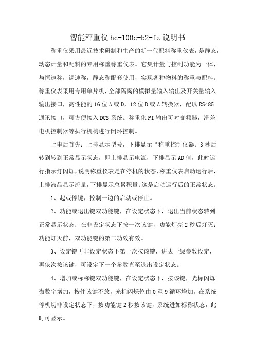
智能秤重仪hc-100c-b2-fz说明书
称重仪采用最近技术研制和生产的新一代配料称重仪表,是静态,动态计量和配料的专用称重称重仪表。
它集计量与控制功能为一体,与恒速称,调速称,静态称配套使用,实现各种物料的称重与配料。
称重仪表采用专用单片机,全部隔离的模拟量输入输出及开关量输入输出接口,高性能的16位A或D,12位D或A转换器,配以RS485
通讯接口,可方便接入DCS系统。
称重化PI输出可对变频器,滑差
电机控制器等执行机构进行闭环控制。
上电后首先:上排显示型号,下排显示“称重控制仪器;3秒后转到转到正常显示状态,即上排显示电流,下排显示AD值,此时运
行指示灯闪烁,说明称重仪表是在停机的状态,称重仪表启动运行后,上排液晶显示流量,下排显示总累积量:这是启动运行后的正常状态。
1、起或停键,控制一边的启动或停止。
2、功能或退出键双功能键,在设定状态下,退出当前状态转到
正常显示状态;在非设定状态下按一次该键,功能灯亮2秒后灯灭;功能灯灭前,双功能键的第二功效有效。
3、设定键再非设定状态下第一次按该键,进去一级参数设定,
再依次按该键,可设定下一个参数直至退出设定状态。
4、增加或标称键双功能键,在设定状态下,按该键,光标闪烁
微数字增加,按住该键不放,光标闪烁位由0至9循环增加。
在系统停机切非设定状态下,按功能键2秒按该键,系统进如标称状态,此时可显示。
5、光标或校零键双功能键,在设定状态下,按该键,光标右移一位。
在系统停机非设定状态下,按功能键2秒内按该键,系统键入校零状态;校零时上排显示校零倒计时间,下排液晶显示AD值,校零结束后自动报讯零点并推注校零状态。
智能数字显示液位控制仪说明书

智能数字显示液位控制仪说明书本厂产品是以单片微型计算机为核心、大规模集成电路为外围部件组成的高精度测控仪表,软、硬件采用多种抗干扰技术,采用EEPROM存储现场的工作数据,具有停、掉电数据不丢失,使用可靠性高的特点。
该仪表可与任何液位变送器配接组成液位测控系统。
功能简介:◆显示测量值◆设定液位控制值及输出控制方式◆可自由设定显示量程及小数点位数◆测量值变送输出,自由设定变送输出量程范围(可选功能)◆通过输入被测液体密度值实现不同液体液位的测量技术指标:◆开口尺寸:76*152;152*76;92*92;68*68;92*44共5种◆输入信号:线性电流信号或线性电压信号◆精度等级:0.5级◆采样速度:3次/秒◆电源电压:AC220V-10%--AC220V+10% ◆消耗功率:<=9W◆继电器触电容量:3A/220V(无感性负载)名词解释:二位式调节表(上限调节并带回差):仪表内只有一个上限继电器,当测量值高于设定值加P(P为上限回差值;后同)时,上限继电器中高通,同时指示灯“HA”亮; 当测量值低于设定值减P时,上限继电器中低通,同时指示灯“HA”灭.三位式调节表(上下限调节表):仪表内有两个继电器,可分别设定上限下限两个控制点; 当测量值高于上限设定值时,上限继电器中高通,同时指示灯“HA”亮; 当测量值低于上限设定值时,上限继电器中低通,同时指示灯“HA”灭. 当测量值高于下限设定值时,下限继电器中低通,同时指示灯“LA”灭; 当测量值低于下限设定值时,下限继电器中高通,同时指示灯“HA”亮范围调节表: 仪表内只有一个上限继电器,用此继电器可将被测量控制在设定的范围内,此种控制广泛用于不允许设备频繁启动的场合如控制水泵.控制过程如下:当测量值小于下限值时上限继电器中低通,“LA”灯亮;当测量值大于上限值时上限继电器中高通,“HA”灯亮;当测量值在上限值与下限值之间时,“LA”“HA”均灭,上限继电器维持原状态即:当测量值由下限值向上限值变化时,上限继电器维持中低通的状态; 当测量值由上限值向下限值变化时,上限继电器维持中高通的状态.上下限分别带回差调节表:在上限调节带回差表基础上增加下限调节并带回差,下限回差值用“A”表示; 当测量值高于上限设定值加P(P为上限回差值;后同)时,上限继电器中高通,同时指示灯“HA”亮; 当测量值低于上限设定值减P时,上限继电器中低通,同时指示灯“HA”灭;当测量值高于下限设定值加A(A为上限回差值;后同)时,下限继电器中低通,同时指示灯“LA”灭; 当测量值低于下限设定值减P时,下限继电器中高通,同时指示灯“LA”亮.仪表的操作:三个按键功能说明:“—”键设定/确认/提取键.该键的作用时进入仪表的设定状态,提取出原存的设定值,,待新的设定值修改完成后按该键确认修改有效并存入仪表内存,同时提取出下一个设定值.“∧”键显示数据加1功能键,单次按此键时数据加1;按住该键不动,显示数值将快速增加,松手后停止.“∨”键显示数据减1功能键,单次按此键时数据减1;按住该键不动,显示数值将快速减小,松手后停止.操作顺序:输入修改密码∶在测量状态下按一下“—”键,仪表即刻进入设定状态。
安德森仪器有限公司HB系列迷你液位传感器使用说明书

Instruction ManualAnderson Instrument Co., Inc.156 Auriesville Road Fultonville, NY 12072Phone: 800-833-0081Instrument Model Number Instrument Serial NumberSection 1 - Ordering MatrixSpan RangeFittingDiaphragm Material1 0”-20” to 0”-60” Water Column2 0”-60.1” to 0”-100” Water Column 30”-101” to 0”-160” Water Column005 2” Tri-Clamp1Stainless Steel - 316LHB0 Horizontal 1 Verticle (Diaphragm facing up)2 Other (Specify angle)Note: Calibration information must be providedat time of order. Inches of WaterColumn or Inches Height and Specific Gravity.1Section 2 - SpecificationsEnvironmental SpecificationsAmbient Operating Temperature Range: 40°F to 120°F (4°C to 49°C)Storage Temperature Range: -40°F to 250°F (-40°C to 121°C)Humidity: 0 to 95% RH, condensingOperating SpecificationsRange: HB1 0-20” to 0-60” Water ColumnHB2 0-60.1” to 0-100” Water Column HB3 0-101" to 0-160" Water Column Over-Range Capacity: 2.5 times Upper Range Limit Response Time: 200 uSec Accuracy: Factory calibrated to ±0.2% of Upper Range Limit (URL) Stabilized at 75°F (24°C)Process Temperature Limits: 32°F to 250°F (0°C to 121°C) Compensated 32°F to 200°F (0°C to 93°C)Material / ConstructionHousing:304 Stainless Steel, R a 40 maximum finish Wetted Parts:316L Stainless Steel, R a 25 maximum finish Process Connection:2” Tri-ClampOptional: Sealed Cable with 1/2" NPT Conduit ConnectionSection 3 DescriptionThe HB Series Mini-Level Transmitter is an integral unit designed to measure static head pressure (level) in Pasteurization Loop Balance Tanks and small Open Atmosphere Sanitary Storage Vessels. The unit converts head pressure exerted by the product into a proportional 4-20 mA DC signal. This signal may feed instrumentation such as controllers or digital indicators. The all stainless sealed design meets the demands of damp or wet applications, and may be directly washed down during normal cleanup. Units are typically shipped pre-calibrated from the Factory, with provisions provided for field calibration via onboard adjustment potentiometers (Pots).Section 4 WiringA 12 to 40 VDC loop power source is required for operation of the HB transmitter. If below 24 VDC, it is recommended that a regulated supply be utilized.HB mini level transmitters are provided with either the standard M12 5 pin quick disconnect receptacle or with a ½” NPT conduit connector option that includes a sealed four conductor, foil shielded sealed cable connection.Anderson recommends Molded cord-set P/N 42117H0025, 0050, 0100 for lengths 25ft, 50ft or 100ft. This is a premium molded cord-set designed to meet both the electrical and environmental requirements of the HB. Commercially available cord-sets may be used as long as shielding is connected to the attachment nut.For HB ordered with the conduit connection option conduit must be installed to meet environmental protection rating. Conductor assignments as follows:.connection(+)=LoopREDconnection(-)BLACK=LoopUsedGREEN=Not=NotUsedWHITEsensorat=AttachedGROUNDNOTE: If it becomes necessary to splice cable connections, be sure all joints are properly soldered and sealed from moisture. As copper easily becomes contaminated from typical cleaning solutions, poor quality connections will eventually affect 4-20 mA signal output of thetransmitter.Shield Ground(One Point Only)Section 5 Transmitter Electronic Zero CalibrationUpon installation, and at typical six month intervals, a Zero calibration adjustment must be performed. The required procedure is as follows:Tools required: Digital Multimeter (Known accurate)Fine - straight bladed screwdriverNOTE: Must be performed with the sensor installed in the vessel, with appropriate loop power applied.Be sure vessel is drained to a level at or below the sensor. The transmitter should be wired to the receiver at this point. To prevent possibly shorting receiver inputs, it is recommended that loop power be shutoff while making test equipment connections. At the receiver, remove the (-) BLACK transmitter lead. Connect the (+) RED meter lead to the transmitter lead just removed. Connect the (-) BLACK meter lead to the resulting empty terminal in the receiver. The digital multimeter should be set in the mA DC mode. At this point, apply loop power again taking note of the resulting meter reading. You should see 4.00mA registering on the meter display. If not, remove the screw at the end of the sensor labeled “ZERO”. Using the fine screwdriver, adjust the internal potentiometer until a reading of 4.00 mA is achieved. Once complete, replace the protective screw over the Zero potentiometer. Remove test equipment and install transmitter (-) BLACK lead back to receiver. Again, it is recommended that loop power be shut off while disconnecting equipment to prevent shorting of the receiver inputs.Figure 3 Zero AdjustmentsSection 6 Calibration Ranges and AdjustmentsThe HB series transmitter is typically supplied pre-calibrated from the factory. Calibration data is located on the information stamping on the side housing:CAL. RANGE: XXXXXXXXX (Factory Calibrated Range In Inches Of Water Column)Calibration checks may be performed in the field using known accurate pressure test equipment. Typical devices read out directly in Inches of Water Column where 27.7” Water Column equals 1 psig. As the required calibration pressures are very low, it is recommended that a test gauge having a direct Inches Water Column scale be used. This will give the greatest resolution. In some instances, it may be required to alter calibration, or perform calibration of the transmitter in the field. Keep in mind that two ranges exist. A transmitter supplied in the lower range cannot be re-spanned to operate in the higher range, and vice versa. Calibration adjustments within the same base range are allowed. The procedure for adjustment is as follows: Calibration Using Pressure Simulator· Be sure sensor is properly wired to loop power - remove Zero and Span protective cap screws· Attach multimeter as in Figure 3 (Readout in mA DC)· Attach pressure calibration equipment· Orient sensor as close as possible to position as if it were installed in vessel· Perform ZERO potentiometer adjustment with NO pressure on transmitter (Meter to read 4.00 mA)· Apply test pressure to transmitter· Perform SPAN potentiometer adjustment on transmitter (Meter to read 20.00 mA)· Replace sensor into vessel· Perform ZERO potentiometer adjustment with NO pressure on transmitter (Meter to read 4.00 mA)· Zero and Span are non-interactive - calibration is complete - replace protective cap screws Calibration Using Product in Vessel· Be sure sensor is properly wired to loop power - remove Zero and Span protective cap screws· Attach multimeter as in Figure 3 (Readout in mA DC)· Perform ZERO potentiometer adjustment with NO product on transmitter (Meter to read 4.00 mA)· Fill tank to capacity with PRODUCT· Perform SPAN potentiometer adjustment on transmitter (Meter to read 20.00 mA)· Zero and Span are non-interactive - calibration is complete - replace protective cap screws Calibration Using Water in VesselSpecific Gravity = (Pounds Per Gallon for Product / 8.345)· Calibration with water in a vessel that will hold another product requires Specific Gravity correction · Determine Specific Gravity, or calculate if Pounds Per Gallon provided· Correct for Specific Gravity: [ (16.00 mA / Specific Gravity) + 4.00 mA ] = Expected mA Signal · Be sure sensor is properly wired to loop power - remove Zero and Span protective cap screws· Attach multimeter as in Figure 3 (Readout in mA DC)· Perform ZERO potentiometer adjustment with NO product on transmitter (Meter to read 4.00 mA)· Fill tank to capacity with WATER· Perform SPAN potentiometer adjustment on transmitter (Meter to read result of calculation per-formed above)· Zero and Span are non-interactive - calibration is complete - replace protective cap screwsContact Anderson Instrument Technical Services for further assistancePlease have Model and Serial number availableWarranty and Return StatementThese products are sold by The Anderson Instrument Company (Anderson) under the warranties set forth in the following paragraphs. Such warranties are extended only with respect to a purchase of these products, as new merchandise, directly from Anderson or from an Anderson distributor, representative or reseller, and are extend-ed only to the first buyer thereof who purchases them other than for the purpose of resale.WarrantyThese products are warranted to be free from functional defects in materials and workmanship at the time the products leave the Anderson factory and to conform at that time to the specifications set forth in the relevent Anderson instruction manual or manuals, sheet or sheets, for such products for a period of one year.THERE ARE NO EXPRESSED OR IMPLIED WARRANTIES WHICH EXTEND BEYOND THE WARRANTIES HEREIN AND ABOVE SET FORTH. ANDERSON MAKES NO WARRANTY OF MERCHANTABILITY OR FIT-NESS FOR A PARTICULAR PURPOSE WITH RESPECT TO THE PRODUCTS.LimitationsAnderson shall not be liable for any incidental damages, consequential damages, special damages, or any other damages, costs or expenses excepting only the cost or expense of repairs or replacement as described above. Products must be installed and maintained in accordance with Anderson instructions. Users are responsible for the suitability of the products to their application. There is no warranty against damage resulting from corrosion, misapplication, improper specifications or other operating condition beyond our control. Claims against carriers for damage in transit must be filed by the buyer.This warranty is void if the purchaser uses non-factory approved replacement parts and supplies or if the pur-chaser attempts to repair the product themselves or through a third party without Anderson authorization. ReturnsAnderson’s sole and exclusive obligation and buyer’s sole and exclusive remedy under the above warranty is limited to repairing or replacing (at Anderson’s option), free of charge, the products which are reported in writing to Anderson at its main office indicated below.Anderson is to be advised of return requests during normal business hours and such returns are to include a statement of the observed deficiency. The buyer shall pre-pay shipping charges for products returned and An-derson or its representative shall pay for the return of the products to the buyer.An RMA (Return Merchandise Authorization) must be obtained from Anderson Customer Service before returning merchandise.Approved returns should be sent to: Anderson Instrument Co., Inc.Rd.Auriesville15612072Fultonville,NYRepairsATTN:Write RMA number on outside of package。
化工常见液位计介绍大全ppt课件
液位计以外的阀门; • 3、缓慢打开上部针型气阀直至全开 • 4、缓慢打开下部液相针型阀阀直至全开 • 5、进行液位计冲洗操作,并在冲洗中排除引压管堵的可能。 • 注意:打开阀门及冲洗操作时开阀要慢,防止液位计防漏装置动作引
资金是运动的价值,资金的价值是随 时间变 化而变 化的, 是时间 的函数 ,随时 间的推 移而增 值,其 增值的 这部分 资金就 是原有 资金的 时间价 值
资金是运动的价值,资金的价值是随 时间变 化而变 化的, 是时间 的函数 ,随时 间的推 移而增 值,其 增值的 这部分 资金就 是原有 资金的 时间价 值
资金是运动的价值,资金的价值是随 时间变 化而变 化的, 是时间 的函数 ,随时 间的推 移而增 值,其 增值的 这部分 资金就 是原有 资金的 时间价 值
浮筒式液位计
• 水校法
• 在浮筒上标注(水校)液位刻度浮筒下引 管中心位置为零点(0%)刻度位置;水校 量程L=(实际密度/水的密度)×浮筒长度, 从零点位置向上L高度为满量程(100%) 刻度;将L分为4等分,在浮筒上标注出来。
浮筒式液位计
• 当液位为高度H时,浮筒的浸 没深度为H-x,作用在杠杆上 的力为 Fx = W - A(H-x)ρg 式中 W ——浮筒的重量
• A ——浮筒的截面积; x ——浮筒上移的距离; ρ——被测液体的密度。
• 液位高度变化,作用在杠杆上 的力也跟着变化,扭力管产生 的角位移也随之变化,传感器 将角位移的变化量转化为420mA电流输出。
• ③浮子的挂扣脱落。由于脱扣,浮子沉到浮筒底部,扭力 管无挂重,相当于液位满量程时的情况。(显示110%) 处理:把浮子挂扣挂好后,投表,会运行正常。
HC100温湿度控制器使用说明书
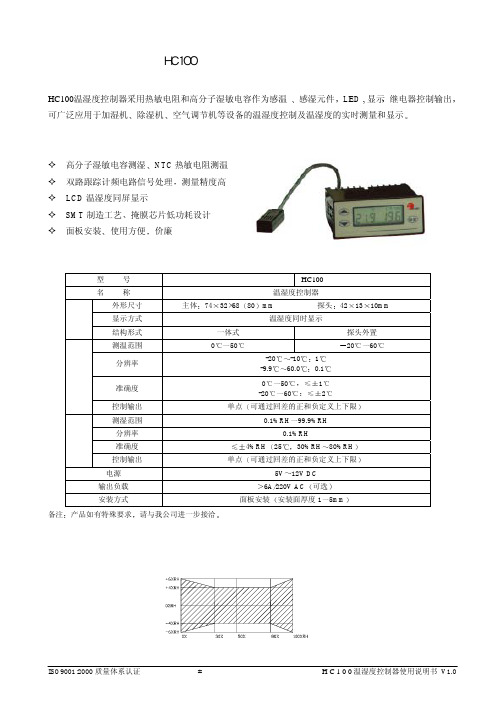
HC100温湿度控制器使用说明书HC100温湿度控制器采用热敏电阻和高分子湿敏电容作为感温感湿元件L E D ,显示继电器控制输出可广泛应用于加湿机除湿机空气调节机等设备的温湿度控制及温湿度的实时测量和显示特点高分子湿敏电容测湿NTC 热敏电阻测温双路跟踪计频电路信号处理测量精度高LCD 温湿度同屏显示SMT 制造工艺掩膜芯片低功耗设计 面板安装使用方便价廉性能指标和产品选型型 号HC100 名 称温湿度控制器外形尺寸主体7432×6880mm 探头421310mm显示方式温湿度同时显示结构结构形式一体式探头外置测温范围0502060分辨率-20-101-9.960.00.1准确度0501-20602温度控制输出单点可通过回差的正和负定义上下限测湿范围0.1%RH 99.9%RH分辨率0.1%RH准确度4%RH 2530%RH 80%RH湿度控制输出单点可通过回差的正和负定义上下限电源5V 12V DC 输出负载6A/220V AC 可选安装方式面板安装安装面厚度15mm备注产品如有特殊要求请与我公司进一步接洽湿度测量范围与精度外形mmA型 B型(探头外置)电气连接设定说明设定程序SET SET1)正常显示状态仅显示当前的温度和湿度(见外形图)2)设定湿度工作值在正常显示状态下按SET键当湿度数值闪烁温度部分无显示时即可设定湿度工作值此时湿度部分上面的H和L显示按+或-键设定所需的湿度工作值默认值为55%RH范围为1%RH99%RH3)设定湿度回滞值按SET键在温度数值默认值为-1%RH%RH和湿度部分上面的H闪烁时按+或-键设定回滞值范围-1-9%RH和19%RH在除湿状态回滞值设定范围为-1-9%RH湿度部分上面的H闪烁在加湿状态回滞值设定范围为19%RH湿度部分上面的L闪烁正常显示状态设定湿度工作值设定湿度回滞值设定温度工作值设定温度回滞值正常显示状态4)设定温度工作值按SET键当温度数值闪烁时湿度部分无显示时即可设定温度工作值此时温度部分上面的H和L显示按+或-键设定所需的温度工作值默认值为25范围为- 40605)设定温度回滞值按SET键在湿度数值默认值为-1和温度部分上面的H闪烁时按+或-键设定负回滞值范围为-1-9和19在加温状态回滞值设定范围为-1-9温度部分上面的H闪烁在降温状态回滞值设定范围为19温度部分上面的L闪烁注意事项a)设定时按键间隔时间最大为8秒超过8秒将自行返回正常显示状态b)在设定上述湿度参数后若同时按下+-键即确认湿度控制输出有效此时符号显示在设定温度参数后若同时按下+-键即确认温度控制输出有效此时符号显示再次按下+-键或符号不显示即控制输出无效安装示意品质保证质保期为12个月在质量保证期内基于正常使用和非人为损坏对产品提供免费工厂维护服务注意事项在安装和使用时避免直接接触热源/冷源安装和更换控制器时关闭电源建议产品在使用12个月后重新进行产品的检验和标定生产商北京宝力马传感技术有限公司 地址北京市崇文区定安里10号100075电话10-6721807467217060 传真10-67217032。
铭贝GM50H MK3多功能数显仪表详细使用说明书V1.0

GM50H MK3系列发动机多功能数显仪表操作使用手册版本更新记录序版本号发布日期更改内容1V1.02020-9-1首次发布本手册中使用的符号说明符号说明注意提示或提醒操作人员正确操作,否则有可能导致设备不能正确的工作。
小心表示如果不采取适当的预防措施,潜在的危险情况会损坏设备。
警告表示如果不采取适当的预防措施,潜在的危险情况可能会造成死亡、严重的人身伤害或重大的财产损失。
1、本设备的安装必须有专业人士进行。
2、在安装、操作仪表时,请先阅读完整的使用说明书。
3、对发动机进行任何维护和调试,必需熟悉所有设备、安全规范及做好事前预防措施,否则可能造成人身伤害或相关设备损坏。
4、发动机必须具备一个独立于本仪表系统的超速保护装置,以避免发动机失控造成人员伤亡或其它损害。
5、在仪表安装完成后,请测试并确认各项保护功能有效。
小心:1、请保持仪表电源的良好连接,不可与浮充电器共用电瓶正极各负极的连接线。
2、在发动机运转过程中,请勿断开电瓶,否则可能造成仪表损坏。
目录一、概述: (4)二、性能和特点 (4)三、参数显示 (5)四、报警保护 (5)五、参数规格 (5)六、外形结构及接线图 (6)七、安装指南 (8)八、面板与显示说明 (9)九、控制与操作说明 (10)十、警告和停机故障 (11)十一、参数设置 (13)十二、常见故障排除 (15)注:1、禁止在未经许可的情况下,传播本手册中的任何内容。
2、本说明书仅为提供相关信息,说明书中部分内容可能会不经通知而更改。
一、概述:GM50H MK3是一款轻巧、低价用于测量、显示发动机转速、水温、油温、油压、电池电压及发动机运行累计时的仪表。
本仪表具备多种保护功能,在发动机工作不正常时能有效的实施保护停车。
本仪表采用高亮度LED数码显示管,经久耐用。
通过按键可调整、设定参数,以满足不同应用场合的需求。
此外,采用欧式端子接线,以利于模块的安装、拆换。
二、性能和特点GM50H MK3系列仪表有两种型号:GM50H MK3:通过电阻式传感器采集发动机参数,具备报警保护功能,通过按键修改参数;GM50HR MK3:在GM50H MK3的基础上,增加RS485接口,可通过PC软件监控发动机参数和设置运转参数,可通过PC软件监控发动机参数和设置运转参数;主要特点如下:◆采用32位高性能单片机控制;◆5屏4位高亮度数码管显示测量值;◆超速、低油压、高水温等多种保护功能;◆通过发电频率可换算显示为转速;◆内置多种传感器曲线可选,并可以自定义传感器参数曲线;◆具备3路传感器模拟量输入,其中油压传感器兼容电压信号输入;◆通过面板按键可修改所有参数;◆具备RS485接口,利用MODBUS协议可以实现远程数据监测(仅GM50HR MK3具备);◆具备大电流报警继电器,一常开一常闭输出,方便用户应用;◆标配防水圈,安装后面板防护性能达到IP65级别;◆模块化设计:所有连线通过欧式接线端子完成,设备的装配、连线、维修、更换非常容易和方便;三、参数显示◆发动机转速;◆发动机机油压力;◆发动机冷却水温度;◆发动机机油温度;◆发动机电瓶电压;◆发动机累计运行时间;四、报警保护◆超速报警◆低油压报警◆水温高报警◆机油温高报警◆传感器开路报警◆低电瓶电压警告项目参数工作电压DC8V至36V连续供电整机功耗待机:24V:MAX1W 工作:24V:MAX 1.5W交流电压输入一相两线30VAC-360VAC发动机转速信号范围50-10000Hz(AC3~65V)最大累计运行时间99999.9小时(最小保存时间6分钟)报警继电器输出5Amp无源触点一常开一常闭输出工作条件-30-70℃储藏条件-40-85℃防护等级IP65:当仪表与控制屏之前加装防水圈时。
第九章液位检测仪表

(2)负迁移 形成原因是加隔离罐或采用法兰
式测压差。此时差压变送器的 正、负压室的压力分别为:
P P 气 H1gh 12g
P P 气h2 2g
于是正、负压室的压差为:
各种液位测量仪表检测示意图
9.2.1 差压式液位计
静压式液位传感器是基于流体静力学原理,通过液柱 静压的方法对液位进行测量。液位—压力转换的方式主要 有压力式和差压式。
若液位的高度位h,则液体底部的压力为:
PBgh
pPBgh
h
h p g
所以测得表压力p即可求得液位高度h。
1、压力式液位计
适用于敞口容器的液位测量,即直接测量容器底部压力得
1-内电极;2-绝缘套管;3-虚假水位;4-容器
(2)非导电液体的电容式液位计
液位为H时,总电容量为:
C2H20(LH)
lnD
lnD
d
d
液位为0时,总电容量为:
C0
2 0 L
ln D
d
当液位从0上升到H时,
非导电液体的电容式液位计原理图
电容的变化
1-内电极;2-外电极;3-绝缘套;4-流通小孔
Cx CC02(ln D 0)HKH
d
其中,0 ——空气介电常数; D, d ——分别为外电极内径和内电极外径。
9.2.4 霍尔式液位计
1、霍尔传感器的工作原理 霍尔电势
利用被测量来改变I或者B,再通过测量霍尔电势来确定 被测量。
2、霍尔液位计的工作原理
(1)液位产生的压力作用于弹性元件上。 (2)弹性元件带动霍尔元件(半导体薄片)在磁场中移动
- 1、下载文档前请自行甄别文档内容的完整性,平台不提供额外的编辑、内容补充、找答案等附加服务。
- 2、"仅部分预览"的文档,不可在线预览部分如存在完整性等问题,可反馈申请退款(可完整预览的文档不适用该条件!)。
- 3、如文档侵犯您的权益,请联系客服反馈,我们会尽快为您处理(人工客服工作时间:9:00-18:30)。
目录一、概述 (1)二、主要技术指标 (1)三、型号说明 (3)四、操作说明 (4)五、报警 (8)六、变送输出 (9)七、打印功能 (9)八、通讯说明 (10)九、举例 (11)十、端子接线 (13)十一、关于HC-600智能光柱调节仪的几点说明 (16)十二、常见故障处理 (17)一、概述HC—100智能测控仪是智能型、高精度的数显温度、压力、液位测量控制仪表,与温度、压力、液位传感器及变送器配接可构成各种量程和规格的温度、压力、液位测控系统。
HC—100智能测控仪的输入信号可通过内部微型继电器任意改变,输入端子只需3个就能满足热电偶、热电阻、0~10m A或4~20m A标准电流、0~5V、1~5V标准电压信号的要求。
主要特点:◆采用当今最先进的ATMEL单片微机作主机,减少了外围部件,提高了可靠性。
◆集多种输入型号、输出方式于一机。
◆采用W ATCHDOG电路、软件陷阱与冗余、掉电保护、数字滤波等技术,注重现场容错能力,使整机具有很强的抗干扰能力。
◆采用双四位LED数码显示,可同时显示测量值与报警点设定值。
二、主要技术指标:基本误差:0.2%FS±1个字分辨力:1、0.1显示:双四位LED数码管显示输入信号:标准电流0~10m A、4~20m A标准电压0~5V,1~5V热电偶K、S、B、T、E、J、WRE、N热电阻Pt100、Cu50、Cu100冷端补偿误差:±1℃报警输出:二限报警或四限报警,每个输出根据需要可设定为上限报警、下限报警或禁止使用,继电器输出触点容量AC220V/3A或AC220V/1A。
变送输出:4~20m A(负载电阻≤500Ω)、0~10m A(负载电阻≤1000Ω)1~5V、0~5V(负载电阻≥200KΩ)通讯输出:接口方式——隔离串行双向通讯接口RS485/RS422/RS232/Modem波特率——300~9600bps内部自由设定馈电输出:DC24V/30m A温度补偿0~50冷端温度自动补偿,误差:±1℃电源:开关电源85~265V AC功耗:4W环境温度:0~50℃环境湿度:<85%RH面板尺寸:160mm×80mm、96mm×96mm、96mm×48mm、72mm×72mm、48mm×48mm三、型号说明四、操作说明(一)面板说明 HA-HA 报警灯 LA-LA 报警灯 OUT-输出指示灯 COM- 通讯指示灯 AT-自整定状态灯 PV-测量值显示窗 SV-设定值显示窗 (二)上电自检⑴按仪表的端子接线图连接好仪表的电源、输入、输出、报警等接线。
⑵仔细检查仪表的接线,正确无误后方可打开电源。
⑶接通电源后仪表上排显示HELO 下排显示PASS字样表示仪表自检通过,如果显示-HH-表示超量限或断偶及热阻开路,仪表采用人机对话形式来输入参数,用各种提示符来提示应输入的数据。
(三)按键功能SET —在设定状态时,用于存贮参数的新设定值并选择下一个设定参数 ▲—在设定状态时,用于增加设定值▼—在设定状态时,用于减少设定值A/M—在设定过程中,按一下返回上一次设定操作,按下不动大于2秒钟则退出设定状态●—手动打印键或其他特殊用途(四)参数设定在设定状态下,仪表上排显示参数提示符,下排显示设定值;工作状态下,上排显示测量值(PV),下排显示可根据需要设定。
如果设定过程中12秒钟不改变参数,则仪表自动返回运行。
参数设定如下:⑴开锁:按下SET键,上排显示窗出现Loc,下排显示窗显示oFF,必须按▲键把oFF改成oN 后,才能修改报警点设定值,当Loc设定为oFF时,报警点设定值禁止修改,只能浏览。
⑵报警点设定:HA—第1报警点设定值。
LA—第2报警点设定值。
HHA—第3报警点设定值。
LLA—第4报警点设定值。
仪表具有两限报警或四限报警输出,报警输出方式有上限报警(即高于设定值报警动作)、下限报警(即低于设定值报警动作)和禁止使用三种。
报警输出方式由报警允许参数(HHAo、HAo、LAo、LLAo)来设定。
⑶报警点设定完毕后,按下SET键,上排显示-Cd-,下排显示1230,用▲和▼键将1230设成1234, 再按SET键才进入二级参数设置状态,输入其他值无效,这主要是为了防止现场非操作人员误修改参数。
⑷S n—仪表输入信号。
⑸dot—小数点设定,范围0~3。
⑹inPL—线性输入下限对应显示值,即仪表量程下限,范围-999~9999。
⑺inPH—线性输入上限对应显示值,即仪表量程上限,范围-999~9999。
⑻HAo—设定为—HH—表示高于第1报警点设定值时报警(上限报警),设定为—LL—表示低于第1报警点设定值时报警(下限报警),设定为OFF时表示此点报警禁止,未使用。
⑼LAo—设定为—HH—表示高于第2报警点设定值时报警(上限报警),设定为—LL—表示低于第2报警点设定值时报警(下限报警),设定为OFF时表示此点报警禁止,未使用。
⑽HHAo—设定为—HH—表示高于第3警点设定值时报警(上限报警),设定为—LL—表示低于第3报警点设定值时报警(下限报警),设定为OFF时表示此点报警禁止,未使用。
⑾LLAo—Ao设定为—HH—表示高于第4报警点设定值时报警(上限报警),设定为—LL—表示低于第4报警点设定值时报警(下限报警),设定为OFF时表示此点报警禁止,未使用。
⑿LdbC—冷端补偿选择,设成ON为需要冷端补偿,设成OFF为不需要冷端补偿。
当输入类型为热电偶时,LdbC必须设成ON。
⒀HY-H—第1报警点报警回差值(当HAo设为OFF时则此项关闭)。
⒁HY-L—第2报警点报警回差值(当LAo设为OFF时则此项关闭)。
⒂HYHH—第3报警点报警回差值(当HHAo设为OFF时则此项关闭)。
⒃HYLL—第4报警点报警回差值(当LLAo设为OFF时则此项关闭)。
⒄bS—变送输出方式,可选择1~5V、0~5V、4~20mA、0~10mA几种方式。
⒅bS-L—变送输出下限时对应的仪表量程下限。
⒆bS-H—变送输出上限时对应的仪表量程上限。
⒇oSEt—调零点校正系数范围-99.9~99.9,修正后显示值=修正前测量值+oSEt,出厂值oSEt=0.0(21)FSEt—调满度校正系数范围0.500~2.000,修正后显示值=FSEt×(修正前的测量值+oSEt),出厂值FSEt=1.000。
(22)Lb—数字滤波参数,设置范围为0~20,0没有任何滤波,1只有中间值滤波,2~20同时有取中间值滤波和二阶积分滤波。
Lb越大,测量值越稳定,但响应也越慢。
一般在测量值受到较大干扰时,可逐步增大Lb值,调整使测量值间跳动小于2~5个字。
在实验室对仪表进行计量检定时,则应将Lb设置为0或1以提高响应速度(23)Addr—通讯地址即仪表编号,范围1~99。
(24)bAUd—通讯的波特率,范围300~2400。
(25)LdiS—仪表工作时下排显示值,显示项目为HHA、HA、LA、LLA、Addr、OFF,如果此项设为OFF,则仪表工作时下排无显示,单显示仪表选择此方式。
例:把LdiS设为Addr则仪表工作时下排显示仪表通讯地址。
五、报警HA ⑴当仪表进入第1报警点报警状态时,HA指示灯亮,且相应的继电器(HA)常开触点闭合。
LA ⑵当仪表进入第2报警点报警状态时,LA指示灯亮,且相应的继电器(LA)常开触点闭合。
HHA ⑶当仪表进入第3报警点报警状态时,HA指示灯亮,同时上排测量值闪烁,且相应的继电器(HHA)常开触点闭合。
LLA ⑷当仪表进入第4报警点报警状态时,LA指示灯亮,同时上排测量值闪烁,且相应的继电器(LLA)常开触点闭合。
⑸报警回差(HY-H、HY-L、HYHH、HYLL)为避免测量值在报警临界点波动时报警输出频繁动作,仪表使用了报警回差参数。
Ⅰ、以第1报警点报警为例:此报警点报警方式设为上限报警(即HAo设为-HH-),当测量值大于HA+HY-H时,仪表进入报警状态,当测量值下降到HA值时仪表并未停止报警,只有在测量值低于HA—Hy-H时,仪表才解除报警状态。
Ⅱ、以第2报警点报警为例:此报警点报警方式设为下限报警(即LAo设为-LL-),当测量值下降到LA—HY-L时,仪表进入报警状态,当测量值上升到LA+HY-L时,仪表才解除报警状态。
六、变送输出仪表可把测量值变送输出为标准信号,输出形式由“bS”参数确定,测量值变送范围由“bS-L”及“bS-H”参数确定。
七、打印功能仪表的打印功能由仪表内增加的打印接口板及另配的打印单元(打印机及打印电源)完成。
仪表内置硬件时钟,停电不影响。
参数设置如下:⑴-Ht-—设定××月××日。
⑵-Lt-—设定××时××分,这样就提供给打印机一个起始时间,到时打印机会一起打印出来(××月××日××:××)。
⑶-Pt-—设定仪表定时打印周期,范围1~9999分,设为00时不打印。
注1:带打印功能的仪表才有此类参数。
注2:在仪表工作状态下,按下●键可实现即时打印。
八、通讯说明本仪表可另配RS232、RS422/485接口,直接与计算机通讯,数据格式为1个起始位﹑8个数据位﹑无奇偶校验﹑1个停止位﹑共11位。
所有数字变成ASCⅡ码传输:举例:仪表编号 Addr=01,测量值=123.4,则数据千位为31H、百位为32H、十位为33H、小数点为2EH,个位为34H、符号位2BH为正、2DH为负从仪表读数据指令格式:EOT+仪表地址编号+52H+ENQ[04,30h,31h,52h,05h]仪表返回:STX+仪表地址编号+符号位+测量值+校验码+ETX[02h,30h,31h,2bh,31h,32h,33h,2eh,34h,83h,03h]说明:⑴仪表编号由仪表中“Addr”参数决定,它为2位数字的ASCⅡ码。
⑵在命令及返回参数中的EOT,STX等均为一个ASCⅡ码,它们的码值为:STX=02H;ETX=03H;ENQ=05H;EOT=04H,R表示读ASCⅡ码值=82⑶数据参数值为符号位+4位有效位+小数点,共6位。
检验码为发送前9个字节之和。
⑷举例中校验码=02h+30h+31h+2bh+31h+32h+33h+2eh+34h.⑸以上所列内容为最常用的通讯方式,如果需要采用组态软件,请参见本公司的通讯协议说明。
九、举例①仪表配有通讯接口,用于液位控制,要求液位测量值值高于8米时第1报警点上限报警,低于2米时第2报警点下限报警,液位变送器类型为二线制4-20m A输出,对应0~9米,和计算机联网,仪表编号为01,波特率为2400,测量值无须校正,第1报警点报警回差值为0.02,第2报警点报警回差值为0.04,小数点为3位,滤波常数出厂值设为0,参数设定如下:HA=8.000 LA=2.000Sn=4-20 dot=3inPL=0.0 inPH=9.000HHAo=OFF HAo=HHLAo=LL LLAo=OFFHy-H=0.020 HY-L=0.040oSEt=0.000 FSEt=1.000L b=0 Addr=1 bAUd=2400②校正系数确定:仪表用pH值测量,将pH传感器分别插入pH值为4.00和9.18的标准缓冲液中,仪表对应的显示值分别为4.05和9.32,则零点和满度校正系数按下列方法确定:4.00=FSEt(4.05+oSEt)9.18=FSEt(9.32+oSEt)由上式可计算出:FSEt=0.98 oSEt=0.02十、端子接线⑴、A规格160×80×125尺寸的仪表⑵B规格96×96尺寸仪表A/S规格80×160×125尺寸的仪表⑶C规格96×48尺寸仪表⑷C/S规格48×96尺寸仪表⑸规格72×72尺寸仪表⑹F 规格48×48尺寸仪表注:⑴输入信号为热电偶、电压信号,接线方式相同⑵输入信号为热电阻、远传电阻,必须三线制接入⑶特殊要求的仪表,接线方式请以随机接线图为准。
