VF40100C中文资料
VB40100C中文资料

0.145 (3.68) 0.135 (3.43)
0.350 (8.89) 0.330 (8.38) 1.148 (29.16) 1.118 (28.40)
0.057 (1.45) 0.045 (1.14)
0.105 (2.67) 0.095 (2.41) 0.104 (2.65) 0.096 (2.45)
DELIVERY MODE Tube Tube Tube
Tape and reel Tube
Average Forward Current (A) Average Power Loss (W)
RATINGS AND CHARACTERISTICS CURVES (TA = 25 °C unless otherwise noted)
2.0
4.0
VB40100C 2.0
VI40100C 2.0
UNIT
V
µA mA µA mA
UNIT °C/W
ORDERING INFORMATION (Example)
PACKAGE
PREFERRED P/N UNIT WEIGHT (g)
TO-220AB
V40100C-E3/4W
1.85
ITO-220AB
50
VI40100C
40
VB40100C
V40100C
30
VF40100C
20
10
0
0
25
50 75 100 125 150 175
Case Temperature (°C)
Figure 1. Forward Current Derating Curve
2
18
16
D = 0.8
IT4010中文资料
INZOTEK超低EMI、无需滤波器、3W 单声道 D 类音频功放 功能说明IT4010IT4010 是一款超低 EMI、无需滤波器 3W 单声道 D 类音频功率放大器。
IT4010 采用先进的技术, 在全带宽范围内极大地降低了 EMI 干扰,最大限度地减少对其他部件的影响。
IT4010 内置过流保护、过热保护及欠压保护功能,有效地保护芯片在异常工作状况下不被损坏。
并 且利用扩频技术充分优化全新电路设计,高达 90%的效率更加适合于手机及其他便携式音频产品。
IT4010 无需滤波器的 PWM 调制结构及增益内置方式减少了外部元件、PCB 面积和系统成本。
IT4010 提供 MSOP8封装,额定的工作温度范围为-40℃至 85℃。
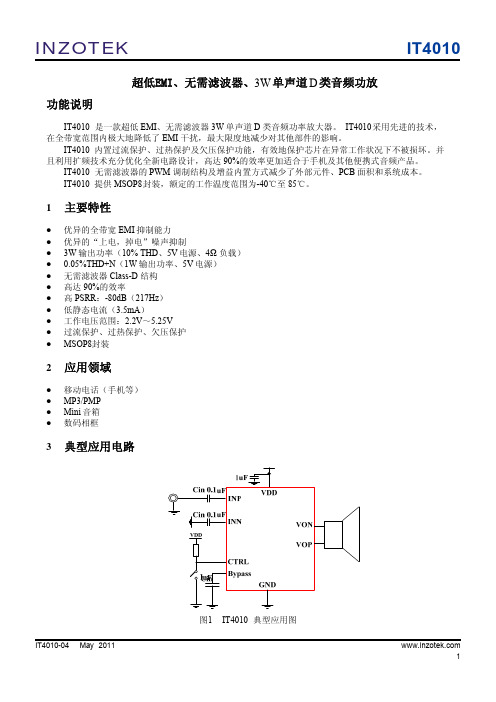
1 主要特性优异的全带宽 EMI 抑制能力 优异的“上电,掉电”噪声抑制 3W 输出功率(10% THD、5V 电源、4Ω 负载) 0.05%THD+N(1W 输出功率、5V 电源) 无需滤波器 Class-D 结构 高达 90%的效率 高 PSRR:-80dB(217Hz) 低静态电流(3.5mA) 工作电压范围:2.2V~5.25V 过流保护、过热保护、欠压保护 MSOP8封装2 应用领域移动电话(手机等) MP3/PMP Mini 音箱 数码相框3典型应用电路图1IT4010-04 May 2011IT4010 典型应用图 1IT40104INZOTEK参数 表1 芯片最大物理极限值 最小值 最大值 -0.3 -0.3 -65 6.0 VDD+0.3 150 150 260 190 -40 85 +/-8000 150 -150 单位 V V ℃ ℃ ℃ ℃/W ℃ V mA mA极限参数电源电压 VDD INP,INN,CTRL 引脚电压 最大结温 存储温度范围 引脚温度 (焊接 10 秒) 封装热阻JA(MSOP8) 工作温度范围 ESD 防护电压 Latch-up +IT -IT注 1:在极限值之外或任何其他条件下,芯片的工作性能不予保证。
Fujitsu fi-4010CU 消耗品替换与清洁指南说明书
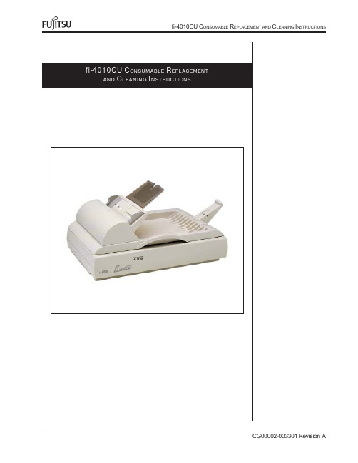
2K IT CONTENTSCotton Swabs Qty 1 100/packF1 CleanerIsopropyl AlcoholQty 1Cleaning Paper Qty 1 10/packLint FreeCleaning ClothsQty 2 20/pack Pad AssemblyQty 23C ONSUMABLES L ISTDescription Qty Life Fujitsu P/NPad Assembly 120,000 Pages CA06009-G009Note:Replacement Cycles are estimated guidelines established by testing with A4/Letter sized woodfree and wood based 17 lb paper. NCR or Carbonless paper has chemical composition which damages the Pad.Cleaning of the consumables and feed rollers will be required more frequently to avoid feed problems. Consumable life will be reduced ifNCR or Carbonless paper is scanned.C ONSUMABLES P AGE C OUNTDouble click the “Scanners and Cameras” Icon on the Control panel of the Host Computers Windows Operating System. Double click the “fi-4010CU” in the “Scanners and Cameras Properties” Display to display the Properties screen. Select the “Device Set” Tab.Pad Assembly4C ONSUMABLES P AGE C OUNT (CONTINUED)•Your computer will display the Properties for the fi-4010CU scanner.You can reset the Pad counter to 0 each time it is changed todetermine when it should be changed next.5R EPLACING THE P AD A SSEMBLYA defective or improperly installed Pad Assembly can cause misspicks,skew, or double fed documents. To replace the Pad Assembly perform the following steps.•Remove all documentsfrom the ADF PaperChute. Open the ADFby pulling the ADFbutton up.•Remove the PadAssembly by pressingboth sides of theclamp so the pad canbe pulled out.•Attach the new PadAssembly in reverse ofremoval. Be sure toseat the padcompletely to avoidjamming of paper being fed.Note:After replacement of any consumable reset the counter for that consumable by following the “Consumables Page Count” Section atthe front of these instructions to reset paper counts.6C LEANING L OCATIONS AND F REQUENCIESNote:The scanner will need to be cleaned every day (or possibly more than once a day) if the following paper is scanned.•Paper with special coating such as carbonless paper.•Paper with large amount of printing. (Heavy toner or ink)•Documents with toner that is not fused properly.C LEANING M ATERIALSFrequencyCottonSwabsF1 CleanerIsopropyl AlcoholCleaning PaperLint FreeCleaning Cloths7C LEANING THE R OLLERS WITH THE C LEANING P APER•Set the Hopper Guides tothe widest width possible.The cleaning papers are designed to remove only loose paper dust and ink from the rollers. Use the cleaning paper approximately every 1,000 sheets scanned. They are to be used in between the thorough cleanings of the scanner. Using the cleaning paper does not take the place of the more complete cleanings described later in this section•Spray the Cleaning Paper lightly with F1 Cleaner and place the Cleaningpaper against the right edge of the Hopper Guide. SCAN the cleaningpaper to feed it through the scanner’s ADF. Do Not Save These Images.This operation is used only to pass the cleaning paper through the paper feed path. Check the path to see if it needs further cleaning, if you find debris in the paper path perform this cleaning or the (C LEANING THE ADF WITH L INT -F REE C LOTHS ) in the following steps.•Place the Cleaning Paper against the Left Hopper Guide and perform theprevious step.8•Turn Scanner power off.•Open the ADF cover bypulling the ADF open.Disconnect the AC powerplug. Let the scanner cool forat least 15 minutes afteroperation. This is to preventburns to your skin as thelamps will heat the surface ofthe glass in the feed path.•Use F1 Cleaner (90% orhigher Isopropyl Alcohol) ona lint free cloth and clean theareas shown in the drawingbelow and to the right. (Seefollowing steps to cleanproperly)•Clean the Pad Assemblyusing a downward stroke inthe direction of documenttravel through the ADF(shown by the arrow in thedrawing to the right) with thelint free cloth moistenedlightly with F1 Cleaner (90%or higher Isopropyl Alcohol).C LEANING THE ADF WITH L INT-F REE C LOTHSNote:The glass surface inside the fi-4010CU ADF becomes hot during scanner operation. Before performing this cleaning turn off the scanner and disconnect the AC adapter from the power outlet, wait at least 15 minutes for the scanner to cool.C LEANING THE P AD A SSEMBLY.Pad Assembly9。
倍福PLC卡件介绍
AC-2——异步电机用高频MOSFET逆变器AC2代表了当今最为先进的技术(IMS功率模块,Flash内存,微处理器控制,Can Bus)。
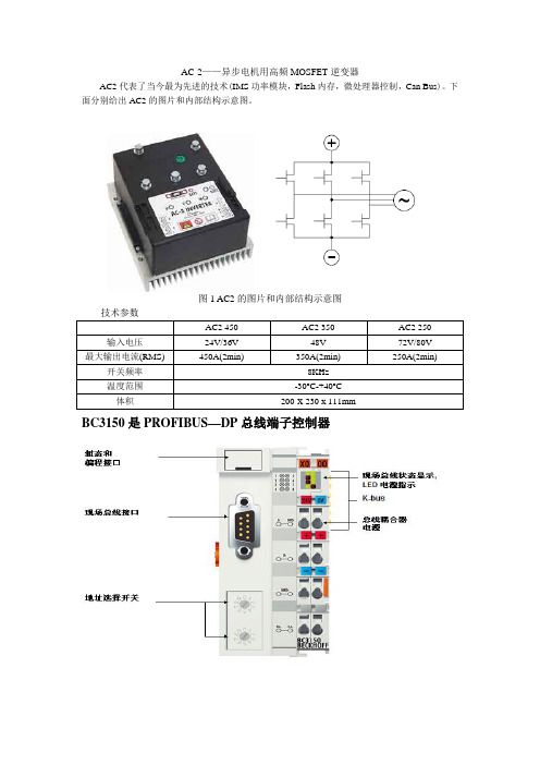
下面分别给出AC2的图片和内部结构示意图。
图1 AC2的图片和内部结构示意图BC3150是PROFIBUS—DP总线端子控制器总线端子控制器是带 PLC 控制功能的总线耦合器。
控制器有一个 PROFIBUS-DP 现场总线接口,可在 PROFIBUS-DP 系统中作为智能从站使用。
“紧凑型”总线端子控制器 BC3150 比较小巧而且经济。
BC3150 通过 K-BUS 总线扩展技术,可连接多达 255 个总线端子。
PROFIBUS 控制器自动检测波特率,最大可至 12 M波特率,使用两个地址选择开关分配地址。
总线端子控制器使用符合 IEC 61131-3 标准的 TwinCAT 进行编程。
组态和编程接口用于装载 PLC 程序,如果使用软件 PLC TwinCAT,则其 PLC 程序也可通过现场总线装载。
所连接的总线端子的输入/输出在 PLC 的缺省设置中被赋值。
可对每个总线端子进行配置,使其直接通过现场总线实现与上层控制单元的数据交换。
同样,预处理的数据也可通过现场总线实现总线端子控制器和上层控制器之间的数据交换。
BK3150是PRORIBUS—DP总线端子耦合器PROFIBUS-DP “紧凑型”总线耦合器 BK3150 扩展了 Beckhoff 总线端子系统,比较小巧而经济。
可以连接多达 64 个总线端子;若采用端子总线扩展技术,则可连接多达 255 个总线端子。
PROFIBUS 总线耦合器具有自动波特率检测功能,速率最大可以达到 12 Mbaud ,2 个地址选择开关用作地址分配。
对于现场总线连接,有提供 1 个 D-sub9 针接口,用于订货号为 ZS1031-3000 或 ZB3100 的 PROFIBUS 接头。
CX1020-0xxx 基本 CPU 模块CX1020 基本 CPU 模块通过一个功能更为强大的 1GHz Intel® M CPU 对现有CX1000 系列产品进行了扩展。
VB40100C
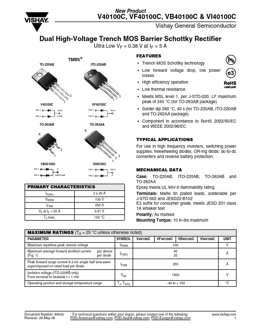
New ProductV40100C, VF40100C, VB40100C & VI40100CVishay General SemiconductorDocument Number: 89042For technical questions within your region, please contact one of the following:Dual High-Voltage Trench MOS Barrier Schottky RectifierUltra Low V F = 0.38 V at I F = 5 AFEATURES•Trench MOS Schottky technology•Low forward voltage drop, low powerlosses•High efficiency operation•Low thermal resistance•Meets MSL level 1, per J-STD-020, LF maximumpeak of 245 °C (for TO-263AB package)•Solder dip 260 °C, 40 s (for TO-220AB, ITO-220ABand TO-262AA package)•Component in accordance to RoHS 2002/95/ECand WEEE 2002/96/ECTYPICAL APPLICATIONSFor use in high frequency inverters, switching powersupplies, freewheeling diodes, OR-ing diode, dc-to-dcconverters and reverse battery protection.MECHANICAL DATACase: TO-220AB, ITO-220AB, TO-263AB andTO-262AAEpoxy meets UL 94V-0 flammability ratingTerminals: Matte tin plated leads, solderable perJ-STD-002 and JESD22-B102E3 suffix for consumer grade, meets JESD 201 class1A whisker testPolarity: As markedMounting Torque:10 in-lbs maximumPRIMARY CHARACTERISTICSI F(AV) 2 x 20 AV RRM100 VI FSM250 AV F at I F = 20 A0.61 VT J max.150 °C12312KMAXIMUM RATINGS (T A = 25°C unless otherwise noted)PA AMETE SYMBOLV40100C VF40100C VB40100C VI40100C UNIT Maximum repetitive peak reverse voltage V RRM 100VMaximum average forward rectified current(Fig. 1)per deviceper diodeI F(AV)4020APeak forward surge current 8.3 ms single half sine-wavesuperimposed on rated load per diodeI FSM 250 AIsolation voltage (ITO-220AB only)From terminal to heatsink t = 1 minV AC1500VOperating junction and storage temperature range T J, T STG- 40 to + 150 °CNew ProductV40100C, VF40100C, VB40100C & VI40100CVishay General Semiconductor For technical questions within your region, please contact one of the following:Document Number: 89042Notes:(1) Pulse test: 300 µs pulse width, 1 % duty cycle (2) Pulse test: Pulse width ≤ 40 msRATINGS AND CHARACTERISTICS CURVES (T A = 25 °C unless otherwise noted)ELECTRICAL CHARACTERISTICS (T A = 25°C unless otherwise noted)PA AMETE TEST CONDITIONS SYMBOL TYP.MAX.UNITBreakdown voltage(2)I R = 1.0 mAT A = 25 °CV BR100 (minimum)-VI R = 10 mA 105 (minimum)-Instantaneous forward voltage per diode (1)I F = 5 AI F = 10 A I F = 20 A T A = 25 °CV F0.470.540.67--0.73VI F = 5 A I F = 10 A I F = 20 A T A = 125 °C 0.380.450.61--0.67Reverse current at rated V R per diode (2)V R = 70 V T A = 25 °C T A = 125 °C I R910--µA mA V R = 100 VT A = 25 °C T A = 125 °C-21100045µA mATHERMAL CHARACTERISTICS (T A = 25°C unless otherwise noted)PA AMETE SYMBOL V40100C VF40100C VB40100CVI40100CUNITTypical thermal resistance per diodeR θJC2.04.02.02.0°C/WORDERING INFORMATION (Example)PACKAGE PREFERRED P/N UNIT WEIGHT (g)PACKAGE CODEBASE QUANTITYDELIVERY MODETO-220AB V40100C-E3/4W 1.854W 50/tube T ube ITO-220AB VF40100C-E3/4W 1.754W 50/tube T ube TO-263AB VB40100C-E3/4W 1.394W 50/tube T ube TO-263AB VB40100C-E3/8W 1.398W 800/reel T ape and reelTO-262AAVI40100C-E3/4W1.464W50/tubeTubeFigure 1. Forward Current Derating Curve Figure 2. Forward Power Loss Characteristics Per DiodeNew ProductV40100C, VF40100C, VB40100C & VI40100CVishay General Semiconductor Document Number: 89042For technical questions within your region, please contact one of the following: Figure3. Typical Instantaneous Forward Characteristics Per DiodeFigure4. Typical Reverse Characteristics Per DiodeFigure5. Typical Junction Capacitance Per DiodeFigure6. Typical Transient Thermal Impedance Per DiodeFigure7. Typical Transient Thermal Impedance Per DiodeNew ProductV40100C, VF40100C, VB40100C & VI40100CVishay General Semiconductor For technical questions within your region, please contact one of the following:Document Number: 89042PACKAGE OUTLINE DIMENSIONS in inches (millimeters)Disclaimer Legal Disclaimer NoticeVishayAll product specifications and data are subject to change without notice.Vishay Intertechnology, Inc., its affiliates, agents, and employees, and all persons acting on its or their behalf (collectively, “Vishay”), disclaim any and all liability for any errors, inaccuracies or incompleteness contained herein or in any other disclosure relating to any product.Vishay disclaims any and all liability arising out of the use or application of any product described herein or of any information provided herein to the maximum extent permitted by law. The product specifications do not expand or otherwise modify Vishay’s terms and conditions of purchase, including but not limited to the warranty expressed therein, which apply to these products.No license, express or implied, by estoppel or otherwise, to any intellectual property rights is granted by this document or by any conduct of Vishay.The products shown herein are not designed for use in medical, life-saving, or life-sustaining applications unless otherwise expressly indicated. Customers using or selling Vishay products not expressly indicated for use in such applications do so entirely at their own risk and agree to fully indemnify Vishay for any damages arising or resulting from such use or sale. Please contact authorized Vishay personnel to obtain written terms and conditions regarding products designed for such applications.Product names and markings noted herein may be trademarks of their respective owners.Document Number: 。
Sun SPARC

Sun SP ARC® EnterpriseM4000/M5000 伺服器產品說明適用於 XCP 版本 1041 Sun Microsystems, Inc.文件號碼 820-2445-102007 年 6 月,修訂版 A請將您對本文件的意見提交至:/hwdocs/feedback請回收Copyright 2007 Sun Microsystems, Inc., 4150 Network Circle, Santa Clara, California 95054, U.S.A. 與 FUJITSU LIMITED, 1-1, Kamikodanaka 4-chome, Nakahara-ku, Kawasaki-shi, Kanagawa-ken 211-8588, Japan 。
版權所有。
Sun Microsystems, Inc. 和 Fujitsu Limited 對於本文件所述之相關產品和技術,分別擁有或控制智慧財產權,而且此類產品、技術和本文件皆受著作權法、專利法、其他智慧財產權法以及國際公約所保護。
在上述的產品、技術和本文件中,Sun Microsystems, Inc. 和 Fujitsu Limited 的智慧財產權包括 /patents 上所列的一項或多項美國專利,以及在美國或其他國家/地區擁有的一項或多項其他專利或專利申請,但並不以此為限。
本文件及相關產品與技術在限制其使用、複製、發行及反編譯的授權下發行。
未經 Fujitsu Limited 、Sun Microsystems, Inc 及其適用授權人 (如果有) 事先的書面許可,不得使用任何方法、任何形式來複製本產品、技術或文件的任何部分。
提供本文件並不表示您享有相關產品或技術的任何明示或暗示性權限或授權,同時本文件不包含或代表 Fujitsu Limited 、Sun Microsystems, Inc. 或任何關係企業的任何承諾。
功能参数简表vF0基本功能

0.OOHz一最大频率
0.01Hz
0.∞Hz
⅛
34H
F2-07
AI2最大输入
0.∞V-10.00V
0.01V
10.OOV
*
35H
F2-08
AI2最大输入对应设定频率
O.OOHz~最大频率
0.01Hz
50.00Hz
*
36H
F2-09
AI2输入谑波时间
0.00s~5.00s
0.01s
F4-11
设定运行时间
0h-65535h
1h
Oh
⅛
62H
F4-12
运行时间到达动作选择
0:继续运行
1:停机
1
1
★
63H
F4-13
频率检测值(FDT电
平)
O.OOHz~最大频率
0.01Hz
50.00Hz
A
64H
F4-14
频率检测FDT滞后值
O.O%~1OO.O%(FDTEII
0.1%
5.0%
*
65H
F4-15
多段速度5
0~最大频率
0.01Hz
20.00Hz
⅛
6EH
F5-06
多段速度6
0~最大频率
0.01Hz
25.00Hz
⅛
6FH
F5-07
多段速度7
0~最大频率
0.01Hz
28.00Hz
⅛
70H
F5-08
多段速度8
0~最大频率
1:启动时运行
1
1
⅛
2BH
F1-17
F1-18
保留
科达4010C串口配置说明

首先用串口线一端连接电脑的串口,一端连接4010C的CON口一、点击,所有程序-附件-通讯-超级终端二、输入超级终端的名称(随便)三、在连接时使用中选择:COM1,并确定四、点击“还原为默认值”并确定五、现在进入了配置模式username:admin //用户名adminpassword:***** //密码adminKEDA#con //进入配置状态KEDA(config)#int e0 //进入以太网配置端口KEDA(config-if-ethernet 0)#ip addr 10.51.174.177 255.255.255.240 //配置设备的IP地址KEDA(config-if-ethernet 0)#int s 0 //进入广域网配置端口(有的版本的设备端口为16,这里为0)KEDA(config-if-serial 0)#ip addr 10.51.177.30 255.255.255.252 //配置设备广域网口的IP地址KEDA(config-if-serial 0)#enc ppp //协议封装方式KEDA(config-if-serial 0)#exit //返回上一级KEDA(config)#ip rout 0.0.0.0 0.0.0.0 10.51.177.29 或ip route 0.0.0.0 0.0.0.0 serial 0 //配置配置默认路由KEDA(config)#end //返回到根目录KEDA#wr //保存配置正在将配置写入闪存,请等待...配置写入成功!KEDA#如果在DOS窗口下可以这样操作Microsoft Windows XP [版本5.1.2600](C) 版权所有1985-2001 Microsoft Corp.C:\Documents and Settings\jnpayoo>telnet 10.51.174.177Choose the record file:0 telnetc_01 telnetc_12 telnetc_23 telnetc_3Choose: Choosed record file:telnetc_0Press <ENTER> to loginusername:adminpassword:*****jinan#一下操作跟直接连电脑就一样了。
神钢C-10VF 取扱说明书(中国)

■ 阅读“使用说明书”后,务必妥善保管,以便使用本产品的人员能够随时阅读。 ■ 使用的产品转让或出借时,务必将“使用说明书”随附于产品本体的醒目位置,以便新的所有者了解安全 正确的使用方法。 ■ 本“安全注意事项”所记载的危险、警告、注意并未涵盖所有情况。请仔细阅读使用说明书,并始终将安 全放在第一位。
2/31
危险
不能用于压电方式的零件供料机。 请勿在放置可燃物、易燃物等危险品的场所使用。 本产品并非防爆型。可能会起火或燃烧。 安装产品时,务必进行可靠夹持和固定。 否则,可能会因产品翻倒、掉落、异常动作等造成人员受伤。 请勿在本产品上淋水。淋水、清洗或在水中使用,均可能会因异常动作造成人员受伤、触电、火灾等。 因配线作业等拆下护罩作业前,应切断输入电源。 外壳内有高电压,非常危险。
昕芙旎雅株式会社
前言
衷心感谢您选用 C10 系列控制器。 为正确使用本控制器,使用前请务必阅读本使用说明书。 本说明书也适用于维护时参阅,请妥善保管。 另外,请将其交给最终用户。
目
录
前言......................................................................................................................................................1 安全注意事项 .......................................................................................................................................2 配线......................................................................................................................................................5 面板基本操作 .......................................................................................................................................7
西门子CC工控

通讯产品 ................................................................................................................................. 3/229
AS-interface ................................................................................................................................. 3/229 ET200 电机起动器 ........................................................................................................................ 3/235 SIMOCODE.................................................................................................................................. 3/237
SIRIUS 继电器产品.......................................................................................................... 3/223
热敏电阻电机保护继电器 3RN ....................................................................... 3/223
MBR40100PT中文资料
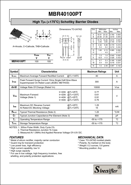
10 0
I n t a t a eu Fr a d r r Fn - I s n no s o w u r C et
T =1 5C 7° J 1 0 T =1 5C 2° J T= 2 ° 5C J
o aa nC ci t ace C p) p n - ( F T
R v ene m e t r I rs ( C - ue
元器件交易网
MBR40100PT
High Tjm (+175oC) Schottky Barrier Diodes
A C(TAB) A C A C A Dimensions TO-247AD
Dim. A B C D E F G H Millimeter Min. Max. 19.81 20.32 20.80 21.46 15.75 16.26 3.55 3.65 4.32 5.4 1.65 1.0 10.8 4.7 0.4 1.5 5.49 6.2 2.13 4.5 1.4 11.0 5.3 0.8 2.49 Inches Min. Max. 0.780 0.819 0.610 0.140 0.170 0.212 0.065 0.040 0.426 0.185 0.016 0.087 0.800 0.845 0.640 0.144 0.216 0.244 0.084 0.177 0.055 0.433 0.209 0.031 0.102
1 8
Rth C(D ) =1 5 C C .2 ° /W J
D=0 8 .0 1 D=0 7 6 .1 D=0 5 .2 1 4 D=0 3 .3 .5 1 D=0 0 2 1 0 M im 8 R SL it 6 4 2 D C
5
1 0
1 5
2 0
V40100C中文资料
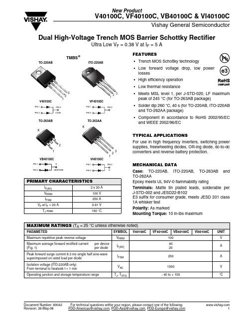
V40100C, VF40100C, VB40100C & VI40100CVishay General SemiconductorDocument Number: 89042For technical questions within your region, please contact one of the following:Dual High-Voltage Trench MOS Barrier Schottky RectifierUltra Low V F = 0.38 V at I F = 5 AFEATURES•Trench MOS Schottky technology •Low forward voltage drop, low power losses •High efficiency operation •Low thermal resistance•Meets MSL level 1, per J-STD-020, LF maximum peak of 245 °C (for TO-263AB package) •Solder dip 260 °C, 40 s (for TO-220AB, ITO-220AB and TO-262AA package) •Component in accordance to RoHS 2002/95/EC and WEEE 2002/96/EC TYPICAL APPLICATIONSFor use in high frequency inverters, switching power supplies, freewheeling diodes, OR-ing diode, dc-to-dc converters and reverse battery protection.MECHANICAL DATACase: TO-220AB, ITO-220AB, TO-263AB and TO-262AAEpoxy meets UL 94V-0 flammability ratingTerminals: Matte tin plated leads, solderable per J-STD-002 and JESD22-B102E3 suffix for consumer grade, meets JESD 201 class 1A whisker testPolarity: As markedMounting Torque:10 in-lbs maximumPRIMARY CHARACTERISTICSI F(AV) 2 x 20 A V RRM 100 V I FSM 250 A V F at I F = 20 A 0.61 V T J max.150 °C12312KMAXIMUM RATINGS (T A = 25°C unless otherwise noted)PA AMETE SYMBOL V40100C VF40100C VB40100C VI40100C UNITMaximum repetitive peak reverse voltage V RRM 100V Maximum average forward rectified current (Fig. 1)per device per diodeI F(AV)4020APeak forward surge current 8.3 ms single half sine-wave superimposed on rated load per diode I FSM 250 A Isolation voltage (ITO-220AB only)From terminal to heatsink t = 1 minV AC 1500V Operating junction and storage temperature rangeT J , T STG- 40 to + 150°CV40100C, VF40100C, VB40100C & VI40100CVishay General Semiconductor For technical questions within your region, please contact one of the following:Document Number: 89042Notes:(1) Pulse test: 300 µs pulse width, 1 % duty cycle (2) Pulse test: Pulse width ≤ 40 msRATINGS AND CHARACTERISTICS CURVES (T A = 25 °C unless otherwise noted)ELECTRICAL CHARACTERISTICS (T A = 25°C unless otherwise noted)PA AMETE TEST CONDITIONS SYMBOL TYP.MAX.UNITBreakdown voltage(2)I R = 1.0 mAT A = 25 °CV BR100 (minimum)-VI R = 10 mA 105 (minimum)-Instantaneous forward voltage per diode (1)I F = 5 AI F = 10 A I F = 20 A T A = 25 °CV F0.470.540.67--0.73VI F = 5 A I F = 10 A I F = 20 A T A = 125 °C 0.380.450.61--0.67Reverse current at rated V R per diode (2)V R = 70 V T A = 25 °C T A = 125 °C I R910--µA mA V R = 100 VT A = 25 °C T A = 125 °C-21100045µA mATHERMAL CHARACTERISTICS (T A = 25°C unless otherwise noted)PA AMETE SYMBOL V40100C VF40100C VB40100CVI40100CUNITTypical thermal resistance per diodeR θJC2.04.02.02.0°C/WORDERING INFORMATION (Example)PACKAGE PREFERRED P/N UNIT WEIGHT (g)PACKAGE CODEBASE QUANTITYDELIVERY MODETO-220AB V40100C-E3/4W 1.854W 50/tube T ube ITO-220AB VF40100C-E3/4W 1.754W 50/tube T ube TO-263AB VB40100C-E3/4W 1.394W 50/tube T ube TO-263AB VB40100C-E3/8W 1.398W 800/reel T ape and reelTO-262AAVI40100C-E3/4W1.464W50/tubeTubeFigure 1. Forward Current Derating Curve Figure 2. Forward Power Loss Characteristics Per DiodeV40100C, VF40100C, VB40100C & VI40100CVishay General SemiconductorDocument Number: 89042For technical questions within your region, please contact one of the following:Figure 3. Typical Instantaneous Forward Characteristics Per Diode Figure 4. Typical Reverse Characteristics Per Diode Figure 5. Typical Junction Capacitance Per DiodeFigure 6. Typical Transient Thermal Impedance Per DiodeFigure7. Typical Transient Thermal Impedance Per DiodeV40100C, VF40100C, VB40100C & VI40100CVishay General Semiconductor For technical questions within your region, please contact one of the following:Document Number: 89042PACKAGE OUTLINE DIMENSIONS in inches (millimeters)Disclaimer Legal Disclaimer NoticeVishayAll product specifications and data are subject to change without notice.Vishay Intertechnology, Inc., its affiliates, agents, and employees, and all persons acting on its or their behalf (collectively, “Vishay”), disclaim any and all liability for any errors, inaccuracies or incompleteness contained herein or in any other disclosure relating to any product.Vishay disclaims any and all liability arising out of the use or application of any product described herein or of any information provided herein to the maximum extent permitted by law. The product specifications do not expand or otherwise modify Vishay’s terms and conditions of purchase, including but not limited to the warranty expressed therein, which apply to these products.No license, express or implied, by estoppel or otherwise, to any intellectual property rights is granted by this document or by any conduct of Vishay.The products shown herein are not designed for use in medical, life-saving, or life-sustaining applications unless otherwise expressly indicated. Customers using or selling Vishay products not expressly indicated for use in such applications do so entirely at their own risk and agree to fully indemnify Vishay for any damages arising or resulting from such use or sale. Please contact authorized Vishay personnel to obtain written terms and conditions regarding products designed for such applications.Product names and markings noted herein may be trademarks of their respective owners.元器件交易网Document Number: 。
VCNL4010-GS08;中文规格书,Datasheet资料

Fully Integrated Proximity and Ambient Light Sensor with Infrared Emitter, I 2C Interface, and Interrupt FunctionDESCRIPTIONThe VCNL4010 is a fully integrated proximity and ambient light sensor. Fully integrated means that the infrared emitter is included in the package. It has 16 bit resolution. It includes a signal processing IC and features standard I 2C communication interface. It features an interrupt function.APPLICATIONS•Proximity sensor for mobile devices (e.g. smart phones,touch phones, PDA, GPS) for touch screen locking, power saving, etc.•Integrated ambient light function for display/keypad contrast control and dimming of mobile devices•Proximity/optical switch for consumer, computing and industrial devices and displays•Dimming control for consumer, computing and industrial displaysFEATURES•Package type: surface mount•Dimensions (L x W x H in mm): 3.95 x 3.95 x 0.75•Integrated infrared emitter, ambient light sensor,proximity sensor, and signal conditioning IC •Interrupt function•Supply voltage range V DD : 2.5 V to 3.6 V •Supply voltage range IR anode: 2.5 V to 5 V •Communication via I 2C interface •I 2C Bus H-level range: 1.7 V to 5 V •Floor life: 168 h, MSL 3, acc. J-STD-020•Low stand by current consumption: 1.5 μA•ompliant to RoHS Directive 2011/65/EU and in accordance to WEEE 2002/96/ECNote**Please see document “Vishay Material Category Policy”:/doc?99902PROXIMITY FUNCTION•Built-in infrared emitter and photo-pin-diode for proximity function•16 bit effective resolution for proximity detection range ensures excellent cross talk immunity•Programmable LED drive current from 10 mA to 200 mA in 10 mA steps•Excellent ambient light suppression by modulating the infrared signal•Proximity distance up to 200 mmAMBIENT LIGHT FUNCTION•Built-in ambient light photo-pin-diode with close-to-human-eye sensitivity•16 bit dynamic range from 0.25 lx to 16 klx •100 Hz and 120 Hz flicker noise rejectionNote(1)Adjustable through I 2C interfacePRODUCT SUMMARYPART NUMBER OPERATING RANGE (mm)OPERATING VOLTAGE RANGE (V)I 2C BUS VOLTAGE RANGE (V)LED PULSE CURRENT (1)(mA)AMBIENT LIGHT RANGE (lx)AMBIENT LIGHT RESOLUTION(lx)OUTPUT CODE VCNL40101 to 2002.5 to3.61.7 to 510 to 2000.25 to 16 3830.2516 bit, I 2CNotes(1)MOQ: minimum order quantity(2)VCNL4000 Demokit provides USB dongle, basic software including Vishay licence. The VCNL4010 sensor board could be ordered free of charge by contacting sensorstechsupport@ . Software updates for VC NL4010 can be downloaded from our web site:/???/ORDERING INFORMATIONORDERING CODE PACKAGING VOLUME (1)REMARKSVCNL4010-GS08Tape and reelMOQ: 1800 pcs 3.95 mm x 3.95 mm x 0.75 mmVCNL4010-GS18MOQ: 7000 pcsVCNL4000Demokit (2)-MOQ: 1 pc-ABSOLUTE MAXIMUM RATINGS (T amb = 25 °C, unless otherwise specified)PARAMETER TEST CONDITIONSYMBOL MIN.MAX.UNIT Supply voltageV DD - 0.3 5.5V Operation temperature range T amb - 25+ 85°C Storage temperature range T stg - 40+ 85°C Total power dissipation T amb ≤ 25 °C P tot 50mW Junction temperatureT j100°CBASIC CHARACTERISTICS (T amb = 25 °C, unless otherwise specified)PARAMETER TEST CONDITIONSYMBOLMIN.TYP.MAX.UNIT Supply voltage V DD 2.5 3.6V Supply voltage IR anode 2.55V I 2C Bus H-level range 1.75V INT H-level range 1.75V INT low voltage 3 mA sink current 0.4V Current consumptionStandby current,no IRED-operation 1.52μA Current consumptionproximity mode incl. IRED (averaged)2 measurements per second,IRED current 20 mA5μA 250 measurements per second,IRED current 20 mA 520μA 2 measurements per second,IRED current 200 mA 35μA 250 measurements per second,IRED current 200 mA 4.0mA Current consumption ambient light mode2 measurements per secondaveraging = 12.5μA 8 measurements per secondaveraging = 110μA 2 measurements per secondaveraging = 64160μA 8 measurements per secondaveraging = 64640μA Ambient light resolution Digital resolution (LSB count )0.25lx Ambient light output E V = 100 lx averaging = 64400counts I 2C clock rate rangef SCL3400kHzCIRCUIT BLOCK DIAGRAMNote•nc must not be electrically connectedPads 8 to 11 are only considered as solder padsTEST CIRCUIT BASIC CHARACTERISTICS (T amb = 25 °C, unless otherwise specified)Fig. 1 - Idle Current vs. Ambient Temperature Fig. 2 - Idle Current vs. V DDFig. 3 - Proximity Value vs. Distance Fig. 4 - Forward Current vs. TemperatureFig. 5 - Relative Radiant Intensity vs. WavelengthFig. 6 - Relative Radiant Intensity vs. Angular Displacement Fig. 7 - Relative Spectral Sensitivity vs. Wavelength(Proximity Sensor) Fig. 8 - Relative Radiant Sensitivity vs. Angular Displacement(Proximity Sensor)Fig. 9 - Ambient Light Value vs. Illuminance Fig. 10 - Relative Spectral Sensitivity vs. Wavelength(Ambient Light Sensor)Fig. 11 - Relative Radiant Sensitivity vs. Angular Displacement(Ambient Light Sensor)APPLICATION INFORMATIONVCNL4010 is a cost effective solution of proximity and ambient light sensor with I2C bus interface. The standard serial digital interface is easy to access “Proximity Signal” and “Light Intensity” without complex calculation and programming by external controller. Beside the digital output also a flexible programmable interrupt pin is available.1. Application CircuitFig. 12 - Application Circuit(x) = Pin NumberNote•The interrupt pin is an open drain output. The needed pull-up resistor may be connected to the same supply voltage as the application controller and the pull-up resistors at SDA/SCL. Proposed value R2 should be >1 kΩ , e.g. 10 kΩ to 100 kΩ.Proposed value for R3 and R4, e.g. 2.2 kΩ to 4.7 kΩ, depend also on the I2C bus speed.For detailed description about set-up and use of the interrupt as well as more application related information see AN: “Designing VCNL4010 into an Application”.2. I 2C InterfaceThe VCNL4010 contains seventeen 8 bit registers for operation control, parameter setup and result buffering. All registers are accessible via I 2C communication. Figure 13 shows the basic I 2C communication with VCNL4010.The built in I 2C interface is compatible with all I 2C modes (standard, fast and high speed).I 2C H-level range = 1.7 V to 5 V.Please refer to the I 2C specification from NXP for details.Device AddressThe VC NL4010 has a fix slave address for the host programming and accessing selection. The predefined 7 bit I 2C bus address is set to 0010 011 = 13h. The least significant bit (LSB) defines read or write mode. Accordingly the bus address is set to 0010 011x = 26h for write, 27h for read.Register AddressesVC NL4010 has seventeen user accessible 8 bit registers.The register addresses are 80h (register #0) to 90h (register #16).REGISTER FUNCTIONSRegister #0 Command RegisterRegister address = 80hThe register #0 is for starting ambient light or proximity measurements. This register contains 2 flag bits for data ready indication.Note•With setting bit 3 and bit 4 at the same write command, a simultaneously measurement of ambient light and proximity is done. Beside als_en and/or prox_en first selftimed_en needs to be set. On-demand measurement modes are disabled if selftimed_en bit is set. For the selftimed_en mode changes in reading rates (reg #4 and reg #2) can be made only when b0 (selftimed_en bit) = 0. For the als_od mode changes to the reg #4 can be made only when b4 (als_od bit) = 0; this is to avoid synchronization problems and undefined states between the clock domains. In effect this means that it is only reasonable to change rates while no selftimed conversion is ongoing.TABLE 1 - COMMAND REGISTER #0Bit 7Bit 6Bit 5Bit 4Bit 3Bit 2Bit 1Bit 0config_lockals_data_rdyprox_data_rdyals_odprox_odals_enprox_enselftimed_enDescriptionconfig_lock Read only bit. Value = 1als_data_rdy Read only bit. Value = 1 when ambient light measurement data is available in the result registers. This bitwill be reset when one of the corresponding result registers (reg #5, reg #6) is read.prox_data_rdyRead only bit. Value = 1 when proximity measurement data is available in the result registers. This bit will be reset when one of the corresponding result registers (reg #7, reg #8) is read.als_od R/W bit. Starts a single on-demand measurement for ambient light. If averaging is enabled, starts a sequence of readings and stores the averaged result. Result is available at the end of conversion for reading in the registers #5(HB) and #6(LB).prox_od R/W bit. Starts a single on-demand measurement for proximity.Result is available at the end of conversion for reading in the registers #7(HB) and #8(LB).als_en R/W bit. Enables periodic als measurement prox_en R/W bit. Enables periodic proximity measurementselftimed_enR/W bit. Enables state machine and LP oscillator for self timed measurements; no measurement is performed until the corresponding bit is setRegister #1 Product ID Revision RegisterRegister address = 81h. This register contains information about product ID and product revision.Register data value of current revision = 21h.Register #2 Rate of Proximity Measurement Register address = 82h.Note•If self_timed measurement is running, any new value written in this register will not be taken over until the mode is actualy cycled.Register #3 LED Current Setting for Proximity ModeRegister address = 83h. This register is to set the LED current value for proximity measurement.The value is adjustable in steps of 10 mA from 0 mA to 200 mA.This register also contains information about the used device fuse program ID.TABLE 2 - PRODUCT ID REVISION REGISTER #1Bit 7Bit 6Bit 5Bit 4Bit 3Bit 2Bit 1Bit 0Product IDRevision IDDescriptionProduct ID Read only bits. Value = 2Revision IDRead only bits. Value = 1TABLE 3 - PROXIMITY RATE REGISTER #2Bit 7Bit 6Bit 5Bit 4Bit 3Bit 2Bit 1Bit 0n/aRate of Proximity Measurement (no. ofmeasurements per second)DescriptionProximity rateR/W bits.000 - 1.95 measurements/s (DEFAULT)001 - 3.90625 measurements/s 010 - 7.8125 measurements/s 011 - 16.625 measurements/s 100 - 31.25 measurements/s 101 - 62.5 measurements/s 110 - 125 measurements/s 111 - 250 measurements/sTABLE 4 - IR LED CURRENT REGISTER #3Bit 7Bit 6Bit 5Bit 4Bit 3Bit 2Bit 1Bit 0Fuse prog IDIR LED current valueDescriptionFuse prog ID Read only bits.Information about fuse program revision used for initial setup/calibration of the device.IR LED current valueR/W bits. IR LED current = Value (dec.) x 10 mA.Valid Range = 0 to 20d. e.g. 0 = 0 mA , 1 = 10 mA, …., 20 = 200 mA (2 = 20 mA = DEFAULT) LED Current is limited to 200 mA for values higher as 20d.Register #4 Ambient Light Parameter Register Register address = 84h.Note•If self_timed measurement is running, any new value written in this register will not be taken over until the mode is actualy cycled.Register #5 and #6 Ambient Light Result RegisterRegister address = 85h and 86h. These registers are the result registers for ambient light measurement readings.The result is a 16 bit value. The high byte is stored in register #5 and the low byte in register #6.TABLE 5 - AMBIENT LIGHT PARAMETER REGISTER #4Bit 7Bit 6Bit 5Bit 4Bit 3Bit 2Bit 1Bit 0Cont. conv.modeals_rateAuto offset compensationAveraging function(number of measurements per run)DescriptionCont. conversion modeR/W bit. Continuous conversion mode.Enable = 1; Disable = 0 = DEFAULTThis function can be used for performing faster ambient light measurements. Please refer to the application information chapter 3.3 for details about this function. Ambient light measurement rateR/W bits. Ambient light measurement rate 000 - 1 samples/s001 - 2 samples/s = DEFAULT 010 - 3 samples/s 011 - 4 samples/s 100 - 5 samples/s 101 - 6 samples/s 110 - 8 samples/s 111 - 10 samples/sAuto offset compensationR/W bit. Automatic offset compensation.Enable = 1 = DEFAULT; Disable = 0In order to compensate a technology, package or temperature related drift of the ambient light values there is a built in automatic offset compensation function.With active auto offset compensation the offset value is measured before each ambient light measurement and subtracted automatically from actual reading.Averaging functionR/W bits. Averaging function.Bit values sets the number of single conversions done during one measurement cycle. Result is the average value of all conversions.Number of conversions = 2decimal_value e.g. 0 = 1 conv., 1 = 2 conv, 2 = 4 conv., ….7 = 128 conv.DEFAULT = 32 conv. (bit 2 to bit 0: 101)TABLE 6 - AMBIENT LIGHT RESULT REGISTER #5Bit 7Bit 6Bit 5Bit 4Bit 3Bit 2Bit 1Bit 0DescriptionRead only bits. High byte (15:8) of ambient light measurement resultTABLE 7 - AMBIENT LIGHT RESULT REGISTER #6Bit 7Bit 6Bit 5Bit 4Bit 3Bit 2Bit 1Bit 0DescriptionRead only bits. Low byte (7:0) of ambient light measurement resultRegister #7 and #8 Proximity Measurement Result RegisterRegister address = 87h and 88h. These registers are the result registers for proximity measurement readings.The result is a 16 bit value. The high byte is stored in register #7 and the low byte in register #8.Register #9 Interrupt Control Register Register address = 89h.TABLE 8 - PROXIMITY RESULT REGISTER #7Bit 7Bit 6Bit 5Bit 4Bit 3Bit 2Bit 1Bit 0DescriptionRead only bits. High byte (15:8) of proximity measurement resultTABLE 9 - PROXIMITY RESULT REGISTER #8Bit 7Bit 6Bit 5Bit 4Bit 3Bit 2Bit 1Bit 0DescriptionRead only bits. Low byte (7:0) of proximity measurement resultTABLE 10 - INTERRUPT CONTROL REGISTER #9Bit 7Bit 6Bit 5Bit 4Bit 3Bit 2Bit 1Bit 0Int count exceedn/aINT_PROX_ready_ENINT_ALS_ready_ENINT_THRES_ENINT_THRES_SELDescriptionInt count exceedR/W bits. These bits contain the number of consecutive measurements needed above/below the threshold000 - 1 count = DEFAULT 001 - 2 count 010 - 4 count 011 - 8 count 100 -16 count 101 - 32 count 110 - 64 count 111 - 128 countINT_PROX_ready_EN R/W bit. Enables interrupt generation at proximity data ready INT_ALS_ ready_EN R/W bit. Enables interrupt generation at ambient data readyINT_THRES_EN R/W bit. Enables interrupt generation when high or low threshold is exceeded INT_THRES_SELR/W bit. If 0: thresholds are applied to proximity measurements If 1: thresholds are applied to als measurementsRegister #10 and #11 Low ThresholdRegister address = 8Ah and 8Bh. These registers contain the low threshold value. The value is a 16 bit word. The high byte is stored in register #10 and the low byte in register #11.TABLE 11 - LOW THRESHOLD REGISTER #10Bit7Bit6Bit5Bit4Bit3Bit2Bit1Bit0DescriptionR/W bits. High byte (15:8) of low threshold valueTABLE 12 - LOW THRESHOLD REGISTER #11Bit7Bit6Bit5Bit4Bit3Bit2Bit1Bit0DescriptionR/W bits. Low byte (7:0) of low threshold valueRegister #12 and #13 High ThresholdRegister address = 8Ch and 8Dh. These registers contain the high threshold value. The value is a 16 bit word. The high byte is stored in register #12 and the low byte in register #13.TABLE 13 - HIGH THRESHOLD REGISTER #12Bit7Bit6Bit5Bit4Bit3Bit2Bit1Bit0DescriptionR/W bits. High byte (15:8) of high threshold valueTABLE 14 - HIGH THRESHOLD REGISTER #13Bit7Bit6Bit5Bit4Bit3Bit2Bit1Bit0DescriptionR/W bits. Low byte (7:0) of high threshold valueRegister #14 Interrupt Status RegisterRegister address = 8Eh. This register contains information about the interrupt status for either proximity or ALS function and indicates if high or low going threshold exceeded.TABLE 15 - INTERRUPT STATUS REGISTER #14Bit7Bit6Bit5Bit4Bit3Bit2Bit1Bit0n/a int_prox_ready int_als_ready int_th_low int_th_hiDescriptionint_prox_ready R/W bit. Indicates a generated interrupt for proximityint_als_ready R/W bit. Indicates a generated interrupt for alsint_th_low R/W bit. Indicates a low threshold exceedint_th_hi R/W bit. Indicates a high threshold exceedNote•Once an interrupt is generated the corresponding status bit goes to 1 and stays there unless it is cleared by writing a 1 in the corresponding bit. The int pad will be pulled down while at least one of the status bit is 1.分销商库存信息: VISHAYVCNL4010-GS08。
550C中文资料
550C中文资料关键信息项:1、资料名称:550C 中文资料2、资料用途:____________________________3、资料提供方:____________________________4、资料接收方:____________________________5、资料使用期限:____________________________6、资料保密要求:____________________________7、违约责任:____________________________8、争议解决方式:____________________________11 协议背景本协议旨在规范550C 中文资料的相关事宜,确保资料的合理使用、保护和传播。
111 资料的定义和范围本协议中所提及的550C 中文资料包括但不限于文字、图表、图像、音频、视频等与 550C 相关的各类中文形式的信息。
112 资料的用途资料接收方应仅将 550C 中文资料用于具体合法且明确的用途,不得用于其他任何未经授权的目的。
12 资料提供方的权利和义务121 提供方应确保所提供的 550C 中文资料的真实性、准确性和完整性。
122 提供方有权对资料接收方的使用情况进行监督和检查。
13 资料接收方的权利和义务131 接收方应按照协议约定的用途使用 550C 中文资料。
132 接收方有义务对资料进行妥善保管,采取合理的安全措施防止资料泄露、丢失或损坏。
133 未经提供方书面同意,接收方不得将资料转让、出售、出租或提供给任何第三方。
14 资料使用期限141 双方约定 550C 中文资料的使用期限为具体时间段。
142 在使用期限届满后,接收方应立即停止使用并按照提供方的要求归还或销毁资料。
15 资料保密要求151 接收方应对 550C 中文资料予以保密,不得向任何无关人员透露资料的内容。
152 接收方应采取必要的保密措施,如限制访问、加密存储等,以确保资料的保密性。
MCP41050中文

ppm/°C 编码 80h
, RS 和 SHDN 引脚的工作方式请参见图 2-12 数字输入 / 输出 (CS、 SCK、 SI 和 SO)
VAB = VDD,抽头上无连接。 变阻器位置非线性度 R-INL 是指抽头在最大电阻和最小电阻范围内测量的实际位置偏离理想位置的程度。 R-DNL 测量连续抽头位置 间的步长相对理想值的变化。对于 10 kΩ 的电位器, VDD = 3V 时 IW = 50 µA, VDD = 5V 时 IW = 400 µA。测试电路请参见图 2-26。 在器件配置为分压器或电位器模式时,在 VW 上测量 INL 和 DNL。 VA = VDD 且 VB = 0V。 DNL 规范极限值 ±1 LSB (最大值)是在规 定的单调操作条件下的值。测试电路请参见图 2-25。 电阻端子 A、 B 和 W 相互间无极性限制。满量程误差和零刻度误差使用图 2-25 进行测量。 在 VW 引脚上测得,此时该引脚附近的另一个 VW 引脚上的电压满幅摆动。 供电电流与流经电位器的电流无关。
2006 Microchip Technology Inc.
DS11195C_CN 第 1 页
MCP41XXX/42XXX
1.0 电气特性 直流特性:10 kΩ 器件
电气特性:除非另外声明,否则 VDD = +2.7V 至 5.5V 且 TA = -40°C 至 +85°C (TSSOP 器件只能在 +25°C 和 +85°C 条件下工作) 。 典型规范值:VDD = 5V、 VSS = 0V、 VB = 0V 且 TA = +25°C。 参数 变阻器模式 标称电阻 变阻器差分非线性度 变阻器积分非线性度 变阻器温度系数 抽头电阻 抽头电流 标称电阻匹配 电位器分压器 分辨率 单调性 差分非线性度 积分非线性度 分压器温度系数 满量程误差 零刻度误差 电阻端子 电压范围 电容 (CA 或 CB) 电容 带宽 -3dB 稳定时间 电阻噪声电压 串扰 施密特触发器高电平输入电压 施密特触发器低电平输入电压 施密特触发器输入迟滞 低输出电压 高输出电压 输入泄漏电流 引脚电容 (所有输入 / 输出) 电源要求 工作电压范围 输入电流,有源 输入电流,静态 电源灵敏度 注 1: 2: 3: 4: 5: 6: VDD IDDA IDDS PSS PSS 2.7 - - - - - 340 0.01 0.0015 0.0015 5.5 500 1 0.0035 0.0035 V µA µA %/% %/% VDD = 5.5V, CS = VSS, fSCK = 10 MHz, SO = 开路,编码 FFh (注 6) CS, SHDN, RS = VDD = 5.5V, SO = 开路 (注 6) VDD = 4.5V - 5.5V, VA = 4.5V,编码 80h VDD = 2.7V -3.3V, VA = 2.7V,编码 80h CW BW tS eNWB CT VIH VIL VHYS VOL VOH ILI CIN 和 COUT 动态特性 (测试所有动态特性时 VDD = 5V) - - - - 0.7VDD - - - VDD - 0.5 -1 - 1 2 9 -95 - - .05VDD - - - 10 - - - - - .3VDD - 0.40 - +1 - V V µA pF IOL = 2.1 mA, VDD = 5V IOH = -400 µA, VDD = 5V CS = VDD, VIN = VSS 或 VDD,包括 VA SHDN=0 VDD = 5.0V, TA = +25°C, fc = 1 MHz MHz µS nV/√Hz dB V V VB = 0V,在编码为 80h,输出负载 = 30 PF 时测得 VA = VDD, VB = 0V,误差范围为 ±1%,编码从 00h 过 渡到 80h,输出负载 = 30 pF VA = 开路,编码 80h, f = 1 kHz VA = VDD, VB = 0V (注 5) VA,B,W 0 - - - 15 5.6 VDD - - pF pF 注4 f = 1 MHz,编码 80h,请参见图 2-30 f = 1 MHz,编码 80h,请参见图 2-30 N N DNL INL ∆VW/∆T VWFSE VWFSE VWZSE VWZSE 8 8 -1 -1 - -2 -2 0 0 - - ±1/4 ±1/4 1 -0.7 -0.7 +0.7 +0.7 - - +1 +1 - 0 0 +2 +2 位 位 LSB LSB LSB LSB LSB LSB 注3 注3 编码 FFh, VDD = 5V,请参见图 2-25 编码 FFh, VDD = 3V,请参见图 2-25 编码 00h, VDD = 5V,请参见图 2-25 编码 00h, VDD = 3V,请参见图 2-25 R R-DNL R-INL ∆RAB/∆T RW RW IW ∆R/R 8 -1 -1 - - - -1 - 10 ±1/4 ±1/4 800 52 73 - 0.2 12 +1 +1 - 100 125 +1 1 kΩ LSB LSB ppm/°C Ω Ω mA % 仅 MCP42010, P0 到 P1 ; TA = +25°C VDD = 5.5V、 IW = 1 mA、编码 00h VDD = 2.7V、 IW = 1 mA、编码 00h TA = +25°C (注 1) 注2 注2 符号 最小值 典型值 最大值 单位 条件
SI4010中文手册

SI4010-C2数据手册-中文特点⏹ 可配置不使用外部晶振➢ 晶振源可配置 ⏹ 高速8051UC 内核 ➢管道指令架构 ➢ 70%的指令执行需要1个或2个时钟周期 ➢ 高达24 MIPs(使用24M 时钟时) ➢ 4k RAM/8k NVM(一次性非易失性存储器) ➢128 bit EEPROM ➢256字节的内部数据RAM ➢ 12 kB API 函数(嵌入在ROM 中) ⏹ 大量的数字外设 ➢ 128位AES 加速器 ➢5/9个具有唤醒功能GPIO ➢LED 驱动器 ➢数据串行器 ➢高速频率计数器 ➢在线调试接口:C2 ➢唯一的4字节序列号 ➢ 超低功耗睡眠定时器 ⏹ 一枚纽扣电池➢ 供给电压:1.8到3.6V ➢ 待机电流 < 10nA ⏹ 高性能射频发射机 ➢ 频率范围:27-960 MHz ➢ +10 dBm 输出功率(可调的) ➢ 天线自动调整 ➢ 符号速率高达100kbps ➢ FSK/OOK 调制方式 ➢ Manchester, NRZ, 4/5编码 ⏹ 模拟外设 ➢带POR 电路的LDO 调节器 ➢ 电池电压监测 ⏹ 温度范围-40至+85℃ ⏹ 可选汽车质量标准AEC-Q100(等待最后的资格测试) ⏹ 10-pin MSOP / 14-pinSOIC说明Si4010是一个全集成无晶体CMOS SoC射频发射机,内置CIP-518051单片机。
该设备可以在-40至85°C的温度范围内运行,而无需外部晶体参考源,从而减少板面积和BOM成本。
该设备包括用于编程用户应用程序的8kb非易失性存储器块以及可以被用户应用程序调用API函数的12k内嵌ROM(存放API函数代码)。
Si4010包括Silicon Laboratories的2线C2调试和编程接口,允许客户在开发阶段将其代码下载到芯片RAM中,以便在对NVM编程之前进行测试和调试。
NVM为一次性烧录,程序开发完毕之后使用NVM烧录最后的应用程序。
北大青鸟

2.检查连接电缆
二
无主电时开备电,控制器无显示。
1.控制器要求必须先开主电再开备电。
1.正常现象,先开主电。
三
报警时无声响
1.喇叭端子接触不良
1.重插接线端子
四
键盘不能操作
1.键盘连接线没有插好
1.插上键盘线
五
开机后显示“主电故障”
1.无AC220V电源
2.主电保险管烧断
1.检查并接好电线
图5.1 控制器多线控制单元面板图
现场没有接联动切换模块的联动区应将其屏蔽,屏蔽方法如下:
1)按下功能键,进入“设置”菜单“登记与屏蔽”项;
2)选择“多线登记”;
3)通过设置,登记和屏蔽5路多线输出,“1=登记,0=屏蔽”;
4)设置完毕后,按“取消”键退出菜单。
控制器多线控制盘箱内端子接线如图6.2:SL1~SL5分别接5个专线控制设备。
多个火警时自动循环显示,按“↓”键可手动查询。
3.
故障指示灯亮,报救护车声的故障声响;
屏幕显示故障信息、报警地址、故障总数,下图屏幕显示故障总数为2个,报警地址分别是001地址故障和011地址故障,同时显示该地址所对应的中文注释信息;两个故障信息循环显示,按“↓”键可手动查询。故障报警自动恢复,所有故障消除后,报警声响消失,报警显示消失,屏幕恢复正常运行状态。
图4.34编程菜单
图4.35输入部位和时间
图4.36输入表达式
4.7
图4.37 启动总线模块
图4.38 输入模块地址
4.8
图4.39 声光启动
第
JB-QB-21S-VFC3010火灾报警控制器(报警型)可控制5路多线输出,每路需配接1只专线控制模块。不接专线控制模块时控制器报故障,表明专线控制模块不在线。多线控制单元面板如图5.1:
fhf40100二极管参数

fhf40100二极管参数fhf40100是一种二极管,它具有特定的参数和特性。
在本文中,我将详细介绍fhf40100二极管的参数,并解释其在电子电路中的应用。
fhf40100二极管是一种高压整流二极管,其主要参数包括最大反向电压、最大正向电流、正向压降和反向恢复时间。
fhf40100的最大反向电压为1000V。
这意味着当二极管处于反向偏置时,其正向电压不得超过1000V,否则会导致二极管击穿或损坏。
fhf40100的最大正向电流为40A。
这表示当二极管处于正向偏置时,其正向电流不得超过40A,否则会导致二极管过载和过热。
fhf40100的正向压降为1.1V。
这意味着当二极管处于正向偏置时,其正向电压降低大约为1.1V。
这个参数对于电路设计和功耗计算非常重要。
fhf40100的反向恢复时间为75ns。
这是指当二极管从正向偏置变为反向偏置时,需要75ns来恢复到正常工作状态。
这个参数在高频电路和开关电源中特别重要。
fhf40100二极管的这些参数使其在电子电路中具有广泛的应用。
它常用于高压整流电路、电源管理和功率转换等领域。
在高压整流电路中,fhf40100可以将交流电转换为直流电,用于电池充电、电源稳定等应用。
其高反向电压和正向电流特性使其能够承受较大的功率和电流负载。
在电源管理中,fhf40100可以用作反向保护二极管,防止电源电压的反向流入电路。
其快速反向恢复时间可以确保电路在反向切换时的稳定性和可靠性。
在功率转换中,fhf40100常用于开关电源和逆变器中。
其低正向压降和高正向电流特性使其能够有效地转换电能,并减少能量损耗。
值得注意的是,在实际应用中,除了fhf40100的参数外,还需要考虑其他因素,如温度特性、封装类型和可靠性等。
fhf40100二极管是一种具有特定参数和特性的高压整流二极管。
它在电子电路中有着广泛的应用,如高压整流电路、电源管理和功率转换等。
了解和理解fhf40100的参数对于正确选择和应用这种二极管至关重要,可以确保电路的稳定性和可靠性。
- 1、下载文档前请自行甄别文档内容的完整性,平台不提供额外的编辑、内容补充、找答案等附加服务。
- 2、"仅部分预览"的文档,不可在线预览部分如存在完整性等问题,可反馈申请退款(可完整预览的文档不适用该条件!)。
- 3、如文档侵犯您的权益,请联系客服反馈,我们会尽快为您处理(人工客服工作时间:9:00-18:30)。
V40100C, VF40100C, VB40100C & VI40100CVishay General SemiconductorDocument Number: 89042For technical questions within your region, please contact one of the following:Dual High-Voltage Trench MOS Barrier Schottky RectifierUltra Low V F = 0.38 V at I F = 5 AFEATURES•Trench MOS Schottky technology •Low forward voltage drop, low power losses •High efficiency operation •Low thermal resistance•Meets MSL level 1, per J-STD-020, LF maximum peak of 245 °C (for TO-263AB package) •Solder dip 260 °C, 40 s (for TO-220AB, ITO-220AB and TO-262AA package) •Component in accordance to RoHS 2002/95/EC and WEEE 2002/96/EC TYPICAL APPLICATIONSFor use in high frequency inverters, switching power supplies, freewheeling diodes, OR-ing diode, dc-to-dc converters and reverse battery protection.MECHANICAL DATACase: TO-220AB, ITO-220AB, TO-263AB and TO-262AAEpoxy meets UL 94V-0 flammability ratingTerminals: Matte tin plated leads, solderable per J-STD-002 and JESD22-B102E3 suffix for consumer grade, meets JESD 201 class 1A whisker testPolarity: As markedMounting Torque:10 in-lbs maximumPRIMARY CHARACTERISTICSI F(AV) 2 x 20 A V RRM 100 V I FSM 250 A V F at I F = 20 A 0.61 V T J max.150 °C12312KMAXIMUM RATINGS (T A = 25°C unless otherwise noted)PA AMETE SYMBOL V40100C VF40100C VB40100C VI40100C UNITMaximum repetitive peak reverse voltage V RRM 100V Maximum average forward rectified current (Fig. 1)per device per diodeI F(AV)4020APeak forward surge current 8.3 ms single half sine-wave superimposed on rated load per diode I FSM 250 A Isolation voltage (ITO-220AB only)From terminal to heatsink t = 1 minV AC 1500V Operating junction and storage temperature rangeT J , T STG- 40 to + 150°CV40100C, VF40100C, VB40100C & VI40100CVishay General Semiconductor For technical questions within your region, please contact one of the following:Document Number: 89042Notes:(1) Pulse test: 300 µs pulse width, 1 % duty cycle (2) Pulse test: Pulse width ≤ 40 msRATINGS AND CHARACTERISTICS CURVES (T A = 25 °C unless otherwise noted)ELECTRICAL CHARACTERISTICS (T A = 25°C unless otherwise noted)PA AMETE TEST CONDITIONS SYMBOL TYP.MAX.UNITBreakdown voltage(2)I R = 1.0 mAT A = 25 °CV BR100 (minimum)-VI R = 10 mA 105 (minimum)-Instantaneous forward voltage per diode (1)I F = 5 AI F = 10 A I F = 20 A T A = 25 °CV F0.470.540.67--0.73VI F = 5 A I F = 10 A I F = 20 A T A = 125 °C 0.380.450.61--0.67Reverse current at rated V R per diode (2)V R = 70 V T A = 25 °C T A = 125 °C I R910--µA mA V R = 100 VT A = 25 °C T A = 125 °C-21100045µA mATHERMAL CHARACTERISTICS (T A = 25°C unless otherwise noted)PA AMETE SYMBOL V40100C VF40100C VB40100CVI40100CUNITTypical thermal resistance per diodeR θJC2.04.02.02.0°C/WORDERING INFORMATION (Example)PACKAGE PREFERRED P/N UNIT WEIGHT (g)PACKAGE CODEBASE QUANTITYDELIVERY MODETO-220AB V40100C-E3/4W 1.854W 50/tube T ube ITO-220AB VF40100C-E3/4W 1.754W 50/tube T ube TO-263AB VB40100C-E3/4W 1.394W 50/tube T ube TO-263AB VB40100C-E3/8W 1.398W 800/reel T ape and reelTO-262AAVI40100C-E3/4W1.464W50/tubeTubeFigure 1. Forward Current Derating Curve Figure 2. Forward Power Loss Characteristics Per DiodeV40100C, VF40100C, VB40100C & VI40100CVishay General SemiconductorDocument Number: 89042For technical questions within your region, please contact one of the following:Figure 3. Typical Instantaneous Forward Characteristics Per Diode Figure 4. Typical Reverse Characteristics Per Diode Figure 5. Typical Junction Capacitance Per DiodeFigure 6. Typical Transient Thermal Impedance Per DiodeFigure7. Typical Transient Thermal Impedance Per DiodeV40100C, VF40100C, VB40100C & VI40100CVishay General Semiconductor For technical questions within your region, please contact one of the following:Document Number: 89042PACKAGE OUTLINE DIMENSIONS in inches (millimeters)Disclaimer Legal Disclaimer NoticeVishayAll product specifications and data are subject to change without notice.Vishay Intertechnology, Inc., its affiliates, agents, and employees, and all persons acting on its or their behalf (collectively, “Vishay”), disclaim any and all liability for any errors, inaccuracies or incompleteness contained herein or in any other disclosure relating to any product.Vishay disclaims any and all liability arising out of the use or application of any product described herein or of any information provided herein to the maximum extent permitted by law. The product specifications do not expand or otherwise modify Vishay’s terms and conditions of purchase, including but not limited to the warranty expressed therein, which apply to these products.No license, express or implied, by estoppel or otherwise, to any intellectual property rights is granted by this document or by any conduct of Vishay.The products shown herein are not designed for use in medical, life-saving, or life-sustaining applications unless otherwise expressly indicated. Customers using or selling Vishay products not expressly indicated for use in such applications do so entirely at their own risk and agree to fully indemnify Vishay for any damages arising or resulting from such use or sale. Please contact authorized Vishay personnel to obtain written terms and conditions regarding products designed for such applications.Product names and markings noted herein may be trademarks of their respective owners.元器件交易网Document Number: 。
